Article

Numerical and Experimental Analyses of the Effect of Water Injection on Combustion of Mg-Based Hydroreactive Fuels

1
National Key Laboratory of Solid Rocket Propulsion, Northwestern Polytechnical University, Xi’an 710072, China
2
The 705 Research Institute, China State Shipbuilding Corporation Limited, Xi’an 710077, China
3
Ningbo Institute of Northwestern Polytechnical University, Ningbo 315000, China
*
Author to whom correspondence should be addressed.
Aerospace 2024, 11(7), 542; https://doi.org/10.3390/aerospace11070542
Submission received: 24 May 2024 / Revised: 23 June 2024 / Accepted: 29 June 2024 / Published: 1 July 2024
(This article belongs to the Special Issue Combustion of Solid Propellants)

Abstract

:
The energy release process of the Mg-based hydroreactive fuels directly affects the performance of water ramjet engines, and the burning rate is one of the key parameters of the Mg-based hydroreactive fuels. However, there is not enough in-depth understanding of the combustion process of Mg-based hydroreactive fuels within the chamber of water ramjet engines, and there is a lack of effective means of prediction of the burning rate. Therefore, this paper aims to examine the flame structure of Mg-based hydroreactive fuels with a high metal content and analyze the impact of the water injection velocity and droplet diameter on the combustion property. A combustion experiment system was designed to replicate the combustion of Mg-based hydroreactive fuels within water ramjet engines, and the average linear burning rate was calculated through the target line method. On the basis of the experiment, a combustion–flow coupling solution model of Mg-based hydroreactive fuels was formulated, including the reaction mechanism between Mg/H2O and the decomposition products from an oxidizer and binder. The model was validated through experimental results with Mg-based hydroreactive fuels at various pressures and water injection velocities. The mean absolute percentage error (MAPE) in the experimental results was less than 5%, proving the accuracy and validity of the model. The resulting model was employed for simulating the combustion of Mg-based hydroreactive fuels under different water injection parameters. The addition of water injection resulted in the creation of a new high-temperature region, namely the Mg/H2O non-premixed combustion region in addition to improving the radial diffusion of the flame. With the increasing water injection velocity, the characteristic distance of Mg/H2O non-premixed combustion region is decreased, which enhances the heat transfer to burning surface and accelerates the fuel combustion. The impact of droplet parameters was investigated, revealing that larger droplets enhance the penetration of the fuel-rich gas, which is similar to the effect of injection velocity. However, when the droplet size becomes too large, the aqueous droplets do not fully evaporate, resulting in a slight decrease in the burning rate. These findings enhance the understanding of the mechanisms behind the burning rate variation in Mg-based hydroreactive fuels and offer theoretical guidance for the optimal selection of the engine operating parameters.

1. Introduction

Water ramjet engines utilize the combustion of hydroreactive fuels with seawater to release energy, significantly reducing the weight of engines since the oxidizer required for combustion is sourced from the external environment [1,2]. The Russian-developed Shkval-III torpedo is one of the most successful technical applications of water ramjet engines. This type of torpedo can reach speeds of up to 200 kn, and its excellent performance indicates that water ramjet engines have a wide range of application prospects [3,4].
Mg-based hydroreactive fuels, widely used in water ramjet engines due to their excellent ignition and combustion performance [5,6,7], mainly consist of magnesium powder mixed with minor quantities of an oxidizer and binder. The burning rate is one of the most important parameters for Mg-based hydroreactive fuels [8], and understanding its variation is significant for studying the decomposition characteristics and optimizing the performance of water ramjet engines. However, due to the coupling effect of multiple mechanisms on the combustion process, the variation in the burning rate is extremely complex [9,10], and achieving high-precision prediction of the burning rate is still difficult [11].
The oxidizing atmosphere directly influences the combustion behavior of Mg particles. As the predominant species in Mg-based hydroreactive fuels, any alterations in the combustion characteristics of Mg particles inevitably lead to changes in the combustion characteristics of the fuel. The experimental setups for the combustion studies involving Mg-based hydroreactive fuels described in the literature can be broadly classified into two types. The first type involves studying small samples, utilizing specially designed containers as combustion chambers, enabling functionalities such as capturing the burning process [12], measuring the burning rate, and collecting the combustion products [13,14]. For example, the experimental setup designed by Huang et al. [15] enables the study of the primary combustion processes of high-metal hydroreactive fuels and the secondary combustion of primary products with water vapor. During the operational stage of water ramjet engines, the water vapor atmosphere within the combustion chamber is generated by water injection, and the parameters of water injection will significantly influence the combustion process of the hydroreactive fuels. The second type of experimental setup involves employing a scaled-down experimental engine for the ground testing system with various water injection parameters. Based on the relevant experimental data [16,17], it has been observed that for ammonium perchlorate (AP)/hydroxyl-terminated polybutadiene propellant (HTPB)/Mg fuels, there exists a positive correlation between the thrust and specific impulse with the water/fuel ratio when the ratio is below 3.0, and the angle of the injection also influences the energy release performance of the fuels.
The development of numerical simulation techniques has provided new technical means for studying the combustion characteristics of metalized solid fuels [18,19,20]. The published work on modeling the combustion of metalized solid fuels is divided into two types. The first type mainly takes the burning surface into consideration. For example, Hu et al. [21] developed a static combustion model for Mg-based hydroreactive fuels through the classical Beckstead–Derr–Price (BDP) model proposed by Beckstead et al. [22,23,24], quantitatively analyzed the microscale flame structure, and explained the mechanism by which water vapor concentration affects the burning rate. Choi et al. [25] investigated the agglomeration behavior of metal particles on the burning surface and found that the size of agglomerates in the fuel system using Mg as a metal additive was significantly smaller compared to Zr. The second type focuses on the spatial distribution of temperature and the combustion products in the gas phase. A notable study by Zhu et al. [26] combined experimental and numerical simulation to investigate the flame structure and chemical reaction distribution of fuel-rich propellants containing Mg/Al additives. Additionally, Zhang et al. [27,28] established a combustion–flow coupling numerical model focused on systems mainly consisting of Mg powder and polytetrafluoroethylene (PTFE). They analyzed the variation in burning rate with a formulation and divided the flame structure into two parts based on the contour of the combustion products in the gas phase: anaerobic and aerobic regions.
Previous studies have extensively studied the combustion properties of metalized composite fuels through numerical simulations and experiments, providing numerous valuable insights and findings. However, there remains significant potential to expand and deepen the research in this area. For instance, the ground testing system with scale-down experimental engines incur considerable sample consumption and elevated testing expenses, while the current small-scale experimental setup can only conduct experiments within a static water vapor atmosphere, lacking the capability to investigate the impact of the water injection parameters on the combustion process. Currently, publicly available numerical simulations of metalized composite fuels primarily focus on examining the combustion characteristics of the fuel alone. For investigations concerning hydroreactive fuels with water interaction, only the steady-state combustion model developed by Hu et al. [21] has been established, while this study is also confined to a static water vapor atmosphere. Therefore, the research on the combustion characteristics of Mg-based hydroreactive fuels under water injection is still scarce and valuable.
The objective of this study was to develop an experimental setup and a combustion–flow coupling solution model for the combustion process of Mg-based hydroreactive fuels. By combining the experiments with numerical simulations, this study examined the influence of the water injection parameters on the combustion process of Mg-based hydroreactive fuels and elucidated the mechanisms underlying the variations in the burning rate. The findings in this paper could provide a new method of predicting the burning rate and theoretical guidance for the rational selection of the engine operating parameters.

2. Experimental Methods

2.1. Experimental Sample

For the samples used in this study, the mass fraction of Mg powder with a particle size of 45 μm was 75%, with the AP at 13% and the HTPB at 10%, respectively. The sample was prepared using the casting process. First, Mg powder and AP were weighed according to the established ratio and thoroughly mixed. The mixed powder was then combined with HTPB and blended mechanically into a homogeneous slurry. Sample billets were prepared by placing the paste in a vacuum drying oven, vacuuming for 3 h at 50 °C and then curing at 50 °C for 7 days. The billets were cut into a strand with a square cross-section measuring 5 mm × 5 mm × 40 mm, and a fuse was threaded near one end for ignition. Two thermocouples were inserted vertically into the sample, with a distance of 25 mm between them. Finally, the sample was coated on the sides with epoxy resin AB glue as a flame-retardant material and air-dried naturally, preventing side burning; the prepared sample is shown in Figure 1. Since the sample was consumed after each experiment and therefore needed to be replaced with a new sample each time, in order to exclude any influence on the results, it should be ensured that the batch of samples prepared was identical, including the fuel formulation, dimensions, thermocouple spacing, and so on.

2.2. Experimental Setup

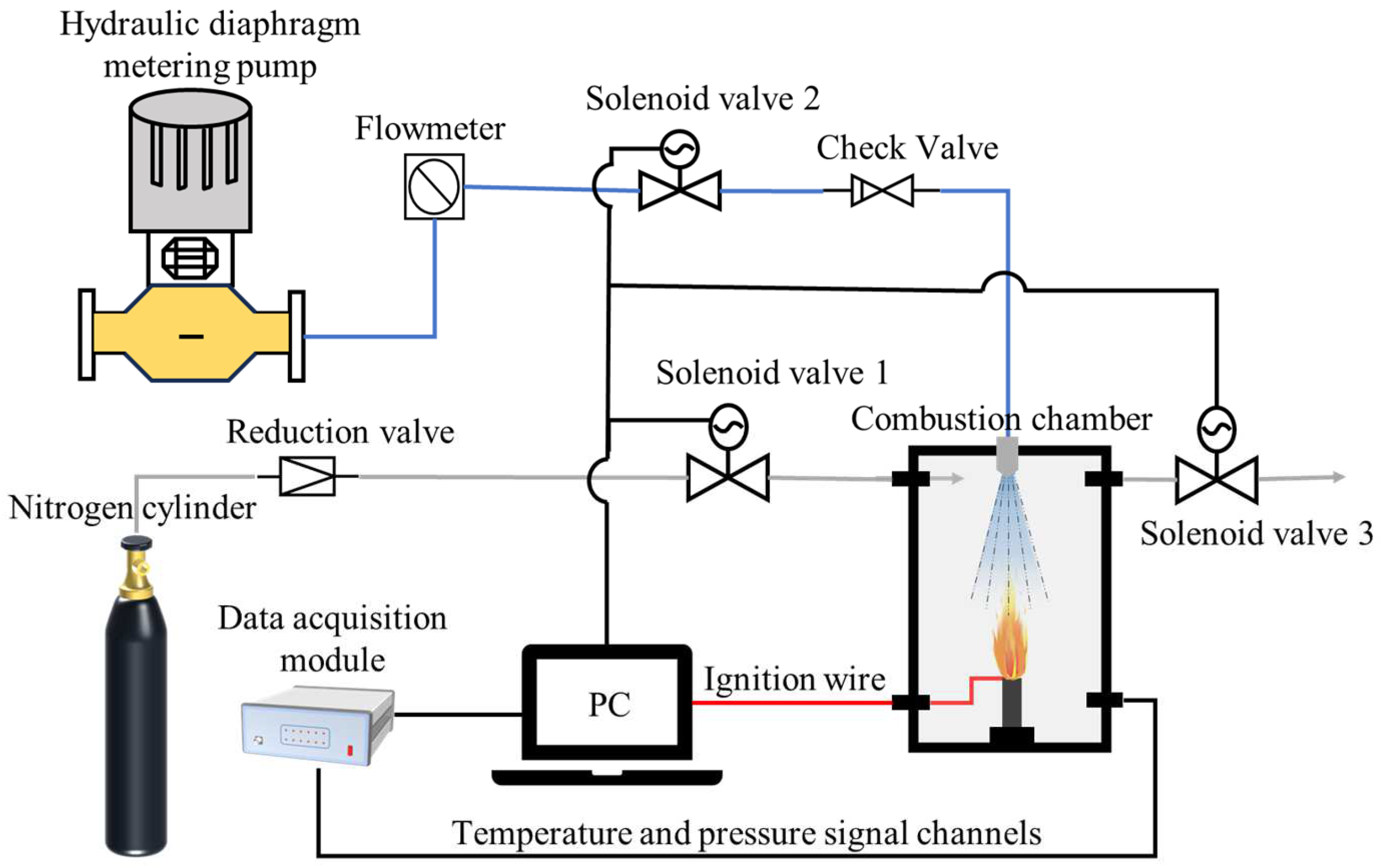
Figure 2 illustrates the diagram of the Mg-based hydroreactive fuels combustion experiment system, consisting of a windowed combustion chamber made of stainless steel (inner radius × height × wall thickness: 40 mm × 100 mm × 10 mm), nitrogen and water inlet pipelines, control system, and measuring instrumentations. The data acquisition system uses DEWESoft Sirius Series acquisition modules and associated data acquisition software to export raw experimental data into various formats for subsequent processing, and the exported data files also carry time information related to the data. The nitrogen inlet pipeline was used to pressurize the combustion chamber, creating the high-pressure environment required for the sample’s combustion. The combustion chamber was fitted with nozzles connected to the external water inlet pipelines to create the water injection required for the combustion of the sample. In order to exclude the interference by other components on the experimental results, we chose distilled water as the water source to inject into the combustion chamber. The distance of the atomizing nozzle from the initial burning surface of the sample could be freely adjusted; in this study it was 90 mm. The velocity of the injection could be varied by adjusting the total pressure of the water flow through the hydraulic diaphragm metering pump, as represented by:
v = 2 ( P s t P i n ) ρ H 2 O
where v is the water injection velocity. ρ H 2 O is the density of water. P represents pressure, with the subscripts st and in representing the total pressure of the water flow and the pressure inside the combustion chamber, respectively.
The specific operation of the experiment mainly involved the installation of the system in the early stage, the pressurization of the combustion chamber, the ignition and water injection process during the experiment, as well as the data saving and the combustion chamber cleaning at the end of the experiment. The burning time of the sample did not exceed 5 s, which took an average of 30 min for a single experiment under the circumstance of no malfunction. The experiment was carried out at room temperature, i.e., an initial temperature of 300 K. The sample was initially placed within the combustion chamber, and the thermocouple data acquisition wire and ignition wire were connected. After the installation in the combustion chamber was complete, nitrogen was flushed through the interior to remove excess air, and the chamber was then pressurized to the experimental pressure. Once the internal pressure of the combustion chamber had stabilized, ignition was achieved, followed by the injection of the water through the pipelines. At the end of the experiment, a solenoid valve was controlled to remove the high-pressure gas from inside the chamber, and then the interior was cleaned of the sample combustion products so that the next experiment could proceed smoothly. The burning rate of the sample was calculated based on the difference between the response times of thermocouples under the same conditions, with three replicates for each condition. The details of the measuring devices involved in the experimental system are shown in Table 1.

3. Numerical Simulation

3.1. Physical Model

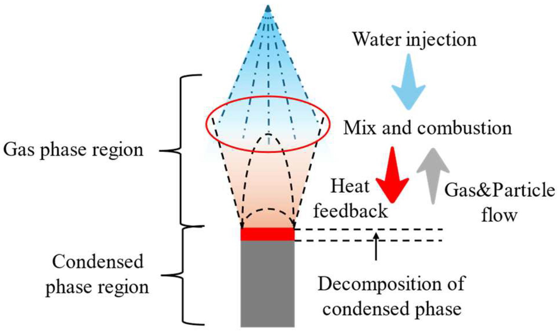
As shown in Figure 3, while combusting the Mg-based hydroreactive fuels, the initial decomposition of the oxidizer and binder occurred, gradually exposing the metal particles embedded in the fuel to the high-temperature airflow resulting from the pyrolysis of the condensed phase [21]. The majority of these particles were carried into the gas phase by the gas flow, forming the fuel-rich gas [9]. On the other hand, the water entered the combustion chamber in droplet form through atomizing nozzles, and the droplets mixed with the fuel-rich gas and combusted intensely, releasing a large amount of heat [13]. Some of the heat released by the non-premixed combustion was transferred back to the condensed phase, sustaining the decomposition of the condensed phase.
To acquire the distribution of the temperature, species, and other parameters within the combustion field, the following suppositions needed to be made:
(1)
The oxidation of the Mg particles occurring at the burning surface was ignored.
(2)
The products in the gas phase were considered ideal gases.
(3)
The reaction of Mg with the water in the gas phase was homogeneous.
(4)
The reaction rate obeyed the Arrhenius Law.

3.2. Mathematical Model

3.2.1. Governing Equations for the Continuous Phase

The N-S equations were used as the governing equations for the continuous phase [29], which can be written as:
ρ t + ( ρ V ) = S m a s s
t ( ρ V ) + ( ρ V V ) = P + τ ¯ ¯ + S m o m e n t u m
t ( ρ E ) + [ V ( ρ E + P ) ] = [ λ T i h i J i + ( τ ¯ ¯ V ) ] + S e n e r g y
t ( ρ Y i ) + ( ρ V Y i ) = J i + R i + S i i = 1 , 2 , 3 , N
where t and V denote the time and velocity, respectively. S is the source term and its subscripts “mass”, “momentum”, “energy” and “i” represent the mass term, momentum term, energy term, and species term. λ is the thermal conductivity. J i , Yi, and Ri denote the diffusion flux, mass fraction, and the net chemical production rate for species i, and N is the total number of species.
The internal energy E and sensible enthalpy h are specified as:
E = 1 ρ i N ρ i h i P + 1 2 V 2
h = i N Y i h i
where hi denotes the sensible enthalpy of species i, which can be given by the expression involving the temperature T [9]:
h i R = a 1 , i + a 2 , i T + a 3 , i T 2 + a 4 , i T 3 + a 5 , i T 4 + a 6 , i T 5
The stress tensor τ ¯ ¯ and diffusion flux J i are defined as:
τ ¯ ¯ = μ ( V + V T ) 2 3 V I
J i = ( ρ D i , m + μ t S c t ) Y i D T , i T T
where D i , m and D T , i denote the mass and thermal diffusion coefficient for species I. S c t is the Schmidt number. I denotes the unit tensor. μt and μ are the turbulence and molecular dynamics viscosity.

3.2.2. Governing Equations for Discrete Particles

As described in Section 3.1, the Mg particles escaping from the burning surface in the combustion field, as well as the incident water droplets, exist as discrete phase particles, and the trajectory of the particles in the combustion field can be obtained by integrating the force act on the particles. Supposing that the particles are only subjected to drag force, the motion equitation of the particles can be expressed as below:
m p d V p d t = m p ( V V p ) τ r
where m p represents the particle mass. V p are velocity vectors for particles. τ r represents the particle relaxation time, which can be defined as:
τ r = ρ p d p 2 18 μ 24 C D R e
where dp and ρp are the diameter and density of the discrete particle, respectively. Re = ρdp| V V p |/μ is the relative Reynolds number. The relationship between the drag coefficient CD and the Reynolds number can be found in Ref. [30].

3.2.3. Combustion Kinetic Model

Referring to the previous work of Ramakrishna et al. [31], the AP decomposition reaction on a burning surface can be written as below:
A P f H C l O 4 + N H 3 + ( 1 f ) 1.5 H 2 O + H C l + 1.25 O 2 + 0.5 N 2
where f is equal to 0.3, and it is supposed that the binder undergoes complete decomposition into C4H6.
A global reaction mechanism, encompassing 12 species, was adopted to illustrate the reaction among the decomposition products originating from the oxidizer and binder in the gas phase with corresponding kinetic parameters referenced in Ref. [32], and the combustion of Mg was represented using the reaction mechanism proposed by Yang et al. [33].
The Finite-Rate/Eddy-Dissipation model was employed to simulate the interaction between the turbulence and reactions, where both the finite-rate reaction rates, and eddy-dissipation rates are calculated; the net reaction rate is taken to be the minimum of these two rates.

3.2.4. Coupling between the Gas and Condensed Phases

Ignoring the exothermic or endothermic reactions that occur in the condensed region, the equation governing the heat transfer along with its associated definite condition can be formulated as follows:
λ c d 2 T d y 2 ρ c r ˙ c p , c d T d y = 0 y = 0 , T = T w y , T = T 0
where cp is the specific heat capacity with the subscript c representing the condensed phase, the subscripts “w” and “0” represent the burning surface and the initial state, respectively, and r ˙ denotes the burning rate.
Based on Equation (13), the temperature distribution in the condensed phase can be written as follows:
T ( y ) = T 0 + ( T w T 0 ) exp ( ρ c c p , c r ˙ y λ c )
According to Section 3.1, the decomposition of the condensed phase provides the reactants for the reactions in the gas phase, and the heat released by the reactions maintains the continued decomposition of the condensed phase. Thus, the interconnection can be described via Equations (15) and (16).
ρ V + ρ c r ˙ = 0
λ g T y = λ c T y w + ρ g V g h g T w ρ c r ˙ h c T w
The energy conservation equation can be simplified by bringing Equation (14), Equation (15), and the enthalpy formula into Equation (16), and the simplified energy conservation equation can be expressed as below:
λ g T y = ρ c r ˙ h g T s h c T 0

3.2.5. Turbulent Governing Equation

The RNG (Re-Normalization Group) k-ε model was adopted for the turbulence simulation in the gas phase, and the transport equations for the turbulent kinetic energy k and turbulent dissipation rate ε can be found in Ref. [34].

3.2.6. Computational Domain and Boundary Conditions

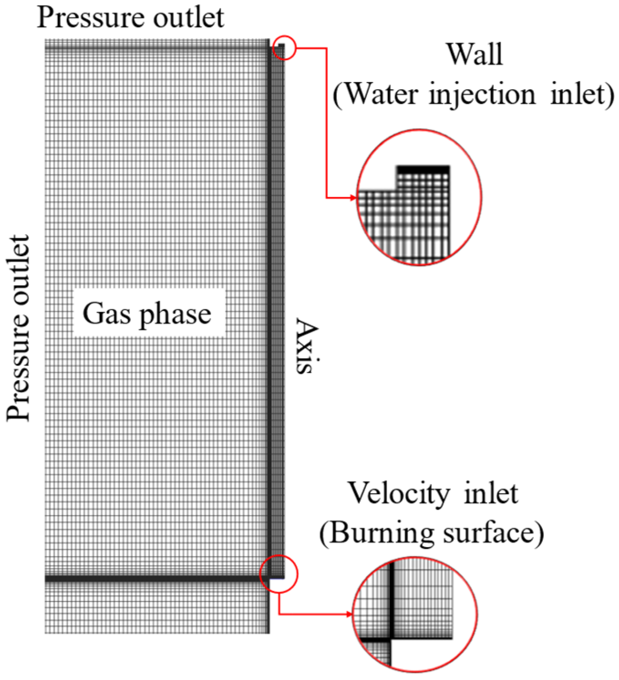
The computational domain and boundary conditions are depicted in Figure 4. To reduce the computational load, half of the combustion field was chosen as the computational domain, given the symmetrical property. Local mesh refinement was implemented to improve the computational precision. The boundary conditions for the other unmentioned boundaries in Figure 4 are a wall. At the outset, the temperature within the combustion field was set to 300 K, assuming that only N2 occupies the computational domain.

4. Results and Discussion

4.1. Model Verification and Validation

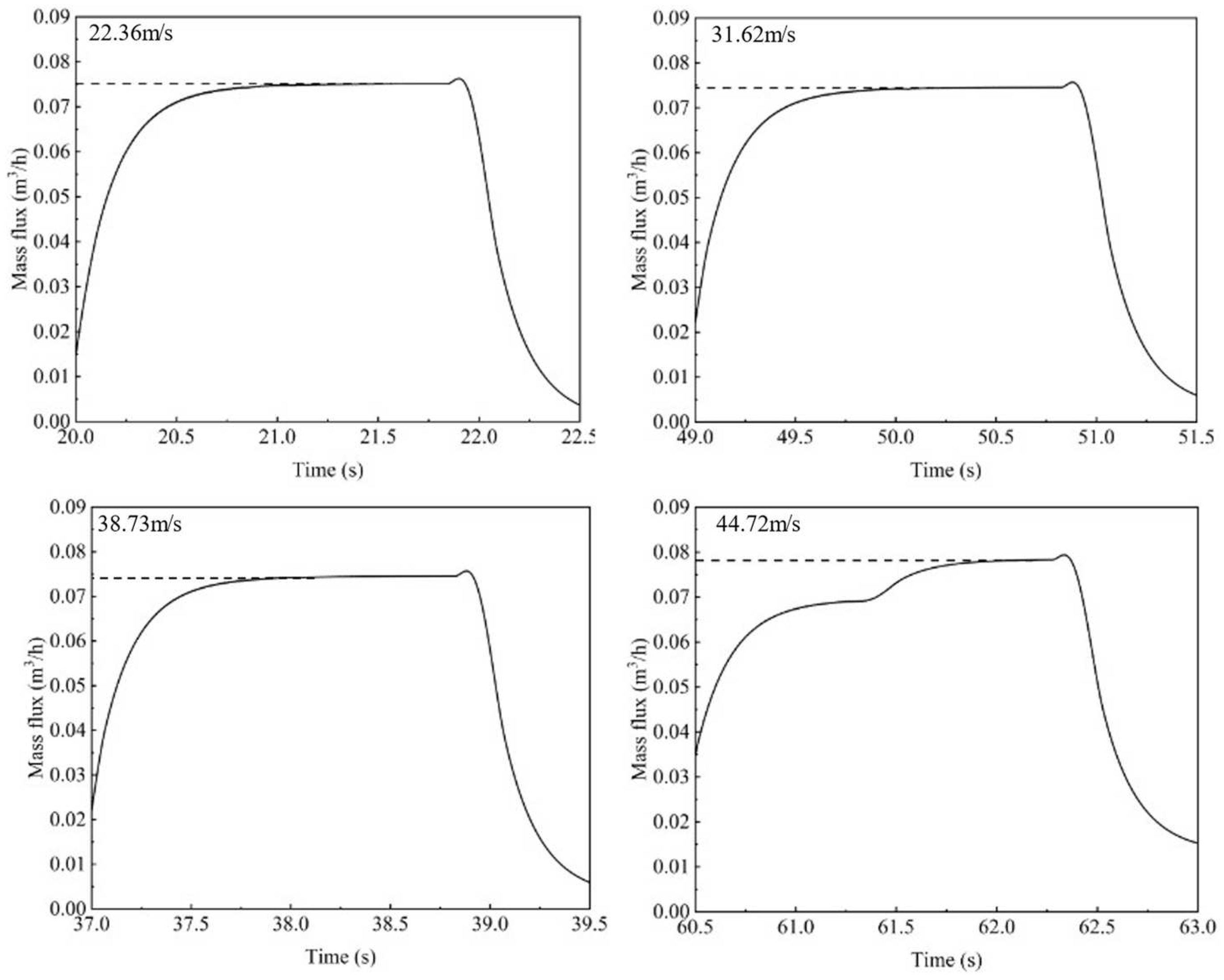
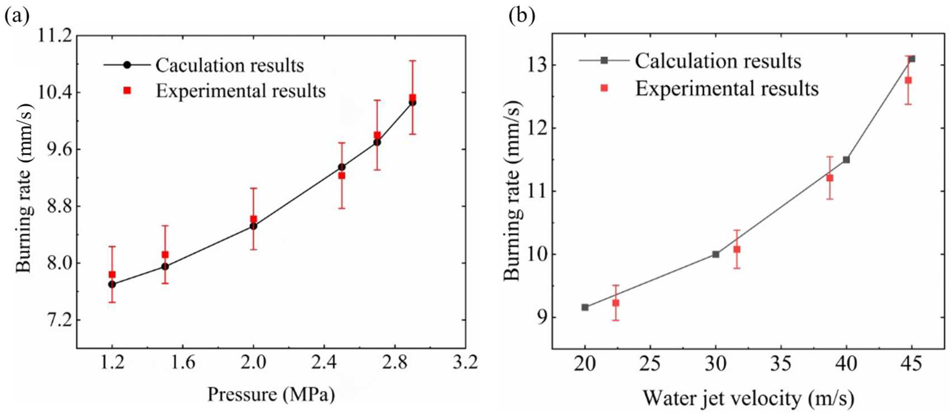
Based on the experimental setup introduced in Section 2.2, the combustion experiments of Mg-based hydroreactive fuels were carried out. Firstly, the other experimental conditions were kept unchanged, and the pressure inside the combustion chamber was adjusted to explore the effect of pressure on the burning rate. Then, the pressure inside the combustion chamber was maintained at 2.5 MPa, and the velocity of the water injection was adjusted to observe the change of the burning rate. Figure 5 shows the variation in the mass flux of water in the inlet pipeline recorded by the flowmeter with time, and the inlet mass flux is basically stable around 0.075 m3/h. A high-speed camera was used to photograph the atomized droplets, and the selected shots are shown in Figure 6a. The Sobel edge and connected domain detection were performed on the resulting large number of images to obtain the percentage of droplets in different size ranges. As shown in Figure 6b, the particle size distribution of the droplets under different injection velocities was mainly concentrated in the vicinity of 100 μm, so it can be approximated that the initial particle size of the droplets was the same. In order to simplify the study, in the simulation of different injection velocities, the initial particle size of the droplets was uniformly selected as 100 μm. Each of the conditions was repeated three times, and the burning rate was taken as the average of three measurements, as shown in Table 2 and Table 3.
The combustion process under different pressures and water injection velocities was simulated by using the established numerical model. Figure 7 illustrates the difference between the burning rates obtained from the experiments and numerical calculations, and the average absolute percentage error (MAPE) for all the cases was less than 5%, indicating the accuracy of the numerical model.

4.2. Flame Structure and Temperature

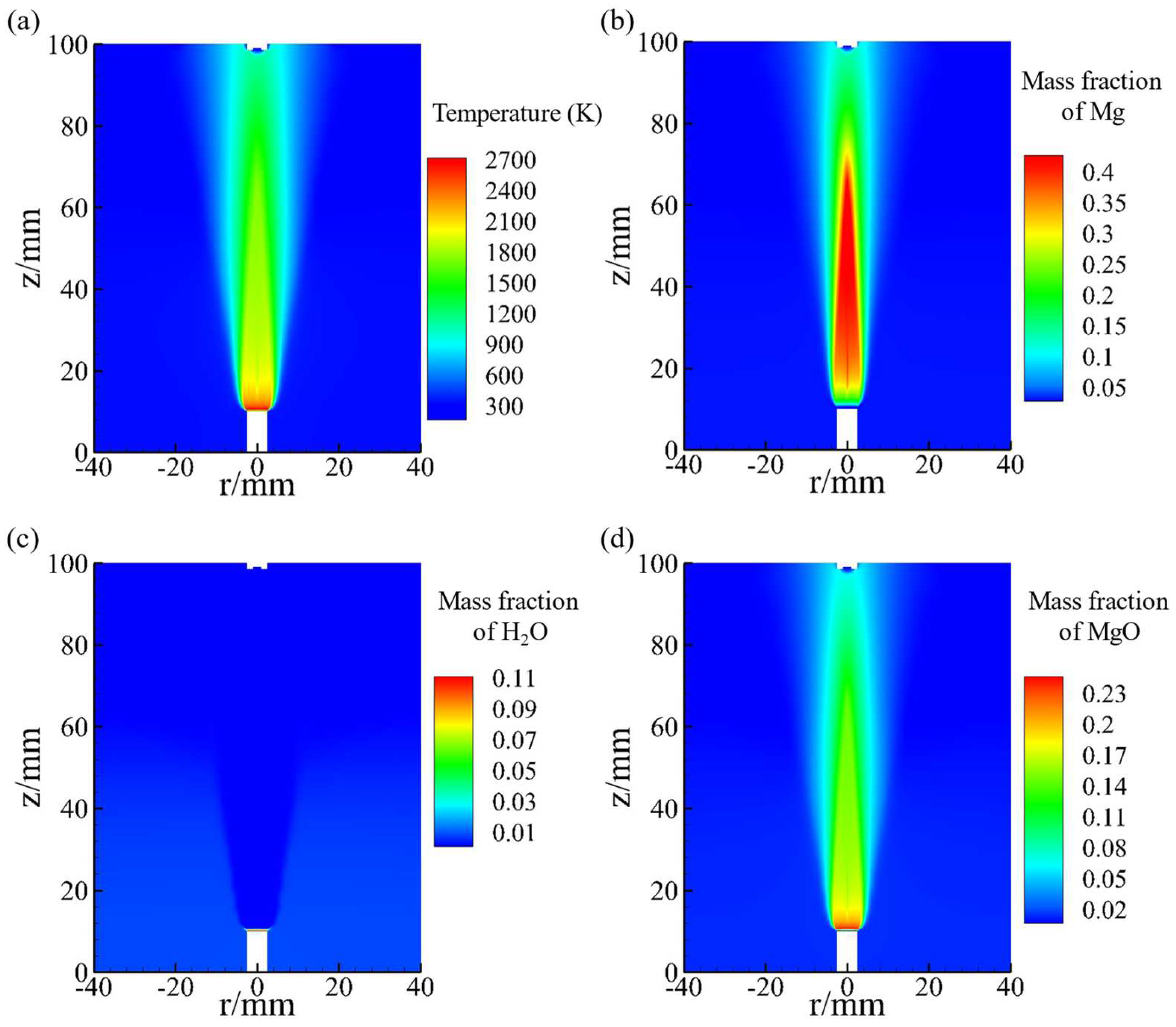
The temperature distribution within the combustion field is depicted in Figure 8a. In the absence of water injection, the flame structure of the Mg-based hydroreactive fuels showed a typal jet property, with substance diffusion predominantly occurring along the axial direction of the sample, while radial diffusion was comparatively subdued, and the highest temperature region was close to the burning surface. Combining the mass fraction contours of Mg, H2O, and MgO shown in Figure 8b–d, it is evident that the distribution of MgO highly coincided with the high-temperature region, while the content of Mg and H2O was extremely low in this area. One explanation for this phenomenon is that during the self-sustaining combustion of Mg-based hydroreactive fuels, the temperature close to the burning surface exceeds the boiling point of magnesium. As the Mg particles separate, they evaporate, releasing a small amount of magnesium vapor, which then reacts with a limited amount of H2O from the thermal decomposition of the oxidizer and binder. Consequently, a localized high-temperature region forms near the burning surface, but it is not significant due to the low content of Mg and H2O vapor. As the Mg particles gradually move away, the water vapor concentration around the Mg particles becomes relatively dilute, resulting in minimal consumption of the Mg vapor from the particle evaporation. Consequently, the Mg vapor content is quite high in the region away from the burning surface, the MgO concentration remains relatively low, and water vapor is virtually absent.
The flame structure of the Mg-based hydroreactive fuels after the addition of the water injection, shown in Figure 9a, exhibited a significant discrepancy compared to Figure 8a. Firstly, the radial diffusion of the flame increased. More importantly, in addition to the original high-temperature region, a new high-temperature region appeared, with temperatures significantly higher than those in the other areas of the combustion field. Figure 9b–d illustrate the spatial distribution of Mg, H2O, and MgO under the water injection velocity of 20 m/s. It is evident that the new high-temperature region in the gas phase significantly overlapped with the distribution of MgO, which indicates that the Mg particles in the gas phase have undergone secondary combustion, namely the non-premixed combustion between Mg and H2O.
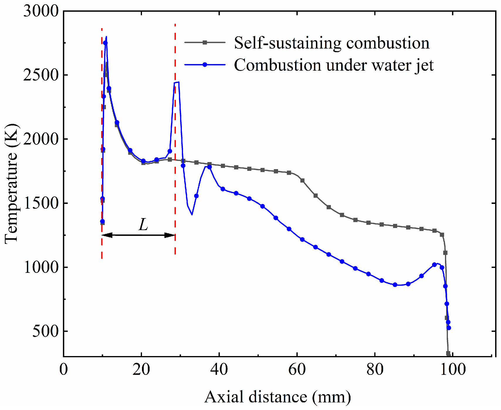
Figure 10 shows the temperature profiles along the sample centerline before and after the injection of a 20 m/s water jet. In the vicinity of the burning surface, the axial temperature profiles were very similar in both conditions, but the temperature maxima was slightly increased via the addition of water injection. As the axial distance increased, the temperature decreased due to the diminishing intensity of the magnesium vapor combustion. With the appearance of a new non-premixed combustion region following the addition of water injection, the axial temperature profile soon exhibited a second peak, which was the flame front of the non-premixed combustion. Define the distance between the second temperature peak and burning surface as the characteristic distance (L) of the non-premixed combustion region. After the flame front, the temperature declined sharply, even lower than that before adding water injection, the reason being that here, the water droplets evaporated in large quantities, absorbing heat, resulting in the emergence of a local low-temperature zone, which also coincided with the distribution H2O as shown in Figure 9c.
In summary, the access of water injection to the flame structure of Mg-based hydrogen-reactive fuels is manifested in two ways: it increases the radial diffusion of the flame and allows the emergence of another high-temperature region in the gas phase caused by the non-premixed combustion of the excess Mg powder and the water droplets after atomization.

4.3. Effect of the Water Jet Velocity

The velocity of the water injection influences the mixing of Mg/H2O during the combustion process. When the inlet water velocity is low, the droplets have a low axial momentum and are diverted by the airflow before reaching the burning surface. Water droplets move axially with the gas and evaporate continuously, resulting in a low penetration of the atomized droplets and insufficient mixing with the fuel-rich gas. As the water injection velocity increases, the penetration of water droplets into the fuel-rich gas is gradually enhanced, reducing the characteristic distance of the non-premixed combustion region, and the effect on the burning surface temperature becomes more pronounced. Therefore, it is necessary to investigate the effect of different water injection velocities on the burning rate of Mg-based hydroreactive fuels.
According to the experimental results presented in Section 4.1, the burning rate of samples increased with a rising water injection velocity. The contour of the temperature in the combustion field under 2.5 MPa and different water injection velocities are shown in Figure 11a; with the increase in water injection velocity, the non-premixed combustion was gradually closer to the burning surface, as shown in Figure 11b. When the water injection velocity was 20 m/s, the characteristic distance of the non-premixed combustion was 19.58 mm, and this value reduced to 10.3 mm when the jet velocity rose to 45 m/s. The burning surface heat flux and temperature are depicted in Figure 11c. Combining the aforementioned information, it can be concluded that the non-premixed combustion region gradually approaches the burning surface as the water injection velocity increases. Therefore, the heat flux on the burning surface rises, leading to an increase in the temperature. This in turn accelerates the decomposition of the oxidizer and binder, which ultimately increases the burning rate. In addition, as shown in Figure 11a, with the increase in water injection velocity, the flame diffusion phenomenon in the radial direction was further strengthened, which can be attributed to the increase in the mixing strength of the water injection and the fuel-rich gas.

4.4. Effect of Water Droplet Particles

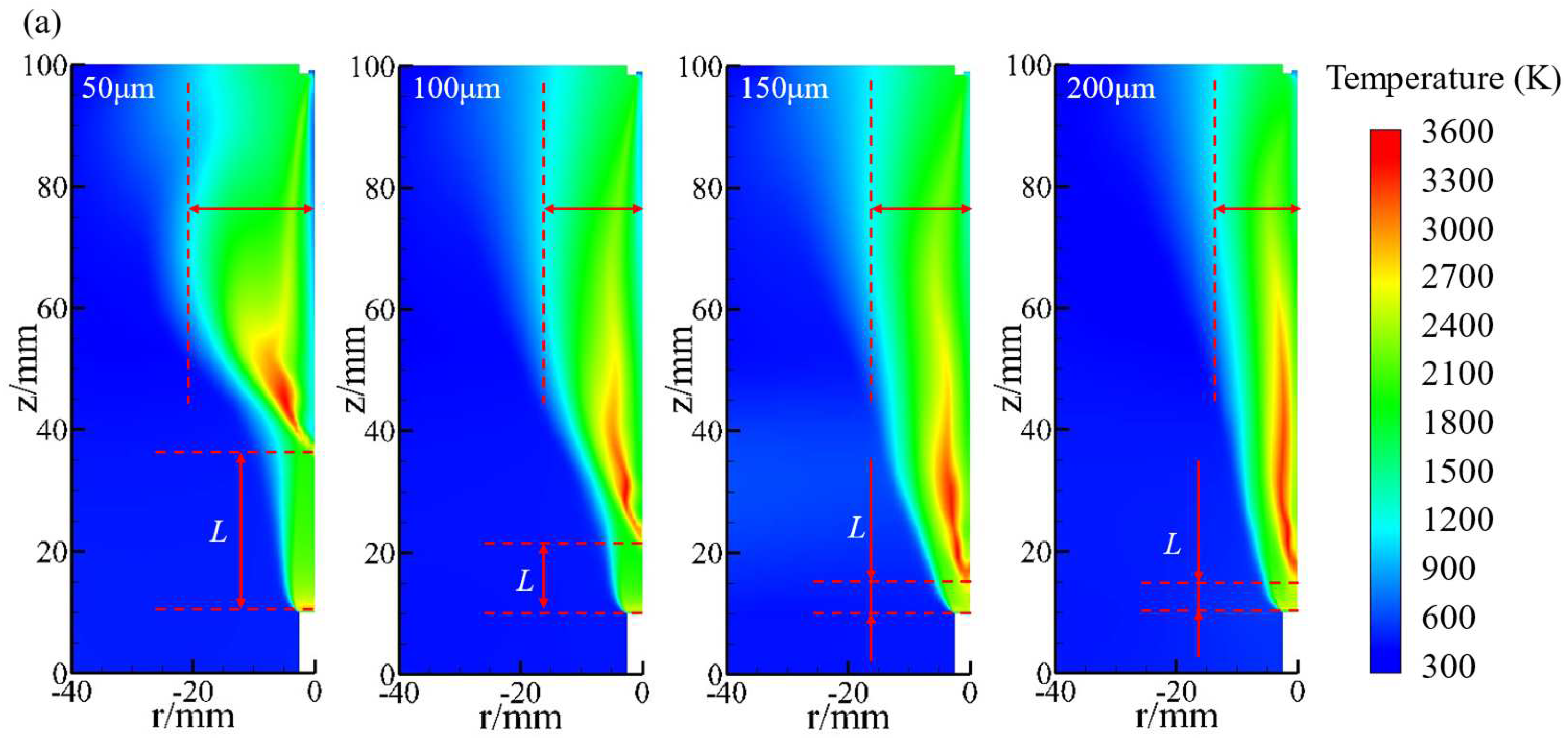
As mentioned earlier, the initial momentum of the droplets directly affects the degree of mixing of the fuel-rich gas with the water injection, and in addition to the velocity, the momentum of the droplets is also affected by their mass (particle diameter). When the initial droplet size is small, it quickly vaporizes upon entering the combustion field, resulting in a lower degree of mixing with the fuel-rich gas. As the initial droplet size increases, the residence time of the droplets in the combustion field lengthens, gradually improving the degree of mixing with the Mg particles, and the non-premixed combustion region also moves towards the burning surface. However, when the droplet size is too large, it cannot fully evaporate, leading to incomplete reactions of Mg, thereby reducing the energy release efficiency of the fuel. Therefore, it is necessary to study the impact of droplet diameter on the combustion process of Mg-based hydroreactive fuels.
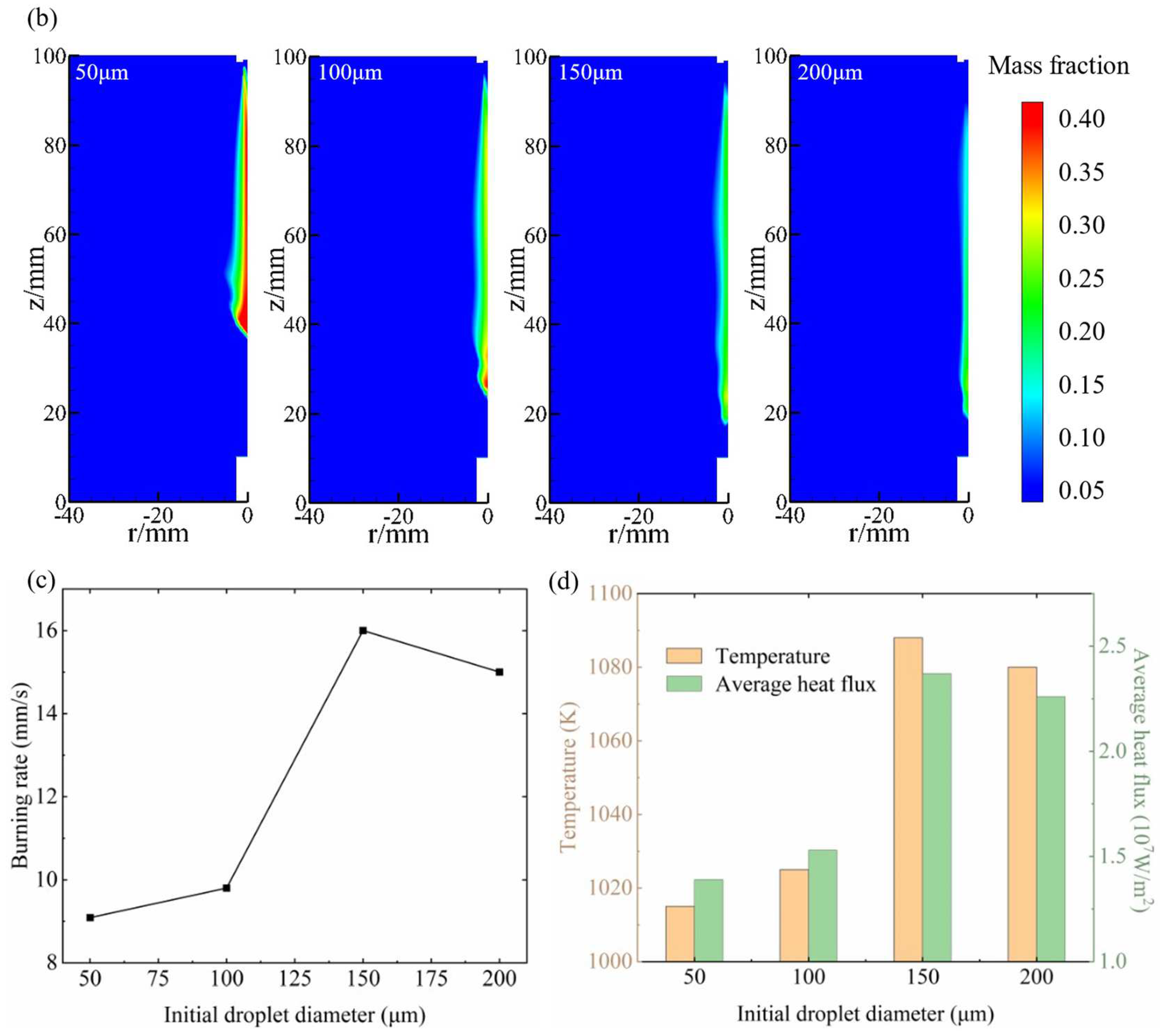
With the pressure and water injection velocity maintained at 2.5 MPa and 20 m/s, respectively, the initial diameter of the water droplet was varied in the DPM model to simulate Mg-based hydroreactive fuels’ combustion. Figure 12a shows the temperature distribution in the combustion field under the initial droplet diameter of 50 μm, 100 μm, 150 μm, and 200 μm, respectively. It can be seen that, with the increasing droplet diameter, the non-premixed combustion region in the combustion field was gradually closer to the burning surface. However, when the droplet size was more than 150 μm, the moving trend was not obvious, and additionally, the radial diffusion of the flame was obviously weakened with the increasing droplet diameter. The distribution of H2O in the combustion field for different droplet diameters is shown in Figure 12b; with increasing droplet size, the maximum value of the mass fraction of the water vapor in the gas phase region showed a gradually decreasing trend. Due to the increasing droplet size, the evaporation of the water vapor in the combustion field was reduced, weakening the impact on the fuel-rich gas flow. This also explains the phenomenon of the weakened radial diffusion of the flame structure.
Figure 12c illustrates how the fuel burning rate varied with the droplet diameter. As the droplet size increased, the burning rate exhibited a trend of initially increasing and then decreasing. This can be explained by the burning surface temperature and heat flux shown in Figure 12d; similar to the injection velocity, an increase in the initial particle diameter of the droplet also enhanced the penetration of the fuel-rich gas, so the doping non-premixed combustion was gradually closer to the burning surface, as shown in Figure 12a. However, if the droplet diameter is too large it will lead to incomplete evaporation, thus reducing the reaction intensity of the Mg/H2O non-premixed combustion, leading to the burning surface of the heat flux having a downward trend, which in turn reduces the burning rate.

5. Conclusions

In this paper, a combination of experimental investigation and numerical simulation was employed to examine the impact of the water injection parameters on the burning rate of the study object. A combustion experimental system which enables the performance of Mg-based hydroreactive fuels combustion experiments under different water injection parameters was developed. In addition, a combustion–flow coupling solution model was developed, involving the reaction mechanism within the fuel-rich gas as well as between excessive Mg and the water vapor from the evaporation of droplets. The MAPE of the calculation results was less than 5% for all the cases, proving the validity of the present model. The main findings of this paper are as follows:
(1)
Compared to the self-sustained combustion, the addition of water injection formed a new Mg/H2O non-premixed combustion region in the gas phase.
(2)
Additionally, the initial momentum of the droplet affects the mixing degree of the water injection and the fuel-rich gas, which is related to the initial velocity and the initial droplet size (mass). The higher the velocity of the water injection, the stronger the penetration ability of the water droplets into the fuel-rich gas, bringing the Mg/H2O non-premixed combustion region towards the burning surface, which increased the heat flux, resulting in a positive correlation between the fuel burning rate and injection velocity.
(3)
To a certain extent, the correlation between the droplet diameter and burning rate also followed this pattern; however, an excessive droplet diameter may cause incomplete evaporation, leading to a minor reduction in the burning rate.
These discoveries deepen the understanding of the combustion behavior of Mg-based hydroreactive fuels, offering a theoretical instruction for the precise prediction of the burning rate and optimal selection of the operating parameters for water ramjet engines. In the next stage of our study, we plan to modify the existing combustion chamber to exclude the interference from the smoke generated by the combustion of the samples, introduce optical diagnostics in the experiments to capture the real process of energy release from Mg-based hydroreactive fuels, and conduct further studies on their combustion characteristics.

Author Contributions

Conceptualization, S.S. and S.Y.; methodology, W.A.; software, H.Q.; validation, S.S., W.A. and P.L.; formal analysis, S.S.; investigation, S.Y.; resources, H.Q.; data curation, W.A. and P.L.; writing—original draft preparation, S.S. and S.Y.; writing—review and editing, W.A., P.L., S.S. and S.Y.; funding acquisition, P.L. All authors have read and agreed to the published version of the manuscript.

Funding

This work is supported by the National Natural Science Foundation of China (No. 22375164) and Key Research and Development Program of Shaanxi (No. 2023KJXX-005).

Data Availability Statement

The data presented in this study are available on request from the corresponding author. The data are not publicly available due to due to restrictions privacy.

Conflicts of Interest

Author Hong Qiao is employed by China State Shipbuilding Corporation Limited. The remaining authors declare that the research was conducted in the absence of any commercial or financial relationships that could be construed as a potential conflict of interest.

References

  1. Boryaev, A.A. Calculation and experimental estimation of the efficiency of using lithium, sodium, magnesium, and aluminum as fuels in hydro-reactive propellants. Therm. Sci. Eng. Prog. 2021, 23, 100881. [Google Scholar] [CrossRef]
  2. Zhang, J.; Xia, Z.; Huang, L.; Ma, L. Power cycle analysis of two-phase underwater ramjet. Appl. Ocean Res. 2018, 71, 69–76. [Google Scholar] [CrossRef]
  3. Shi, H.; Ren, J.; Tang, W.; Li, J.; Yang, R. Effect of fast-burning compound ACP and catalyst on the combustion performance of Al/Mg-based fuel-rich HTPB propellants. FirePhysChem 2022, 2, 28–35. [Google Scholar] [CrossRef]
  4. Ao, W.; Zhang, Y.; Liu, L.; Huo, C.; Liu, P.; Li, L.K.B. Ignition and combustion experiments on Mg/AP composite fuels in different reaction environments. Combust. Flame 2023, 247, 112505. [Google Scholar] [CrossRef]
  5. Ghassemi, H.; Farshi Fasih, H. Investigation of interior ballistics and performance analysis of hydro-reactive motors. Aerosp. Sci. Technol. 2015, 41, 99–105. [Google Scholar] [CrossRef]
  6. Ghassemi, H.; Farshi Fasih, H. Propulsive characteristics of metal fuel-rich pyrotechnics in hydro-reactive motors. Aerosp. Sci. Technol. 2013, 28, 1–8. [Google Scholar] [CrossRef]
  7. Zou, M.; Yang, R.; Guo, X.; Huang, H.; He, J.; Zhang, P. The preparation of Mg-based hydro-reactive materials and their reactive properties in seawater. Int. J. Hydrogen Energy 2011, 36, 6478–6483. [Google Scholar] [CrossRef]
  8. Liu, J.; Wang, Y.; Li, X.; Cong, J. Using the Impulse Method to Determine High-Pressure Dynamic Burning Rate of Solid Propellants. Aerospace 2023, 10, 818. [Google Scholar] [CrossRef]
  9. Zhang, K.; Han, Y.; Ren, D.; Zhu, C. Experimental and numerical investigations of the effect of pressure on combustion characteristics of Mg-based solid fuels. Fuel 2021, 305, 121529. [Google Scholar] [CrossRef]
  10. Wang, Z.; Yu, K.; Liu, Y. A Discontinuous Galerkin–Finite Element Method for the Nonlinear Unsteady Burning Rate Responses of Solid Propellants. Aerospace 2024, 11, 97. [Google Scholar] [CrossRef]
  11. Ao, W.; Wen, Z.; Liu, L.; Liu, P.; Gan, Y.; Wang, L.; Li, L.K.B. Controlling the combustion and agglomeration characteristics of a solid composite propellant via a DC electric field. Aerosp. Sci. Technol. 2022, 128, 107766. [Google Scholar] [CrossRef]
  12. Hu, J.; Han, C.; Xia, Z.; Huang, L.; Huang, X. Experimental Investigation on Combustion of High-Metal Magnesium-Based Hydroreactive Fuels. J. Propuls. Power 2013, 29, 692–698. [Google Scholar] [CrossRef]
  13. Huang, H.; Zou, M.; Guo, X.; Yang, R.; Li, Y. Analysis of the aluminum reaction efficiency in a hydro-reactive fuel propellant used for a water ramjet. Combust. Explos. Shock Waves 2013, 49, 541–547. [Google Scholar] [CrossRef]
  14. Huang, H.; Zou, M.; Guo, X.; Yang, R.; Zhang, P. Analysis of the Solid Combustion Products of a Mg-Based Fuel-Rich Propellant used for Water Ramjet Engines. Propellants Explos. Pyrotech. 2012, 37, 407–412. [Google Scholar] [CrossRef]
  15. Huang, H.; Zou, M.; Guo, X.; Yang, R.; Li, Y.; Jiang, E.; Li, Z. Study of Different Al/Mg Powders in Hydroreactive Fuel Propellant Used for Water Ramjet. J. Energetic Mater. 2014, 32, S83–S93. [Google Scholar] [CrossRef]
  16. Huang, L.; Zhang, W.; Xia, Z.; Hu, J.X. Experimental Study on Ignition Process of a Magnesium-Based Water Ramjet Engine. J. Propuls. Power 2014, 30, 857–862. [Google Scholar] [CrossRef]
  17. Huang, L.; Xia, Z.; Hu, J.; Zhu, Q. Performance study of a water ramjet engine. Sci. China Technol. Sci. 2011, 54, 877–882. [Google Scholar] [CrossRef]
  18. Sun, D.; Li, Y.; Liu, P.; Chen, B.; Fan, W. Numerical Investigation on the Effect of Ammonium Perchlorate Content and Position on the Combustion Characteristics of an Ammonium Perchlorate/Hydroxyl-Terminated Polybutadiene Propellant. Aerospace 2023, 10, 692. [Google Scholar] [CrossRef]
  19. Yue, S.; Liu, L.; Liu, H.; Jiang, Y.; Liu, P.; Pang, A.; Zhang, G.; Ao, W. Agglomerate Size Evolution in Solid Propellant Combustion under High Pressure. Aerospace 2023, 10, 515. [Google Scholar] [CrossRef]
  20. Martinez-Sanchis, D.; Sternin, A.; Haidn, O.; Tajmar, M. Combustion Regimes in Turbulent Non-Premixed Flames for Space Propulsion. Aerospace 2023, 10, 671. [Google Scholar] [CrossRef]
  21. Hu, J.; Han, C.; Xia, Z.; Huang, L.; Huang, X. Statistical model for combustion of high-metal magnesium-based hydro-reactive fuel. Chin. Phys. B 2012, 21, 124501. [Google Scholar] [CrossRef]
  22. Beckstead, M.W.; Derr, R.L.; Price, C.F. A model of composite solid-propellant combustion based on multiple flames. AIAA J. 1970, 8, 2200–2207. [Google Scholar] [CrossRef]
  23. Gross, M.L.; Hedman, T.D.; Son, S.F.; Jackson, T.L.; Beckstead, M.W. Coupling micro and meso-scale combustion models of AP/HTPB propellants. Combust. Flame 2013, 160, 982–992. [Google Scholar] [CrossRef]
  24. Gross, M.L.; Beckstead, M.W. Diffusion flame calculations for composite propellants predicting particle-size effects. Combust. Flame 2010, 157, 864–873. [Google Scholar] [CrossRef]
  25. Choi, H.; Yoh, J.J. A grain-scale modeling on the surface burning and agglomeration of the metalized solid propellants. Combust. Flame 2024, 261, 113284. [Google Scholar] [CrossRef]
  26. Zhu, M.; Chen, X.; Zhou, C.; Xu, J.; Musa, O.; Xiang, H. Experimental and numerical investigations on the decomposition and combustion characteristics of composite propellant with Mg/Al particles additives. Appl. Therm. Eng. 2017, 111, 863–875. [Google Scholar] [CrossRef]
  27. Zhang, K.; Han, Y.; Ren, D.; Zhu, C. Experimental and numerical analyses of the combustion characteristics of Mg/PTFE/Viton fuel-rich pyrolants in the atmospheric environment. Numer. Heat Transf. Part A Appl. 2020, 78, 180–198. [Google Scholar] [CrossRef]
  28. Zhang, K.; Han, Y.; Ren, D.; Zhu, C. Experimental and numerical investigations on the condensed combustion products of Mg-based solid fuels. Fuel 2022, 329, 125423. [Google Scholar] [CrossRef]
  29. Zou, X.; Wang, N.; Wang, C.; Wang, J.; Tang, Y.; Shi, B. Investigation on the microscale combustion characteristics of AP/HTPB propellant under wide pressure range. Fuel 2021, 306, 121652. [Google Scholar] [CrossRef]
  30. Morsi, S.A.; Alexander, A.J. An investigation of particle trajectories in two-phase flow systems. J. Fluid Mech. 1972, 55, 193–208. [Google Scholar] [CrossRef]
  31. Ramakrishna, P.A.; Paul, P.J.; Mukunda, H.S. Sandwich propellant combustion: Modeling and experimental comparison. Proc. Combust. Inst. 2002, 29, 2963–2973. [Google Scholar] [CrossRef]
  32. Liu, L.; Zhang, G.; Wen, Z.; Li, S.; Liu, P.; He, G.; Ao, W. Numerical investigation and experimental validation of aluminized propellant combustion under high pressures: Critical effects of heat feedback. Aerosp. Sci. Technol. 2024, 147, 109032. [Google Scholar] [CrossRef]
  33. Yang, W.; Han, Z.; Zhou, J.; Liu, J.; Cen, K. Theoretical study on the reaction of magnesium with water in the gas-phase. Int. J. Hydrogen Energy 2011, 36, 10608–10613. [Google Scholar] [CrossRef]
  34. Analytis, G.T. Implementation of the renormalization group (RNG) k–ε turbulence model in GOTHIC/6.lb: Solution methods and assessment. Ann. Nucl. Energy 2003, 30, 349–387. [Google Scholar] [CrossRef]
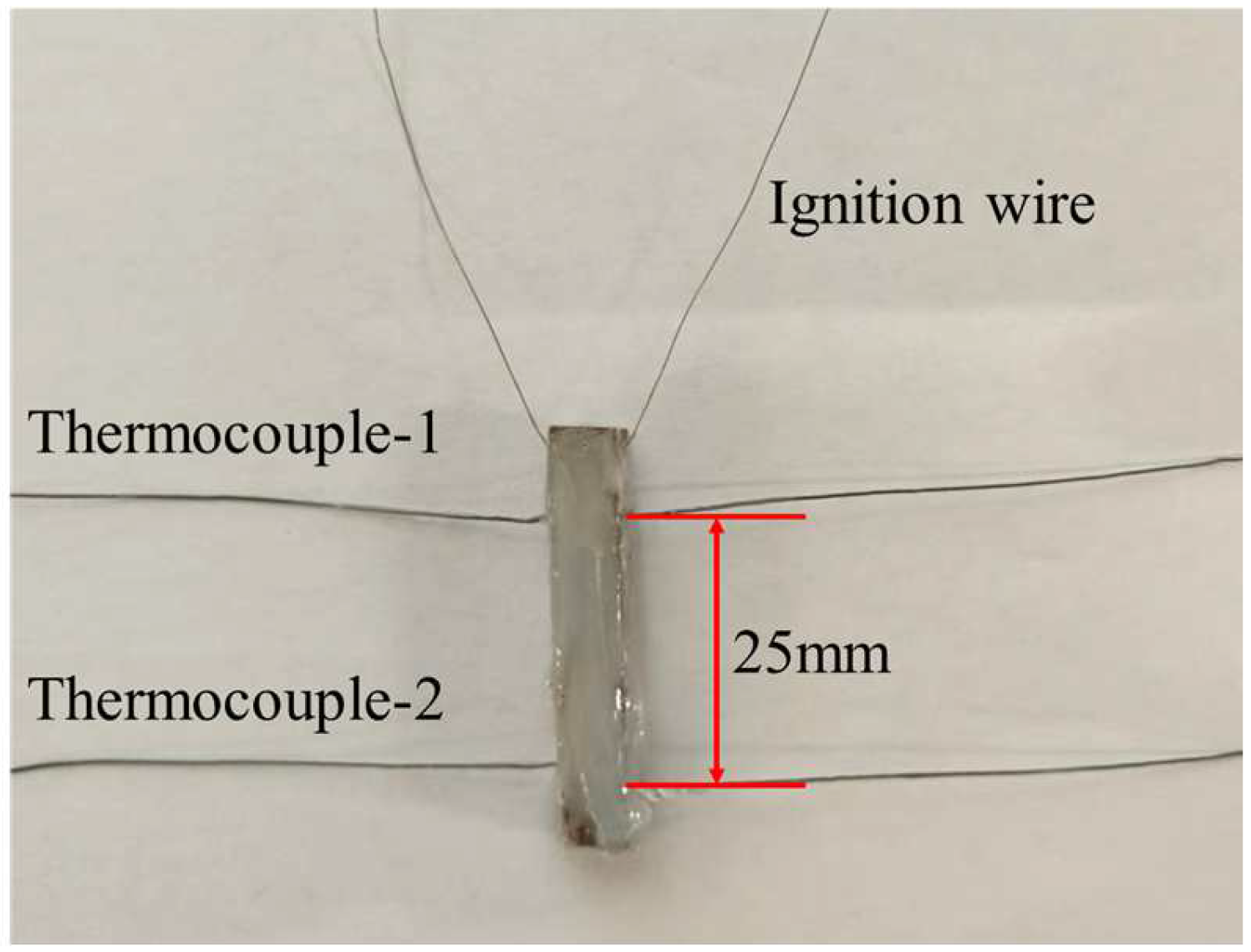
Figure 1. Prepared sample with inserted thermocouples and ignition wire.
Aerospace 11 00542 g001
Figure 2. Schematic diagram of experimental facility.
Aerospace 11 00542 g002
Figure 3. The combustion diagram of Mg-based hydroreactive fuels.
Aerospace 11 00542 g003
Figure 4. Computational domain and boundary conditions.
Aerospace 11 00542 g004
Figure 5. Mass fluxes in the inlet pipework as recorded by the flowmeter.
Aerospace 11 00542 g005
Figure 6. (a) Selected shots captured by the high-speed camera and (b) distribution of droplet sizes at different injection velocities.
Aerospace 11 00542 g006
Figure 7. Comparison of burning rates of Mg-based hydroreactive fuels for different (a) pressures and (b) water injection velocities.
Aerospace 11 00542 g007
Figure 8. The temperature (a) and mass fraction contour of the major species ((b) Mg, (c) H2O, (d) MgO) of Mg-based hydroreactive fuels self-sustained combustion at 2.5 MPa.
Aerospace 11 00542 g008
Figure 9. The temperature (a) and mass fraction contour of the major species ((b) Mg, (c) H2O, (d) MgO) in the combustion field of Mg-based hydrogen-reactive fuels after water injection at 20 m/s and 2.5 MPa.
Aerospace 11 00542 g009
Figure 10. Temperature profile along the sample centerline.
Aerospace 11 00542 g010
Figure 11. The (a) temperature contour, (b) characteristic distance of the non-premixed combustion region, and (c) burning surface temperature and heat flux under different water jet velocities.
Aerospace 11 00542 g011
Figure 12. The (a) temperature contour, (b) mass fraction contour of H2O, (c) burning rate, and (d) burning surface temperature and heat flux under different water droplet diameters.
Aerospace 11 00542 g012aAerospace 11 00542 g012b
Table 1. Detailed information on measuring devices.
NameBrandingModelMeasurement RangeAccuracy
Pressure sensorsXing HangPTA-10G21G1020–10 MPa0.25% F.S
FlowmeterXi ChuangLWG-Y-40–0.25 m3/hRepeatability: ≤0.2%
ThermocoupleCheng LinTT-K-3073–1673 K±2.5 K
Data Acquisition ModuleDeweSoftSIRIUS® XHS--
Data Acquisition SoftwareDeweSoftDeweSoftX-64bit--
Table 2. Average burning rate under different pressures.
Pressure (MPa)1.21.52.02.52.72.9
Burning rate (mm/s)7.848.128.629.239.8010.33
Table 3. Average burning rate under different water injection velocities.
Water injection velocity (m/s)22.3631.6238.7344.72
Burning rate (mm/s)7.848.128.629.23
Disclaimer/Publisher’s Note: The statements, opinions and data contained in all publications are solely those of the individual author(s) and contributor(s) and not of MDPI and/or the editor(s). MDPI and/or the editor(s) disclaim responsibility for any injury to people or property resulting from any ideas, methods, instructions or products referred to in the content.