Article

Improved Multi-Body Dynamic Simulation of Landing Gear Drop Test Incorporating Structural Flexibility and Bearing Contact

1
School of Astronautics, Harbin Institute of Technology, Harbin 150001, China
2
Shanghai Aircraft Design and Research Institute, Shanghai 201210, China
*
Author to whom correspondence should be addressed.
Aerospace 2024, 11(7), 543; https://doi.org/10.3390/aerospace11070543
Submission received: 27 April 2024 / Revised: 6 June 2024 / Accepted: 1 July 2024 / Published: 2 July 2024
(This article belongs to the Special Issue Landing System Design in Aerospace)

Abstract

:
The investigation of multi-body dynamics (MBD) modeling for landing gear drop tests is a hot topic in the realm of landing gear design. The current results were primarily focused on the multi-rigid body simulation or a simple multi-flexible body simulation, with little regard for the correctness of longitudinal loads and their experimental confirmation, particularly wheel–axle loads. Based on a genuine oleo-pneumatic landing gear drop test of a large civil aircraft, enhanced multi-body dynamics simulation research is carried out, considering the structural flexibility and bearing support by adopting flexible multi-bodies modeling and rigid-flex coupling contacts. When compared to the test data, which purposefully measured the longitudinal wheel–axle loads, the simulation results show that the loads, shock absorber compression, and shock absorber inner pressures are all within good agreement. Furthermore, the influence of structural stiffness and bearing contact was investigated by adjusting the model settings to confirm their importance.

1. Introduction

The landing gear is an important component that helps the airframe mitigate the impact and dissipate energy during takeoff, landing, taxiing, and other ground handling conditions [1,2,3]. The landing gear drop test simulates the process of an aircraft landing by dropping the landing gear to a reaction table from a high position in laboratory conditions so as to ensure that the cushioning characteristics, designed parameters, and structural reliability meet the design requirements [4]. As a crucial test verification link in landing gear design, every newly created landing gear must be confirmed by the landing drop test. There are corresponding requirements for it in both civil and military specifications to assure standardization and validity [5].
Simulation of the landing gear drop test can be used to analyze the cushioning characteristics of the landing gear in advance before the official start of the test so as to prepare for the test, reduce the risk of the test, shorten the design cycle, and reduce the cost of the design. Additionally, the analysis situation of the model can be further extended to the real operating scenarios, not limited to the test conditions. Therefore, more specific aircraft landing scenarios can be analyzed to ensure the comprehensiveness of the design work, as well as the aircraft’s safety. Therefore, it has always been the focus in the field of landing gear design [6,7]. Landing gear drop test simulation technology, also known as landing simulation technology, has emerged as a critical tool for designing landing loads for both the landing gear structure and the aircraft fuselage, particularly for large civil aircraft.
But overall, the test and simulation are mutually validating and corrective [8]. Overview of the current research status of tests and simulation: In the last decade, many scholars, such as D. Scott Norwood, Xue CaiJun, Huaitao Wang, Gan Shenyong, Byun-Hyuk Kang, etc., published research results of landing gear drop tests or simulation techniques [9,10,11,12,13]. These experimental studies were usually carried out together with simulation studies, so it can be seen that they are complementary and indispensable.
In the experimental studies, people progressively began to pay attention to the validation of longitudinal qualities in the landing gear drop test, particularly the spin-up and spring-back of the wheel mass, also known as the gear walk phenomena (fore/aft movement) [14,15,16]. It is generated by the coupled effects of the structural flexibility of the landing gear and the wheel rotation after the wheel rubs violently against the ground in the landing impact. Unlike the shimmy phenomenon (torsion), another key landing gear dynamic issue caused by the similar coupling effect, the landing gear drop test is only concerned with the very short period, about 0.5 s, of the first cushion stroke at the beginning of the landing impact, whereas the shimmy test is more concerned with the high-speed taxiing process after that. However, the gear walk phenomenon has long been noted in the design of aircraft and landing gears; due to the nonlinear complexity of the mechanism behind the phenomenon, most of the previous tests were often conducted in simple ways, such as only measuring the tire’s grounding point loads for verification, but the more important wheel–axle point loads were usually not taken into account. Less attention was paid to the accurate dynamics characteristics of the wheel rotation and wheel–axle forward and backward motions. This has also led to the fact that the verification of the longitudinal characteristics was less published in various simulation studies. It is acceptable in some design specifications, if conservative, but not a fine or accurate method.
In simulation and analysis studies, the current, more mature approach is to simplify the landing gear dynamics to a multi-degree-of-freedom system consisting of multiple mass blocks, as well as establish the Newtonian Euler equations of motion and solve them using a computer language [17,18]. The key benefits of this method are clearer and more mature mathematical principles, as well as faster program-solving speeds, while the downsides include a greater level of theoretical study and lower scalability in cooperation with other simulation systems. In addition to the traditional method, the rapidly developing computational multi-body dynamics (MBD) and virtual prototype technology are used to conduct the landing drop test simulation [7]. It is a hot spot of research at present. It offers the advantages of being simple to use, allowing for three-dimensional visualization, and integrating well with other computer-aided engineering (CAE) technologies. MBD software has a powerful interface function, which opens up new opportunities for the development of aircraft-level simulations that are combined with multi-system joint technology.
The two most prominent MBD software applications—the MSC.ADAMS and LMS.motion—have been widely used in the field of aircraft design [19,20], as well as the field of landing gear dynamics simulation. However, there are still some areas that need to be improved. For example, in the field of multi-body stuff simulation, two hot issues —multi-flexible body simulation and friction contact problem [21]—similarly arise in landing gear simulation. They are associated with the gear walk phenomenon produced by structural flexibility and the subsequence problem of bearing contact modeling inside the buffer. They must undoubtedly be taken into account while developing a high-fidelity simulation model.
In 2019, Kadam conducted an ADAMS simulation study of a landing gear in which a multi-rigid body system was used instead of a flexible body, so the system was able to simulate the cushioning characteristics of the axial direction accurately but was unable to account for the gear walk caused by flexibility [22]. This issue was further proved by Huang Mingyang’s study in 2022, which confirmed that taking elastic deformation into account is critical when analyzing longitudinal loads [23]. In 2021, Stachiw conducted research to confirm that the flexibility of the aircraft fuselage construction also has an impact on the landing dynamics characteristics [24]. All of these studies demonstrate that taking into account the structural flexibility in landing gear simulation is a challenge but must be addressed in the future.
Zhang Ming performed a multi-body dynamics simulation of trolley-type landing gear using LMS.motion in 2022, using a multi-flexible body system and analyzing the longitudinal loads, but without experimental verification [25]. The flexible body modeling technique utilized in Zhang Ming’s research was analogous to a beam-coupling processing method [15], which coupled important components, such as the outer cylinder and the piston rod, by the finite beam element. However, there is no indication in the above model whether the bearing contact characteristics were well considered or not, whereas Sanjay Baskaran, Wei Xiaohui, Gan Shengyong, and others demonstrated that the bearing contact has an effect on buffer characteristics, which must also be considered in the study of cushioning characteristics or hysteresis performance [12,26].
Based on the above research findings, it can be concluded that reasonably accounting for the coupling effect of strut flexibility and bearing friction in the modeling of the multi-body dynamic simulation of the landing gear drop test is a problem that is currently under-researched. The solution to this problem will improve the landing gear multi-body dynamics simulation method and yield better simulation results.
To that aim, this research proposes using a specific sort of landing gear real drop test as a modeling item to improve the MBD simulation approach. Firstly, we seek to analyze the internal dynamic phenomena and principles in the drop test procedure to determine the mutual motion and force transmission relationships among the parts. Secondly, based on the analysis of the dynamic characteristics of the landing gear in the vertical direction, longitudinal direction, wheel rotation, and other degrees of freedom, as well as the multiple body dynamics theory and the application method of software ADAMS V2017.2, a modeling method considering the influence of structural flexibility and bearing friction is proposed, so as to establish the simulation model. Finally, the feasibility of this multi-body modeling method is illustrated through the comparison of the simulation results with the experimental test data and also through the setting changes of the model to analyze whether the structural flexibility and bearing friction will have an influence on the simulation accuracy.
The results reveal that the data acquired by this modeling and simulation method is consistent with the experimental results, demonstrating that the flexible body modeling and bearing friction contact modeling methods are viable. Furthermore, a comparative study of the changes in flexibility and bearing friction reveals that the longitudinal load deviation caused by not considering structure flexibility can be completely different, and the wheel–axle loads turn similar to the tire–ground contact forces. The bearing friction influence is smaller but unneglectable. All of this clarifies the importance of flexible bodies and bearing contact in the MBD simulation of the landing gear drop test and serves as a reference for future research.

2. Materials and Methods

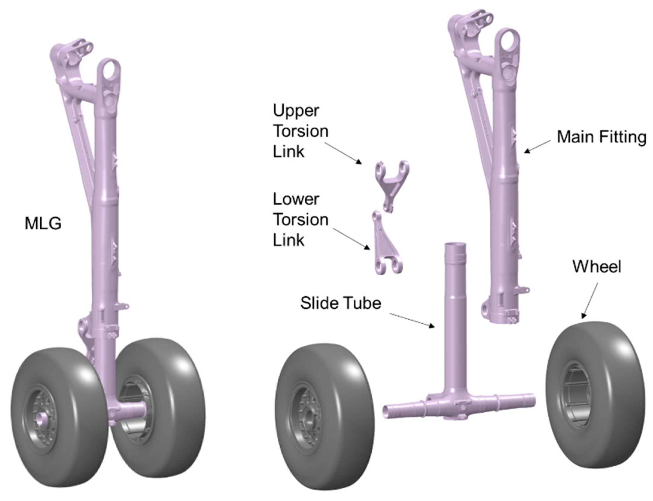
2.1. Structural Parts

Figure 1 displays the structural parts schematic for the main landing gear, which is studied in this paper. It has an outer cylinder (main fitting), a piston (slide tube), two torsion links, and two wheels (with tire) in it. The wheel axle is symmetrically installed with two wheels and incorporated at the bottom of the piston. The piston and outer cylinder combine to form the oleo-pneumatic shock absorber chamber. The shock absorber includes a variable-section metering pin and fixed oil orifices in a conventional single-chamber oleo-pneumatic arrangement. The gas in the chamber is compressed or expanded during the instroke and outstroke movements, producing varying spring forces. As this is occurring, the oil flows through the inside holes at varying speeds and portions, producing varying damping forces. Two factors cooperate throughout the landing impact phase to lessen the impact, decrease the loads, dissipate the energy, and improve comfort.

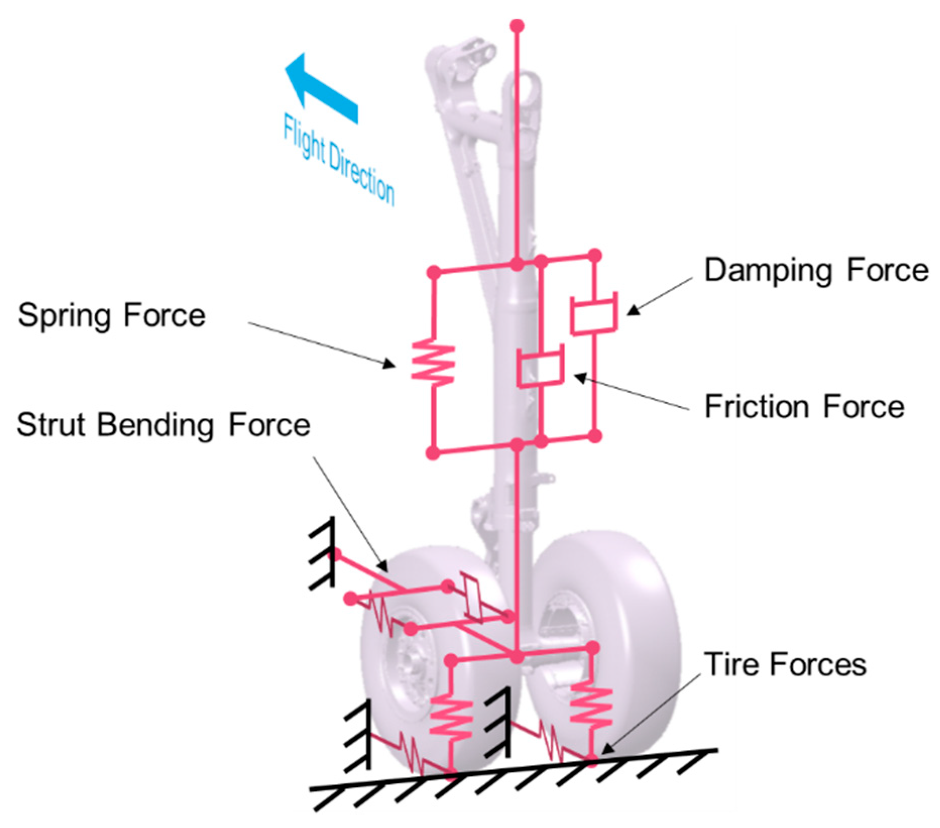
2.2. Dynamic Properties

The drop test should verify the dynamic parameters of the multi-body model as much as possible. Therefore, the fundamental model must be determined. It can be seen in Figure 2 that the spring and damping properties in the vertical and longitudinal directions are primarily determined by the characteristics of the two primary functional components, the shock absorber and the wheels. This model, known as the two-mass, multi-degree-of-freedom model [27,28], has been widely used in mathematical analysis and remains useful in the subsequent modeling of multi-body dynamics. It indicates that all spring and damping forces, as well as the shock absorber’s instroke, tire deflection, wheel rotation, and strut bending, must be reasonably considered. The dynamic model can be described in vertical and heading directions. They have both separate and coupled responses.

2.2.1. Vertical Properties

From the perspective of MBD modeling, in addition to the air spring force Fa, the oil-damping force Fh, and the friction force Ff, the axial force inside the buffer also needs to consider the structural limitation FL, which restricts the piston inside the shock absorber by the end-stop design.
The internal axial force FS is the sum of them, shown in Equation (1):
F S = F L + F a + F o + F f
The force FL is calculated as Equation (2):
F L = { K S 0 K ( S S m a x )     ( S < 0 ) ( 0 S S m a x ) ( S > S m a x )
where KL is the structure stiffness, S is the shock absorber travel, and Smax is the maximum stroke.
The air spring force Fa is calculated as Equation (3):
F a = A g a s [ p 1 ( V 1 V 1 A g a s S ) γ p a ]
where Agas is the effective compression area, p1 is the initial pressure, V1 is the initial volume of the gas chamber, γ is the gas polytrophic index, and pa is the atmospheric pressure.
The oil-damping force Fh is calculated as Equation (4):
F o = ρ h A o i l 3 S ˙ 2 C d 2 A d 2 | S ˙ |
where ρ h is the oil density, Aoil is the effective pressure oil area, Ad is the oil hole area, Cd is for the oil shrinkage coefficient, and S ˙ is the speed of shock absorber travel.
The bear friction force Ff corresponds to the normal force on the bearings, described by Equation (5):
F f = μ f | Q H | [ 2 ( A L 2 S ) A L 1 + S + 1 ] S ˙ | S ˙ |
where μf is the friction coefficient, QH is the normal bending force, AL2 is the distance between the upper and lower bearings, and AL1 is the distance between the lower bearing to the wheel axle center (WA).
The vertical motion also includes the tire compression, simplified as:
F T = m d f v ( δ )
where md is the dynamic factor, fv is the function of the load and deflection obtained from the test, and δ is the tire compression.

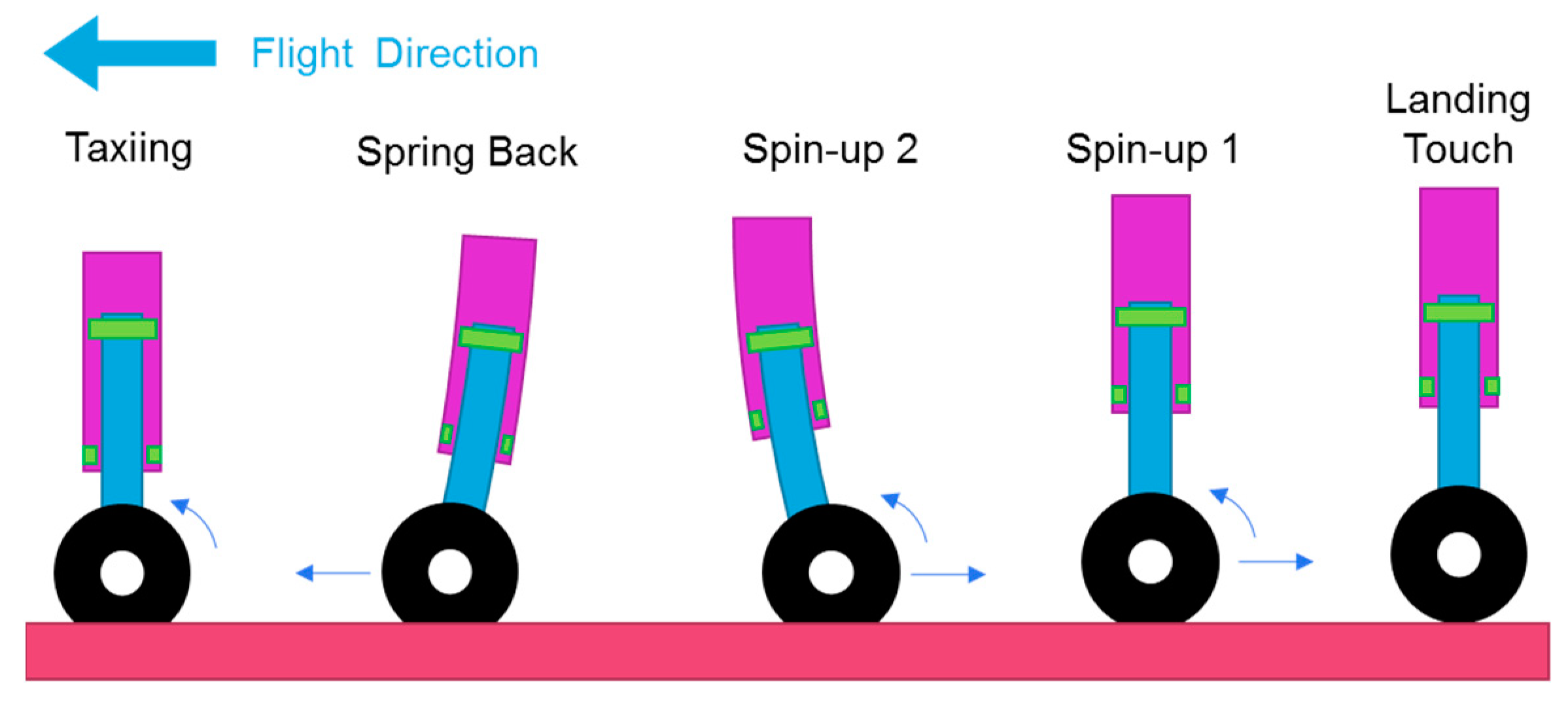
2.2.2. Longitudinal Properties

During high-speed landings, the tires’ contact with the ground causes a large amount of friction, which drives the wheels to rotate, as well as the strut’s rearward deformation, and then oscillation occurs backward and forward (gear walk). Because of the enormous and dramatic increases in tire friction, the two motions of wheel rotation and longitudinal oscillation are critical components of the landing dynamics that cannot be overlooked. However, because of the complex coupling influence of these two motions, as well as the nonlinear friction properties of tires, wheel inertia, inelastic mass, strut flexibility, structural damping, and other complicated elements, they have more difficult modeling procedures than the vertical.
These motions are represented in Figure 3 based on the time sequence, where the importance of strut bending and bearing contact simulation can be seen. Following the landing, the tires and ground friction caused by the wheels from their stationary position began to accelerate the rotation. The friction forces then pass to the wheel axle, causing the strut to bend backward. To a certain extent, when the relative friction has slowed, the stored elastic force drags the wheel back, demonstrating the forward and backward swinging characteristic of the wheels until all of the force has reached equilibrium.
In this process, it is necessary to include the ground friction and elastic and inertial forces at the wheel axle, which can be determined from the performance parameters of the landing gear and the state parameters of landing scenarios.
The tire friction force is determined based on the vertical force of the tire and the friction coefficient obtained by the slip ratio conversion, as shown in Equation (7):
D T = F T f l ( A E 2 )
where AE2 is the skip ratio and fl is the function of the friction coefficient.
The bending force QH is the normal force acting on the wheel axle’s center due to the bending deformation and structural damping of the strut, as described by Equation (8):
Q H = k q + C E q ˙
where k is the structural stiffness, CE is the structural damping coefficient, and q is the movement of the WA center.

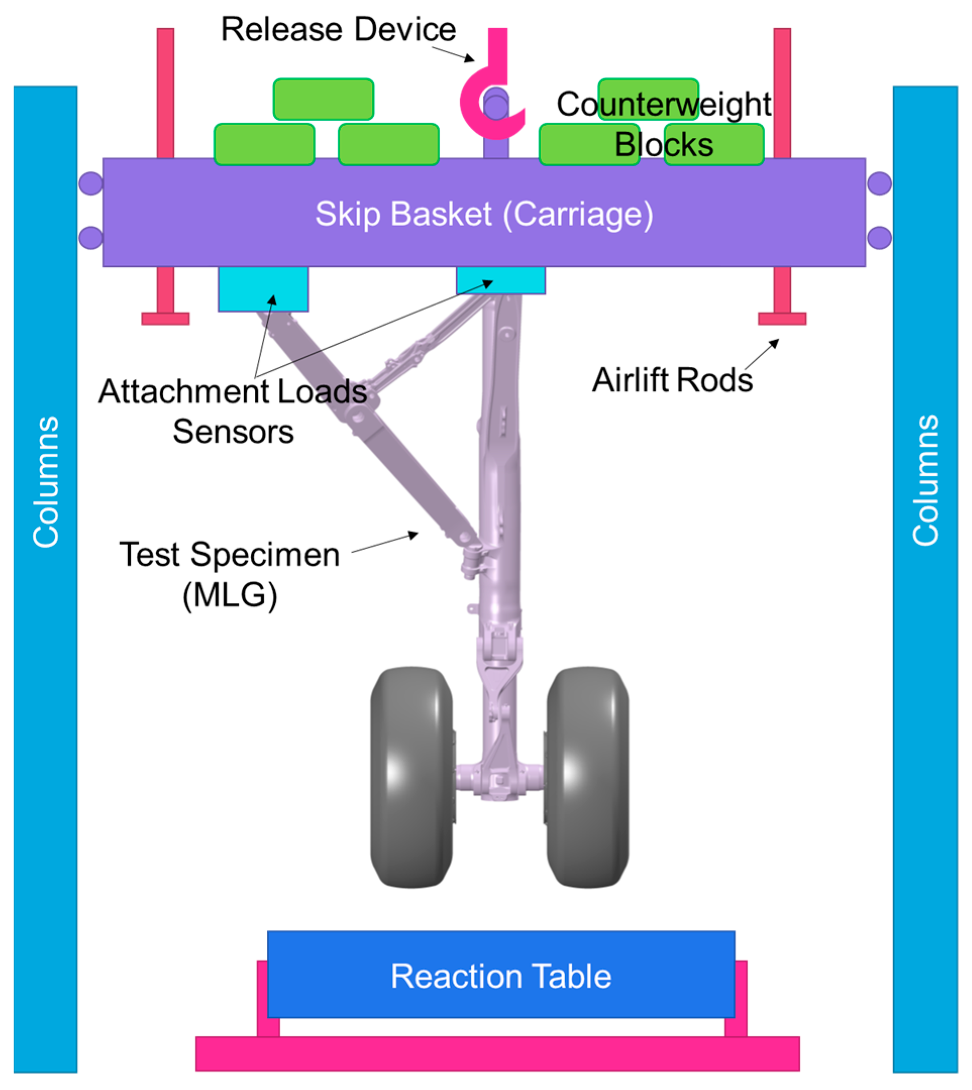
2.3. Experimental Drop Test

The drop test of this landing gear was carried out in a specific test rig, which included a column platform, mass skip basket, two impact reaction tables, airlift rods, a wheel speed-up system, and measurement equipment, as seen in Figure 4. The test piece was securely attached to the skip basket, which was suspended above by a releasable hook and carried metal blocks that regulated the drop weight. It was firstly elevated to a certain height in order to acquire a correct impact velocity while keeping the weight center just above the tire’s contact center. After the wheels sped up by a speed-up system of two additional drivable wheels, the unit was released and free felled vertically to the reaction table. During the drop impact process, high sample rates were used to measure and compute dynamic parameters such as loads, pressures, displacements, velocities, accelerations, temperatures, etc.
Traditionally, each impact reaction table is equipped with three-dimensional load sensors, which are mainly used to measure the vertical and longitudinal loads of tires on the ground contact (GC) point. A novel activity was that the load sensors were also equipped near the attachment points with the skip basket and used to measure the force on the wheel axle center (WA) by using a pre-analyzed loads transfer matrix so as to study the comprehensive longitudinal dynamic properties. The wheel axle loads are directionally used for the landing gear and airframe structure design, i.e., the spin-up and spring-back load cases, as opposed to ground contact loads. As such, this test is suitable and selected for the improved modeling method research in this paper to verify the simulation results by comparing the dynamic response, mainly the loads and the displacements.

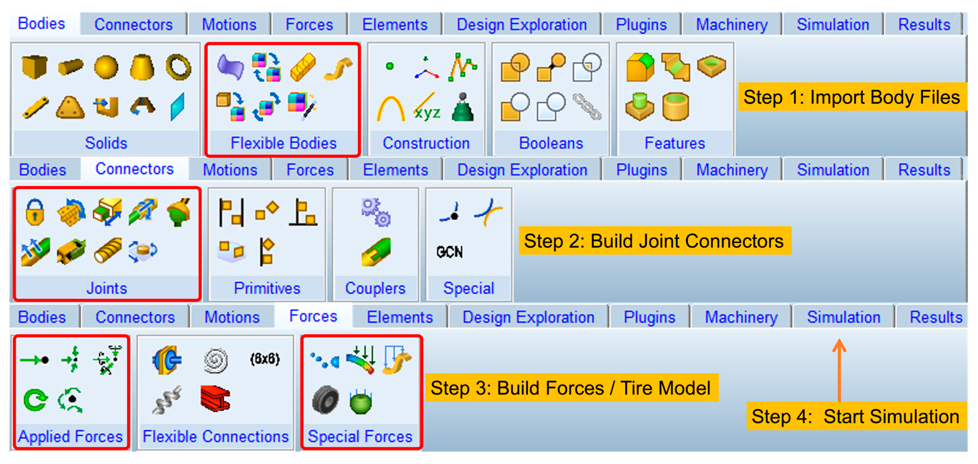
2.4. Multi-Body Dynamics Modeling

2.4.1. Theoretical Basis

A complex mechanical system that has several objects coupled by motion subsystems is referred to as a multi-body system. Multi-body system dynamics is a relatively new field of study based on classical mechanics, of which the main goal is to apply computer technology to the dynamics of complex systems analysis and simulation. It went through two phases: the dynamics of multi-body systems and computational multi-body systems based on the principles of classical rigid-body system dynamics. The latter is to deal with the challenges of flexible multi-body dynamics.
The flexible body could employ a finite element model with modal information, which includes a finite number of nodal degrees of freedom for a number of discretized cells, as well as nodal masses, moments of inertia, modal vibration shapes, and frequencies. The modal superposition approach is used to describe the object’s flexible deformations and displacements. The Cartesian coordinate system (x,y,z) describes the position, Euler angles ( ψ , θ , ϕ ) provide orientation, and the modal coordinates ( q 1 , q 2 , q M ) combine to form a generalized coordinate system ξ = ( x , y , z , ψ , θ , ϕ , q i ) T . The dynamical equations of each component of the multi-flexible body system can be deduced from the Lagrange equations. After computing the kinetic energy, potential energy, and energy loss function, the system’s differential equation can be obtained, with more complex details available in the ADAMS manual book or other MBD theoretical works.
It is well known that the mathematic equations for MBD problems are complicated and difficult to build or solve. However, it is well suited for computer engineering to deal with it without mechanical engineers needing to know too many profound details. Figure 5 depicts the graphical use interface for the program’s representative ADAMS V2017.2 and the simple modeling process of the landing gear system. The use of computer-aided modeling facilitates the rapid use of the integrated modeling function module in the window. Engineers can develop a suitable model and use the computer’s huge computational powers to successfully address massive and complex issues that were previously impossible or extremely difficult to solve.
The task of modeling and analyzing multi-body systems is thus transformed into a study of the mechanical properties of systems, as well as the reasonable use of software features, in order to develop a highly accurate and resilient simulation model. The internal characteristics of the landing gear were previously examined in Section 2.2, and the following phase focuses on the comprehensive modeling investigation of MSC.ADAMS V2017.2.

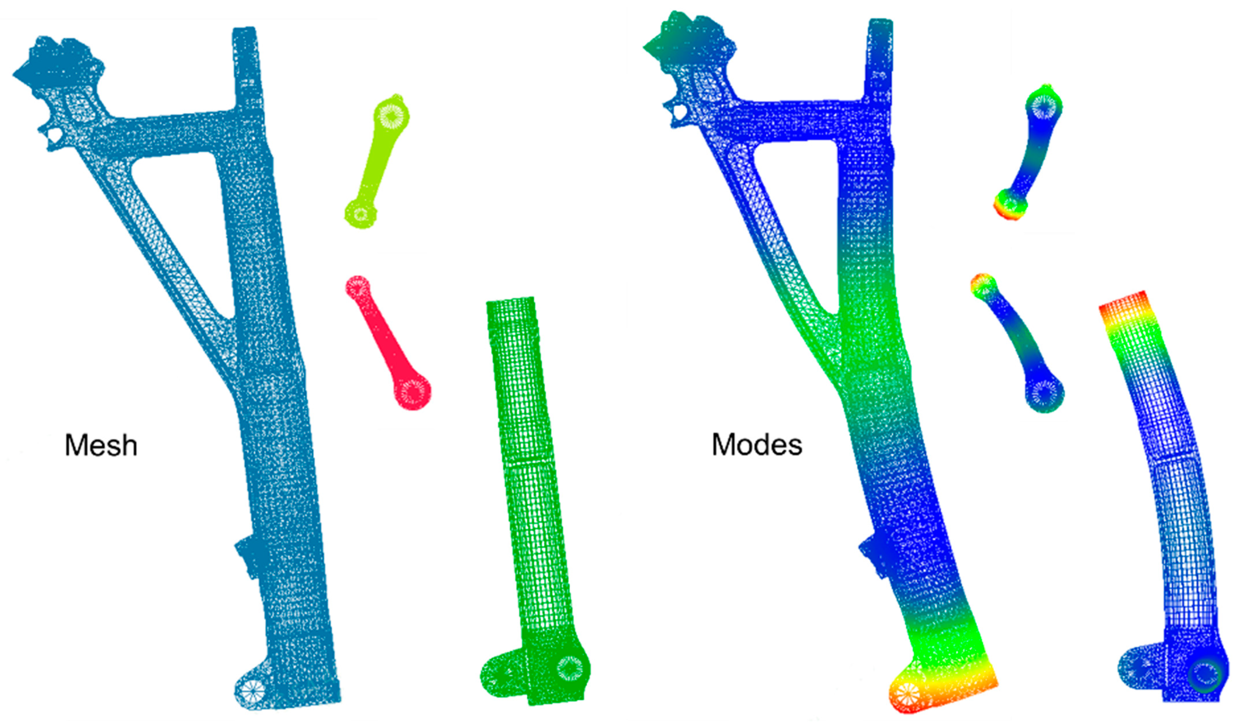
2.4.2. Flexible Bodies Modeling

The structural model of the landing gear could be simplified, as seen in Figure 1, in which only the main force-transmitting components are retained, including the outer cylinder, piston rod, wheel axle, wheels, and torque links. They are discretized to a finite element mesh using the geometry model from CATIA V5R18 and the FEM tools Altair Hypermesh 12.0. To precisely replicate the stiffness, these meshes match the actual structure forms and are assigned according to material type. The outside cylinder is composed of steel, and the remaining components are made of aluminum alloy. Their properties are presented in Table 1.
The ADAMS requires additional connection nodes between components, as well as preset action points for the air spring force and oil-damping force within the buffer. These connection points are linked to the finite element model mesh via a rigid element (RBE2). The connection points between the components are then defined as interface points for establishing the subsequent joint connections. By using the modal analysis module SOL103 of MSC.NASTRAN 2018.0, the FEM file (BDF format) of each component is then modal analyzed, and the modal neutral file (MNF format) is output and finally used by the ADAMS software V2017.2 to represent each flexible body. The mesh models and typical bending modes of the flexible bodies are shown in Figure 6.

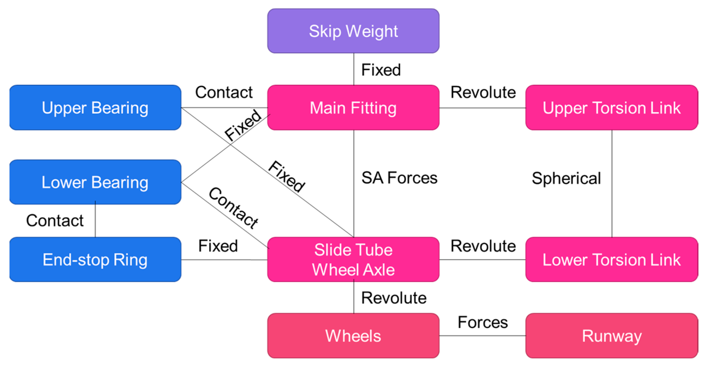
2.4.3. Joint Connector

A joint connector is a key component that connects two bodies and allows them to move relative to one another within established constraints and degrees of freedom. These are required for replicating real-world mechanisms and assemblies because they define the motion and interactions between various components. Engineers can produce more accurate and realistic mechanical system simulations by precisely specifying and modeling joints.
By only adopting the main parts of the landing gear, the number of joint connectors is reduced so as to make the simulation more efficient. In this model, the joint connectors of the fixed joint, revolute joint, and spherical joint were used to assemble the outer cylinder, the piston rod, the upper torsion link, the lower torsion link, and the bearings. As shown in Figure 7, the topological relationship demonstrates these joint connectors, as well as the bearing constraints, where the shock absorber (SA) forces connections of gas-spring and oil-damping, and the wheels and tires and the runway definition, as well as the components of the landing gear drop system, were assembled as one.

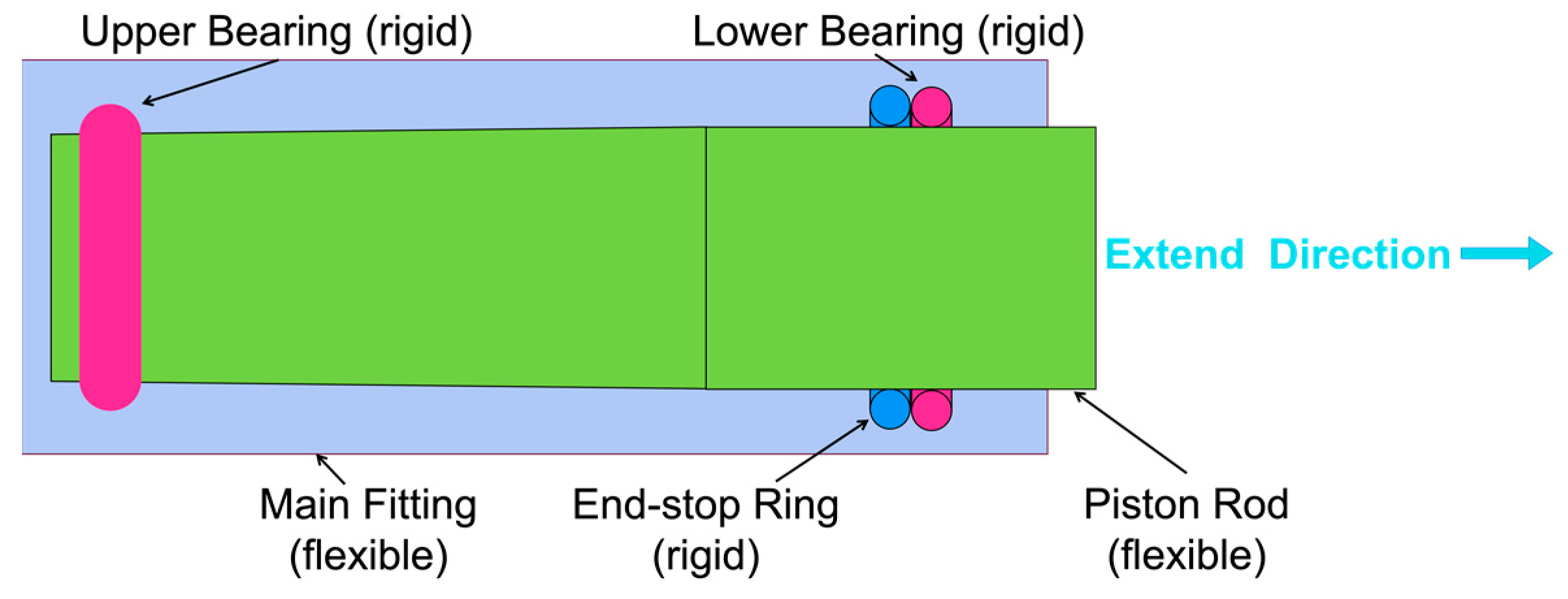
2.4.4. Bearing Contact

From the viewpoint of rigid-body modeling, the joint relation between the cylinder and piston could be treated as the revolute joint. While in the flexible bodies modeling, which is closer to the real world, the simulation of their movement’s relationship and force transfer shall also be changed. We tried a complicated but original way; that is, through the establishment of rigid bearings and a reasonable definition of the fixed joint, as well as the definition of the rigid–flex coupling contact between the bearings with the surface of the cylinder and piston rod. The schematic diagram of the principle of bearing modeling is shown in Figure 8.
The detailed connection principle between different parts and different surfaces can be described with the help of Figure 3. The upper bearing and lower bearing are simplified as a rigid circular bearing. Both of them are established with a fixed joint and a rigid–flex contact. The upper bearing is fixed at the upper end of the piston rod and so moves together with the piston rod while contacting the inner surface of the outer cylinder. The lower bearing is fixed at the lower end of the cylinder, contacting the outer surface of the piston. The lower bearing is modeled in a similar way, based on the real structural connection, creating a fixed pair with the cylinder and defining a rigid–flex contact with the inner surface of the piston rod. Moreover, this is so we can simulate the end-stop function that prevents the piston rod from extending out under the inflation pressure, which corresponds to the structural limiting force mentioned above. It also creates another rigid ring on the upper of the lower bearing, which was defined by its contact with the lower bearing and fixed joint with the piston rod.

2.4.5. Others

In addition to the bearing support and friction inside the shock absorber, there are also gas-spring forces and oil-damping forces between the strut outer cylinder and the piston, which shall be added. These forces are defined by the software component of the single component force according to the theoretical formulas and the force action point, which were constructed ahead of time during the modeling of the flexible body. During the simulation process, the relative distance and velocity of the two action points will be implemented and measured for converting the compression amount and compression velocity of the piston rod, which will then be referenced by the theoretical formulas to generate the required gas-damping forces.
To model the tires and runways, the tire definition file (TIR format) and the runway definition file (RDR format) are used, respectively, to define the basic parameters of the tires and the ground. They are as follows: the tire radius, vertical stiffness, friction system, and other tire parameters, as well as the runway’s position, such as the height, width, and length. The complex tire component is utilized to perform modeling operations such as the road surface object, tire object, wheel axle connection position, and direction.

3. Results and Discussion

3.1. MBD Model and Simlation Case

According to the technique and method described above, the appearance of the completed MBD model is displayed in Figure 9, where the tires and runway—while being defined in a file rather than being imported from a 3D model—appear to be highly intuitive. Furthermore, an in-virtual counterweight (skip basket) on top of the model is not shown for graphical simplicity, and a lift force equal to the same weight is set at the counterweight to imitate the lift force used in the test. Because of the complexity of the tires’ friction properties and their significant influence on longitudinal loads, the friction coefficients measured during the test were used as inputs to the tire definition file. The simulated case information was the same as the actual test case as follows: drop mass of 35,000 kg, sinking speed of 3.15 m/s, wheel speed of 981 r/min, pitch angle of 0° (level landing), and an ambient temperature of 22°.

3.2. Simulation Results

Figure 10 depicts the animation results produced after executing the simulation command, allowing the structure’s flexible deformation phenomenon (gear walk) to be visualized. The landing gear strut bends backward in 0–0.1s, reaches maximum deformation in 0.07 s, bounces forward in 0.1–0.2 s, and then bends forward in 0.2 s to achieve maximum deformation. The tire and the shock absorber compressed at the beginning and then rebounded, which was more obvious compared with the tire deformation, while the subsequent rotations of the torque links were more obvious.
The kinematic characteristics of the landing gear longitudinal deformation and vertical deformation are both consistent with the dynamic response characteristics of the loads as well. As shown in Figure 11, the wheel axle point’s longitudinal load reached its maximum value at 0.07 s, corresponding to the maximum spin-up moment, and the reverse maximum value was at 0.13 s, corresponding to this maximum spring-back moment. The changes in the compressions of the shock absorber compression and tire were synchronized with the vertical load, with the shock absorber compression reaching a maximum value of 407 mm at 0.22 s and the tire compression reaching a maximum value of 120 mm at 0.21 s. In conjunction with Suresh’s study [1], it can be found that the gear-walk form of the longitudinal load’s response is similar, except for the difference in the frequency. The reason may be the difference in geometry size or the horizontal speed.
The most important consideration is that, compared to the drop test, the deviations of the key responses are all small, including the loads, the compression, and the inner pressures. In severe load cases, such as the maximum spin-up, maximum spring back, and maximum vertical, the time moments and load values are in good agreement, such that the deviations are within 8%. This first agreement between the experimental and numerical results for a specific configuration means that the method in this study could have the possibility to undergo a dedicated experimental campaign for its verification. This topic will be addressed in future studies.
According to the theoretical formulas of axle point load and tire load described before, the simulation results show that the gear walk phenomenon is related to the structural flexibility phenomenon, and the coupling effect with the wheel rotation motion is also simulated. Compared with the traditional two-mass multi-degree-of-freedom mathematical modeling solution method [27], the fluctuating characteristics presented by the load results, such as the wave, frequency, etc., are similar. For the bearing friction, although there is no direct comparison of the experimental measurement data, according to the composition of the axial force inside the buffer (air pressure, oil pressure, and bearing friction), as well as the comparison of the shock absorber compression and speed, combined with the results of Sanjay Baskaran [26], it can be assumed that the loads obtained from the simulation are also credible.
When the aforementioned findings and the discussion are combined, it becomes clear that the developed landing gear multi-body model can replicate the landing gear drop shock test. Good agreement findings are obtained regardless of the vertical or longitudinal parameters, demonstrating the comprehensiveness of the model outputs. Furthermore, because of the intuitive animation effect, the multi-body simulation results of animation based on the virtual prototype technology can aid engineering designers in identifying and resolving issues more effectively, indicating that the technology has a promising future.

3.3. Parameter Influence Study

Examining the research methodology for this paper, we first determined, from the theoretical characteristics of the landing gear system, the significant influence of structure stiffness and bearing contact in the dynamic characteristics of the landing gear drop test. We then improved the modeling approach in accordance with these findings, and by comparing the current method with the test data, we were able to demonstrate its viability. To further highlight the significance of taking into account the flexible bodies and bearing contact, we are also required to look at how much the simulation results would change if these two factors were not properly taken into account based on the modeling described above. In order to compare, two more simulation models were created.

3.3.1. Structure Flexibility Influence

In this model, all the flexible bodies were turned into rigid bodies by turning the setting of inertia modeling from coupling to rigid. It is similar to the traditional multi-rigid model way of importing rigid bodies instead of using the modal neutral file as the flex-bodies input. In this traditional way, the outer cylinder and piston rod are connected by the revolute joint; it is not possible to consider the deformation of the flexible body in real situations, as well as the distribution of the bending forces on the upper and lower bearings.
As the results show in Figure 12a, it can be found that the longitudinal load at the wheel axle has obvious changes: The moment of maximum spin-up is advanced from 0.071 s to 0.046 s, and the load is decreased from 241 kN to 178 kN. Meanwhile, the moment of the maximum spring back is advanced from 0.132 s to 0.0975 s, and the load is decreased from 259 kN to 78 kN. The most interesting finding is in Figure 12b. The gear walk loads for the wheel axle point loads were weaker—from 5 waves to 2 waves—and were approximately equal to the tire grounding point loads. In Figure 12c, the maximum vertical load moment changed more dramatically, from 0.15 s to 0.27 s, which means the longitudinal load, as well as the total force at the maximum vertical case, changed dramatically. Moreover, the according shock absorber travel changed dramatically, indicating that the loads transfer to the attachment point of the aircraft airborne will also change dramatically, too.
However, it is also proved that if one is more concerned about the vertical drop loads during the conceptual design phase, using rigid-body modeling to acquire preliminary design results is adoptable and efficient.

3.3.2. Bearing Contact Influence

Bearings support the outer cylinder in the longitudinal direction, namely the normal forces perpendicular to the axis of the shock absorber, as shown in Figure 3. It is obvious that the position of bearing contact must be set accurately and strictly according to the design scheme; otherwise, it will affect the force transmission path and bending stiffness of the landing gear. The bearing forces also contain the friction forces along the axis direction. We then focused on investigating the impact of friction influence.
In this model, we modified the preset column friction to none based on the rigid–flex contact parameters. As a result, Figure 13 displays the vertical WA loads, and the bearing support forces change. The vertical WA loads vary somewhat between 0.08 s and 0.3 s. The bearings’ support forces in the longitudinal direction are virtually constant. It demonstrates that the friction influence is less than the structural flexibility. Thus, bearing contact modeling is more necessary for flexible body connections than friction simulation. However, if we want to forecast exact responses, such as comprehensive design phrases, the friction should be carefully examined.

4. Future Direction

According to the findings of the preceding study, the improved modeling approach in this work can improve the multi-body simulation of the landing gear drop test, potentially supporting future expansion by its extensional virtual modeling technology and user-friendliness, as well as helping landing gear design engineers to construct better designs.
Two aspects listed below can be examined for further investigation.

4.1. MBD Modeling

Using more complex simulation methods, such as a more detailed tire model, flexible bearings, flexible joint connectors, tire rubber characteristics, runway roughness, and so on, makes the simulation more realistic. Alternatively, instead of time-consuming contact simulation, use a reasonable simplification, such as optimizing the FEM size or the tire friction model, to improve the simulation’s efficiency, which is of great interest to engineers dealing with a large number of analytical conditions.

4.2. Landing Loads Design

Aside from vertical and longitudinal load designs, lateral loads may be further investigated using MBD technology, which can lessen the difficulty of dynamic modeling analysis when compared to traditional mathematical modeling. Some fighters’ main landing gear with lateral inclination will have higher lateral loads, which, combined with longitudinal loads, will result in greater bending forces on the airframe. Even landing gear without lateral inclination, such as the landing gear described in this study, is found to be subjected to small lateral loads in both the test and simulation.

Author Contributions

Conceptualization, W.L. and Y.W.; methodology, W.L.; software, W.L.; validation, W.L.; formal analysis, W.L.; writing—original draft preparation, W.L.; writing—review and editing, Y.W.; supervision, Y.W. All authors have read and agreed to the published version of the manuscript.

Funding

The APC was funded by the Shanghai Aircraft Design and Research Institute, China Commercial Aircraft Corporation, Shanghai 201210, China.

Data Availability Statement

The raw data supporting the conclusions of this article will be made available by the authors on request.

Conflicts of Interest

The authors declare no conflicts of interest.

References

  1. Suresh, P.; Sura, N.K.; Shankar, K.; Radhakrishnan, G. Synthesis of landing dynamics on land-base high performance aircraft considering multi-variate landing conditions. Mech. Based Des. Struct. Mach. 2023, 51, 3945–3964. [Google Scholar] [CrossRef]
  2. Schmidt, R.K. The Design of Aircraft Landing Gear; SAE International: Warrendale, PA, USA, 2021. [Google Scholar]
  3. Pritchard, J. Overview of landing gear dynamics. J. Aircr. 2001, 38, 130–137. [Google Scholar] [CrossRef]
  4. Fang, W.; Zhu, L.; Wang, Y. Landing Performance Study for Four Wheels Twin Tandem Landing Gear Based on Drop Test. Aerospace 2022, 9, 334. [Google Scholar] [CrossRef]
  5. EASA. Certification Specifications and Acceptable Means of Compliance for Large Aeroplanes, CS-25 Amendment 27; EASA: Cologne, Germany, 2023.
  6. Krüger, W.R.; Morandini, M. Recent developments at the numerical simulation of landing gear dynamics. CEAS Aeronaut. J. 2011, 1, 55–68. [Google Scholar] [CrossRef]
  7. Correia, D.; Ferreira, A. Aircrafts on-ground dynamics models and simulation software: State-of-the-art. Sustainability 2021, 13, 9147. [Google Scholar] [CrossRef]
  8. Taylor, P.; Hanson, L.; Barnes, T. A Brief History of Aircraft Loads Analysis Methods. In Proceedings of the 44th AIAA/ASME/ASCE/AHS/ASC Structures, Structural Dynamics, and Materials Conference, Norfolk, VA, USA, 7–10 April 2003. [Google Scholar] [CrossRef]
  9. Norwood, D.S.; Chichester, R.H. Full scale aircraft drop test program for the F-35C carrier variant. In Proceedings of the 56th AIAA/ASCE/AHS/ASC Structures, Structural Dynamics, and Materials Conference, Kissimmee, FL, USA, 5–9 January 2015. [Google Scholar] [CrossRef]
  10. Caijun, X.; Xiuli, X.; Wengang, Q. Research on the performance of buffer for landing gear based on the drop test. J. Vibroeng. 2012, 14, 794–804. [Google Scholar]
  11. Wang, H.; Wu, D.; Wang, F.; Ren, H. A method for determining the horizontal impact load based on the rotational speed of the aircraft’s wheel in a landing gear drop test. Int. J. Crashworthiness 2018, 23, 627–634. [Google Scholar] [CrossRef]
  12. Gan, S.; Fang, X.; Wei, X. Parametric Analysis on Landing Gear Strut Friction of Light Aircraft for Touchdown Performance. Appl. Sci. 2021, 11, 5445. [Google Scholar] [CrossRef]
  13. Kang, B.H.; Kim, B.G.; Choi, S.B. Aircraft landing gear system with magnetorheological shock strut: Performance evaluation via drop test. J. Intell. Mater. Syst. Struct. 2023, 34, 1471–1485. [Google Scholar] [CrossRef]
  14. Currey, N.S. Aircraft Landing Gear Design: Principles and Practices; American Institute of Aeronautics and Astronautics: Washington, DC, USA, 1988. [Google Scholar]
  15. Lernbeiss, R.; Ploechl, M. Simulation model of an aircraft landing gear considering elastic properties of the shock absorber. Proc. Inst. Mech. Eng. Part K J. Multi-Body Dyn. 2007, 221, 77–86. [Google Scholar] [CrossRef]
  16. Zhang, Z.; Wei, X.; Ye, Q. Heading Load Dynamic Simulation of Landing Gear Test. In The Proceedings of the 2018 Asia-Pacific International Symposium on Aerospace Technology (APISAT 2018); Springer: Singapore, 2019; pp. 1469–1476. [Google Scholar]
  17. Richards, P.W.; Erickson, A. Dynamic Ground Loads Analysis Using Detailed Modeling of Landing Gear and Aircraft Aeroservoelastics. In Proceedings of the AIAA SciTech 2019 Forum, San Diego, CA, USA, 7–11 January 2019. [Google Scholar] [CrossRef]
  18. McDonald, M.; Richards, P.W.; Walker, M.; Erickson, A.J. Carrier Landing Simulation using Detailed Aircraft and Landing. In Proceedings of the AIAA SciTech 2020 Forum, Orlando, FL, USA, 6–10 January 2020. [Google Scholar] [CrossRef]
  19. Orlandea, N.V. Multibody systems history of ADAMS. J. Comput. Nonlinear Dyn. 2016, 11, 060301. [Google Scholar] [CrossRef]
  20. Zhang, L.; Xue, C.J. A Landing Gear Drop Dynamic Simulation based on the LMS. Virtual. Lab. Appl. Mech. Mater. 2011, 55–57, 684–687. [Google Scholar] [CrossRef]
  21. Hewlett, J. Methods for Real-Time Simulation of Systems of Rigid and Flexible Bodies with Unilateral Contact and Friction; McGill University: Montreal, QC, Canada, 2020. [Google Scholar]
  22. Kadam, M.; Sathish, S.; Bujurke, A.; Joshi, K.; Gopalsamy, B. Dynamics of Articulated Landing Gear in Tail-Down Landing Condition. In Machines, Mechanism and Robotics: Proceedings of iNaCoMM 2017; Springer: Singapore, 2019; pp. 195–206. [Google Scholar]
  23. Huang, M. Research on loads applied on powered wheels and struts of civil aircraft at touchdown. Proc. Inst. Mech. Eng. Part C J. Mech. Eng. Sci. 2022, 236, 840–851. [Google Scholar] [CrossRef]
  24. Stachiw, T.; Khouli, F.; Langlois, R.G.; Afagh, F.F. Landing gear mechanical network synthesis for improving comfort at landing considering aircraft flexibility. J. Aircr. 2021, 58, 1242–1253. [Google Scholar] [CrossRef]
  25. Zhang, M.; Wei, X.; Yang, Z.; Shi, X. Six-wheel trolley type landing gear ground load analysis study. Xibei Gongye Daxue Xuebao/J. Northwestern Polytech. Univ. 2022, 40, 1090–1099. [Google Scholar] [CrossRef]
  26. Baskaran, S.; Sivaprakasam, S. Friction analysis of aircraft landing gears due to landing impact. Proc. Inst. Mech. Eng. Part J J. Eng. Tribol. 2022, 236, 274–283. [Google Scholar] [CrossRef]
  27. Gao, Z. Aircraft Design Manual: Volume 14, Take-Off and Landing System Design; Aviation Industry Press: Beijing, China, 2001. [Google Scholar]
  28. Pecora, R. A Rational Numerical Method for Simulation of Drop-Impact Dynamics of Oleo-Pneumatic Landing Gear. Appl. Sci. 2021, 11, 4136. [Google Scholar] [CrossRef]
Figure 1. Landing gear structural parts diagram.
Aerospace 11 00543 g001
Figure 2. Landing gear dynamic properties.
Aerospace 11 00543 g002
Figure 3. Wheel rotation and strut bending.
Aerospace 11 00543 g003
Figure 4. Landing gear drop test schema.
Aerospace 11 00543 g004
Figure 5. ADAMS graphical user interface.
Aerospace 11 00543 g005
Figure 6. Finite meshes and typical bending modes.
Aerospace 11 00543 g006
Figure 7. Connection topology schema.
Aerospace 11 00543 g007
Figure 8. Bearing contact.
Aerospace 11 00543 g008
Figure 9. MBD model’s appearance.
Aerospace 11 00543 g009
Figure 10. Kinematic animation results.
Aerospace 11 00543 g010
Figure 11. Dynamic response results: (a) vertical loads, (b) longitudinal loads, (c) shock absorber stroke, and (d) shock absorber inner pressure.
Aerospace 11 00543 g011
Figure 12. Strut flexibility influence: (a) longitudinal WA loads; (b) longitudinal loads of WA and GC; (c) vertical WA loads.
Aerospace 11 00543 g012
Figure 13. Bearing frictional influence: (a) vertical WA loads; (b) bearing support loads.
Aerospace 11 00543 g013
Table 1. Material properties.
Material NameElastic Modus
(GPa)
Poisson’s Ratio
(Dimensionless)
Density
(kg/m3)
300M Steel2050.277850
Aluminum Alloy700.332810
Disclaimer/Publisher’s Note: The statements, opinions and data contained in all publications are solely those of the individual author(s) and contributor(s) and not of MDPI and/or the editor(s). MDPI and/or the editor(s) disclaim responsibility for any injury to people or property resulting from any ideas, methods, instructions or products referred to in the content.

