Article

Study on Heat Transfer Characteristics of Jet Impingement of Turbine Bending Surface

1
AECC Hunan Aviation Powerplant Research Institute, Zhuzhou 412000, China
2
College of Energy and Power Engineering, Nanjing University of Aeronautics and Astronautics, Nanjing 210016, China
*
Author to whom correspondence should be addressed.
Aerospace 2024, 11(7), 554; https://doi.org/10.3390/aerospace11070554
Submission received: 10 May 2024 / Revised: 16 June 2024 / Accepted: 24 June 2024 / Published: 5 July 2024

Abstract

:
The architecture of aeroengine air-cooling system channels is notably intricate, with impingement heat transfer standing out as a critical process amidst the complexity. This study delves into the casing annular cavity’s structure, examining the influence of flow and structural parameters on heat transfer characteristics. Experimental findings have revealed a trend towards more uniform temperature distributions across the impingement target plate as the relative impingement distance (H/d) increases, under a constant impingement Reynolds number (Rej). Notably, an impingement angle (β) of 90° yields optimal heat transfer effects on the target surface. Furthermore, a higher impingement hole consistency (Is) correlates with a lower and more uniform temperature distribution across the target plate. Additionally, escalating the crossflow ratio (mc/m) results in a decline in the temperature at the impingement stagnation point and a corresponding rise in the heat transfer coefficient.

1. Introduction

The turbine casing functions as a conduit for cooling gas and also serves as a crucial load-bearing structure in the engine. It has an intricate internal structure and numerous cooling techniques, among which impingement cooling is particularly prominent due to its high cooling effectiveness. Impingement cooling has a high local heat transfer coefficient and stronger convective heat transfer can be achieved by changing structural or aerodynamic parameters. The flow and heat transfer of impingement jets are complex, and numerous studies have been conducted on the mechanisms and heat transfer characteristics, mostly focus on thermal protection of turbine blades [1].
Many scholars have conducted extensive research on impingement cooling. For the heat transfer research of impingement cooling, three main research directions can be identified: the research on the geometric parameters of impingement structures, the research on the flow parameters of incoming fluid, and the research on the jet target plate or overall structure. There is a wide range of research on the influence of impingement structure on heat transfer effect. G. Xie et al. [2] studied the effects of geometrical parameters on overall cooling effectiveness of the flat plate with impingement cooling. The results indicate that overall cooling effectiveness is significantly improved by adding impingement. At the same blowing ratio, the overall cooling effectiveness decreases as the gap distance increases for staggered arrangements. For overlapped arrangements, the cooling effectiveness peaks at H/d = 10. Ü. Tepe et al. [3] used extended jet holes to conduct experimental and numerical investigation of jet impingement cooling and elucidated the effect of extended jet holes on the heat transfer performance of the in-line array jet impingement configuration. Average and local Nusselt number distributions, pressure drop of the system, and flow characteristics were obtained under different dimensionless jet-to-jet spacing, dimensionless jet plate-to-target plate spacing, and dimensionless target plate width. W. Florschuetz et al. [4,5,6] found that the non-dimensional channel height (H/d = 1−3; H is the channel height or jet plate-to-impingement surface spacing, d is the jet hole diameter) has little effect on the mean Nusselt number, and small hole spacing can improve local heat transfer but has little effect on the mean heat transfer effect. The effect on initial crossflow by array impingement was analyzed and the functional relationship between Nusselt number, Reynolds number, shape factor, and other factors was obtained. Z. Zhang et al. [7] conducted experimental research on impingement cooling with single and double rows of holes in a semi-confined channel, and obtained the effects of flow parameters and geometric parameters such as Reynolds number, hole spacing, diameter ratio, and impact spacing ratio on local heat transfer characteristics. M. León De Paz et al. [8] built a mathematical model on the in-line array of impinging jets of diameters 0.5 mm and 0.25 mm. The numerical simulation shows that the overall average heat transfer coefficient increases by 63% at a constant flow and small jets. While at a fixed pressure drop across the vane, the heat transfer coefficient increases by 34.3%. Recently, M. Attalla [9] studied the effects of Reynolds number, jet-to-plate distance, and inclination angle on the heat transfer efficiency of a horizontal flat plate, and found that the maximum heat transfer point efficiency on the target plate changes with the change of inclination angle. K. Wang et al. [10] studied heat transfer characteristics on impingement cooling with exit holes using numerical simulation. The results show that the smaller the relative impingement distance, the higher the average Nusselt number of the target plate. L. Wang et al. [11] studied array jet impingement with different hole spacings. The results show that the heat transfer characteristics are the best when the hole spacing ratio is from three to five.
Meanwhile, many scholars have also studied and analyzed the influence of flow parameters on the impingement cooling process. M. Shin et al. [12] conducted experiments and numerical simulations and found the average heat transfer coefficient at the target surface increases with the jet Reynolds number. J. J. Otero Perez [13] studied turbulent multi-jet impingement cooling flows using large-eddy simulations (LES). The results show that large crossflow intensities bring a jet deflection which reduces the maximum in the Nusselt number distribution and increases the heat transfer in the areas of the wall less affected by the jet impingement. M. Forster and B. Weigand [14] conducted an experimental and numerical heat transfer investigation of an impingement jet array with a concave target plate. The results show that crossflow decreases the stagnation point heat transfer and overall heat transfer but homogenizes the local heat transfer distribution. Smaller separation distance will improve the crossflow effects and increase the heat transfer effect. G. Miao et al. [15] conducted studies on the flow structure of concave surface with inclined impingement in limited space, finding that the separation between fluid and target surface in the flow direction is earlier than the other side, bounded by the stagnation region. M. Waehayee et al. [16] studied the flow and heat transfer characteristics of in-line impinging jets in crossflow. The study shows that crossflow can significantly improve the jet impingement cooling effect under the studied conditions. Q. Lu et al. [17] purposed a rotating jet impingement cooling system to achieve effective cooling and investigated the effects of the Reynolds number, the pipe rotation speeds, and the fluid properties on the jet impingement cooling performance.
There are also many studies on the influence of target structure or overall structure on heat transfer effect. D. Qiu et al. [18] investigated the effects of pin-fin arrangement and jet Reynolds number on heat transfer enhancement and flow characteristics of a concave confined jet impingement cooled surface conjugated with pin-fins, and found that the appearance of the pin-fin plays a positive role in heat transfer enhancement and uniformity. W. He et al. [19] studied the effects of turning angle and turning internal radius on channel impingement cooling for a novel internal cooling structure. They found that turning angle and turning internal radius have a significant effect on the jet form and heat transfer effects. The smaller turning angle leads to stream-wise counter-rotational vortices and high turbulence intensity. Increasing turning internal radius transfers the jet form from impingement jet to laminar layer attaching the target surface with low heat transfer. F. B. Ahmed et al. [20] simplified the jet impingement cooling structure, which has typical circumferential bending circular section, into a model featuring a smooth target plate impacted by a horizontal short straight pipe vertically. L. Ma [21] found that the turbine case structure and the orifice have a significant impact on the development of the impinging jet, which changes local and mean heat transfer effects. J. Ortega-Casanova et al. [22] studied the surface variations along the plates and obtained that the average heat transfer efficiency of dimpled and bumped plates is significantly higher than that of a flat target plate using numerical simulation. Y. Jia et al. [23] conducted extensive experimental studies on the heat transfer characteristics of two rows of aligned jet holes on a concave surface in a wing leading edge. The results show that heat transfer performance at the jet-impingement stagnation point with two rows of aligned jet holes is the same as that with a single row of jet holes. S. Yamagami et al. [24] studied the local heat transfer of round water jet impingement on upward-facing and downward-facing static plates, and obtained that the heat transfers between upward-facing and downward-facing surfaces are the same at a downward-facing surface with flow rate from 1.2 times to twice that of the upward-facing surface. P. Sriromreun et al. [25] studied the impinging jets heat transfer on a dimpled surface, and obtained the effects of dimples on the heat transfer enhancement. J. K. Yan et al. [26] studied the heat transfer characteristics of array jet impingement with oblong pin-fins. They found that at the same Reynolds number, when the diameter of the impingement holes decreases, the mass flow rate of the cooling-air decreases by 33% and the average heat transfer coefficient drops by 10%.
With the development of high power density electronics and computing systems, jet impingement heat transfer technology is widely used in the cooling of electronic components due to its high heat transfer coefficient and easy processing. A. Haji Hosseinloo et al. [27] studied a new double-chamber jet impingement cooling system and tested its performance in harsh conditions. S. N. Joshi et al. [28] studied the performances of submerged two-phase jet impingement cooler in combination with porous coated heat spreaders and multi-jet orifices; they evaluated the cooling performance of four kinds of porous coated structures under 5 K supercooling using R-245fa (Honeywell Inc., Charlotte, NA, USA) as the coolant. The results show that the pin-fin heat spreader has the best heat transfer performance, followed by open tunnel (OPT), closed tunnel (CLT), and flat heat spreader.
In sum, thorough and detailed studies regarding the impingement heat transfer of a plane target plate have been conducted, and numerous results have been obtained. However, there are few studies on impingement heat transfer on a curved target plate. This study, focusing on the cooling structure of a new type of aero-engine casing, designs a curved target impingement cooling structure and carries out test research on the impact of geometric parameters and aerodynamic parameters on the impingement heat transfer of the curved target surface. The results provide theoretical support for the design of the cooling structure for a new type of aero-engine casing.

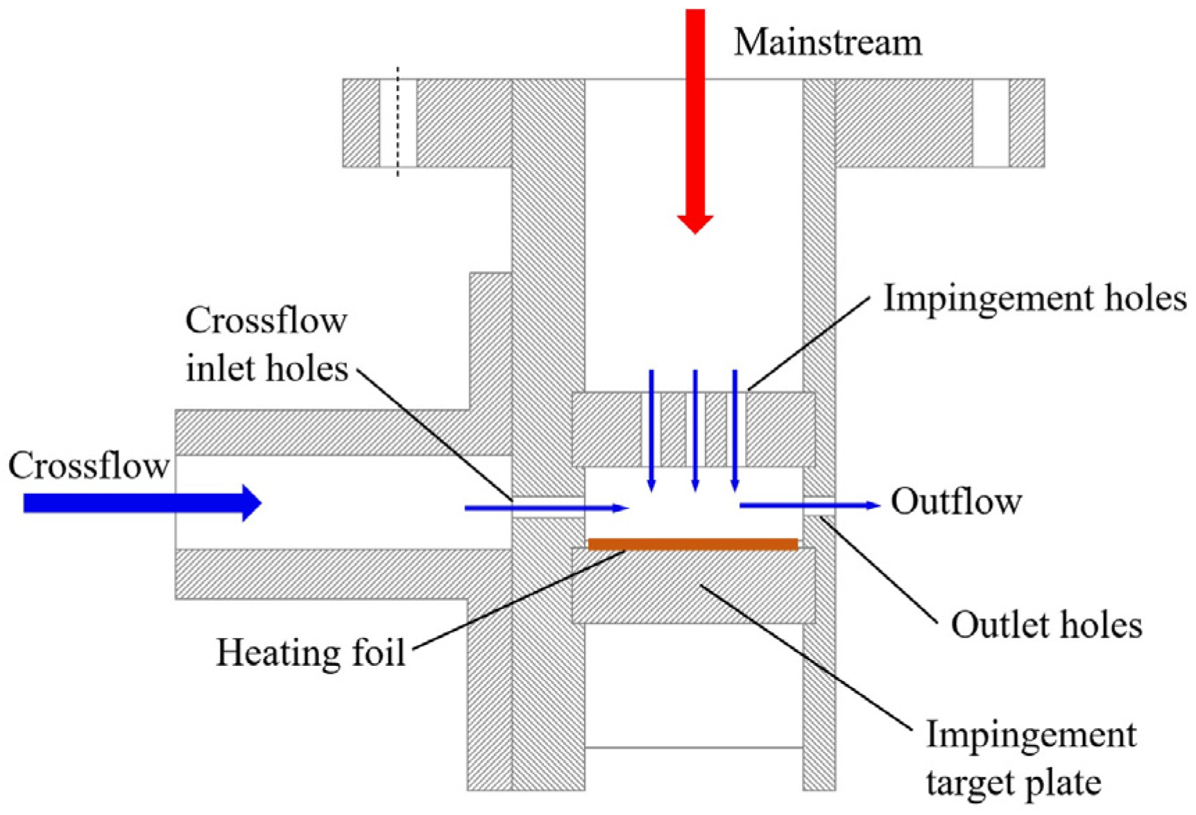
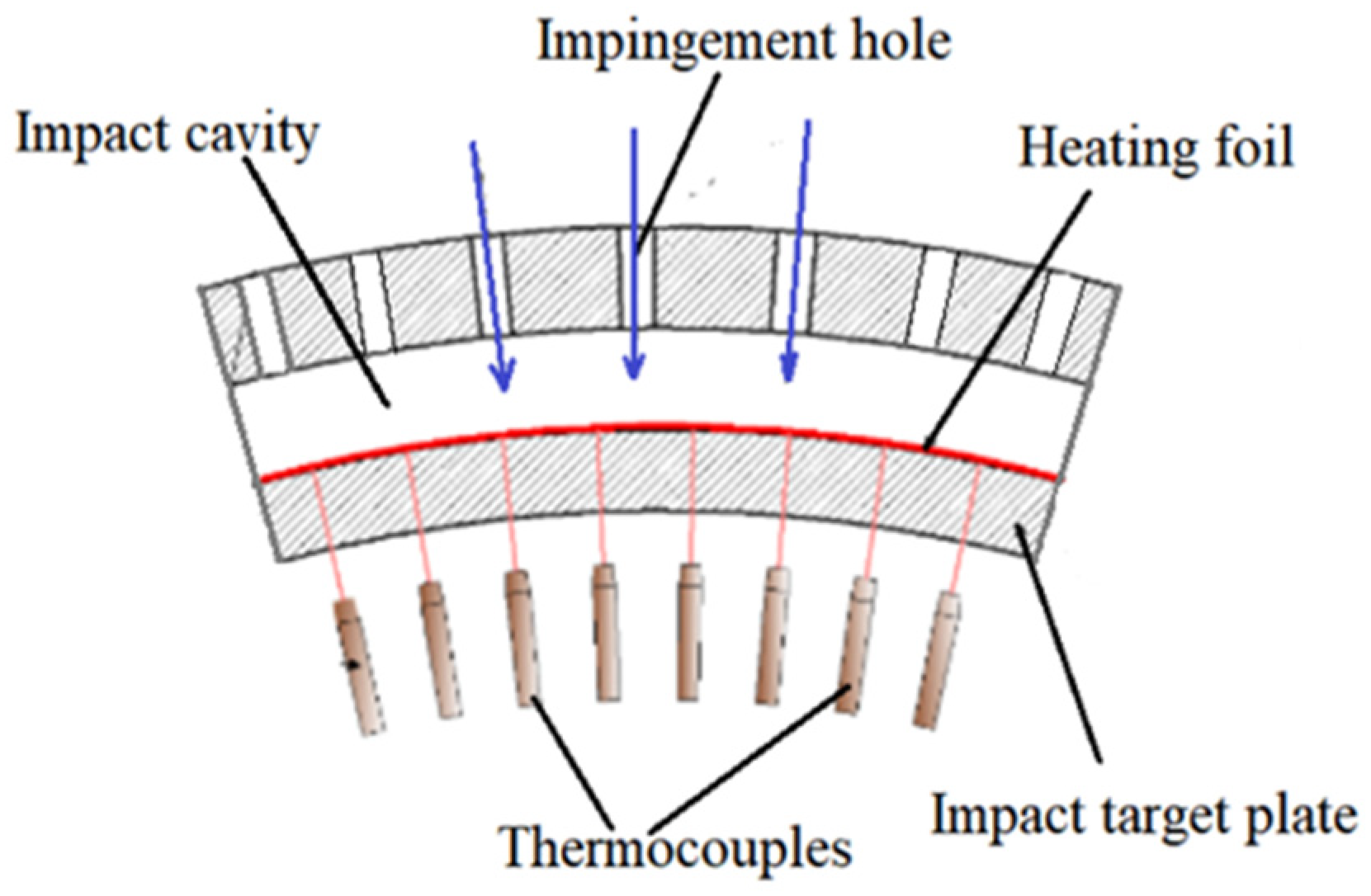
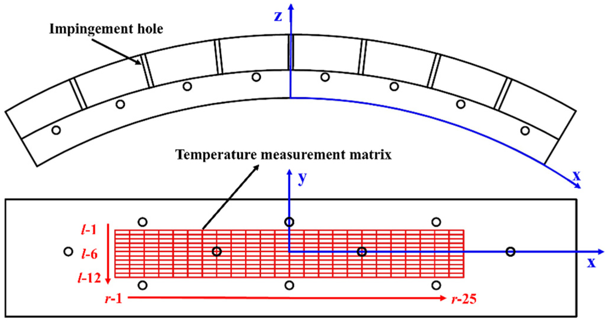
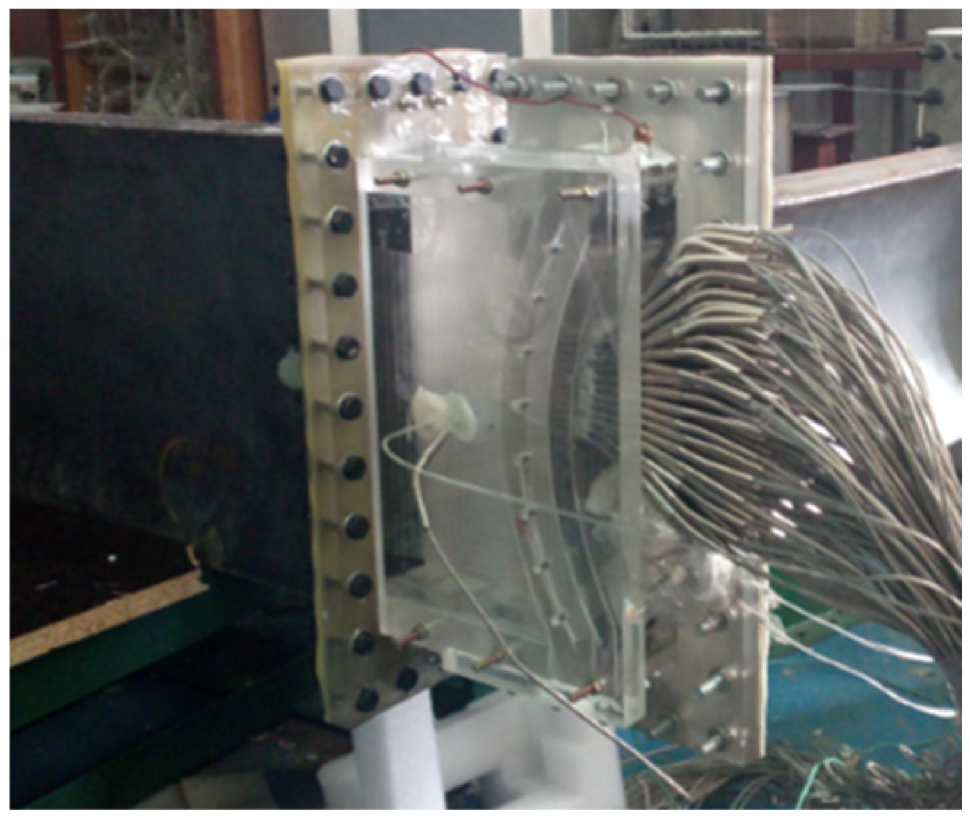
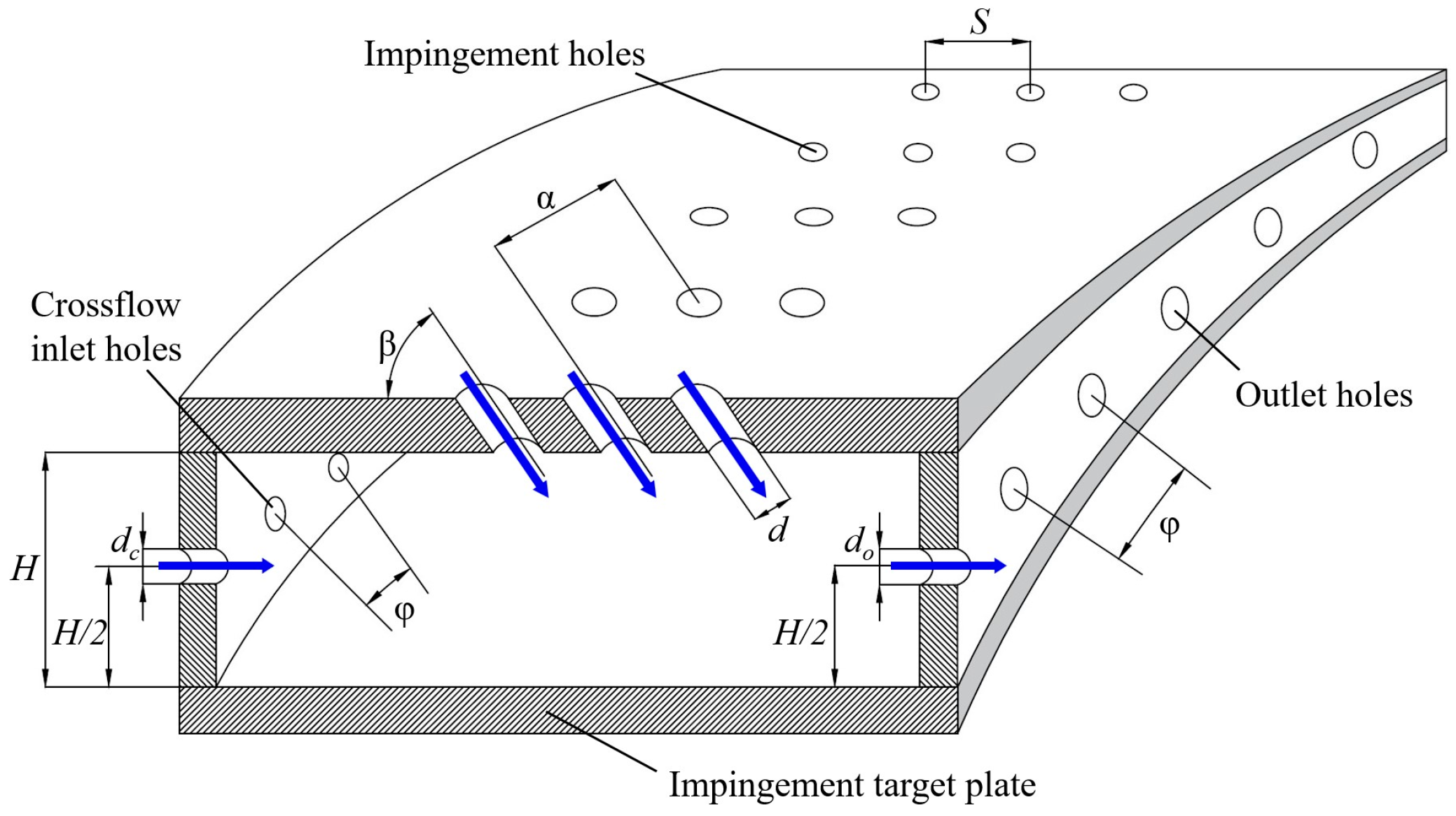
2. Experimental Setup and Test Facility

Test System

The test system is mainly composed of mainstream pipelines and crossflow pipelines, as shown in Figure 1. A 5 m3/min screw compressor provides air flow to the mainstream pipeline and the crossflow pipeline. A mass flow controller (measuring range 1000 L/min, accuracy level Ⅰ) is installed on the mainstream pipeline to measure the mass flow of the mainstream, and a mass controller (measuring range 200 L/min, accuracy level Ⅰ) is installed on the crossflow pipeline to measure the mass flow of the crossflow. K-type thermocouples are used to measure the mainstream temperature, and a PSI9116 pressure scanner (TE Connectivity Ltd., Berwyn, PA, USA) is used to measure the mainstream pressure at the inlet of the test section. The tip of the thermocouples and pressure measurement port are located at the core flow of the mainstream.
The structure of the turbine casing is periodic, so the test research is conducted on 1/6 of the entire ring. The test section is made of rubber wood with low thermal conductivity, as shown in Figure 2. The mainstream enters from the top of the impingement hole, and the crossflow enters from the side of the impingement chamber. The mainstream and the crossflow converge in the narrow impingement chamber and then flow out through the outlet hole on the side wall of the impingement chamber. The curved impingement target plate is 20 mm thick. A layer of heating film with a thickness of 0.02 mm is affixed to the surface of the target plate to provide uniform heat flux. The temperature of the heating film is measured by 300 K-type thermocouples with a diameter of 1 mm uniformly arranged on the target plate, and the streamwise and spanwise spacing thermocouples are shown in Figure 3 and Figure 4, respectively. In order to ensure the accuracy and reliability of the thermocouple measurement results, the thermocouples are mounted in the mounting holes, the bottom of which are located exactly at the inner wall of the impingement chamber. Additionally, the mounting holes are filled with thermal silica gel with high thermal conductivity to reduce contact thermal resistance. All the thermocouples are connected to a multi-channel temperature tester. The sampling frequency of the temperature tester is 10 Hz, and the resolution is 0.1 °C. Figure 5 shows a photo of the test section.
Figure 6 shows the geometry of the impingement cooling structure, where H is the impingement distance, α is the circumferential spacing angle of the impingement hole, and β is the impingement direction angle of the impingement hole. The diameter of the impingement hole is d, the diameter of the crossflow inlet hole is dc, and the diameter of the outlet hole is do.
In the test section, the diameter of impingement hole d is 2 mm, the diameters of the crossflow inlet hole dc and the outlet hole do are both 3 mm, and the circumferential angle φ is 15°. The relative impingement distance H/d are 3, 6, and 9, respectively. The impingement angles β are 45°, 75°, and 90°, respectively. Detailed geometric parameters are shown in Table 1.
During the test, after monitoring the stability of the mainstream inlet pressure, the wall temperature of the heating film is measured when it is not powered on and when it is powered on. The acquired temperature measurement data are then processed by algorithm to calculate the convective heat transfer coefficient and the Nusselt number. Ultimately the Nusselt number contour is obtained with Tecplot 2014.

3. Definition of Parameters

In this study, the single hole impingement Reynolds number is not guaranteed to be consistent. Therefore, the equivalent impingement Reynolds number Rej can be defined with the equivalent mass flow through the target surface m, the arc length l of the periodic target plate which is selected as the characteristic length. Additionally, A0 is the area of the target plate and μ is dynamic viscosity of the airflow.
R e j = m l A 0 μ
The heat Q of the heating film comes from the Joule effect generated by the current and voltage provided by the DC power supply, which is defined as follows:
Q = U I
U is the voltage value at the ends of the heating film. I is the current flowing through the heating film.
The material used for the test facility is not strictly thermal insulation material, so there will be heat loss, Qloss, caused by heat conduction from the wall of the impingement target plate during the experiment, which is defined as follows:
Q l o s s = A λ T w T o u t s i d e δ
where Tw is the temperature of the heating film, Toutside is the temperature of the outer wall of the target plate and λ is the thermal conductivity of the target plate. In this test, the target plate is made of plexiglass, and λ is constant 0.18 w/(m·k). δ is the thickness of the target plate and A is the heating area.
Excluding the heat loss due to heat conduction, the convective heat transfer coefficient is defined as follows:
h = Q Q l o s s A T w T 0
T0 is the wall temperature when the heating film is not powered on.
The Nusselt number Nu is defined as follows:
N u = h l λ a i r
λair is the thermal conductivity of the airflow.
In order to analyze of the impact of the number of impingement holes on impingement heat transfer, the hole consistency Is is defined as follows:
I s = 360 ° α
α is the circumferential angle between two adjacent impingement holes.

4. Analysis of Test Results

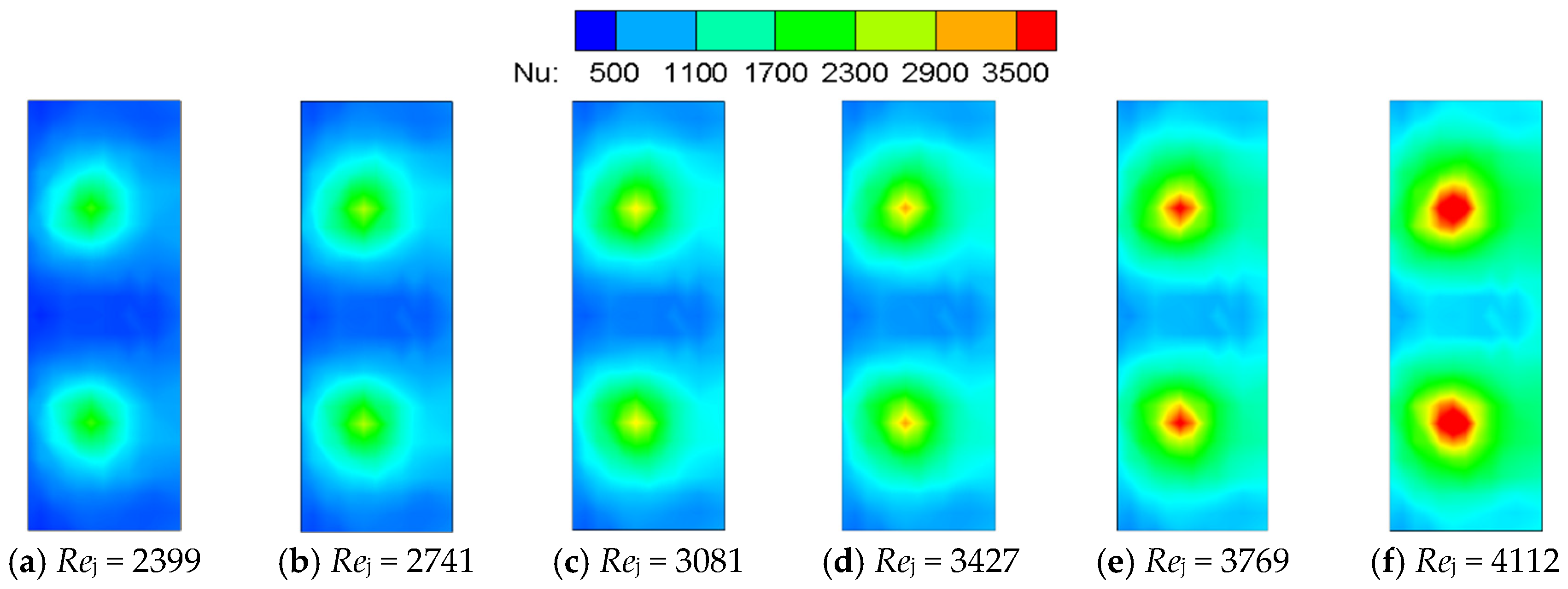
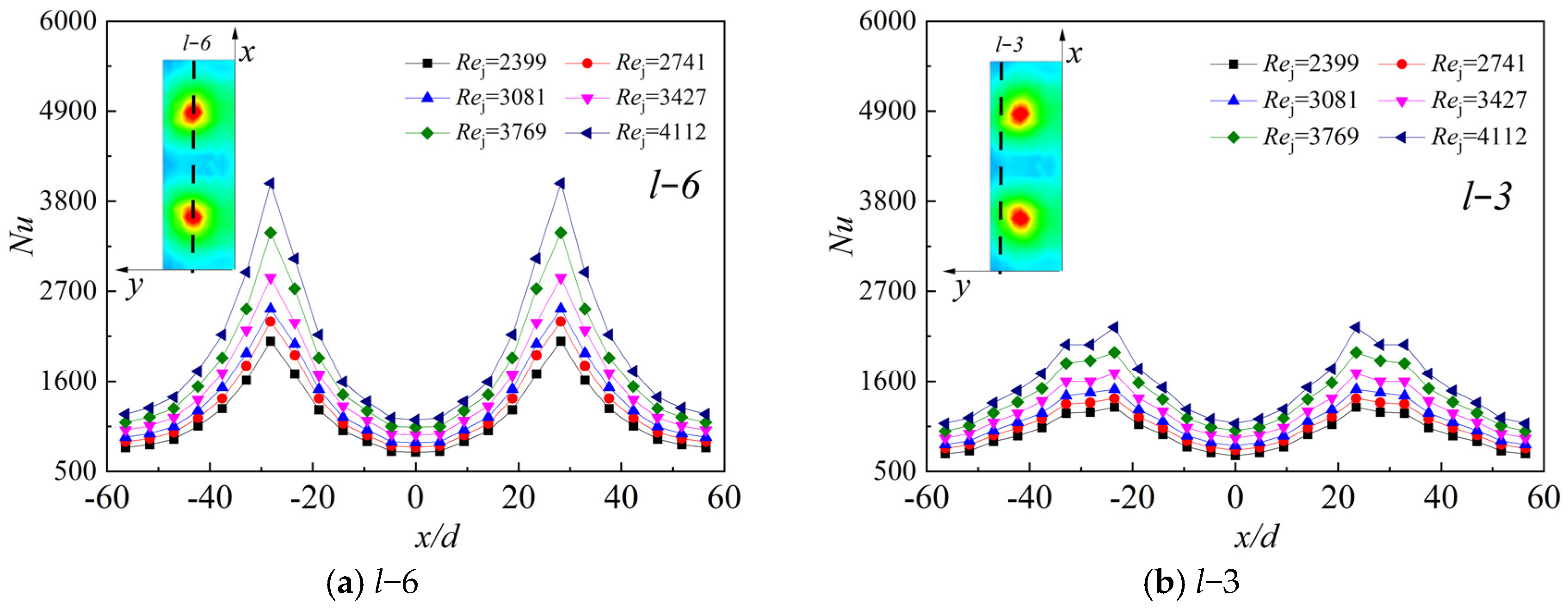
4.1. The Effect of Rej on Nu in Typical Structure

Figure 7 shows the Nu contours of six different Rej—2399, 2741, 3081, 3427, 3769 and 4112—with the relative impingement distance H/d = 6, the circumferential impingement hole spacing (consistency) Is = 24, impingement angle β = 90°, and with the test conducted without initial crossflow. There is a strong circular heat transfer zone on the target plate with the effect of impinging jets. With the increase of Rej, Nu also gradually increases at the impingement stagnation point, and the coverage area of the jets also gradually expands.
Figure 8 shows the Nu distribution on two characteristic lines (across the center of the impingement stagnation point in the X-axis direction). The peak corresponds to the impingement stagnation point and the valley corresponds to the area between two adjacent impinging jets.
Figure 8a,b show that, as the impingement Rej increases, the local Nu on the target plate also increases. There are two obvious peaks at the positions of r−8 and r−18. These two peaks are the impingement stagnation areas of the jets. On the one hand, the velocity boundary layer and the temperature boundary layer of the impingement stagnation zone are thin and not fully developed. On the other hand, the core area of the jets carries high-momentum fluid where the disturbance of the fluid is intense, which enhances the heat transfer in the stagnation area. The flowing direction of the airflow changes because of the blocking of the target plate when the impinging jet hits its surface. Therefore, the jet, redirected around the stagnation center, where intensity gradually decreases, leads to a weaker heat transfer. Thus, the change of Nu from peak to valley on the curve can be observed in the figure.
In addition, Figure 8a,b show the local Nu contours at l−3 and l−6, with the same structure and test conditions. Comparing the two lines, there is a large difference between the peak and valley at l−6, and l−3 is relatively flat. As it deviates from the impingement stagnation point, the influence of the impinging jets at l−3 becomes weak and the jets cannot impact directly. Additionally, the heat transfer becomes worse and the maximum value of the curve decreases. The heat transfer difference at the valley is not as clear as those at the peak.

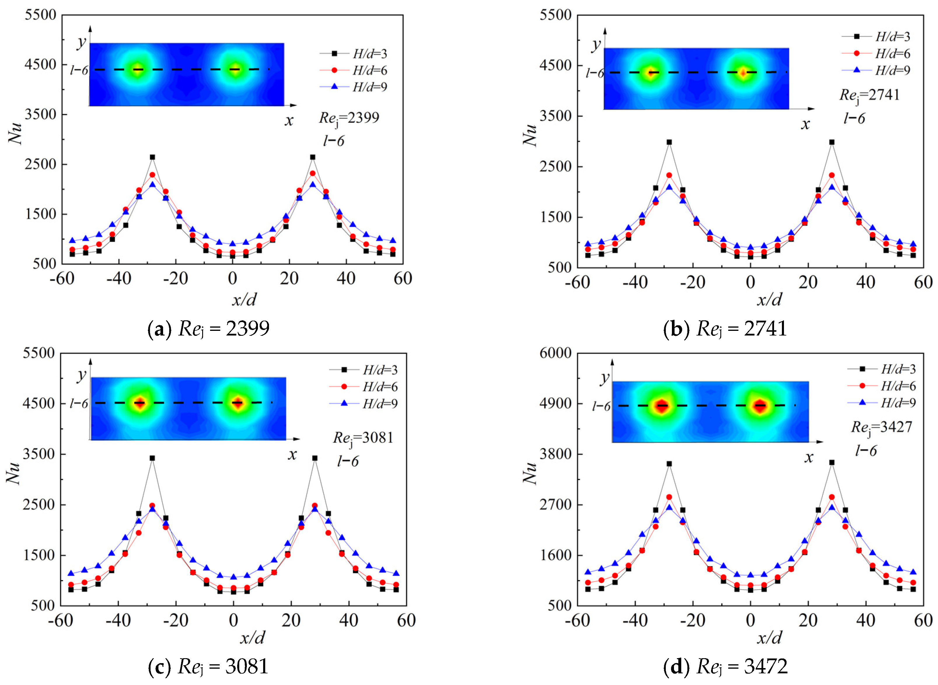
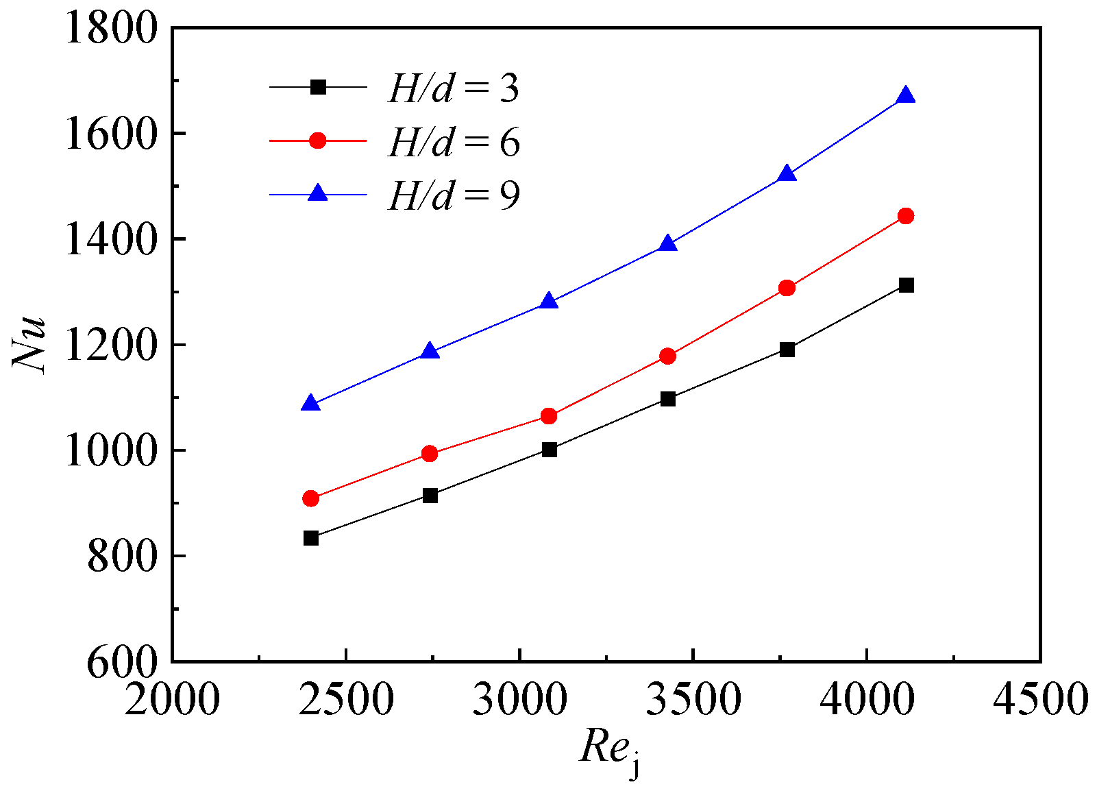
4.2. Effect of Relative Impingement Distance H/d on Nu

Figure 9 shows the Nu contour on the target plate under Rej = 2399 and three different relative impingement distance (H/d), the circumferential impingement hole spacing (consistency) Is = 24, impingement angle β = 90°, and the test is conducted without initial crossflow. Clearly, the overall Nu distribution is similar but with different H/d. The impinging zone becomes an obvious circular area, prominently spreading from the stagnation point. With the increase of H/d, the heat transfer coefficient in the impinging zone gradually decreases. Comparing contours reveals that the heat transfer coefficient reaches its peak at the impingement stagnation point when H/d is 3. Additionally, the heat transfer performance will be more uniform with the increase of H/d. This is because when H/d is at a low range, the impinging jet directly impacts the plate, which contributes to strong convective heat transfer at the impingement stagnation point. However, the secondary jet zone formed by the jets impinging on the target plate is clamped by the up and low walls in the lower impingement cavity and with the action of airflow viscosity, the kinetic energy of impinging airflow decreases rapidly, which reduces the coverage area of the impinging secondary jet zone. Therefore, the temperature difference on the target plate is obvious. The increase of H/d adds to the time the jet takes to reach the wall. However, the kinetic energy loss between the secondary jet zone and the upper and lower walls is reduced, which allows the impinging airflow to cover more area, and thus leads the temperature distribution on the target plate to become more uniform.
The local Nu comparison at l−6 under three different H/d is shown in Figure 10, where the circumferential impingement hole spacing (consistency) Is = 24, impingement angle β = 90°, and Rej changes from 2399 to 4112. It can be clearly seen in Figure 10 that the peak position corresponds to the local Nu of the impingement stagnation point, and that the valley position is the area in which the two adjacent impinging jets take less effect. Clearly the local Nu is larger when the impingement distance gets smaller near r−8 and r−18. However, in other areas, the greater the relative impingement distance the greater the local heat transfer coefficient. This is because, in the impingement cavity, with a smaller relative impingement distance and a lower height of the impingement cavity, the rolled-up jet will impact the upper surface faster. The energy of airflow quickly dissipates due to the viscosity of the airflow, which causes that the boundary layer to become thicker and the heat transfer effect to become reduced. Therefore, the local heat transfer coefficient instead increases as the impingement distance increases near r−3.
Figure 11 shows the variation of the average Nu on the target plate with different Rej and three kinds of relative impingement distances. It can be seen from the curves that the average Nu of the plate increases with the increase of Rej. However, the heat transfer is the best with the same Rej when the relative impingement distance H/d = 9.

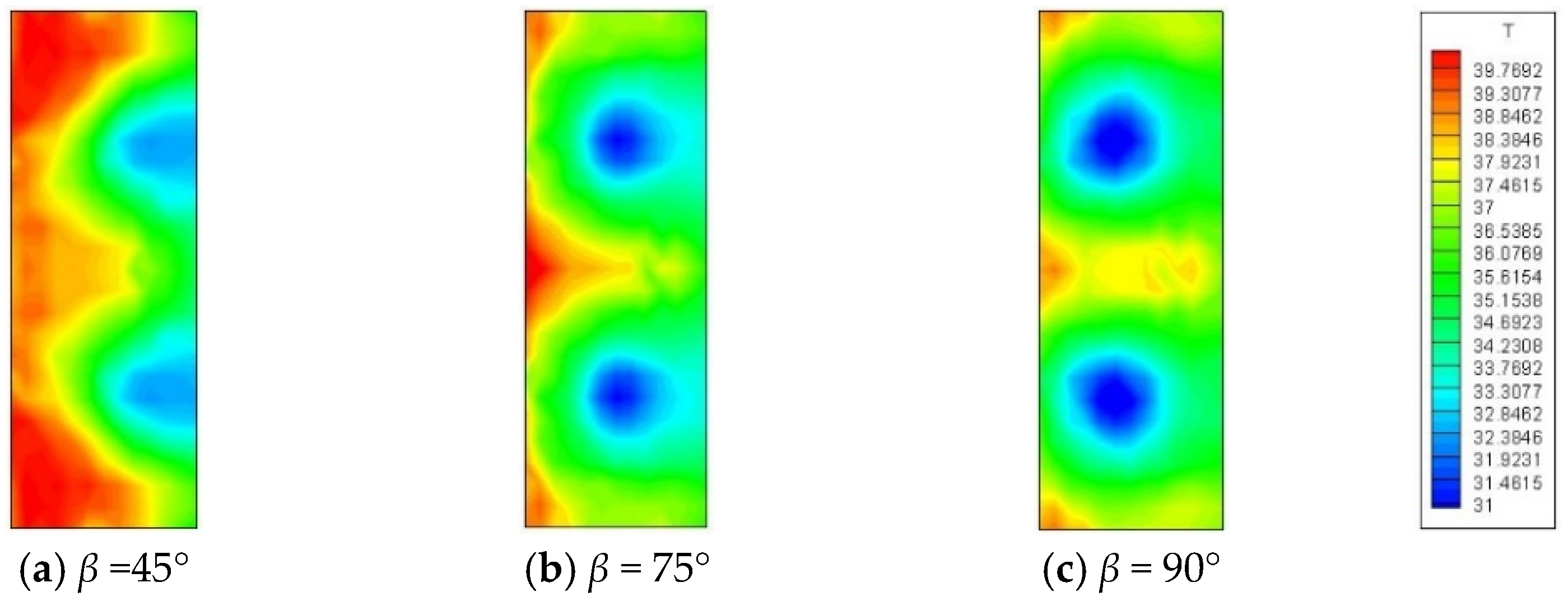
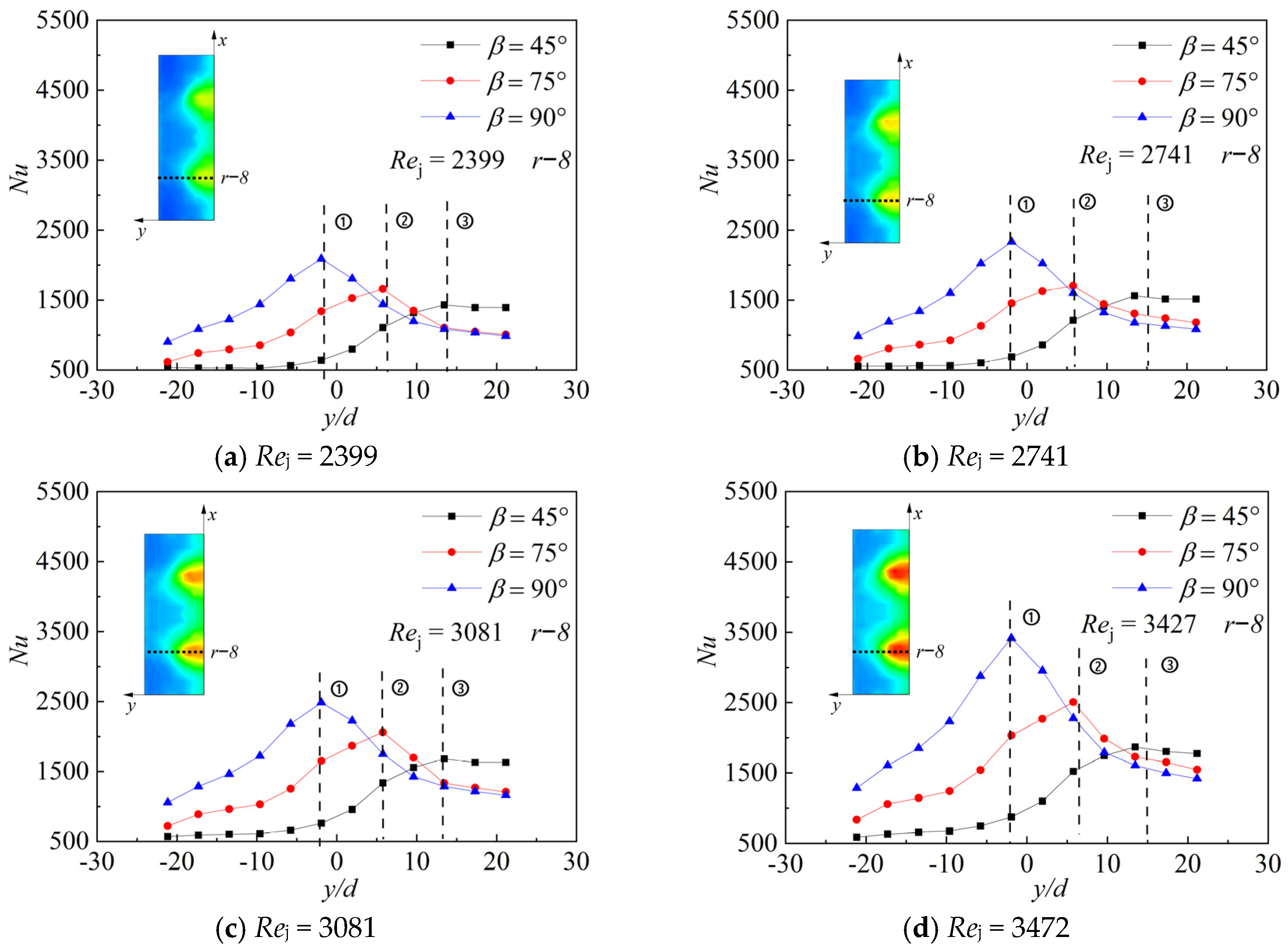
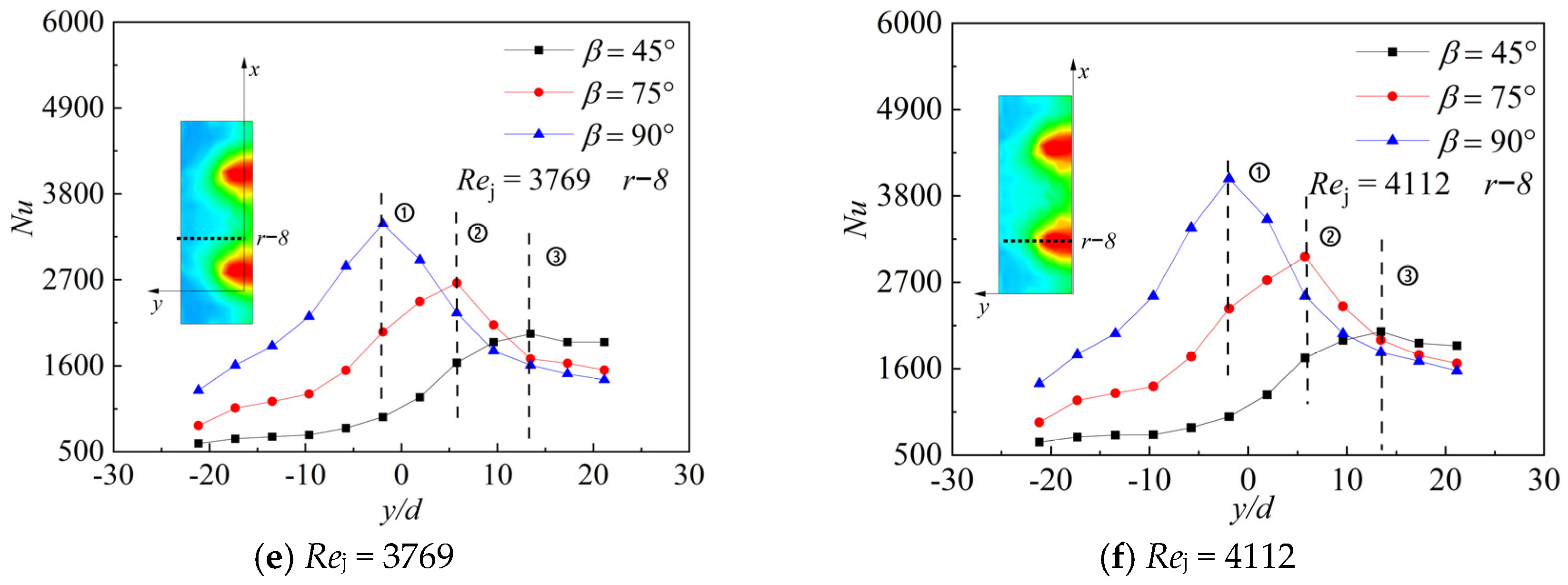
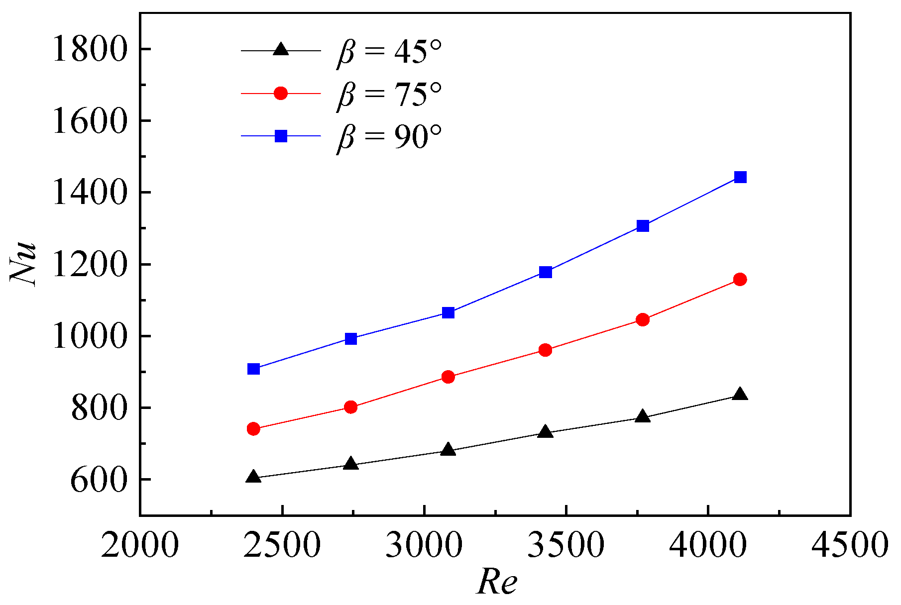
4.3. Effect of Impinging Angle (β) on Nu

Figure 12 shows the temperature contours obtained from the tests of the target plate with three different impinging angles (β = 45°, 75° and 90°). At each impingement angle there is clearly a circular low temperature zone forming on the plate that is impacted with jets. However, with the bigger impingement angle, the low temperature zone formed by the jets’ impingement gradually becomes larger, the direct impingement zone also moves from the sidewall to l−6 and the center temperature of the impingement stagnation zone also gradually decreases. The high temperature zone gradually decreases and almost disappears.
When the impingement angle β = 45°, the distance between the jets and the plate with the same relative impingement distance is longer than those when the impingement angle β is 75° or 90°. Therefore, the time required for the jet to reach and impact the plate will be longer when the impingement angle β = 45°. Because the impinging jets will expand in a circular shape and the strength of the core jet zone reaching the plate will also reduce, there is a further reduction in the heat transfer effect. The impinging jets will not spread around on the target plate as a direct impingement because the impinging occurs at an oblique angle. Instead, it will have a tendency to flow along the target plate in a certain direction, which weakens the effect of heat transfer before the airflow impacts the sidewall. Therefore, the left zone of l−6 displays a high temperature zone which is almost unaffected by the impingement when the impingement angle β = 45°. Only the impingement stagnation zone shows a semi-elliptical low temperature zone when the impingement angle β = 45°. Additionally, the temperature of the low temperature zone is higher when the impingement angle β = 45° than it is when the angle is 75° or 90°.
Figure 13 shows the local Nu variation on r−8 at three impingement angles β = 45°, 75°, and 90° with six different Rej. Three curves still have peaks in the Y-axis direction of the wall in the curves at ①, ②, ③. r−8 passes through the peak position of the impingement stagnation zone, so each peak on the impingement angle β curve corresponds with the different stagnation point positions shown in the temperature contour. As the impingement angle decreases, the impact position moves in the positive direction of the Y-axis. However, we should also note that, as the stagnation point moves to the right, the peak value gradually decreases, which shows that the heat transfer effect at the stagnation point is reducing.
Figure 14 shows the comparison of the average Nu on the target plate with different impingement angles β. With the same impingement angle and other geometric parameters, the average Nu on the target plate increases with the increase of Rej. However, it is also notable that, with the same Rej, the impingement angle β = 90° is larger than β = 75° and 45°, so the heat transfer effect will be improved when the impinging jet impacts the target plate vertically through an impingement hole which is vertical to the target plate.

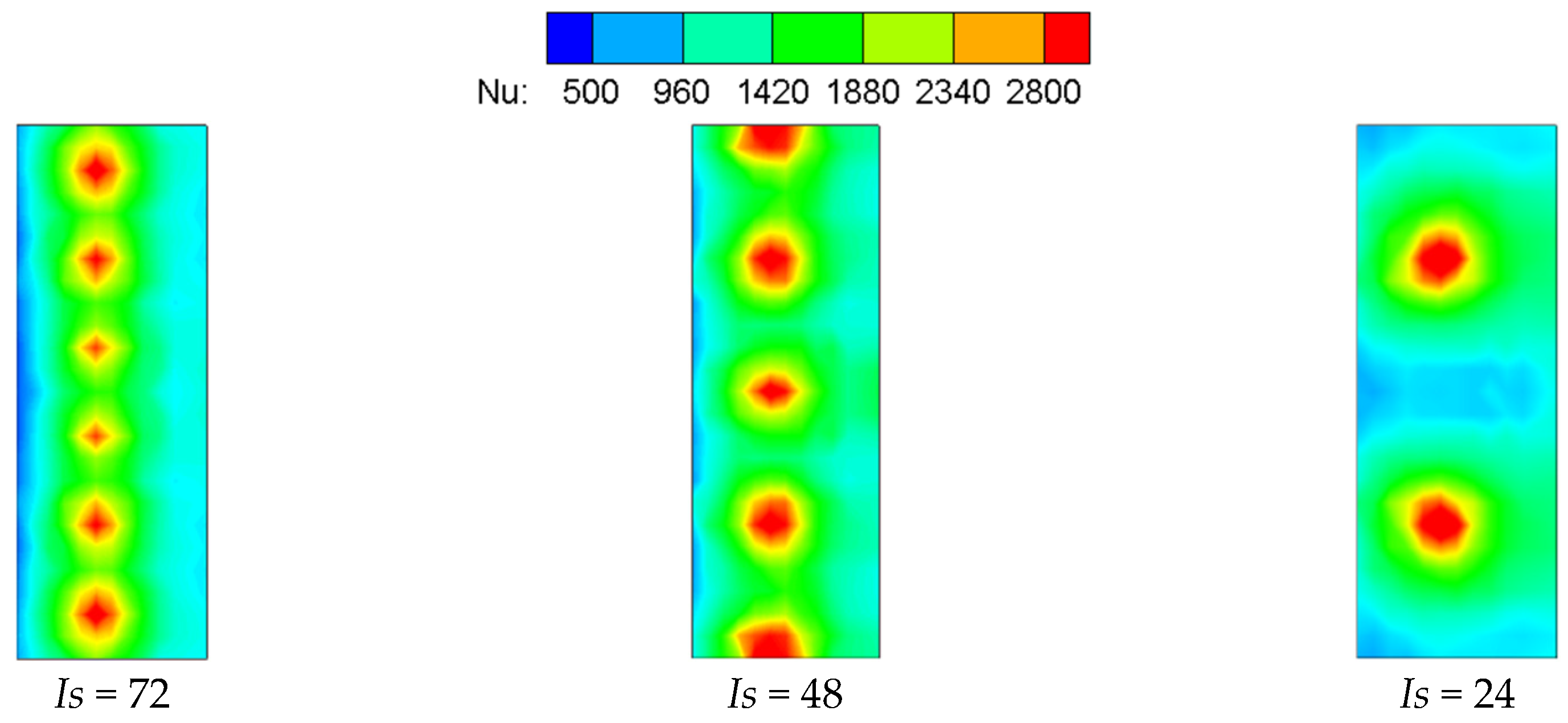
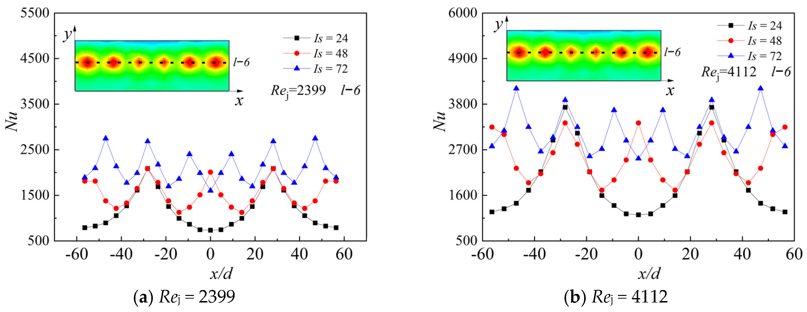
4.4. The Effect of Consistency (Is) on Nu

Figure 15 shows the Nu contours of the target plate with three different circumferential impingement angles (consistency) and the same impingement Rej (Rej = 4112). With the increase of consistency, there are more jet beams on the same arc target area, so it can be clearly seen from the contour that the greater the consistency, the stronger the heat transfer zone formed by the jet beams.
From the comparison, with the increase of the consistency of the impingement holes, the covering effect of the airflow formed by the impinging jets on the target plate is better and the temperature gradient on the target plate is smaller. This is when the number of impingement holes decreases and the adherence jets in the near wall region rapidly roll up, which dissipates the kinetic energy due to viscous friction. As a result, limited film is developed, so that it becomes difficult to cover the area between the two adjacent impinging jets with the film. The results show that, when the consistency of the impingement holes is at a low range, the heat transfer uniformity of the target plate is worse than that of the higher consistency. This indicates that there is a large temperature gradient on the impact target when the consistency is low.
Figure 16 shows the distribution curve of Nu at l−6 for the three circumferential impingement spacing angles (impingement hole consistency) when the Rej = 2399 and 4112. The higher consistency, the more peaks appear on the corresponding curve. A higher consistency means more impingement holes and more impingement stagnation points formed on the target plate, which results in stronger heat transfer zones. However, the smaller consistency, the smaller is the number of valleys on the curve. It can be seen from the gap between the peaks and valleys on the curve that the consistency Is = 72 is smaller than that when the consistency Is = 48. When the consistency Is = 72, the peak–valley gap is at its largest. This is because the higher the consistency, the smaller the distance between two adjacent impinging jets and the higher is the mixing intensity of the impinging jets.
With the same mass flow, the higher the consistency, the larger the number of holes and the smaller Rej in the holes. However, the overall temperature gradient distribution of the target plate appears to be relatively uniform because of denser hole spacing, which leads to an enhanced heat transfer effect of the region between two jets. Additionally, it can be seen from the figure that, when the consistency Is = 72, the maximum Nu at the stagnation point is also related to the strengthening of the mixing between two adjacent jets.
Figure 17 shows the curves of the average Nu of the target plate with Rej in the three consistency conditions. Generally, the surface average Nu increases with the increase of Rej and the surface average Nu is the largest when consistency Is = 72. Under the consistent mass flow of the mainstream, Nu is weakened due to the decrease of single-hole Rej. However, a larger consistency leads to more impingement holes. A large consistency means a large number of holes, which improves the flow mixing between two adjacent jets and enhances the heat transfer between the jets and the target plate. The latter has a greater advantage, indicating that, when the mass flow of the mainstream does not change, the increase in the consistency of the impingement hole improves the surface heat transfer.

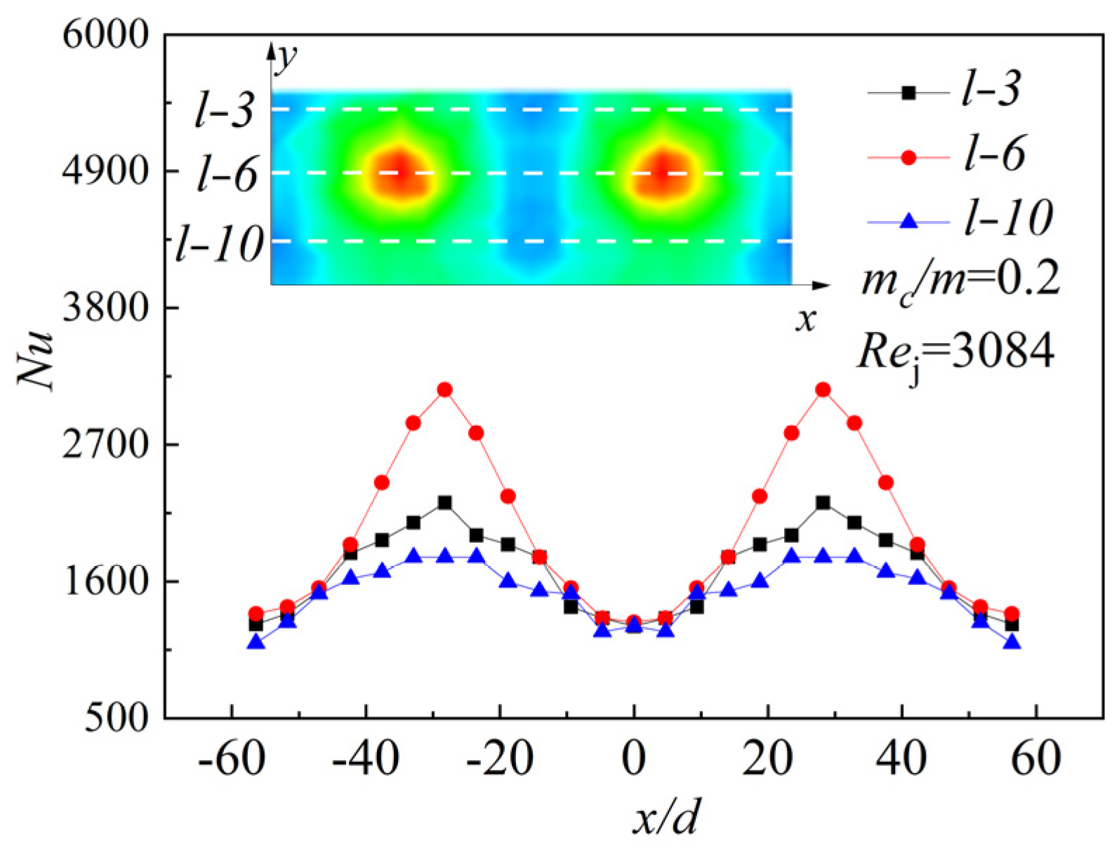
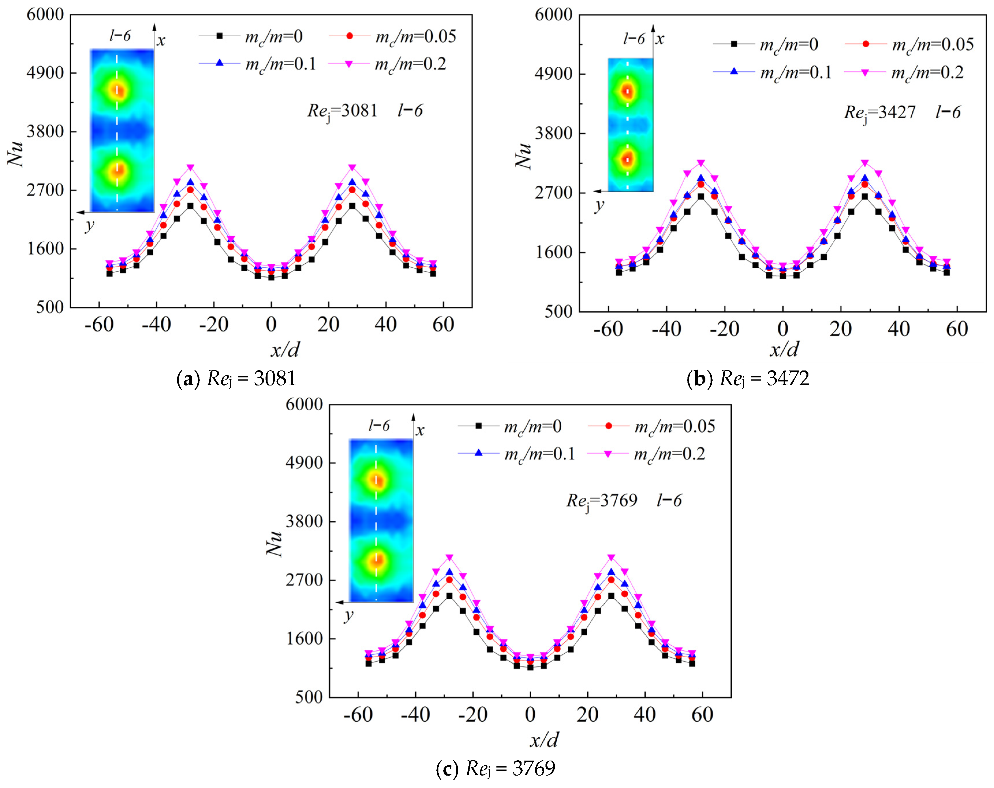
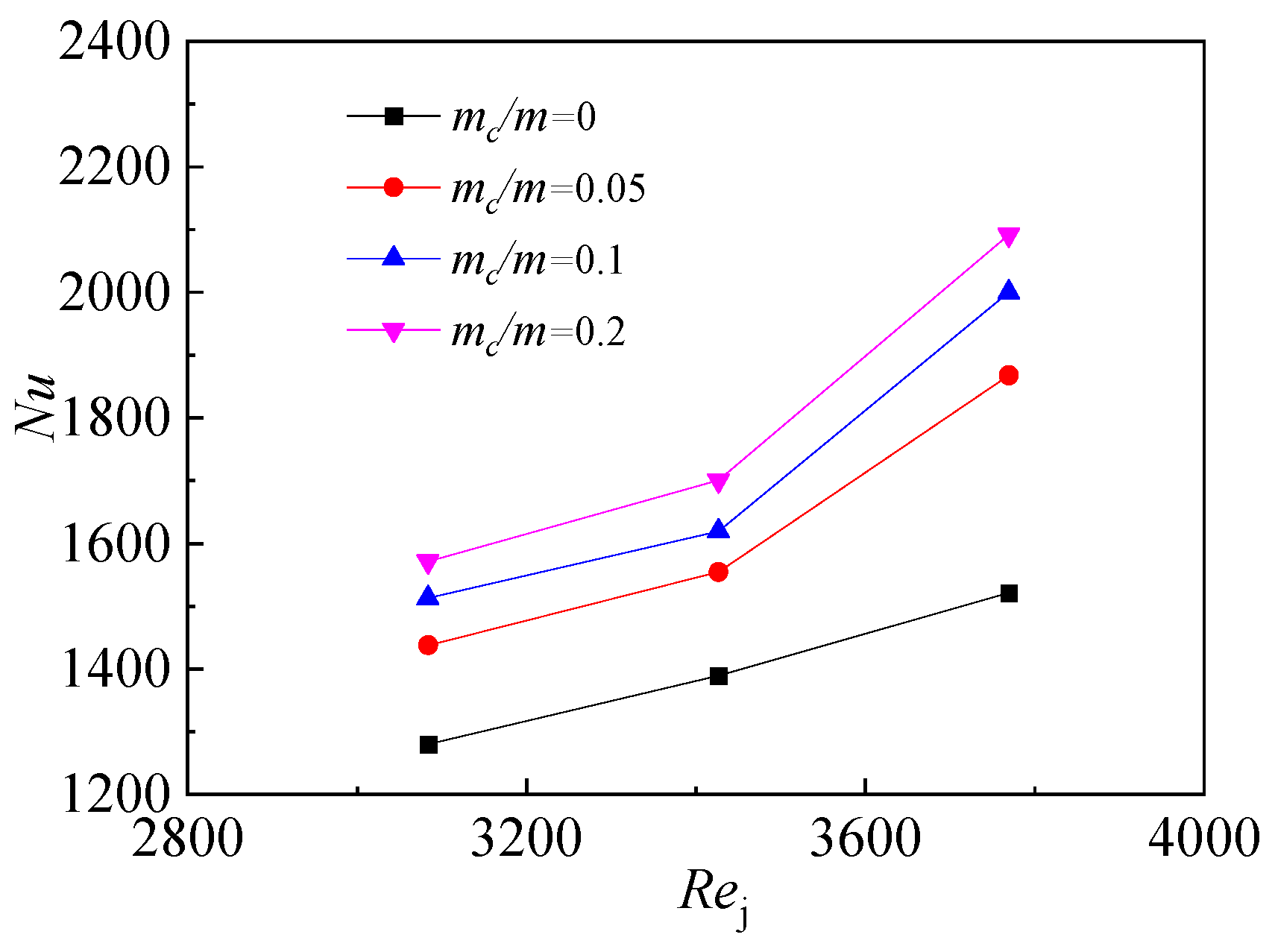
4.5. The Effect of Initial Crossflow Ratio (mc/m) on Nu

Figure 18 shows the test results with the relative impingement distance H/d = 9, the hole consistency Is = 24, and the impingement angle β = 90°. The Nu contours on the target plate with any mainstream Rej are consistent and the Nu contour showing the effect of the initial crossflow when Rej = 2399 is displayed as an example. It can be seen from Figure 18 that, with the increase of the crossflow ratio under the same Rej, the Nu at the impingement stagnation point gradually increases, and the overall heat transfer effect on the target plate is gradually improved. Additionally, with a large crossflow ratio, the heat transfer of the impinging jets on the plate is better than that with a small crossflow ratio. The analysis shows that, with the action of the crossflow, the secondary flow of impinging jets will be dispersed by the crossflow. In the mixing process of the crossflow and the impinging secondary flow, crossflow also plays the role of blowing off the boundary layer formed by the impinging jets on the target plate, increasing the heat transfer between the fluid and the solid surface, which achieves the purpose of cooling the wall. Additionally, with the increase of the mass flow of the crossflow, the mass flow of air flow in the impingement cavity also objectively increases, which in turn improves the heat transfer in the cavity.
Figure 19 shows l−3, l−6 and l−10 of Nu distribution with the initial crossflow ratio mc/m = 0.2. l−6 passes through the stagnation point, so the heat transfer effect at the stagnation point position is better and the peak value is higher on the curve. However, it is worth noting that, in Figure 19, the position of l−3 and l−10 are characteristic curves with the same distance from l−6. The overall Nu level of l−10 is lower than that of l−3, because the position of l−3 is closer to the initial crossflow inlet. Additionally, it can be seen that the crossflow enhances the heat transfer on the plate.
Figure 20 shows the local Nu at l−6 when initial crossflow mc/m = 0, 0.05, 0.1, 0.2 with different Rej. As the initial crossflow ratio increases, its local Nu also increases, which is consistent with the conclusions of previous analyses. Figure 21 shows the average Nu on the target plate, with the effect of different mainstream Rej and different crossflow ratios. Finally, as the initial crossflow ratio increases, the average Nu is gradually increasing.

5. Conclusions

(1)
Effect of the equivalent Reynolds number: The effectiveness of heat transfer on the impingement plate enhances with an increase in the Reynolds number (Rej). Specifically, the peak heat transfer efficiency occurs at a Rej of 4112, showcasing significant improvements in local and average heat transfer performance.
(2)
Effect of elative impingement distance: The distance between the jet and the target plate plays a crucial role in heat transfer efficiency. For a shorter distance (H/d = 3), we observe a peak in local heat transfer rates, whereas, for a larger distance (H/d = 9), the average heat transfer rate is more favorable, especially at an Rej of 4112.
(3)
Effect of impingement angle: Changing the angle at which the jet hits the target surface affects heat transfer, with a 90° angle offering the most significant benefits. This configuration achieves the highest local and average heat transfer rates across all tested Reynolds numbers, peaking at a Rej of 4112.
(4)
Effect of hole consistency: Increasing the number of holes around the circumference of the impingement jet enhances the uniformity of the jet’s coverage and, consequently, the overall heat transfer efficiency. The best performance is noted with the highest consistency level (Is = 72) at all Reynolds numbers, showing a peak in both local and average heat transfer at an Rej of 4112.
(5)
Effect of initial crossflow: Introducing a crossflow at the inlet significantly benefits the heat transfer by enhancing the removal of boundary layers near the plate’s surface. As the ratio of initial crossflow increases, so does the heat transfer effectiveness, with the most notable improvements observed at an Rej of 3769, with an initial crossflow ratio of 0.2.
In summary, heat transfer efficiency is positively influenced by higher flow velocity, optimal impingement distances and angles, increased consistency of impingement holes, and the introduction of an initial crossflow. By adjusting these factors, one can significantly enhance the convective heat transfer of the target plate.

Author Contributions

Conceptualization, F.Z.; data curation, Z.C.; formal analysis, R.S.; investigation, Z.C.; methodology, F.Z.; project administration, W.Y.; resources, W.Y.; software, Y.L.; supervision, W.Y.; validation, R.S.; writing—original draft, Z.C.; writing—review and editing, Y.L. All authors have read and agreed to the published version of the manuscript.

Funding

This research received no external funding.

Data Availability Statement

Data are contained within the article.

Conflicts of Interest

The authors declare no conflict of interest.

Nomenclature

AHeating area
A0Area of the target plate
dcDiameter of impingement hole
dDiameter of crossflow inlet hole
doDiameter of crossflow outlet hole
HImpingement distance
H/dRelative impingement distance
hConvective heat transfer coefficient
ICurrent flowing through the heating film
IsImpingement hole consistency
lArc length of the periodic target plate
mEquivalent mass flow through the target surface
mcMass flow of the crossflow
mc/mInitial crossflow ratio
NuNusselt number
QHeat generated by heating film
QlossHeat loss due to conduction
RejImpingement Reynolds number
T0Wall temperature when the heating film is not powered on
TwTemperature of the heating film
ToutsideTemperature of the outer wall of the impingement target plate
UVoltage value at the ends of the heating film
Greek alphabets
αCircumferential spacing angle of the impingement hole
βImpingement direction angle of the impingement hole
δThickness of the target plate
λThermal conductivity of the impingement target plate
λairThermal conductivity of the airflow
μDynamic viscosity of the mainstream
φCircumferential spacing angle of the crossflow inlet and outlet hole

References

  1. Yang, J.; Wang, X.J.; Yang, Q. Advances in jet impinging heat transfer. Vacuum Cryog. 2018, 24, 217–222. [Google Scholar]
  2. Xie, G.; Liu, C.L.; Ye, L.; Wang, R.; Niu, J.J.; Zhai, Y.N. Effects of impingement gap and hole arrangement on overall cooling effectiveness for impingement/effusion cooling. Int. J. Heat Mass Transf. 2020, 152, 119449. [Google Scholar] [CrossRef]
  3. Tepe, A.Ü.; Yetişken, Y.; Uysal, Ü.; Arslan, K. Experimental and numerical investigation of jet impingement cooling using extended jet holes. Int. J. Heat Mass Transf. 2020, 158, 119945. [Google Scholar] [CrossRef]
  4. Metzger, D.E.; Florschuetz, L.W.; Takeuchi, D.I.; Behee, R.D.; Berry, R.A. Heat transfer characteristics for inline and staggered arrays of circular jets with crossflow of spent air. J. Heat Transf. 1979, 101, 526–531. [Google Scholar] [CrossRef]
  5. Florschuetz, L.W.; Metzger, D.E.; Su, C.C. Heat Transfer Characteristics for Jet Array Impingement with Initial Crossflow. In Proceedings of the ASME 1983 International Gas Turbine Conference and Exhibit, Phoenix, AZ, USA, 27–31 March 1983. [Google Scholar]
  6. Florschuetz, L.W.; Su, C.C. Effects of Crossflow Temperature on Heat Transfer Within an Array of Impinging Jets. J. Heat Transf. 1987, 109, 74–82. [Google Scholar] [CrossRef]
  7. Zhang, Z.Y.; Zhang, J.Z.; Yang, W.H. Convective heat transfer of jet impingement inside semi-confined channel. J. Aeronaut. Power 2006, 4, 626–630. [Google Scholar]
  8. León De Paz, M.; Jubran, B.A. Numerical modeling of multi micro jet impingement cooling of a three-dimensional turbine vane. Heat Mass Transf. 2011, 47, 1561–1579. [Google Scholar] [CrossRef]
  9. Attalla, M.; Salem, M. Experimental Investigation of Heat Transfer for a Jet Impinging Obliquely on a Flat Surface. Exp. Heat Transf. 2014, 28, 378–391. [Google Scholar] [CrossRef]
  10. Wang, K.; Li, H.; Zhu, J. Experimental study of heat transfer characteristic on jet impingement cooling with film extraction flow. Appl. Therm. Eng. 2014, 70, 620–629. [Google Scholar] [CrossRef]
  11. Wang, L.; Zhang, J.Z.; Yang, W.H. Experimental research on heat transfer characteristics of denser jet array impingement. Hangkong Dongli Xuebao/J. Aerosp. Power 2009, 24, 1264–1269. [Google Scholar]
  12. Shin, M.; Senguttuvan, S.; Kim, S. Investigations of Flow and Heat Transfer Characteristics in a Channel Impingement Cooling Configuration with a Single Row of Water Jets. Energies 2021, 14, 4327. [Google Scholar] [CrossRef]
  13. Otero Perez, J.J.; Sandberg, R.D.; Mizukami, S.; Tanimoto, K. High-fidelity simulations of multi-jet impingement cooling flows. J. Turbomach. 2021, 143, 081011. [Google Scholar] [CrossRef]
  14. Forster, M.; Weigand, B. Experimental and numerical investigation of jet impingement cooling onto a concave leading edge of a generic gas turbine blade. Int. J. Therm. Sci. 2021, 164, 106862. [Google Scholar] [CrossRef]
  15. Mao, J.K.; Miao, G.J.; Liu, Z.X. Experimental study of the flow structures of the concave surface with inclined impingement in limited space. J. Aeronaut. Power 2010, 25, 11–17. [Google Scholar]
  16. Waehayee, M.; Tekasakul, P.; Eiamsaard, S.; Nuntadusit, C. Flow and Heat Transfer Characteristics of in-Line Impinging Jets With Crossflow At Short Jet-To-Plate Distance. Exp. Heat Transf. 2015, 28, 511–530. [Google Scholar] [CrossRef]
  17. Lu, Q.; Muthukumar, R.; Ge, H.; Parameswaran, S. Numerical study of a rotating liquid jet impingement cooling system. Int. J. Heat Mass Transf. 2020, 163, 120. [Google Scholar] [CrossRef]
  18. Qiu, D.; Luo, L.; Zhao, Z.; Wang, S.; Wang, Z.; Sunden, B. On heat transfer and flow characteristics of jets impingement on a concave surface with varying pin-fin arrangements. Int. J. Therm. Sci. 2021, 170, 107163. [Google Scholar] [CrossRef]
  19. He, W.; Deng, Q.; Yang, G.; Feng, Z. Effects of Turning Angle and Turning Internal Radius on Channel Impingement Cooling for a Novel Internal Cooling Structure. J. Turbomach. 2021, 143, 091005. [Google Scholar] [CrossRef]
  20. Ahmed, F.B.; Tucholke, R.; Weigand, B.; Meier, K. Numerical Investigation of Heat Transfer and Pressure Drop Characteristics for Different Hole Geometries of a Turbine Case Impingement Cooling System. In Proceedings of the ASME Turbo Expo: Turbine Technical Conference and Exposition, Vancouver, BC, Canada, 6–10 June 2011. [Google Scholar]
  21. Ma, L. Study on the Impact Heat Transfer Characteristics of Internal Array of Turbines. Master’s Thesis, Nanjing University of Aeronautics and Astronautics, Nanjing, China, 2014. [Google Scholar]
  22. Ortega-Casanova, J.; Granados-Ortiz, F.J. Numerical simulation of the heat transfer from a heated plate with surface variations to an impinging jet. Int. J. Heat Mass Transf. 2014, 76, 128–143. [Google Scholar] [CrossRef]
  23. Jia, Y.; Long, P.; Xueqin, B.; Shen, X.; Lin, G.; Bai, L. Experimental investigation and correlation development of jet impingement heat transfer with two rows of aligned jet holes on an internal surface of a wing leading edge. Chin. J. Aeronaut. 2018, 31, 1962–1972. [Google Scholar]
  24. Yamagami, S. Surface Orientation Effect on Local Heat Transfer by Round Water Jet Impingement. Flow Turbul. Combust. 2019, 102, 485–496. [Google Scholar] [CrossRef]
  25. Sriromreun, P.; Sriromreun, P. A Numerical and Experimental Investigation of Dimple Effects on Heat Transfer Enhancement with Impinging Jets. Energies 2019, 12, 813. [Google Scholar] [CrossRef]
  26. Yan, J.K.; Guo, T.; Zhu, H.R.; Zheng, J.; Guo, W.; Su, Y.L. Experimental investigation of heat transfer characteristics on micro-scale array jet impingement. J. Propul. Technol. 2016, 37, 1681–1687. [Google Scholar]
  27. Haji Hosseinloo, A.; Tan, S.P.; Yap, F.F.; Toh, K.C. Shock and vibration protection of submerged jet impingement cooling systems: Theory and experiment. Appl. Therm. Eng. 2014, 73, 1076–1086. [Google Scholar] [CrossRef]
  28. Joshi, S.N.; Dede, E.M. Two-phase jet impingement cooling for high heat flux wide band-gap devices using multi-scale porous surfaces. Appl. Therm. Eng. 2017, 110, 10–17. [Google Scholar] [CrossRef]
Figure 1. Test system diagram.
Aerospace 11 00554 g001
Figure 2. A sectional view of the test section.
Aerospace 11 00554 g002
Figure 3. Temperature measurement diagram.
Aerospace 11 00554 g003
Figure 4. Temperature measurement matrix diagram.
Aerospace 11 00554 g004
Figure 5. A photo of the test section.
Aerospace 11 00554 g005
Figure 6. Geometry of the impingement cooling structure.
Aerospace 11 00554 g006
Figure 7. Nu contours with different Rej.
Aerospace 11 00554 g007
Figure 8. Local Nu contours with different Rej.
Aerospace 11 00554 g008
Figure 9. Nu contours with different H/d (Rej = 2399).
Aerospace 11 00554 g009
Figure 10. Nu contours of l−6 with different H/d.
Aerospace 11 00554 g010aAerospace 11 00554 g010b
Figure 11. Average Nu comparison with different relative impingement distances.
Aerospace 11 00554 g011
Figure 12. Temperature contours with different impingement angles (Rej = 2399).
Aerospace 11 00554 g012
Figure 13. Nu contours with different impingement angles (β).
Aerospace 11 00554 g013aAerospace 11 00554 g013b
Figure 14. Comparison of average Nu with different impingement angles (β).
Aerospace 11 00554 g014
Figure 15. Local Nu contours with different consistency (Is) (Rej = 4112).
Aerospace 11 00554 g015
Figure 16. Local Nu with different consistency (Is).
Aerospace 11 00554 g016
Figure 17. Comparison of average Nu with different consistency (Is).
Aerospace 11 00554 g017
Figure 18. Nu contours with different mc/m (Rej = 2399).
Aerospace 11 00554 g018
Figure 19. Local Nu comparison with same mc/m.
Aerospace 11 00554 g019
Figure 20. Local Nu comparison of different mc/m.
Aerospace 11 00554 g020
Figure 21. Surface average Nu with the effect of crossflow.
Aerospace 11 00554 g021
Table 1. The geometric parameters of the test sections.
GeometryH/dβIs
No. 139024
No. 269024
No. 399024
No. 464524
No. 567524
No. 669048
No. 769072
Disclaimer/Publisher’s Note: The statements, opinions and data contained in all publications are solely those of the individual author(s) and contributor(s) and not of MDPI and/or the editor(s). MDPI and/or the editor(s) disclaim responsibility for any injury to people or property resulting from any ideas, methods, instructions or products referred to in the content.

