
A Method for Air Route Network Planning of Urban Air Mobility


Abstract
:1. Introduction
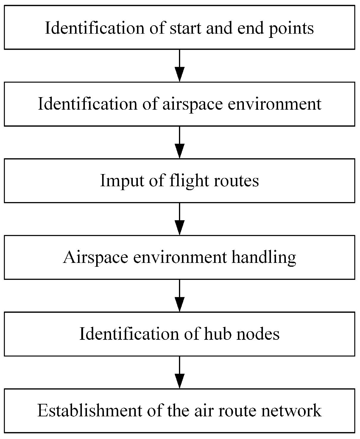
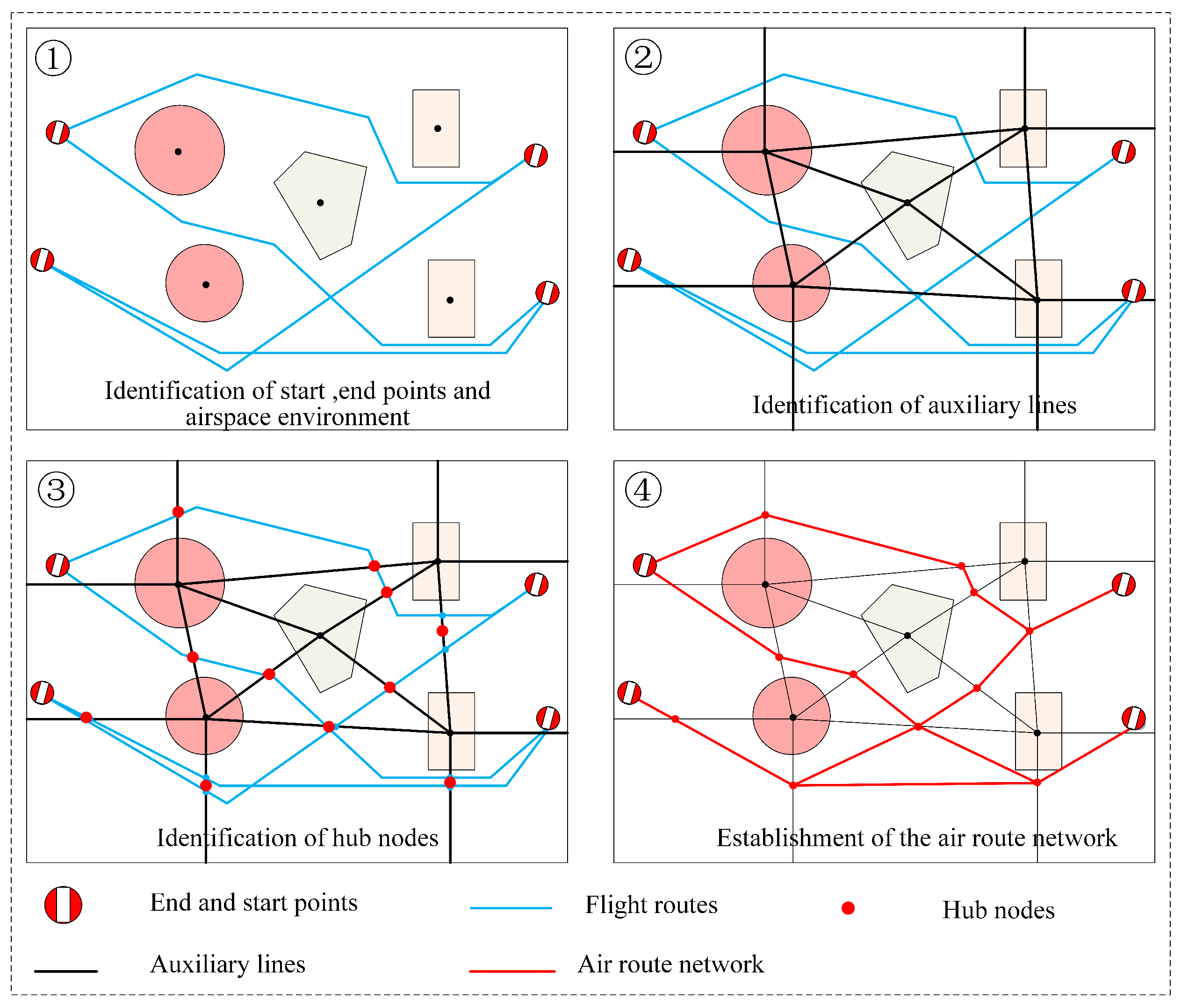
2. The Method for Constructing Urban Air Mobility Route Network Based on Flight Routes
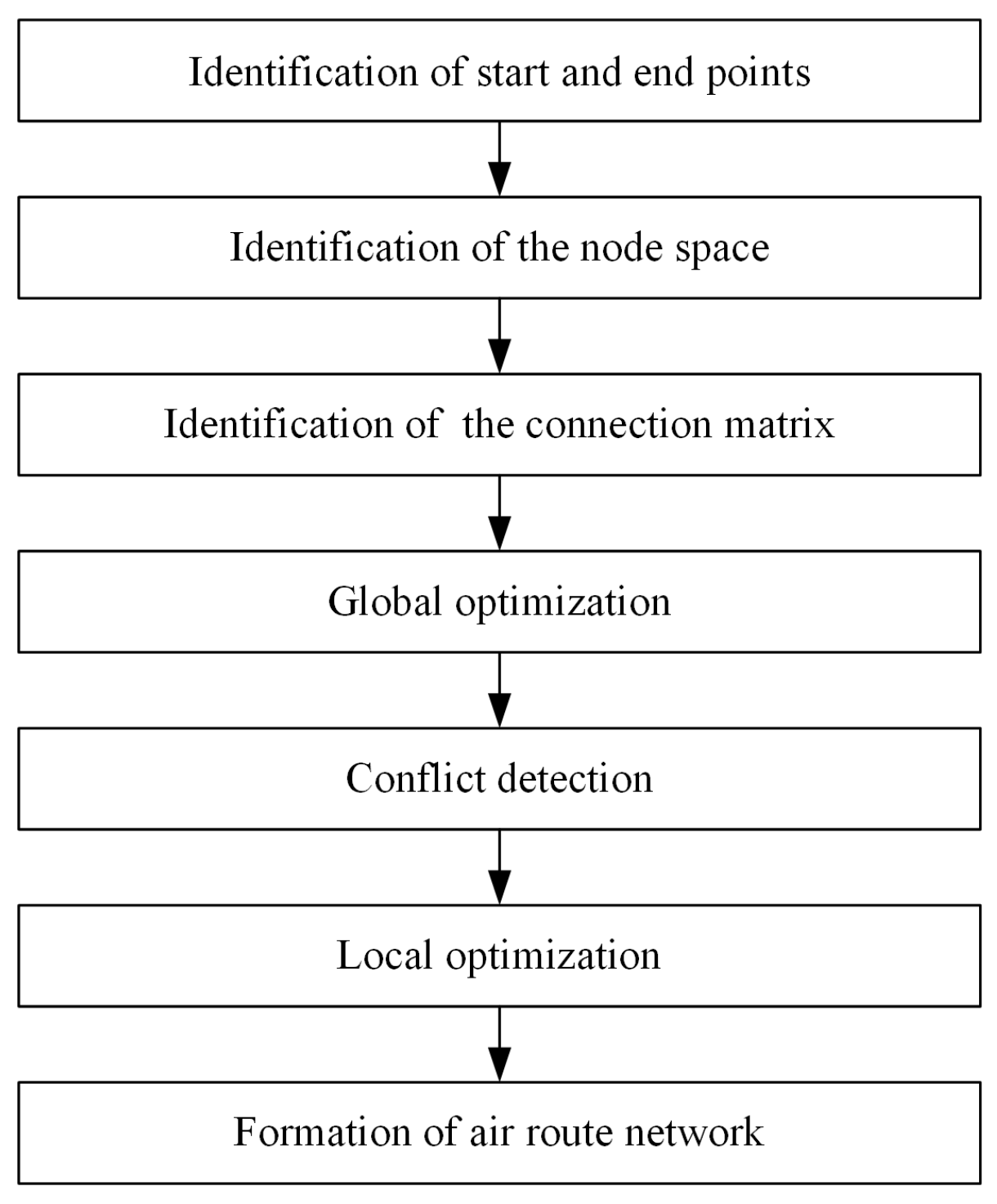
3. The Global Optimization Method for Urban Air Mobility Route Network Based on Node Movement
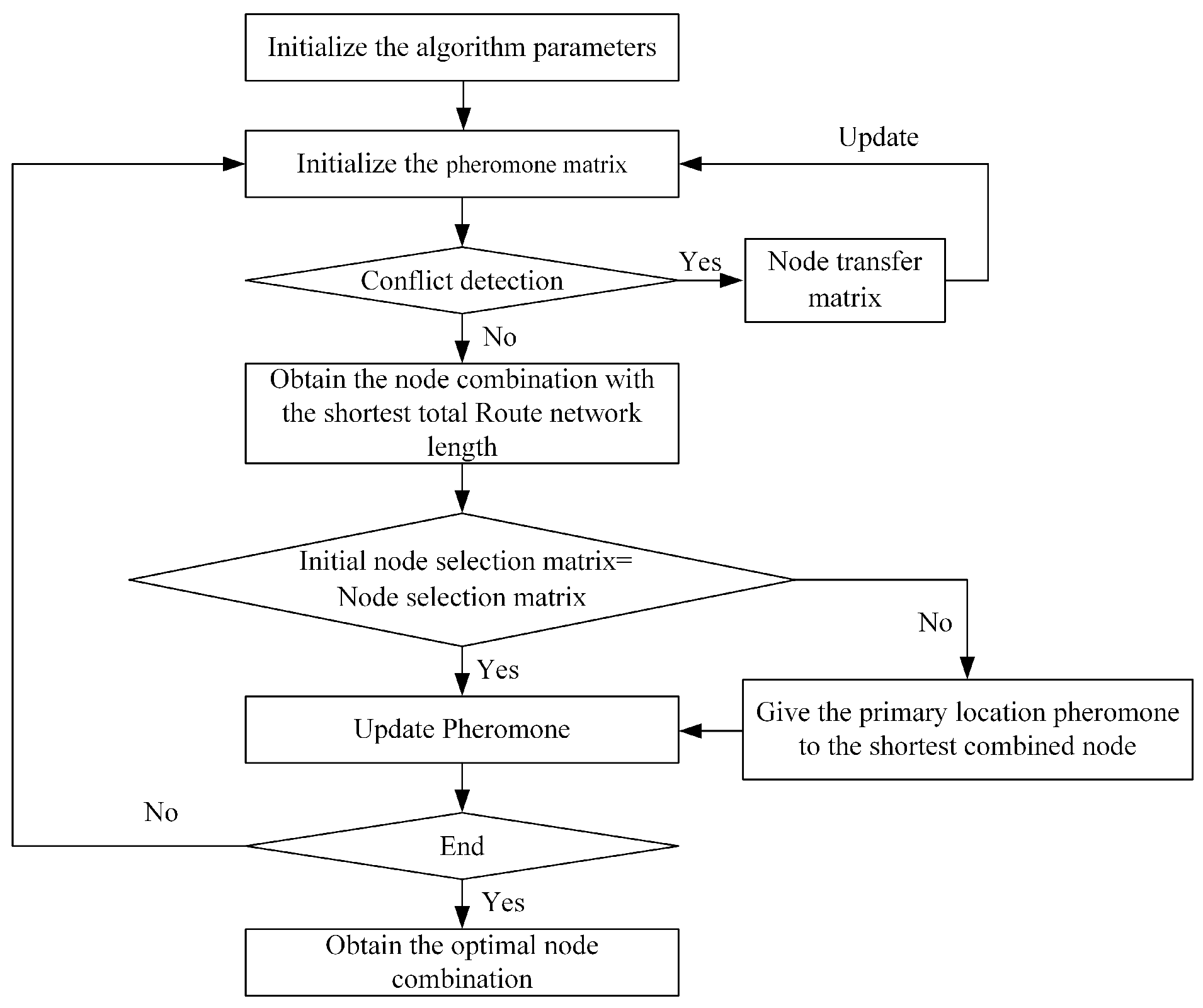
3.1. Optimization Procedure
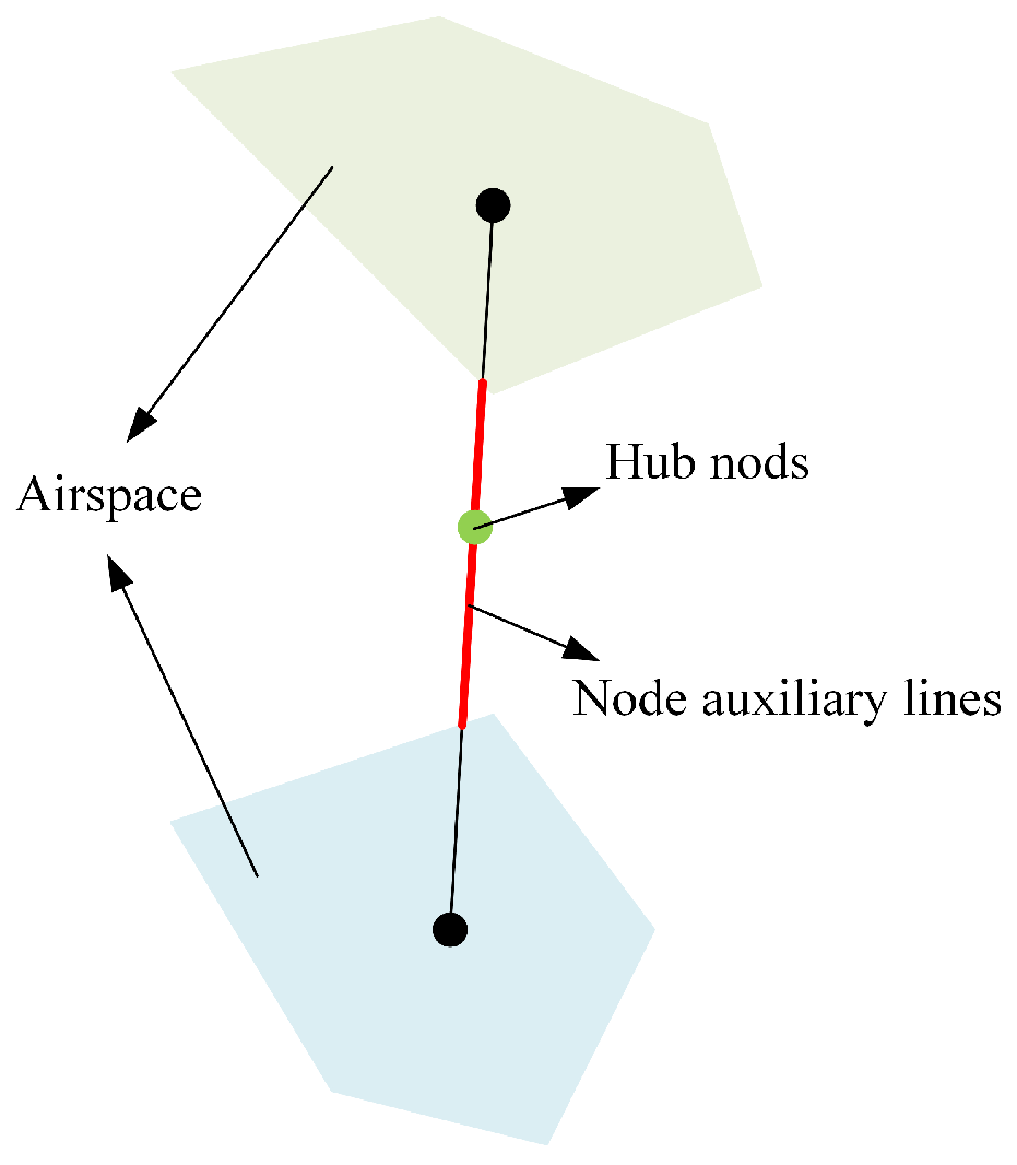
3.2. The Fundamental Principles
- Nodes are selected within the node space based on the connection matrix to create an initial node selection matrix.
- Conflict detection is performed using the connection matrix. If conflicts are identified, a node transition matrix is established based on predefined node transition rules, and the node selection matrix is updated accordingly.
- In scenarios where no conflicts are detected, the node combination with the shortest total network length for the current iteration is determined.
- If modifications occur in the node selection matrix during conflict detection, the pheromone information of the respective nodes in the initial node matrix is allocated to the final node combination, followed by pheromone updating.
3.3. Constraints
3.4. Objective Function
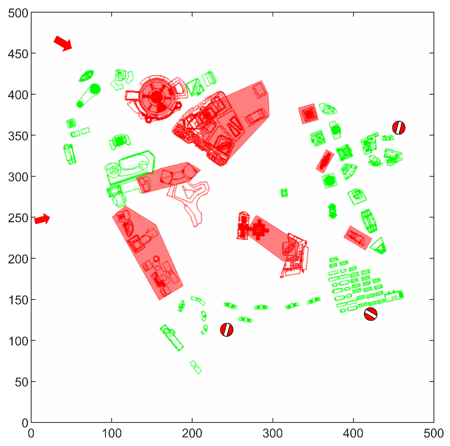
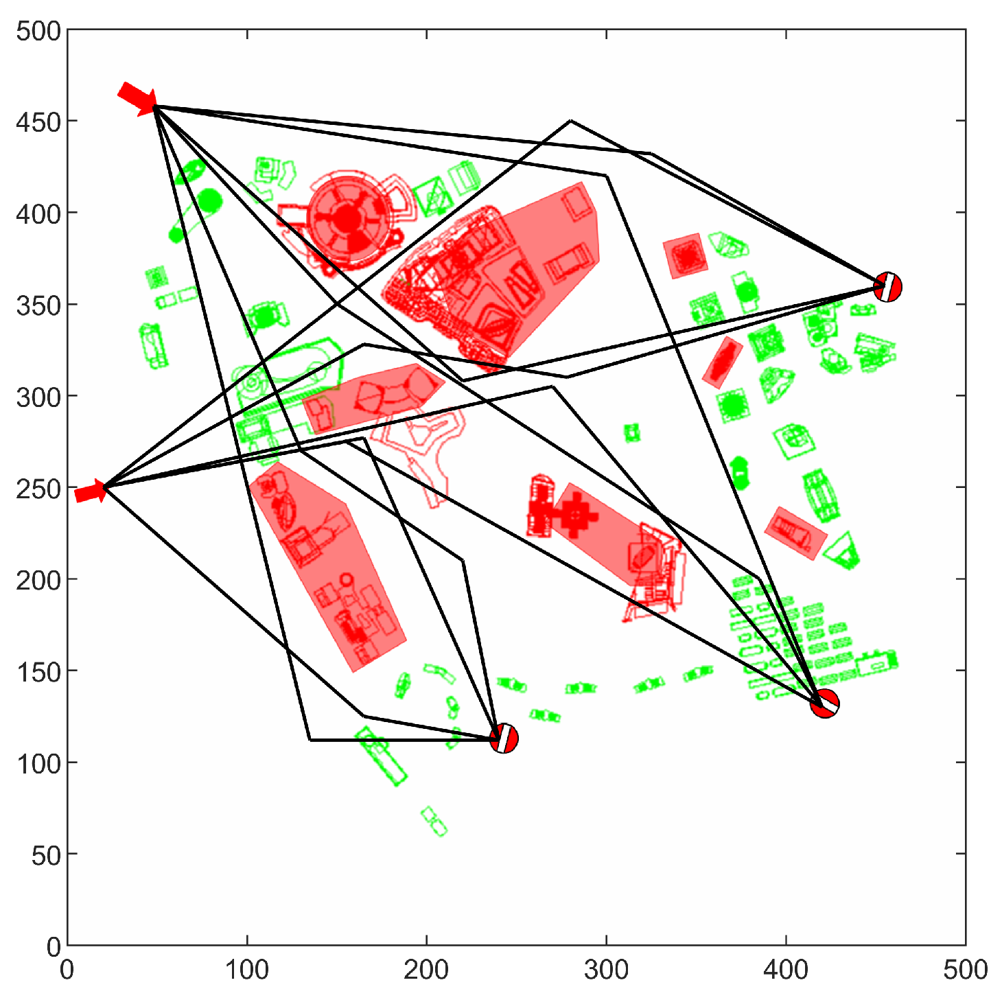
4. The Experimental Demonstration
4.1. Experimental Parameters
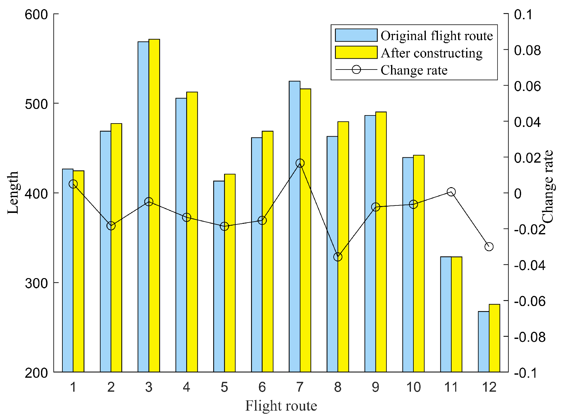
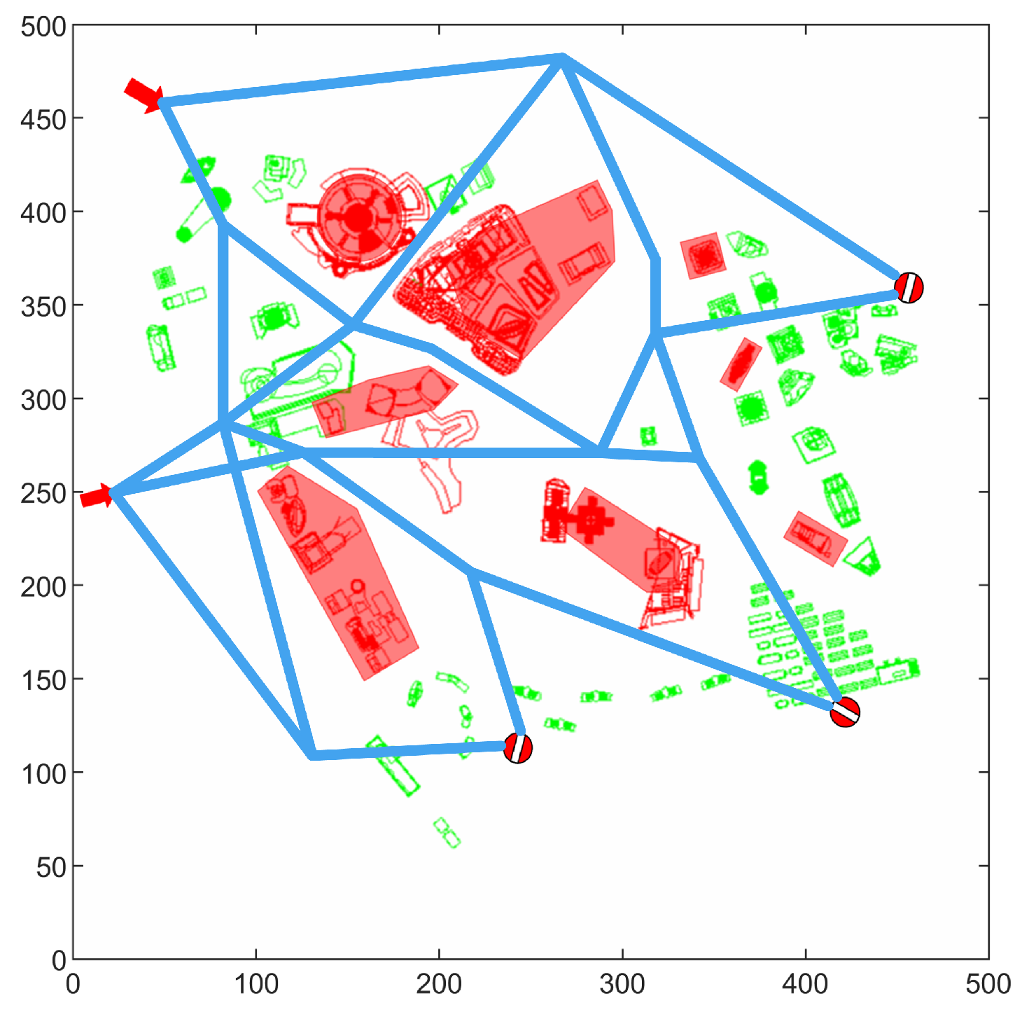
4.2. The Method for Constructing Urban Air Mobility Route Network Based on Flight Routes
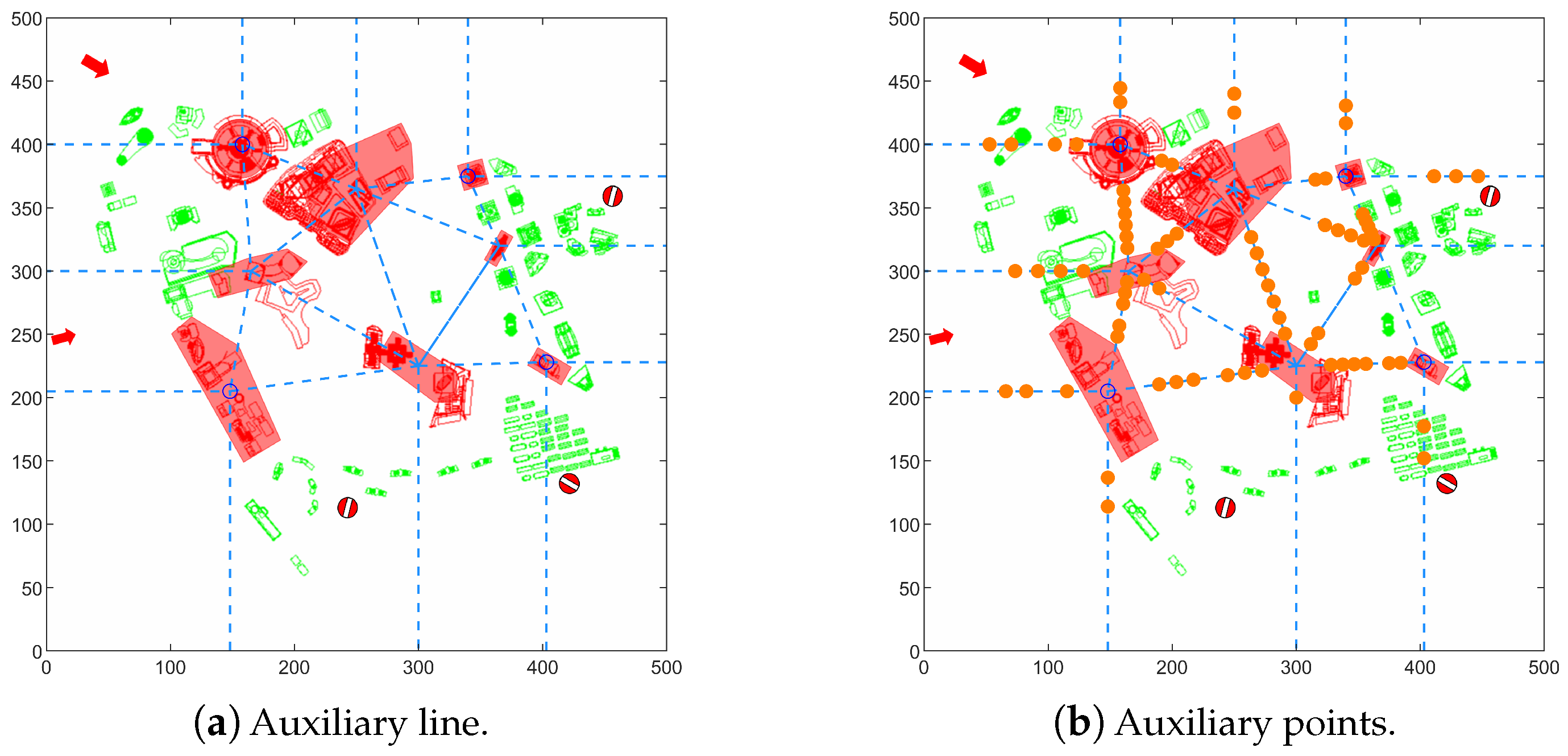
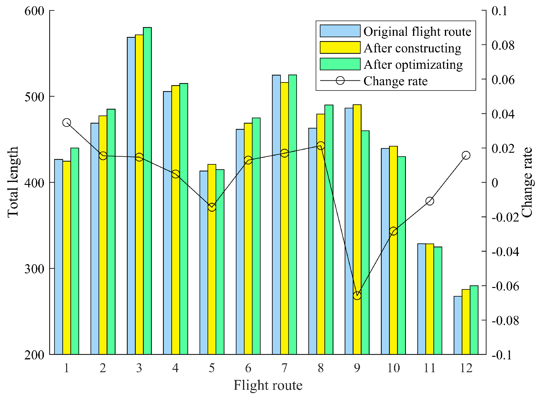
4.3. The Global Optimization Method for Urban Air Mobility Route Network Based on Node Movement
5. Summary
Author Contributions
Funding
Data Availability Statement
Acknowledgments
Conflicts of Interest
References
- Lv, D.; Wang, K.; Qu, X. Urban air traffic: Network structure and Operation Planning. Traffic Constr. Manag. 2023, 2, 78–81. (In Chinese) [Google Scholar]
- Kopardekar, P.; Rios, J.; Prevot, T.; Johnson, M.; Jung, J.; Robinson, J.E., III. Unmanned Aircraft System Traffic Management (UTM) Concept of Operations. In Proceedings of the 16th AIAA Aviation Technology, Integration, and Operations Conference, Washington, DC, USA, 13–17 June 2016. [Google Scholar]
- McKercher, R.G.; Khouli, F.; Wall, A.S.; Larose, G.L. Modelling and Control of an Urban Air Mobility Vehicle Subject to Empirically-Developed Urban Airflow Disturbances. Aerospace 2024, 1, 220. [Google Scholar] [CrossRef]
- Altun, A.T.; Hasanzade, M.; Saldiran, E.; Guner, G.; Uzun, M.; Fremond, R.; Tang, Y.; Bhundoo, P.; Su, Y.; Xu, Y.; et al. AMU-LED Cranfield Flight Trials for Demonstrating the Advanced Air Mobility Concept. Aerospace 2023, 10, 775. [Google Scholar] [CrossRef]
- Ywet, N.L.; Maw, A.A.; Nguyen, T.A.; Lee, J.-W. YOLOTransfer-DT: An Operational Digital Twin Framework with Deep and Transfer Learning for Collision Detection and Situation Awareness in Urban Aerial Mobility. Aerospace 2024, 11, 179. [Google Scholar] [CrossRef]
- Li, Y.; Zhang, S.; He, R.; Holzapfel, F. Objective Detection of Trust in Automated Urban Air Mobility: A Deep Learning-Based ERP Analysis. Aerospace 2024, 11, 174. [Google Scholar] [CrossRef]
- Lu, Z.; Hong, H.; Holzapfel, F. Multi-Phase Vertical Take-Off and Landing Trajectory Optimization with Feasible Initial Guesses. Aerospace 2024, 11, 39. [Google Scholar] [CrossRef]
- Pongsakornsathien, N.; Bijjahalli, S.; Gardi, A.; Symons, A.; Xi, Y.; Sabatini, R.; Kistan, T. A Performance-Based Airspace Model for Unmanned Aircraft Systems Traffic Management. Aerospace 2020, 7, 154. [Google Scholar] [CrossRef]
- Thoughts and Suggestions on Accelerating the Development of Urban Air Mobility in China. Available online: https://www.163.com/dy/article/IA77ECOD05503O4L.html (accessed on 12 June 2024).
- McFadyen, A.; Bruggemann, T. Unmanned Air Traffic Network Design Concepts. In Proceedings of the 2017 IEEE 20th International Conference on Intelligent Transportation Systems (ITSC), Yokohama, Japan, 16–19 October 2017. [Google Scholar]
- Xu, C.; Ye, H.; Yue, H.; Tan, X.; Liao, X. Iterative construction of UAV low-altitude air route network in an urbanized region: Theoretical system and technical roadmap. Acta Geogr. Sin. 2020, 75, 917–930. [Google Scholar]
- Xu, C.; Liao, X.; Ye, H.; Yue, H. Iterative construction of low-altitude UAV air route network in urban areas: Case planning and assessment. J. Geogr. Sci. 2020, 30, 1534–1552. [Google Scholar] [CrossRef]
- Li, S.; Zhang, H.; Yi, J.; Liu, H. A bi-level planning approach of logistics unmanned aerial vehicle route network. Aerosp. Sci. Technol. 2023, 141, 108572. [Google Scholar] [CrossRef]
- Quan, Q.; Li, M.; Fu, R. Sky Highway Design for Dense Traffic. IFAC-PapersOnLine 2021, 54, 140–145. [Google Scholar] [CrossRef]
- Li, J.; Shen, D.; Yu, F.; Zhang, R. Air Channel Planning Based on Improved Deep Q-Learning and Artificial Potential Fields. Aerospace 2023, 10, 758. [Google Scholar] [CrossRef]
- Dai, F.; Wan, X. Backrunk route network planning method. Sci. Technol. Eng. 2014, 14, 271–276. (In Chinese) [Google Scholar]
- Tan, Q.; Wang, Z.; Ong, Y. Evolutionary Optimization-based Mission Planning for UAS Traffic Management (UTM). In Proceedings of the 2019 International Conference on Unmanned Aircraft Systems (ICUAS), Atlanta, GA, USA, 11–14 June 2019. [Google Scholar]
- Mohamed Salleh, M.F.B.; Wanchao, C.; Wang, Z.; Huang, S.; Tan, D.Y.; Huang, T.; Low, K.H. Preliminary Concept of Adaptive Urban Airspace Management for Unmanned Aircraft Operations. In Proceedings of the 2018 AIAA Information Systems-AIAA Infotech @ Aerospace, Kissimmee, FL, USA, 8–12 January 2018. [Google Scholar]
- Zhang, H.; Tian, T.; Feng, O.; Wu, S.; Zhong, G. Research on Public Air Route Network Planning of Urban Low-Altitude Logistics Unmanned Aerial Vehicles. Sustainability 2023, 15, 12021. [Google Scholar] [CrossRef]
- Li, S.; Zhang, H.; Li, Z.; Liu, H. An Air Route Network Planning Model of Logistics UAV Terminal Distribution in Urban Low Altitude Airspace. Sustainability 2021, 13, 13079. [Google Scholar] [CrossRef]
- He, X.; He, F.; Li, L.; Zhang, L.; Xiao, G. A route network planning method for urban air delivery. Transp. Res. Part E Logist. Transp. Rev. 2022, 166, 102872. [Google Scholar] [CrossRef]
- Ye, M.; Zhao, J.; Guan, Q.; Zhang, X. Research on eVTOL Air Route Network Planning Based on Improved A* Algorithm. Sustainability 2024, 16, 561. [Google Scholar] [CrossRef]
- Li, J.; Wu, M.; Wen, X. Identification of key nodes and connected edges in complex networks based on the minimum connected dominance set. Syst. Eng. Electron. 2019, 41, 2541–2549. (In Chinese) [Google Scholar]
- Cai, K.; Zhang, J.; Zhou, C. Optimization of the Crossing Waypoints in Air Route Network. In Proceedings of the 29th Digital Avionics Systems Conference, Salt Lake City, UT, USA, 3–7 October 2010. [Google Scholar]
- Wang, S.; Cao, X.; Li, H.; Li, Q.; Hang, X.; Wang, Y. Air route network optimization in fragmented airspace based on cellular automata. Chin. J. Aeronaut. 2017, 30, 1184–1195. [Google Scholar] [CrossRef]
- Saxena, A.; Prasad, M.; Gupta, A.; Bharill, N.; Patel, O.P.; Tiwari, A.; Joo, E.M.; Weiping, D.; Chin-Teng, L. A review of clustering techniques and developments. Neurocomputing 2017, 267, 664–681. [Google Scholar] [CrossRef]
- Soni Madhulatha, T. An Overview on Clustering Methods. IOSR J. Eng. 2012, 4, 719–725. [Google Scholar] [CrossRef]
- Zhang, W.; Lu, T. The Research of Genetic Ant Colony Algorithm and Its Application. Procedia Eng. 2012, 37, 101–106. [Google Scholar] [CrossRef]
- Hu, W.; Wu, K.; Shum, P.P.; Zheludev, N.I.; Soci, C. All-Optical Implementation of the Ant Colony Optimization Algorithm. Sci. Rep. 2016, 6, 26283. [Google Scholar] [CrossRef] [PubMed]


| Parameter | Value | Parameter | Value |
|---|---|---|---|
| 0.1 | Maximum iteration times | 100 | |
| 0.8 | Heuristic function factor | 1 | |
| a | 10 | Pheromone constants | 0.14 |
| n | 10 |
Disclaimer/Publisher’s Note: The statements, opinions and data contained in all publications are solely those of the individual author(s) and contributor(s) and not of MDPI and/or the editor(s). MDPI and/or the editor(s) disclaim responsibility for any injury to people or property resulting from any ideas, methods, instructions or products referred to in the content. |
© 2024 by the authors. Licensee MDPI, Basel, Switzerland. This article is an open access article distributed under the terms and conditions of the Creative Commons Attribution (CC BY) license (https://creativecommons.org/licenses/by/4.0/).
Share and Cite
Li, J.; Shen, D.; Yu, F.; Qi, D. A Method for Air Route Network Planning of Urban Air Mobility. Aerospace 2024, 11, 584. https://doi.org/10.3390/aerospace11070584
Li J, Shen D, Yu F, Qi D. A Method for Air Route Network Planning of Urban Air Mobility. Aerospace. 2024; 11(7):584. https://doi.org/10.3390/aerospace11070584
Chicago/Turabian StyleLi, Jie, Di Shen, Fuping Yu, and Duo Qi. 2024. "A Method for Air Route Network Planning of Urban Air Mobility" Aerospace 11, no. 7: 584. https://doi.org/10.3390/aerospace11070584
APA StyleLi, J., Shen, D., Yu, F., & Qi, D. (2024). A Method for Air Route Network Planning of Urban Air Mobility. Aerospace, 11(7), 584. https://doi.org/10.3390/aerospace11070584