Article

Simulation and Experimental Study of Gas Turbine Blade Tenon-Root Detachment on Spin Test

1
Ocean College, Zhejiang University, Zhoushan 316021, China
2
AECC Hunan Aviation Powerplant Research Institute, Zhuzhou 412002, China
3
College of Energy Engineering, Zhejiang University, Hangzhou 310027, China
4
Zhejiang Hiro Aeronautics Technology Co., Ltd., Deqing 313219, China
*
Author to whom correspondence should be addressed.
Aerospace 2024, 11(8), 629; https://doi.org/10.3390/aerospace11080629
Submission received: 29 June 2024 / Revised: 28 July 2024 / Accepted: 30 July 2024 / Published: 1 August 2024

Abstract

:
This paper addresses the critical issue of turbine blade containment in aircraft engines, crucial for ensuring flight safety. Through a comprehensive approach integrating numerical simulations and experimental validations, the containment capabilities of gas turbine engine casings are thoroughly analyzed. The study investigates the impact dynamics, deformation characteristics, and energy absorption mechanisms during blade detachment events, shedding light on the containment process. Based on the multi-stage nature of gas turbines, two different blade structures were designed for turbine blades. Utilizing finite element simulation and the Johnson–Cook constitutive equation, this study accurately simulated single-blade and dual-blade containment scenarios. The simulation results of the single blade indicate that the process of a gas turbine blade impacting the casing primarily consists of three stages. The second stage, where the tenon root strikes the casing, is identified as the main cause of casing damage. Meanwhile, in the dual-blade simulation, the second blade, influenced by the first blade, directly impacts the casing after fracturing, resulting in greater damage. Then, eight corresponding containment tests were conducted based on the simulation results, validating the accuracy of the simulation parameters. Experimental verification of simulation results further confirms the validity of the proposed containment curves, providing essential insights for optimizing casing design and enhancing the safety and reliability of aircraft engines.

1. Introduction

Aircraft gas turbine engines are high-speed rotating thermal-power mechanical devices known for their smooth operation, compact structure, high thermal efficiency, and rapid start-up. Blades, as pivotal components within gas turbines, undertake the critical role of energy conversion. Blade malfunction constitutes approximately 42% of overall engine failures per statistics and stands out as a typical failure in key mechanical components of gas turbines [1]. An essential safety concern regarding aircraft engines lies in the potential hazards posed by non-containment failure of high-speed rotating parts to the aircraft, crew, and passengers [2,3]. During operation, failed rotor components can generate high-speed, high-energy fragments capable of impacting the engine casing. If the casing lacks adequate strength, it risks penetration, potentially causing further damage to surrounding equipment, thus posing a severe threat to flight safety [4]. Both civil and military aviation engine specifications rigorously address containment. Examples include the Federal Aviation Regulations (FAR-33), the Engine Structural Integrity Outline (MIL-STD-1783B), and the European Aviation Engine Certification Specification (CS-E 810), which outline test verification requirements for turbine blade failure [5,6,7]. The Civil Aviation Administration of China has also outlined technical requirements for blade containment in CCAR-33 [8].
In recent years, numerous aircraft accidents worldwide have been caused by non-containment failures. In May 2011, a non-containment incident occurred on a Korean Air Airbus A330-300, where the low-pressure turbine casing of the PW4168 engine on the right side sustained severe damage from impacting blade clusters, leading to a gap [9]. In June 2017, a non-containment incident occurred during the climb phase on a Skywest Canadair CRJ-700 aircraft equipped with a GECF34 engine. Fragments of the low-pressure turbine blades penetrated the casing and left marks on the fuselage, as shown in Figure 1 [10].
As a result, numerous researchers have conducted a series of studies on the containment of blade shedding. Previously, multiple researchers have conducted studies investigating the effects of a released blade on a containment ring under different circumstances. Teng et al. [11] studied how fragment parameters influence the impact response of a containment ring. Qiu et al. [12] studied the impact of blade rubbing caused by blade shedding on the fatigue life of the casing. He et al. [13] conducted experimental and simulation studies on titanium alloy axial compressor blades and stainless steel simulated casings. Jiang et al. [14] analyzed the engine containment test methods for high-bypass turbofan engines and explained the blade release explosion methods. Xuan et al. [15] studied the application of Kevlar composite material in the containment system of aircraft engine fan blades, conducted rotational impact tests and numerical simulations, and analyzed its energy absorption and containment capabilities. He et al. [16] derived an empirical critical equation describing the relationship between the kinetic energy release of fan blades and the thickness of Kevlar fabric through summarizing tests and simulation results. Bai et al. [17] studied the impact of the groove depth in U-shaped casings under turbine disk fragment conditions on the containment performance. Sengoz et al. [18] established a general computational model for the gas turbine engine following a fan blade-out (FBO) event in the FAA report. Tuninetti et al. [19] developed a computational model using the Johnson–Cook plasticity and damage model to simulate the mechanical behavior of Ti64 alloy in turbofan engine blade containment tests. Yang et al. [20] conducted simulation analyses comparing the containment capabilities of single-layer, double-layer, and honeycomb sandwich structure casings. He et al. [21] utilized numerical simulations to investigate the multi-blade effect of turbine blades, revealing that the complexity of casing structures may enhance the containment capability when blades deviate from the rotation plane, impacting other protruding parts of the casing. Sinha et al. [22] employed LS-DYNA to establish a whole-engine model, studying secondary damage after blade impact, analyzing the containment process and dynamic responses of bearings, unbalance, rotor-casing wall friction, and other engine components. Eryilmaz et al. [23] conducted numerical simulations on blade impact on containment rings after turbine rotor failure, analyzing the relationship between the containment coefficient and factors such as blade tip structure, number of broken blades, and casing inclination, proposing a method to correct containment engineering design calculations. VanderKlok et al. [24] proposed a small-scale fan-blade shedding test method, weakening the rotor through pre-existing cracks and conducting containment tests for single-blade shedding, single-blade influenced by trailing blades, and rotor disk failure. Kraus et al. [25] conducted finite element calculations using LS-DYNA to study turbine casing containment tests, investigating blade shape, neighboring blade effects, and material mechanics under impact conditions. Roy et al. [26] utilized three-dimensional finite element analysis to propose a dual-ring design, studying the interaction between shed blades and remaining blades, suggesting that this design ensures high-energy absorption and impact resistance, significantly reducing damage to the fan disk.
Despite significant achievements in the study of containment characteristics for aircraft engines, most research has focused on fan blade containment. Studies on turbine blade containment are relatively scarce and often employ air cannon impact tests. Due to cost and technical constraints, rotational test rigs are seldom used, and there is a lack of detailed investigations into the impact process, deformation, and failure modes. Moreover, there is even less research conducted on blade rotational detachment tests in high-temperature environments. Therefore, this study designed two types of gas turbine blades, with different blade lengths and widths but consistent tenon root structures corresponding to the characteristics of different stages of gas turbine blades. This was performed to investigate the sensitivity of blade length and width to containment in the engine casing. The design of the blades in this study is based on a newly designed turboshaft engine. This engine can achieve a power output of up to 1350 kilowatts, with a gas turbine casing temperature of approximately 635 °C. Furthermore, to investigate the impact of subsequent blade failure due to the collision with previously detached blades on the containment of the casing, simulations and experiments of dual-blade containment were conducted. This paper systematically investigated the containment issue of aero-engine turbine casings. It analyzed the trajectory of released blades, deformation of the blades and casing, and the energy change pattern during the impact response process, based on numerical simulation and experimental verification results.
The main content of the article is summarized as follows. In Section 2, the thickness of the casings for gas turbine engines equipped with blades A and B, featuring two different blade structures, was estimated using the conventional containment coefficient method. Additionally, their containment capabilities are simulated based on the J-C (Johnson–Cook) model. In Section 3, the effectiveness of simulation parameters through containment tests of the gas turbine blades A and B is validated. In Section 4, the damage resulting from the impact of single- and dual-blade detachment on the casing is discussed. The containment curve of this type of gas turbine engine is plotted to support the improvement, modification, and development of in-service engine models and next-generation engines. Section 5 provides a summary of key conclusions drawn from this work.

2. Numerical Simulation

2.1. Containment-Coefficient Methods

It is necessary to estimate the critical containment thickness of the gas turbine engine casing before conducting numerical simulation. The containment coefficient method, proposed by Rolls-Royce, is a common approach for calculating containment characteristics. According to the containment determination formula in the EGD-3 stress standard, the containment of the blades is determined by the relationship between the kinetic energy of the blades and the containment coefficient of the casing [27].
The containment coefficient of the casing can be determined using the following formula:
C A = B ( σ b δ t 2 ) C R = E k ( 0.0125694 1.920137 × 10 8 E k + 4.840234 × 10 11 E k 2 ) n c = C A C R
where B is the length of the broken part of the blade, σb is the ultimate strength of the casing material, δ is the elongation of the casing material, t is the average thickness of the casing corresponding to the rotor blades, CR is derived from fitting the containment curve based on the Spay MK202 engine. When the containment coefficients nC > 1, nC = 1, and nC < 1, they correspond to containment, critical containment, and non-containment states, respectively.
In the context of this study, two types of turbine blades, A and B, were designed based on the multi-stage blade characteristics of gas turbines, depicted in Figure 2. These two blade designs represent typical first-stage and second-stage high-pressure turbine blades. The first-stage blades are shorter and wider, while the second-stage blades are longer and narrower. The study investigated how blades A and B affect the containment capability of the casing when a single blade fractures. The blades A and B have different blade body dimensions. The blade A has a relatively wider but shorter blade body, while the blade B has a narrower but longer blade body. The turbine blade A has a blade length of 20 mm and a width of 19 mm. And the turbine blade B has a blade length of 26 mm and a width of 15 mm. Therefore, the sensitivity of the blade body dimensions on the casing containment is studied. Based on the actual structure of the gas turbine engine, it is assumed that there is a 2 mm gap between the turbine blade tips and the inner wall of the casing. Therefore, the inner wall diameters for casings A and B are, respectively, DA = 195 mm and DB = 207 mm, with a casing height of h = 62 mm. To ensure that the release energy of the two types of blades is the same, the operating speeds of the blade A and the blade B are 47,500 r/min and 50,000 r/min, respectively. Using the parameters of the actual blades and the containment coefficient method, the casing thicknesses of A and B are calculated to be t1 = 2.37 mm and t2 = 2.12 mm, respectively, when nC =1, representing the critical containment condition. The schematic diagram of the casing is shown in Figure 3.

2.2. Containment Simulation Analysis

Given the primary focus of this paper is on casing damage and containment characteristics, it is crucial to ensure that the simulated energy associated with a gas turbine single-blade fracture aligns with real-world scenarios. For the simulation of single-blade detachment, the impact process is not influenced by the turbine disc or multiple blades; hence, only a single-blade and casing models are established in the numerical simulation. In the simulation of dual-blade detachment, the blade disk is simplified to a ring. Additionally, for better comparison of the different damage caused by the impact of the two blades on the casing, the two blades are installed opposite each other at 180°. It ensures that the impact areas of the two blades after release are not continuous. GH4169, classified as a nickel-based high-temperature alloy, is chosen for its outstanding performance under moderate to high temperatures and high resistance to corrosion, providing ample rigidity during blade impacts and widely applied in components such as turbine casings in aero-engines. The material selected for gas turbine blades is K417, classified as nickel-based high-temperature casting alloy with high strength characteristics. Hexahedral meshes offer superior computational accuracy, deformation characteristics, mesh granularity, and resistance to deformation compared to tetrahedral meshes. However, tetrahedral meshes offer a simple division method and strong adaptability to boundaries, making them suitable for various complex geometric models. Throughout the simulation process, the casing is prioritized as the primary analytical object, utilizing high-quality hexahedral meshes with a minimum of four layers arranged in the casing’s thickness direction. Appropriate stiffness and viscous form of hourglass controls are implemented to reduce hourglass energy. Figure 4 illustrates the finite element simulation models for both single-blade and dual-blade configurations. Tetrahedral mesh is employed for the gas turbine blades, with 16,420 elements for the blade A and 15,440 elements for the blade B. Additionally, an eight-node hexahedral mesh is utilized for the casing A, comprising 249,120 elements, and 334,000 elements for the casing B. In the dual-blade model, the blade attachment ring is also meshed using hexahedral elements. One of the blades is freely detached in flight, while the other blade is set to have bound contact with the ring. The upper flange of the casing is constrained with fixed boundary conditions. The gas turbine blade A is subjected to a prestress to accommodate centrifugal loading at a maximum operating speed of 47,500 r/min. The gas turbine blade B is subjected to centrifugal loading at 50,000 r/min. We apply a thermal load of 635 °C to the casing according to the actual working environment of the turbine blades. The calculation time is 3 ms, with a time step of one hundred.
Numerical simulations of gas turbine casing containment were conducted using LS-DYNA R14.0 software, employing the Johnson–Cook constitutive equation [28]. This model is widely recognized for its accurate representation of material behaviors such as strain hardening, strain rate sensitivity, and thermal softening. The equation is formulated as:
σ e = A + B ε e P n 1 + C l n ( ε ˙ * ) 1 T *
where σe is Von Mises equivalent stress. ε e p is the equivalent plastic strain. ε ˙ * is the dimensionless equivalent plastic strain rate. ε* = ε*/ε0, ε 0 ˙ is the reference strain rate. ε* is the current strain rate. T* is a dimensionless temperature. A, B, n, C, and m are material constants. A is the yield stress. B and n are strain-hardening effects. C is the strain rate constant, and m is the temperature constant. This model plays a critical role in predicting material response under complex loading conditions, essential for evaluating structural integrity and failure analysis. The Johnson–Cook cumulative damage criterion, rooted in continuous damage mechanics [29], incorporates a damage parameter D defined as:
D = 1 / ε f d ε e p
where failure strain is defined as:
ε f = D 1 + D 2 e D 3 σ * 1 + D 4 ln ε ˙ * 1 + D 5 T *
where σ* = P/σeff = −Rσ is the mean value of principal stress under hydrostatic pressure, σeff is Von Mises-equivalent stress, Rσ is stress triaxial degree, and D1~D5 is the failure constant. Detailed information regarding the specific values of the Johnson–Cook model parameters is available in our previous work [30,31], and a summary of these parameters is presented in Table 1.

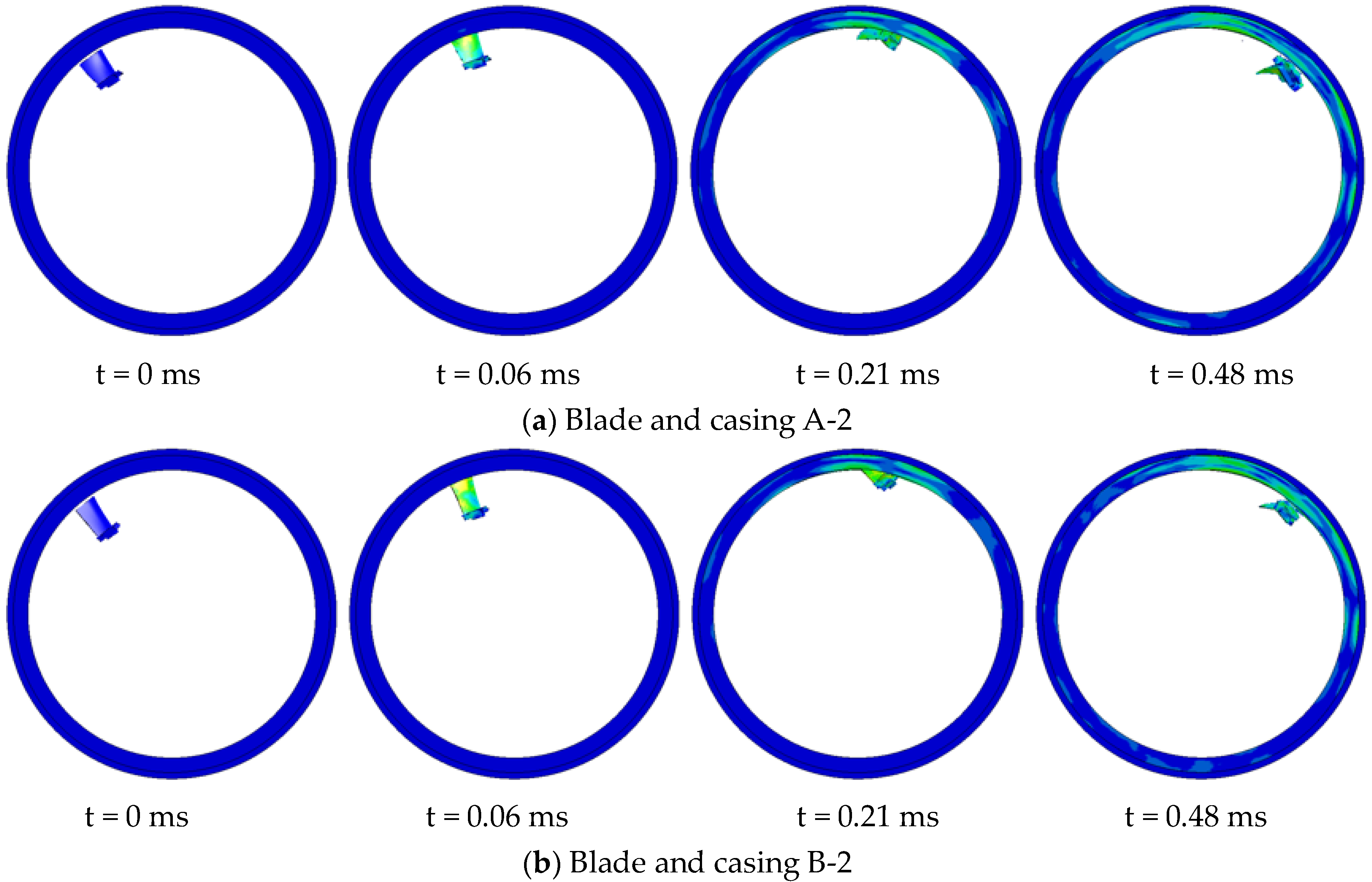
2.2.1. The Single-Blade Containment Numerical Simulation

Figure 5 presents the numerical simulation results of a single gas turbine blade A releasing off and impacting the containment casing. Figure 6 illustrates the variation in kinetic and internal energy of the turbine blade A and casing during the impact process. At 0.06 ms, the gas turbine blade A makes initial contact with the casing, with localized regions of the blade experiencing compression, bending, and subsequent failure, leading to a decrease in kinetic energy. As the blade moves, the blade tip strikes the casing, forming a slender crack. By 0.18 ms, severe damage occurs at the blade tip, causing the blade to flip along its axis and strike the casing with maximum impact force, resulting in rapid tearing of the casing and the initiation of cracks, which subsequently propagate along the direction of blade movement, forming gaps. At 0.48 ms, the internal energy of the casing reaches its maximum, accompanied by maximal damage, and fragments of the blade are ejected from the gap. Therefore, the numerical simulation results of this event are considered non-containment, and this simulation is labeled as A-1.
Figure 7 depicts the numerical simulation results of a single gas turbine blade B flying off and impacting the containment casing. Figure 8 illustrates the variation of kinetic and internal energy of the turbine blade B and casing during the impact process. Similar to the blade A detachment process, at 0.06 ms, the gas turbine blade B makes initial contact with the casing. By 0.21 ms, the blade flips along its axis and impacts the casing with the root, causing a bulge on the casing. As the blade impact progresses, the bulge continues to enlarge, eventually forming a small breach. At 0.48 ms, the internal energy of the casing reaches its maximum, but no blade fragments are ejected from the breach. Therefore, this numerical simulation is considered to be in the critical containment state, and it is labeled as B-1. At the same time, this paper defines a state where the casing has small breach but no blade fragments escape as the critical containment state.
Figure 5. Process of the turbine blade pieces impacting the casing A-1.
Aerospace 11 00629 g005
Figure 6. Energy changes during the impact A-1.
Aerospace 11 00629 g006
Figure 7. Process of the turbine blade pieces impacting the casing B-1.
Aerospace 11 00629 g007
Figure 8. Energy changes during the impact B-1.
Aerospace 11 00629 g008
Combining the simulation equivalent stress distribution and the energy change graph during impact, we can observe that the impact of the gas turbine blades A and B on the casing mainly consists of three stages. The first stage involves the collision between the blade tip and the casing, the second stage involves the root of the blade impacting the casing, and the third stage involves the blade sliding along the inner wall of the casing after impact. From the energy change graph, it is evident that the internal energy change of the casing during the second stage is greater than that during the first stage, indicating that the damage to the casing is primarily caused by the blade root impact during the second stage of the impact process. Comparing the kinetic energy change of the first stage of the gas turbine blades A and B, it can be seen that the loss ratio of kinetic energy in the first stage of the blade B is greater than that of the blade A. This is because the blade B has a longer blade body, resulting in a longer duration of impact during the first stage, leading to a relatively smaller proportion of energy from the blade root impact during the second stage. Therefore, the results demonstrate a containment state.
Based on the numerical simulation results of the gas turbine blade A, it was observed that at a casing thickness of t = 2.37 mm and a blade rotational speed of 47,500 r/min, the fractured blade impact on the casing resulted in the formation of a significant gap, indicating a non-containment state. To investigate containment under this casing thickness, the blade rotational speed was reduced to 95% of the original value, resulting in a speed of 45,125 r/min. At this reduced speed, the energy of the fractured blade A is 90% of its original value. This simulation is documented as simulation ID A-2. Similarly, the rotational speed of the blade B was reduced to 95% of its original value, resulting in a speed of 47,500 r/min. The casing thickness remained unchanged to investigate the containment of the blade B, and the simulation is documented as simulation ID B-2. The numerical simulation results of blades A and B impacting the casing after changing the rotational speed are shown in Figure 9. Figure 10 depicts the energy variation for A-2 and B-2.
The impact processes of simulations A-2 and B-2 are similar to those of A-1 and B-1, primarily divided into the same three stages. Figure 11 illustrates the damage results of the four simulations. It can be observed that on the A-1 casing, there is one crack and one larger notch damage. On the B-1 casing, there is one bulge and one small breach. Similarly, on the A-2 casing, there is also one bulge and a small breach. However, on the B-2 casing, there are only two bulges without any notches.
To prove the independence of the simulation results from the mesh size, we modified only the element mesh size of the A-2 simulation model according to the A-2 simulation settings. The minimum element size of blade A was increased from 0.25 mm to 0.5 mm, resulting in 9999 elements. The element size of the casing was increased from 0.5 mm to 1 mm, resulting in 102,960 elements, as shown in Figure 12. This modified simulation is referred to as A-2*. Figure 13 shows the simulation results of the casing damage for A-2*. It can be seen that the casing in A-2* is also in a critical containment state, consistent with the A-2 simulation results. Therefore, it proves the independence of the results from the number of elements.

2.2.2. The Dual-Blade Containment Numerical Simulation

The dual-blade model was set up to investigate the damage caused to the casing by subsequent blades following the detachment of a blade due to impact and to compare with the single-blade model. The rotational speeds were set the same as the single-blade model: A-3 at 47,500 r/min, B-3 at 50,000 r/min, A-4 at 45,125 r/min, and B-4 at 47,500 r/min. To distinguish between the damage caused by the first and second blades to the casing, the blades were installed in a 180° opposing configuration. The simulation process of the second blade of the dual-blade model impacting the casing is illustrated in Figure 14. The simulation processes of the four dual-blade models are generally consistent. Initially, they follow the same impact process as the single-blade model: the first blade impacts the casing, flips, and hits the casing with its root, then slides along the inner wall of the casing for a certain distance. At 0.99 ms, the second blade impacts the detached first blade and then detaches itself, followed by flipping. At 1.17 ms, the second blade impacts the casing directly with its root, causing casing damage. Both blades then slide along the inner wall of the casing. Figure 15 illustrates the damage results of the four dual-blade model simulations. The left column displays the damage caused by the first blade impacting the casing, while the right column shows the damage caused by the second blade.
From the simulation result figures, it can be observed that A-3, B-3, and A-4 all have a large breach on the casing, indicating non-containment. However, B-4 only exhibits a bulge, suggesting containment in this case. The finite element simulation results for all eight cases are presented in the Table 2 below.

3. Test Verification

3.1. Containment Test Set-Up

To validate the accuracy of the simulation results presented in Section 2, eight corresponding containment tests were conducted for both gas turbine blades A and B. In the single-blade test, a single blade and a counterweight block were mounted at 180° position, while in the dual-blade test, two blades were installed 180° apart on the disk. The containment ring A had a thickness of 2.37 mm, while the containment ring B had a thickness of 2.12 mm, as in the simulation model. The overall structure and testing system for the containment tests are depicted in Figure 16. The simulated disc was connected to the slave shaft of the test stand as shown in Figure 17. Meanwhile, ceramic heaters and insulation cotton were wrapped around the outside of the casing, heating the outer wall of the casing to 635 °C to simulate the high-temperature working environment of the turbine blades. Pre-cut grooves were employed to control the fly-off speed of the gas turbine blades, ensuring that they flew off at the respective target speeds.
The testing control system comprises three main components: the trigger signal system, the speed measurement and control system, and the high-speed camera system. Before the test, trigger wires are wound around the outer wall of the containment ring. When the blade flies off, the trigger wire wound on the containment ring is cut upon impact, generating a trigger signal. This signal triggers the speed control system, allowing the test stand to decelerate and stop promptly. Simultaneously, triggers installed on the bottom of the test stand activate high-speed cameras to record data. The sampling frequency of the high-speed cameras is set at 33 kfps to ensure capturing the rupture process accurately.

3.2. Experimental Results

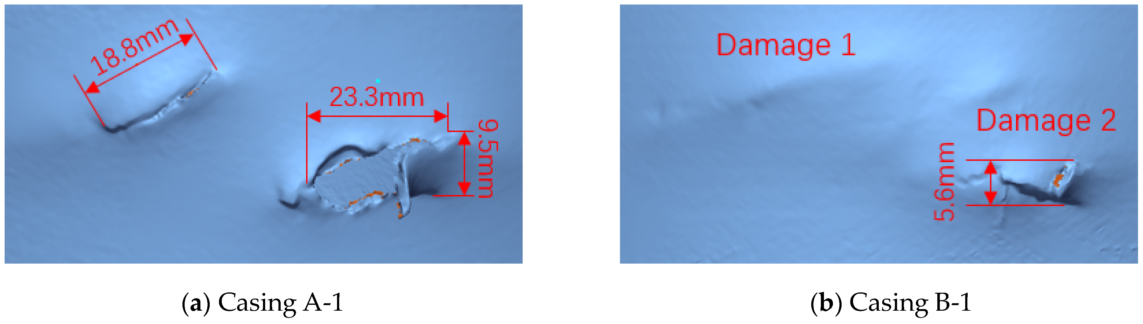
3.2.1. The Single-Blade Containment Test Results

Figure 18a,b depict the single-blade containment tests A-1 and B-1 of gas turbine blades A and B, respectively, at fly-off speeds of 47,500 r/min and 50,000 r/min. According to the high-speed camera recordings, the impact processes of the four containment tests are generally similar. Around t = 0.06 ms, the blades experience fracture, and their tips begin to contact the casing. Subsequently, around t = 0.15 ms, the blades start to flip along themselves. At t = 0.21 ms, the root of the blades impacts the casing, followed by rebounding and subsequent impact on the thermal barrier. During the impact, the trajectory of the blade fragments undergoes some changes, but overall, they continue to slide along the inner wall of the casing. The impacting process of containment tests A-2 and B-2, with gas turbine blade flying-off speeds of 45,125 r/min and 47,500 r/min, respectively, is essentially consistent with the aforementioned process.
Figure 19 illustrates the casing damage from the four single-blade containment tests and the three-dimensional scan results. Damage 1 is caused by the tip of the blade impacting the casing, while damage 2 is caused by the tenon root striking the casing. In Figure 19a, for test A-1, there are two noticeable examples of damage on the outer wall of the casing. The casing experiences tearing and stretching, resulting in damages 1 and 2. Damage 1 is torn into a long narrow slit approximately 18.8 mm in length, while damage 2 has a maximum length of about 23.3 mm and a maximum width of about 9.5 mm. Analysis from the high-speed camera footage reveals that after the fracture of the gas turbine blade A, its tip impacts the casing, causing damage 1 and leaving a skid mark on the inner wall of the casing. As the broken blade and casing continue to interact, the blade flips in the direction of rotation, and the root of the blade impacts the casing, resulting in damage 2. Therefore, test A-1 is deemed non-containment. Similarly, Figure 19b shows the damage status of casing B-1, where the blade impact forms a crack, indicating a critical containment condition for test B-1. Figure 19c displays the damage status of casing A-2, where the blade impact creates a small breach, indicating a critical containment condition for test A-2. Figure 19d presents the damage status of casing B-2, where the blade impact forms a bulge without a breach, indicating containment for test B-2.
Figure 18. High-speed photography of the single-blade containment test.
Aerospace 11 00629 g018aAerospace 11 00629 g018b

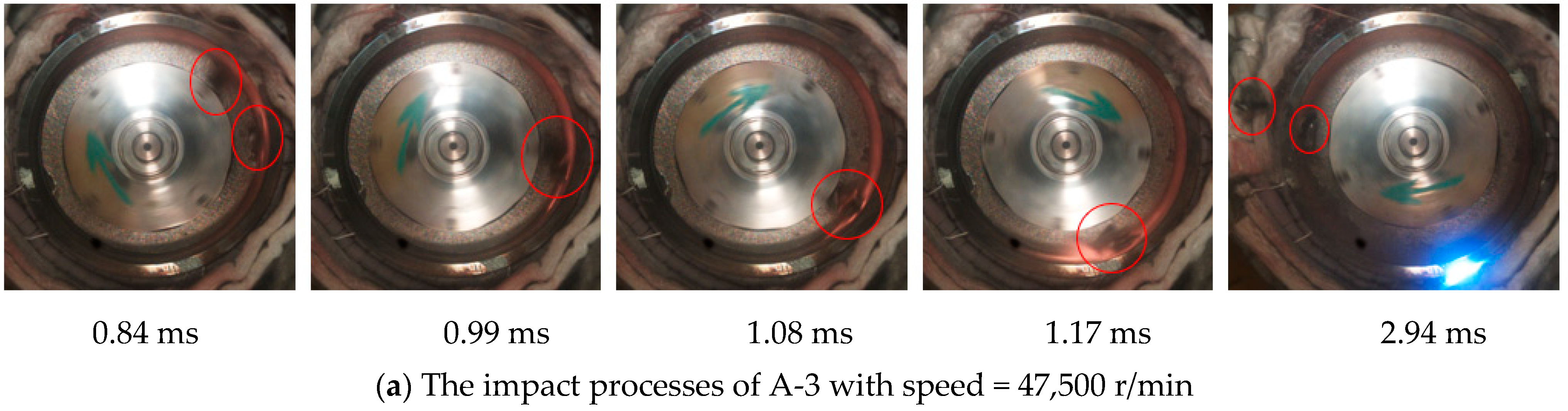
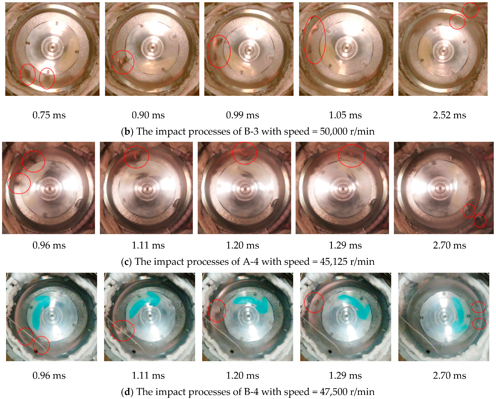
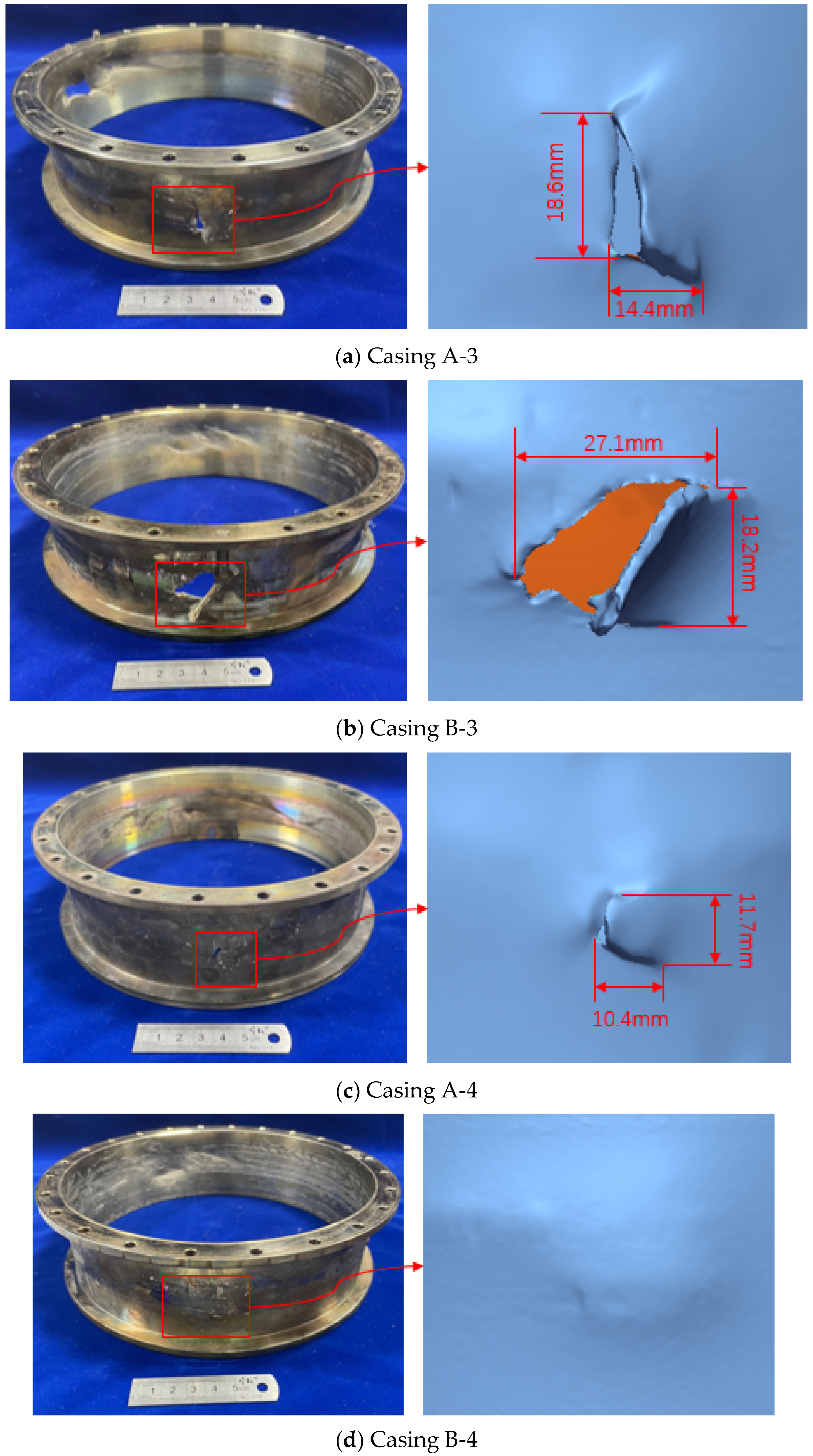
3.2.2. The Dual-Blade Containment Test Results

Figure 20 depicts high-speed photography from four dual-blade containment tests. As the process of the first blade impacting the casing is identical to that of the single-blade test, Figure 20 only shows the impact process after the second blade fractures. The process of containment for A-3 is illustrated in Figure 20a. At t = 0.99 ms, the second blade collides with the first detached blade, leading to its fracture. At t = 1.17 ms, the second blade directly impacts the casing with its root, resulting in casing damage. Subsequently, both blades slide along the inner wall of the casing. Additionally, the process of dual-blade containment tests B-3, A-4, and B-4, with gas turbine blade flying-off speeds of 50,000 r/min, 45,125 r/min, and 47,500 r/min, respectively, is essentially consistent with the aforementioned process.
In the dual-blade containment tests, the areas where the front and rear blades impact the casing are not contiguous, and the test conditions such as rotational speed are consistent between the dual-blade and single-blade tests. Therefore, the damage caused by the first blade to the casing in the dual-blade test is essentially consistent with the results of the single-blade test. This can also be observed from the simulation results in Section 2.2. Hence, Figure 21 only illustrates the damage to the casing caused by the second blade after fracturing in the dual-blade test. Additionally, localized three-dimensional scanning results of the casing are also presented. Significant breaches are observed on casings A-3, B-3, and A-4, while no breach is observed on casing B-4.

4. Discussion

4.1. Simulation and Experimentation Comparison

Damage extent and high-speed photography are used to evaluate the reliability of the simulation model. Comparing the casing damage graphs from containment tests and numerical simulation, it is evident that the numerical simulation conducted in this paper closely corresponds to the test results. Comparative analysis between the numerical simulation process and high-speed photography also reveals a close alignment in the deformation process and trajectory of the fractured blade. Figure 22 shows the blade impact process of A-1 in both the simulation and the experiment. This indicates that the numerical simulation effectively reflects the entire process of containment testing, demonstrating its applicability in engineering design.

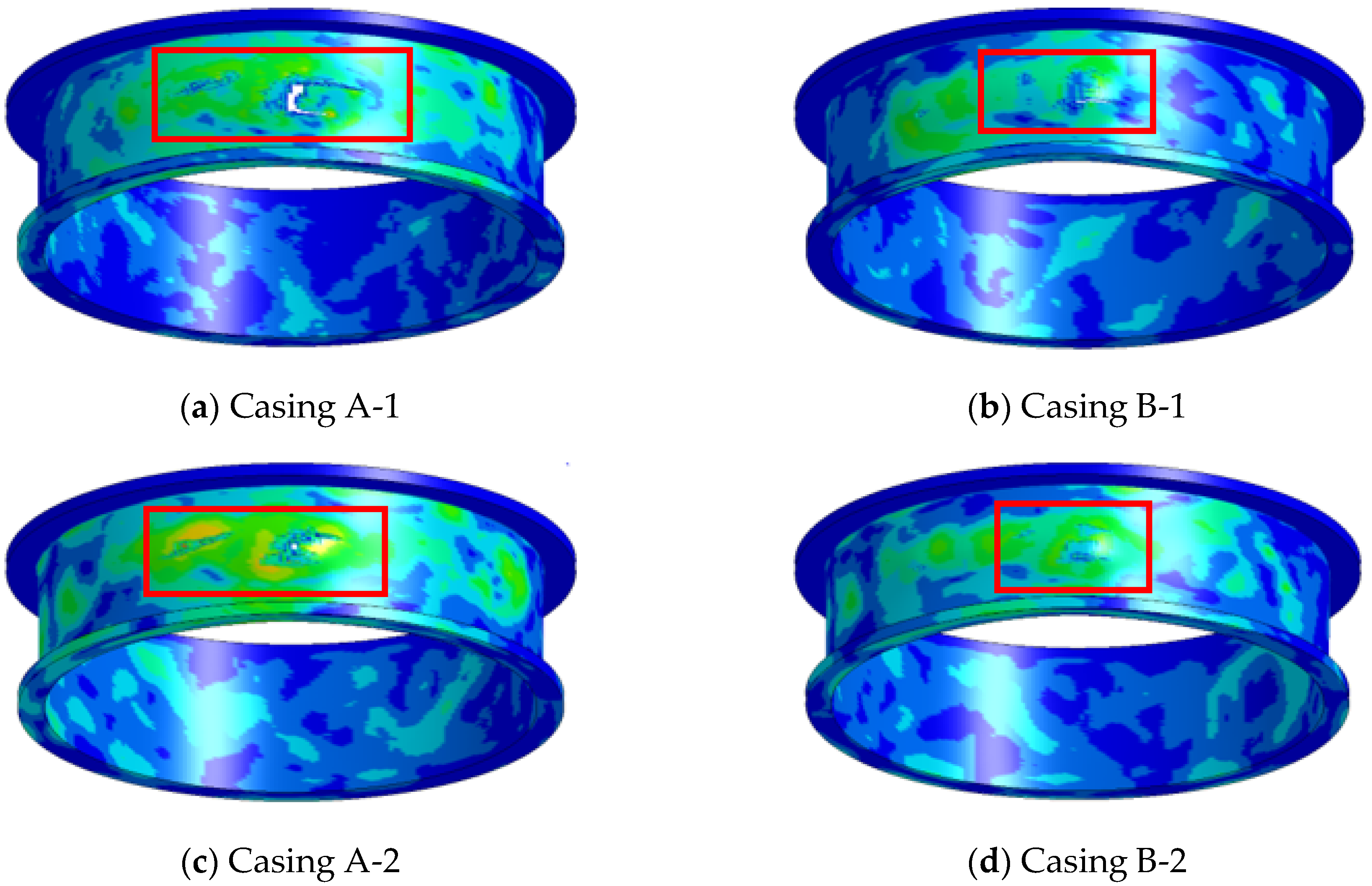
4.2. Influence of Blade Shape in Casing Containment

Figure 23 displays the containment test damage of the casings A-1 and B-1. It is evident that when the turbine blade A and B have the same detachment energy, the blade A causes significantly more damage to the casing than the blade B. The damage to the casing is primarily due to the tenon root impact. Additionally, according to the kinetic energy changes of the blades A-1 and B-1, shown in Figure 24, it can be observed that the tenon root of the blade A impacts the casing at 0.18 ms, while that of the blade B impacts at 0.21 ms. This analysis indicates that due to the longer blade body of the blade B, the interaction time between the blade body and the casing is relatively prolonged. As a result, the tenon root of the blade B impacts the casing later and with less energy compared to the blade A. Therefore, the turbine blades with longer blade body are relatively safer.

4.3. Influence of Dual-Blade Collision in Casing Containment

Meanwhile, it is observed that the damage in the dual-blade containment tests is more severe compared to the single-blade containment tests. Comparing A-2 with A-4 and B-1 with B-3, it can be inferred that when the result of the single-blade containment test indicates critical containment, the dual-blade containment experiment under the same conditions results in non-containment. This is because in the dual-blade containment test, after the second blade detaches, its root directly impacts the casing due to the influence of the first blade, resulting in a relatively higher impact energy and consequently greater damage. In contrast, in the single-blade containment test, part of the energy is consumed when the blade tip impacts the casing, resulting in relatively lower energy upon the root impact, thus leading to less severe damage. The dual-blade test indicates that the impact areas of the two blades are not directly connected, so the dual-blade containment test can be considered as a special case of single-blade detachment test. The detachment of the second blade is not due to normal rotation but caused by external impact. Meanwhile, the results of the single-blade test suggest that due to the longer blade structure of turbine blade B, it causes less damage to the casing. Therefore, it can be concluded that the damage to the casing caused by the detachment of a single blade is primarily due to the root impact, and this damage decreases as the blade length increases. And then, the detachment of a blade caused by external impact poses a higher risk.

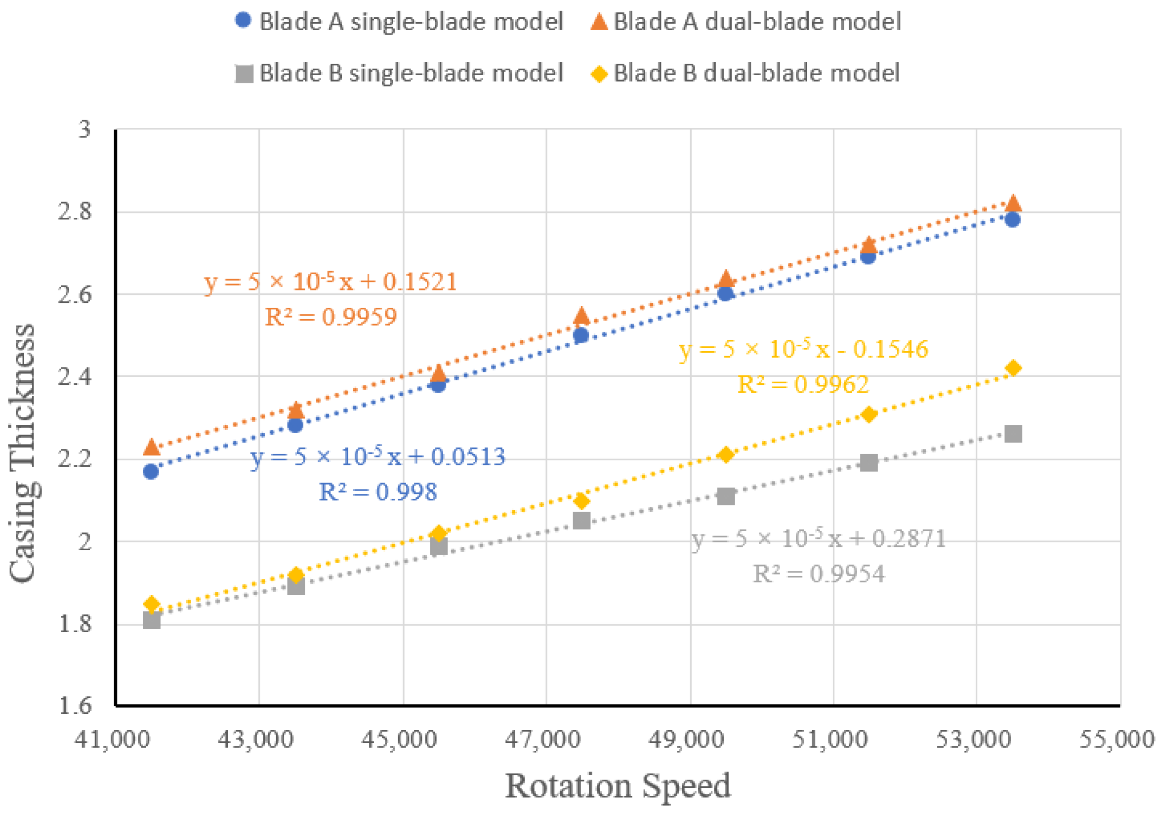
4.4. GasTurbine Single-Blade Containment Curve

Section 2 and Section 3 indicate that traditional containment coefficient methods do not yield results consistent with experiments. The containment coefficient method predicts both the gas turbine blades A and B detachment tests as containing. However, experimental results reveal that the blade A detachment test is non-containing, while the blade B detachment test is containing. Additionally, the numerical simulation results align well with experimental findings. Therefore, further investigation using finite element simulation methods to study the critical containing speeds of single-blade detachment at different thicknesses for this engine model is crucial for safety design in aviation engines, which can be used for the robust design of the casing wall thickness.
Table 3 presents the critical containment data from the simulations of single-blade and dual-blade models of the gas turbine blade A. Using an operational speed of 47,500 r/min as the median for the turbine blade A, numerical simulations were conducted for release speeds of 41,500 r/min, 43,500 r/min, 45,500 r/min, 47,500 r/min, 49,500 r/min, 51,500 r/min, and 53,500 r/min to determine the critical containment results. The critical speed of the casing is defined as the speed at which a small breach appears on the casing but no fragments are ejected from the broken blade. The impact process of blade detachment and simulation processes are similar to those described in Section 2, where the blade tip initially impacts the casing, followed by the blade flipping and the root impacting the casing, resulting in damage.
Similarly, Table 4 presents the critical containment data for the simulation of gas turbine blade B. Figure 25 illustrates the containment curves for both gas turbine blade A and B detachment scenarios. Using the containment coefficient formula as a reference, the critical speed and casing thickness data were fitted with a linear relationship. The fitted containment curves for gas turbine blades A and B both have R-squared values greater than 0.99, indicating a reasonable fit. Based on these critical containment curves, the critical detachment speed for the desired casing thickness can be determined, which is essential for the safety design of aircraft engines.
Table 3. Critical thickness of turbine blade A at different speeds.
Critical Speed (r/min)41,50043,50045,50047,50049,50051,50053,500
Casing Thinkness (mm)Single blade2.172.282.382.502.602.692.78
Dual blade2.232.322.412.552.642.722.82
Table 4. Critical thickness of turbine blade B at different speeds.
Critical Speed (r/min)41,50043,50045,50047,50049,50051,50053,500
Casing Thinkness (mm)Single blade1.811.891.992.052.112.192.26
Dual blade1.851.922.022.102.212.312.42
Figure 25. Turbine blade containment curve.
Aerospace 11 00629 g025

5. Conclusions

This paper is based on the principle of the containment coefficient method. Through combined numerical simulation analysis, the impact response process, plastic strain distribution, and casing damage caused by gas turbine blade detachment are examined. Eight corresponding experiments were conducted to verify the accuracy of the simulation results. Based on the experimental and simulation results, containment curves for gas turbine blades of this model were proposed, providing important reference for the safety design of aircraft engines. Some key conclusions of this work are summarized as follows:
(1)
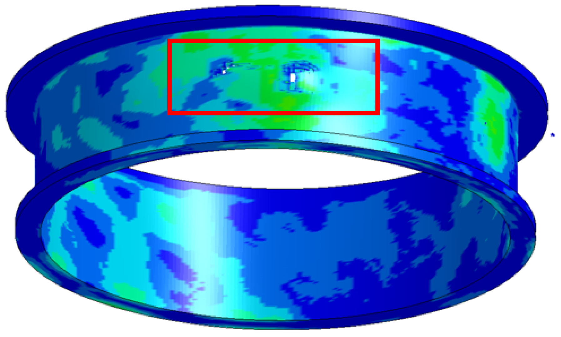
The impact response process of a single gas turbine blade detachment mainly consists of three stages: the tip of the blade hitting the casing, the root of the blade hitting the casing, and the blade sliding along the inner wall of the casing. The maximum damage to the casing is mainly caused by the impact of the blade root in the second stage.
(2)
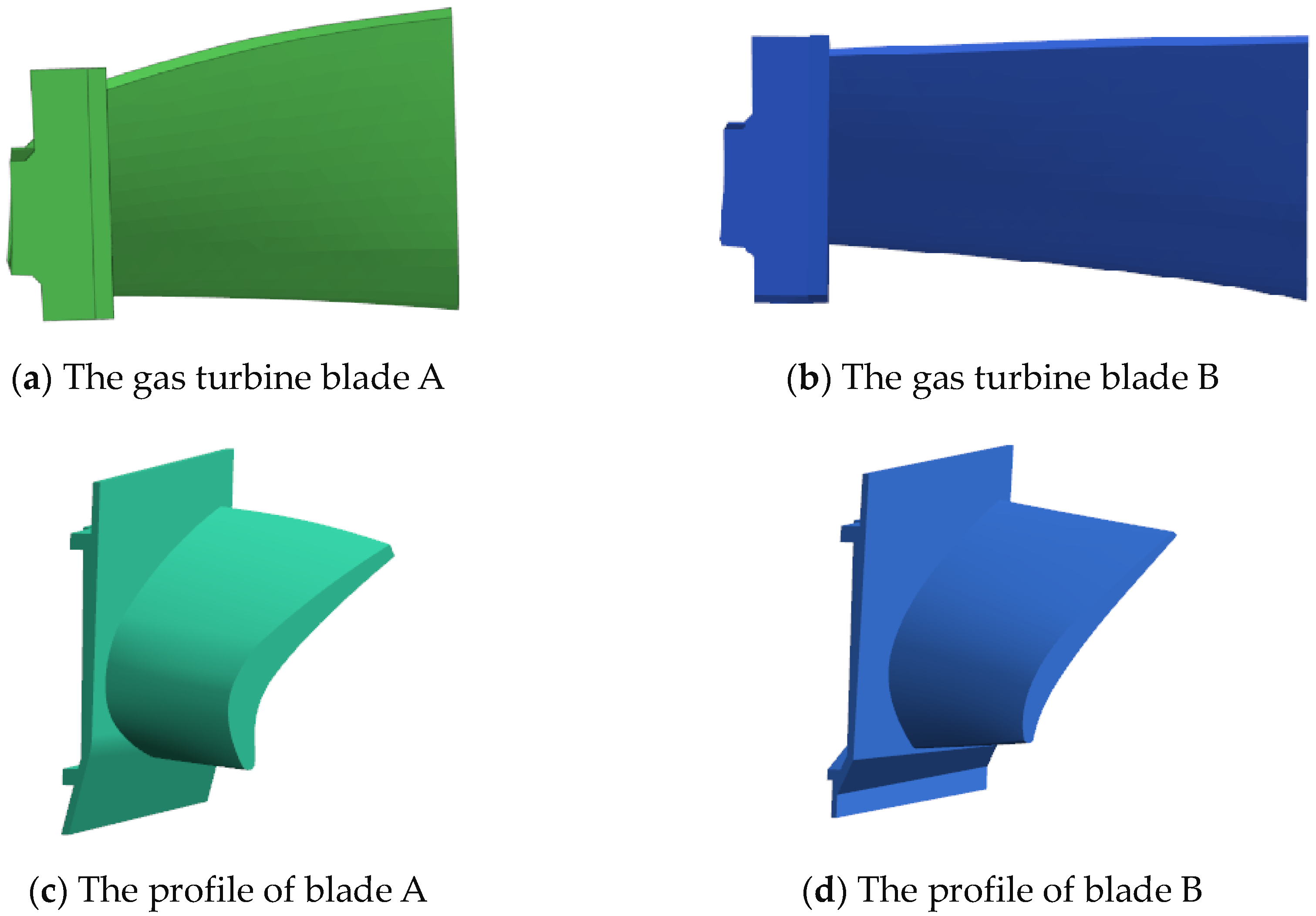
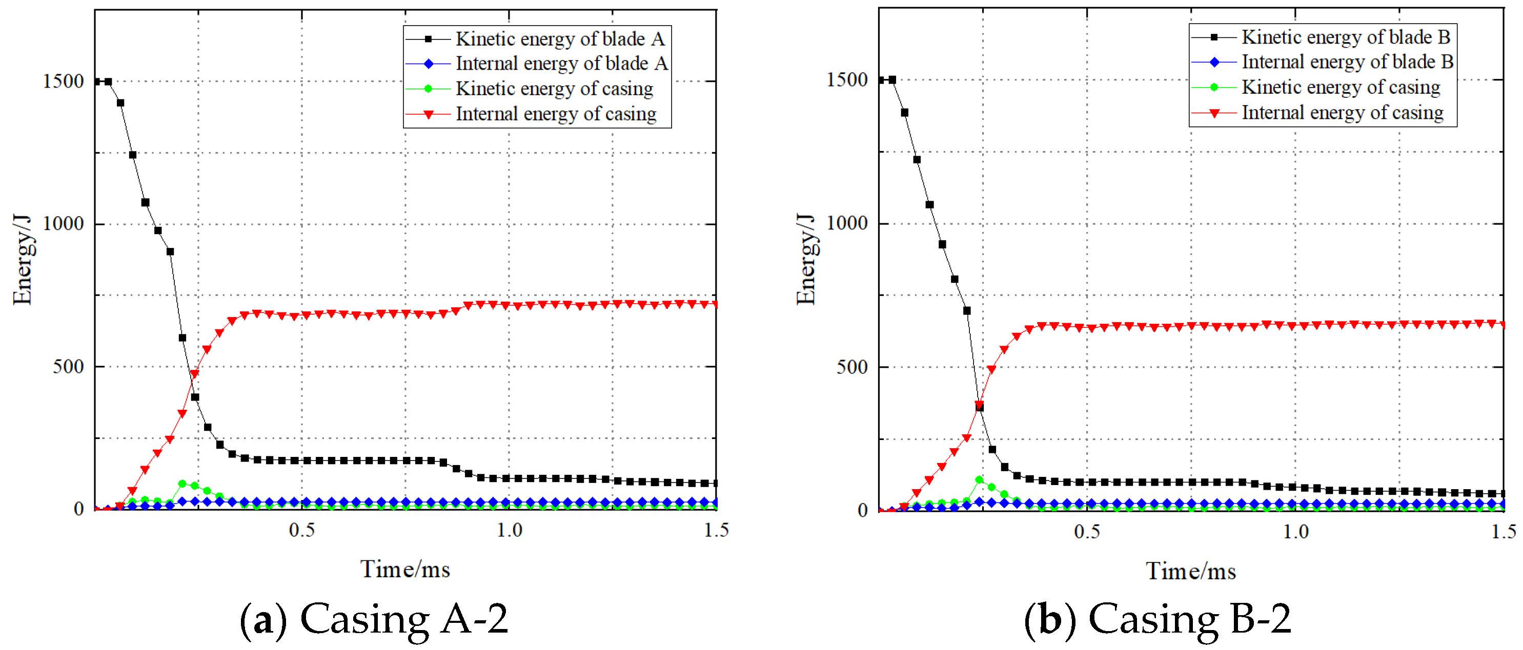
Due to the longer blade structure of the gas turbine blade B compared to the blade A, the energy of the blade root impacting the casing is relatively lower. Therefore, the safety factor of the gas turbine blade B is higher than that of the blade A.
(3)
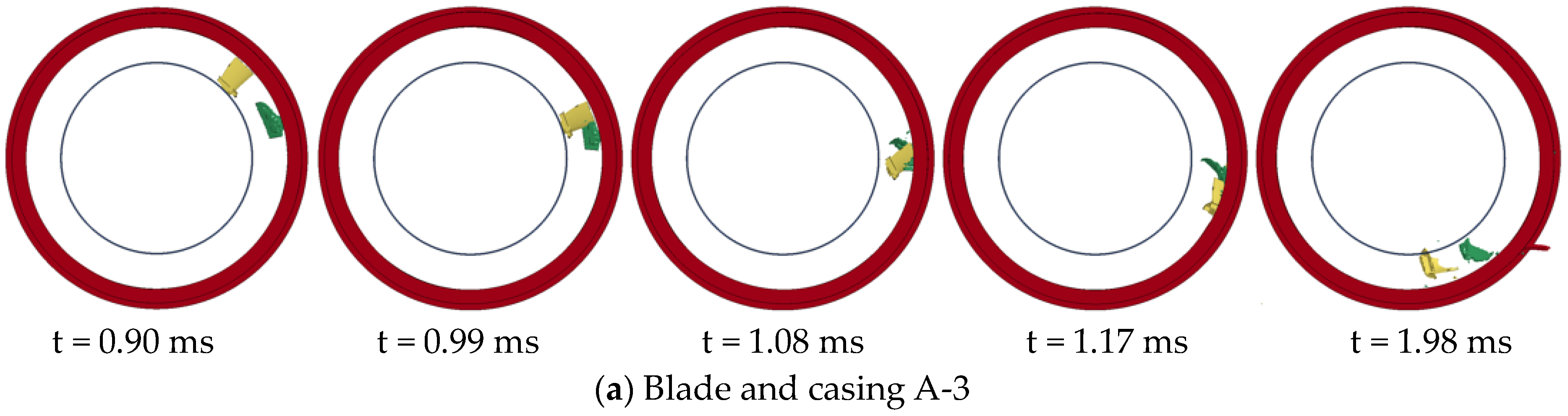
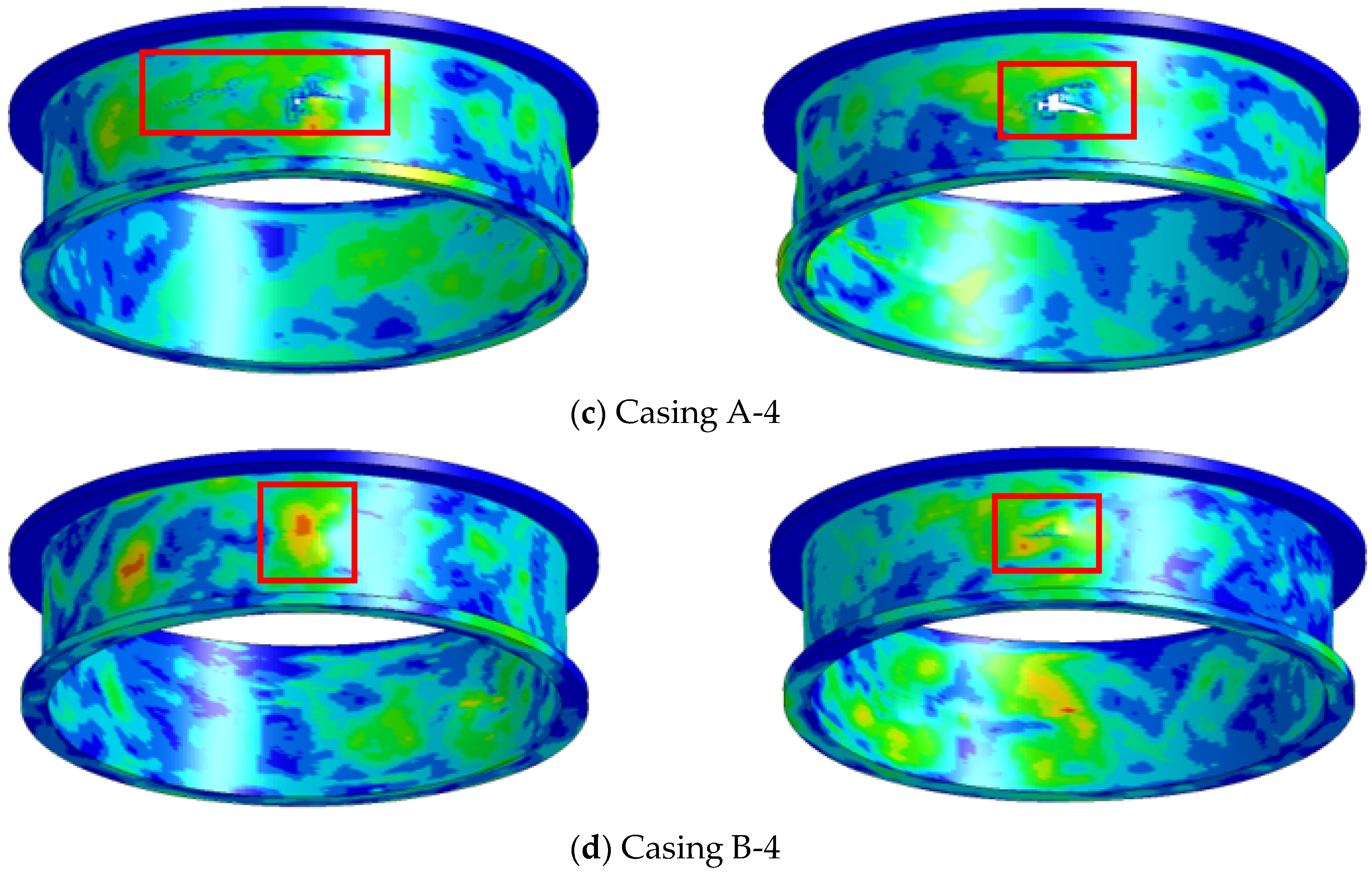
It was observed that dual-blade containment tests resulted in more severe damage compared to single-blade tests. The simulations showed that in dual-blade tests, the impact energy was higher due to the influence of the first blade, leading to larger damage. This finding highlights the critical role of interaction effects between successive blades in determining containment outcomes, shedding light on nuanced failure mechanisms critical for engine safety assessments.
(4)
Based on the numerical simulation results, curves of the containment speed for gas turbine blade detachment under different casing thicknesses are proposed. The fitting degrees of the containment curves for the blade A and B are 0.994 and 0.997, respectively. This contributes to further optimizing shell design, improving the safety and reliability of aircraft engines, and providing new ideas and methods for the development of the aviation engineering field.
Based on the work completed in this paper, we will subsequently study the mutual influence of single-blade release on adjacent blades, as well as the containment performance of the casing when different numbers of blades are released.

Author Contributions

Conceptualization, J.W. and H.X.; Methodology, M.Y., J.W. and H.X.; Software, M.Y., Z.H. and M.Q.; Validation, W.X.; Formal analysis, W.X., Z.H. and M.Q.; Investigation, M.Y. and W.X.; Data curation, Z.H.; Writing—original draft, M.Y.; Writing—review & editing, M.Y., J.W., H.X. and M.Q.; Supervision, H.X. All authors have read and agreed to the published version of the manuscript.

Funding

The research was supported by the National Science and Technology Major Projects of China (2017-IV-0006-0043).

Data Availability Statement

The original contributions presented in the study are included in the article, further inquiries can be directed to the corresponding author.

Conflicts of Interest

Author Mingmin Qu was employed by the company Zhejiang Hiro Aeronautics Technology Co., Ltd. The remaining authors declare that the research was conducted in the absence of any commercial or financial relationships that could be construed as a potential conflict of interest.

References

  1. Meher-Homji, C.B. Blading Vibration and Failures in Gas Turbines: Part B—Compressor and Turbine Airfoil Distress. In Proceedings of the ASME International Gas Turbine and Aeroengine Congress and Exposition, Houston, TX, USA, 5–8 June 1995. [Google Scholar]
  2. Australian Transport Safety Bureau; Canberra ACT. Examination of a Failed Rolls-Royce RB211-524 Turbofan Engine—Boeing Commercial Aircraft Group, 747-436, G-BNLD; Technical Analysis Rep. No. 20/02, Occurrence File No. BO/200200646; Australian Transport Safety Bureau: Canberra, Australia, 2002.
  3. Federal Aviation Administratio. Design Considerations for Minimizing Hazards Caused by Uncontained Turbine Engine and Auxiliary Power Unit Rotor Failure; FAA Advisory Circular No. 20-128A, 25 March; Federal Aviation Administration: Washington, DC, USA, 1997.
  4. Sarkar, S.; Atluri, S. Effects of multiple blade interaction on the containment of blade fragments during a rotor failure. J. Finite Elem. Anal. Des. 1996, 23, 211–223. [Google Scholar] [CrossRef]
  5. Federal Aviation Administration. Federal Aviation Administration Regulations, Part 33, Airworthiness Standards: Aircraft Engines; Federal Aviation Administration: Washington, DC, USA, 1984.
  6. MIL-STD-1783B; Engine Structural Integrity Program. Department of Defense: Washington, DC, USA, 2002.
  7. CS-E 810; Certification Specifications and Acceptable Means of Compliance for Engines: Compressor and Turbine Blade Failure. European Aviation Safety Agency: Cologne, Germany, 2015.
  8. CARR-33; Airworthiness Standards for Aircraft Engines. Civil Aviation Administration of China: Beijing, China, 2005.
  9. The Aviation Herald. Incident: Korean A333 at Seoul on 26 May 2011, Engine Shut Down in Flight Following Uncontained Failure. Available online: http://avherald.com/h?article=43da45e4&opt=0 (accessed on 4 June 2011).
  10. The Aviation Herald. Incident: Skywest CRJ7 at Chicago on 10 June 2017, Uncontained Engine Failure. Available online: http://avherald.com/h?article=4aa3ba31&opt=0 (accessed on 12 June 2017).
  11. Teng, X.; Wierzbicki, T. Gouging and fracture of engine containment structure under fragment impact. J. Aerosp. Eng. 2008, 21, 174–186. [Google Scholar] [CrossRef]
  12. Qiu, J.; Shi, J.; Su, H.; Zhang, J.; Feng, J.; Shi, Q.; Tian, X. Fatigue lifespan of engine box influenced by fan blade out. IOP Conf. Ser. Mater. Sci. Eng. 2017, 265, 012026. [Google Scholar] [CrossRef]
  13. He, Z.; Guo, X.; Xuan, H.; Shan, X.; Fan, X.; Chen, C.; Hong, W. Characteristics and Mechanisms of Turboshaft Engine Axial Compressor Casing Containment. Chin. J. Aeronaut. 2021, 34, 171–180. [Google Scholar] [CrossRef]
  14. Jiang, X.; Liu, S.; Li, S. Analysis of engine containment test method of turbofan engine with high by-pass ratio. J. Aeroengine 2021, 47, 60–63. [Google Scholar]
  15. Xuan, H.; Hu, Y.; Wu, Y.; He, Z. Containment Ability of Kevlar 49 Composite Case under Spinning Impact. J. Aerosp. Eng. 2018, 31, 04017096. [Google Scholar] [CrossRef]
  16. He, Z.; Xuan, H.; Bai, C. Containment of soft wall casing wrapped with Kevlar fabric. Chin. J. Aeronaut. 2019, 32, 954–966. [Google Scholar] [CrossRef]
  17. Bai, C.; Xuan, H.; Huang, X. Containment ability and groove depth design of U type protection ring. Chin. J. Aeronaut. 2016, 29, 395–402. [Google Scholar] [CrossRef]
  18. Sengoz, K.; Kan, S.; Eskandarian, A. Development of a Generic Gas-Turbine Engine Fan Blade-Out Full-Fan Rig Model; The George Washington FHWA/NHTSA National Crash Analysis Center: Washington, DC, USA, 2015.
  19. Tuninetti, V.; Sepúlveda, H. Computational Mechanics for Turbofan Engine Blade Containment Testing: Fan Case Design and Blade Impact Dynamics by Finite Element Simulations. Aerospace 2024, 11, 333. [Google Scholar] [CrossRef]
  20. Yang, S.; Chen, C.; Liu, G. An Experimental and Simulation Study of Impact Resistance in Sandwich Structures Casing. Proc. Inst. Mech. Eng. Part G J. Aerosp. Eng. 2019, 233, 3635–3648. [Google Scholar] [CrossRef]
  21. He, Q.; Xie, Z.; Xuan, H. Multi-blade effects on aero-engine blade containment. J. Aerosp. Sci. Technol. 2016, 49, 101–111. [Google Scholar] [CrossRef]
  22. Sinha, S.K.; Dorbala, S. Dynamic loads in the fan containment structure of a turbofan engine. J. Aerosp. Eng. 2009, 22, 260–269. [Google Scholar] [CrossRef]
  23. Eryilmaz, I.; Guenchi, B.; Pachidis, V. Multi-blade shedding in turbines with different casing and blade tip architectures. J. Aerosp. Sci. Technol. 2019, 87, 300–310. [Google Scholar] [CrossRef]
  24. VanderKlok, A.; Stamm, A.; Xiao, X. Fan-blade-out experiment at small scale. J. Exp. Tech. 2016, 40, 1479–1484. [Google Scholar] [CrossRef]
  25. Kraus, A.; Frischbier, J. Containment and penetration simulation in case of blade loss in a low pressure turbine. In DYNAmore LS-DYNA Forum; DYNAmore GmbH: Stuttgart, Germany, 2002. [Google Scholar]
  26. Roy, P.A.; Meguid, S.A. Containment and arrest of blade shedding in gas turbine engines using novel dual-ring design. J. Eng. Gas Turbines Power 2021, 143, 071015. [Google Scholar] [CrossRef]
  27. International Aviation Editorial Board. Stress Standards for the Spey MK202 Engine (EGD-3); International Aviation Editorial Board: London, UK, 1979. [Google Scholar]
  28. Johnson, G.R.; Cook, W.H. A constitutive model and data for metals subjected to large strains, high rates and high temperatures. In Proceedings of the 7th International Symposium on Ballistics, The Hague, The Netherlands, 19–21 April 1983; pp. 541–547. [Google Scholar]
  29. Johnson, G.R.; Cook, W.H. Fracture characteristics of three metals subjected to various strains, strain rates, temperatures and pressures. Eng. Fract. Mech. 1985, 21, 31–48. [Google Scholar] [CrossRef]
  30. Chen, L.; Xuan, H.; Jia, W.; Liu, J.; Fang, Z.; Zheng, Y. Neck Structure Optimal Design of the Turbine Wheel for Containment Design of the Air Turbine Starter. Aerospace 2023, 10, 802. [Google Scholar] [CrossRef]
  31. Fan, X. Simulation and Structural Optimization Study of Containment Ring Containment Capability with U-Shaped Section. Master’s Thesis, Zhejiang University, Hangzhou, China, 2021. [Google Scholar]
Figure 1. Non-containment incident in the GECF34 engine turbine casing.
Aerospace 11 00629 g001
Figure 2. The gas turbine blades A and B.
Aerospace 11 00629 g002
Figure 3. Schematic diagram of the casing model.
Aerospace 11 00629 g003
Figure 4. FEM model.
Aerospace 11 00629 g004
Figure 9. Process of the turbine blade pieces impacting the casings A-2 and B-2.
Aerospace 11 00629 g009
Figure 10. Energy changes in the containment process.
Aerospace 11 00629 g010
Figure 11. The single-blade casing damage.
Aerospace 11 00629 g011
Figure 12. The A-2* FEM model.
Aerospace 11 00629 g012
Figure 13. The A-2* casing damage.
Aerospace 11 00629 g013
Figure 14. Process of the turbine blade pieces impacting the dual-blade model casings.
Aerospace 11 00629 g014aAerospace 11 00629 g014b
Figure 15. The dual-blade casing damage.
Aerospace 11 00629 g015aAerospace 11 00629 g015b
Figure 16. Schematic diagram of the test structure.
Aerospace 11 00629 g016
Figure 17. Containment test setup diagram.
Aerospace 11 00629 g017
Figure 19. Damage condition of four single-blade containment tests.
Aerospace 11 00629 g019aAerospace 11 00629 g019b
Figure 20. High-speed photography of the dual-blade containment test.
Aerospace 11 00629 g020aAerospace 11 00629 g020b
Figure 21. Damage condition of four dual-blade containment tests.
Aerospace 11 00629 g021
Figure 22. The comparison of the blade impact process between simulation and experiment.
Aerospace 11 00629 g022
Figure 23. The comparison of casing damage between A-1 and B-1.
Aerospace 11 00629 g023
Figure 24. The kinetic energy changes during the impacts A-1 and B-1.
Aerospace 11 00629 g024
Table 1. J-C model material parameters of gas turbine casing and blades.
MaterialJ-C Constitutive Model Parameters
A/MPaB/MPanCM
GH416987210840.5450.01341.3
K41785010900.650.0141.1
MaterialJ-C Failure Model Parameters
D1D2D3D4D5
GH41690.110.241.922.12 × 10−50.65
K417−0.10.240.450.0113.84
Table 2. The finite element simulation results.
Simulation
ID
Simulation ModelThickness
(mm)
Spin Speed
(r/min)
Results
A-1Single-blade model2.3747,500Non-containment
B-12.1250,000Critical containment
A-22.3745,125Critical containment
B-22.1247,500Containment
A-3Dual-blade model2.3747,500Non-containment
B-32.1250,000Non-containment
A-42.3745,125Non-containment
B-42.1247,500Containment
Disclaimer/Publisher’s Note: The statements, opinions and data contained in all publications are solely those of the individual author(s) and contributor(s) and not of MDPI and/or the editor(s). MDPI and/or the editor(s) disclaim responsibility for any injury to people or property resulting from any ideas, methods, instructions or products referred to in the content.

