Article

Integrated Design and Simulation of Helicopter Nuclear, Biological, and Chemical Protection System

1
School of Aero-Engine, Shenyang Aerospace University, Shenyang 110136, China
2
School of Aeronautic Science and Engineering, Beijing University of Aeronautics and Astronautics, Beijing 100191, China
*
Author to whom correspondence should be addressed.
Aerospace 2024, 11(8), 633; https://doi.org/10.3390/aerospace11080633
Submission received: 8 June 2024 / Revised: 30 July 2024 / Accepted: 31 July 2024 / Published: 1 August 2024

Abstract

:
The helicopter’s aircrew faces significant challenges in nuclear, biological, and chemical (NBC) environments due to limited protection devices and crowded space. To safeguard the security and ensure the comfort of the aircrew, the development of a helicopter NBC protection system is crucial. In this study, a helicopter NBC protection system was designed using a top-level architecture with an advanced system-integrated approach. Detailed configuration designs were developed for each subsystem, including air source pressurization, renewable NBC filtration ventilation, cabin temperature, and pressure control system. To verify the reliability of the adsorbent model, a Langmuir isotherm equation was adapted and validated using the experiment data. To verify the performance of the designed system, a dynamic simulation model was created using AMESIM. The findings demonstrate that the cabin temperature and pressure control system can greatly satisfy the demand for aircrews under various working conditions. Furthermore, the renewable NBC filtration ventilation system effectively adsorbs NBC substances and achieves onboard regeneration, thereby extending the working lifespan in contaminated environments. This study contributes to providing an innovative idea for helicopter NBC protection systems.

1. Introduction

The helicopter’s capacity to enter and exit the battlefield quickly, along with its combat and rescue, plays a crucial role in national aviation power [1,2,3]. However, in a nuclear, biological, and chemical (NBC) environment, the aircrew will be harmed both in the body and psychology due to helicopter exposure to an external contaminated environment.
In order to address these difficulties, certain countries have proposed various solutions, including the C4 chemical protective mask and head cover system developed by Canada for the “Sea King” helicopter, the NBC/F protective cover developed by France, and the M24 gas mask initially equipped by the U.S. Air Force, which was later upgraded to the M43 and M43E1 gas masks [4]. The лп-3-120 gas mask was developed by Russia [5], and the AR5 anti-gas equipment was developed by UK [6].
The respiratory masks used by pilots offer protection to the face, throat, and respiratory system against NBC discharges. However, due to the confined space and crowded personnel within helicopters, individual protective equipment not only hinders aircrew actions but also experiences a significant reduction in its protective efficacy over time [7,8]. Consequently, there is an urgent necessity to introduce a more proactive and efficient measure for protecting helicopters operating in contaminated areas.
The collective protection system (CPS) is a primary system configuration that effectively shields against NBC agents by integrating filtration equipment with air conditioning ventilation equipment in a centralized area [9]. Research on CPS commenced in the mid-1960s, with German scientists pioneering the initial investigations in this field [10]. Currently, the focus of research and application of CPS is primarily on surface ships and vehicles. In 1970, Germany spearheaded research on the NBC collective protection system for ships, leading to the development of the Dauer Schultzluft Klime (DSK) system. Subsequently, the UK also embarked on related research and introduced the CITADEL system. The United States incorporated advantages from both German and British systems, resulting in widespread utilization of the CPS [11].
Research on vehicle-based protection systems commenced in the mid-20th century, with the former Soviet Union pioneering the integration of NBC protection systems into vehicles and developing more than ten protective vehicles. By the early 1980s, Germany had successfully developed its own NBC warfare vehicles that exhibited comparable protective capabilities to the advanced БРДM2-PX6 from the Soviet Union during that period. France has also innovatively designed an NBC armored vehicle based on the VAB4 × 4 platform, specifically tailored for effective operation in environments contaminated with NBC substances. Moreover, this vehicle is equipped with detection capabilities to accurately identify various types and concentrations of pollutant gases present in such environments.
Within the collective protection system, NBC filtration technology is deemed essential for its successful deployment [12]. The activated carbon used to be an adsorbent for CPS due to its characteristics of adsorbing radioactive dust, biochemical aerosols, and toxic vapors [13,14,15]. However, these systems often exhibit a limited operational lifespan and necessitate the frequent replacement of filters.
In recent years, numerous countries have conducted extensive research on the application of pressure swing adsorption (PSA) and temperature swing adsorption (TSA), driven by advancements in renewable adsorption technology. These developments have enabled CPS to achieve the recycling of adsorption/desorption processes, thereby significantly prolonging their operational lifespan. Considering the research on renewable adsorption systems, G. Swetha et al. [16] established a renewable adsorption system that employed a 13X molecular sieve as the adsorbent for air purification in the presence of dimethyl methyl phosphonate (DMMP). The results demonstrated the efficacy of the 13X molecular sieve in adsorbing DMMP. Rogan Carr et al. [17] conducted a comprehensive investigation into the adsorption isotherm of DMMP, offering a standardized description of the coefficient α in the adsorption isotherm equation. Furthermore, Waheed et al. [18] examined the adsorption performance of various adsorbents for DMMP using pressure swing adsorption, with the findings indicating that the 13X molecular sieve exhibited the highest adsorption capacity for DMMP. The U.S. Department of Defense employed pressure swing adsorption technology developed by PALL Company to assess different toxins within the NBC defense program. This application served to validate the feasibility of utilizing pressure swing adsorption technology in the realm of NBC filtration [19].
In this paper, a helicopter NBC protection system is designed by using a reasonable system integration method. The detailed configuration of each subsystem is designed based on the air source pressurization system, renewable NBC filtration ventilation system, cabin temperature control system, and cabin pressure control system. According to the designed system configuration, a mathematical model of the main components and a simulation model of the system are established. The dynamic performance of the system is evaluated through simulation calculations, and its performance under various conditions is validated.

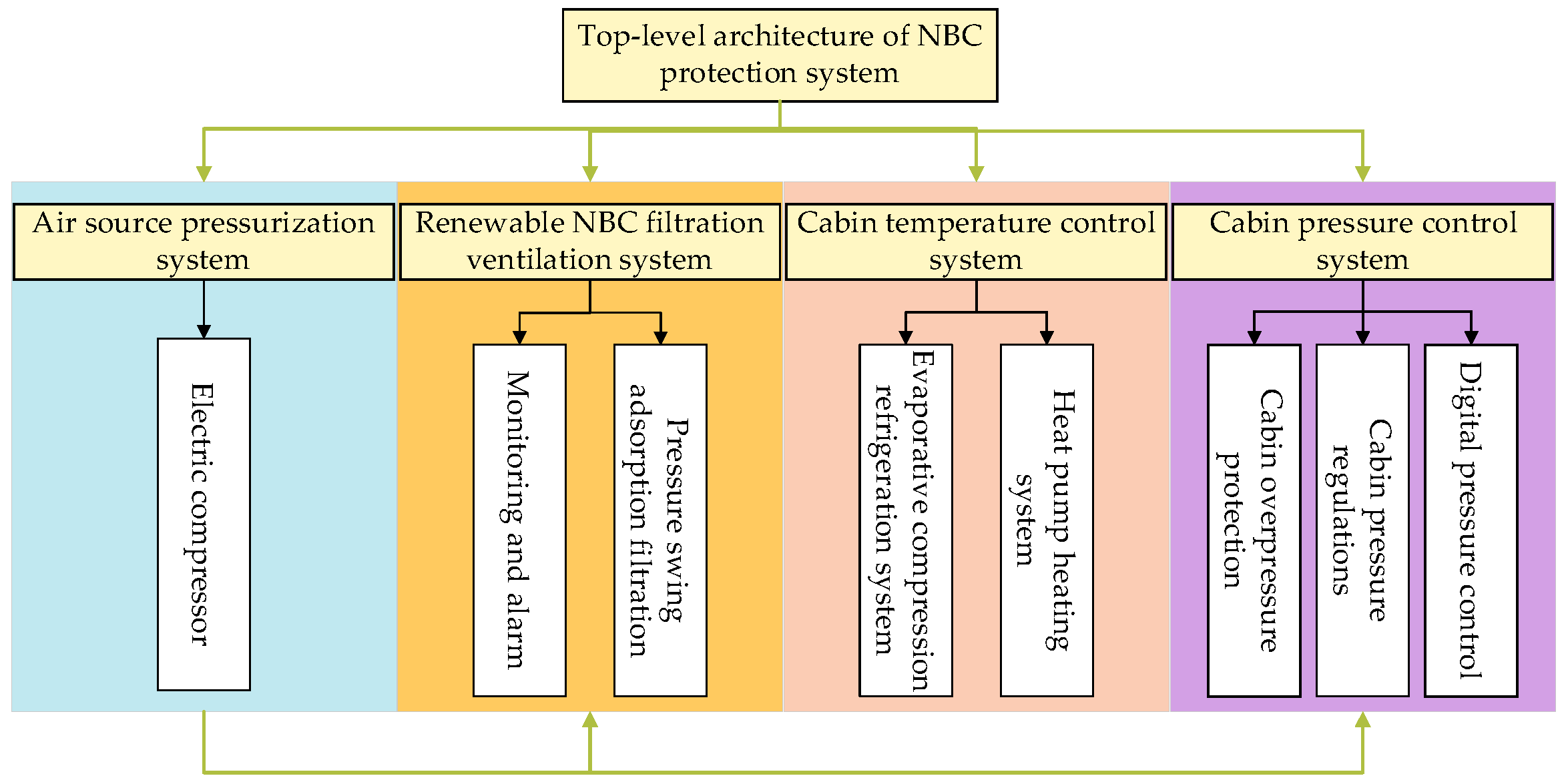
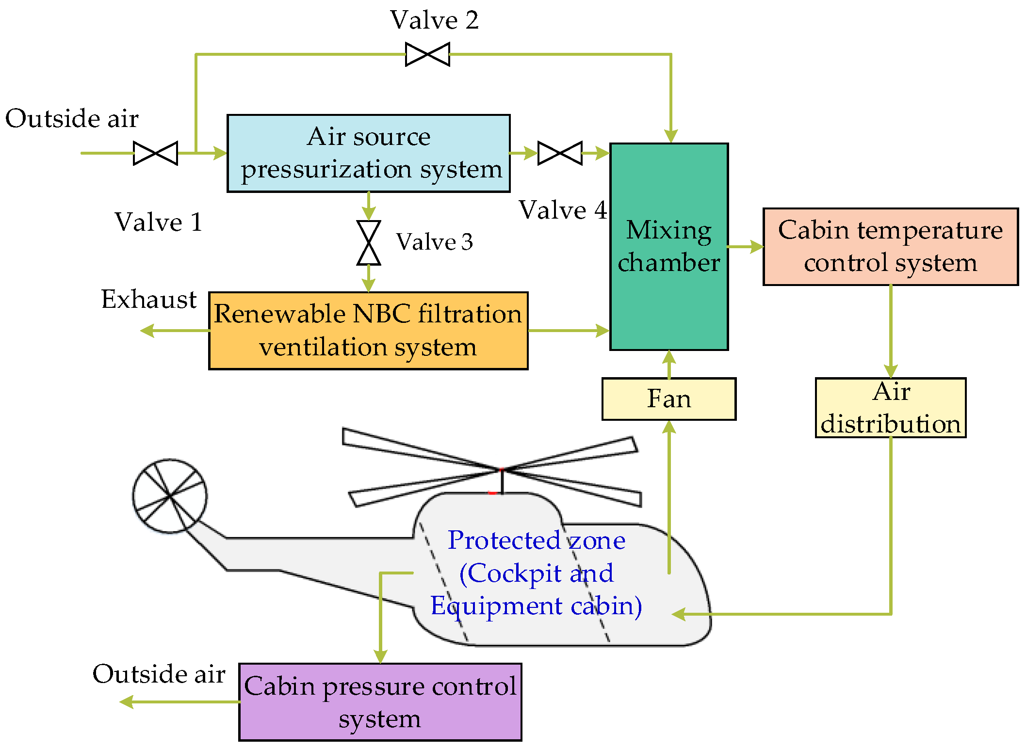
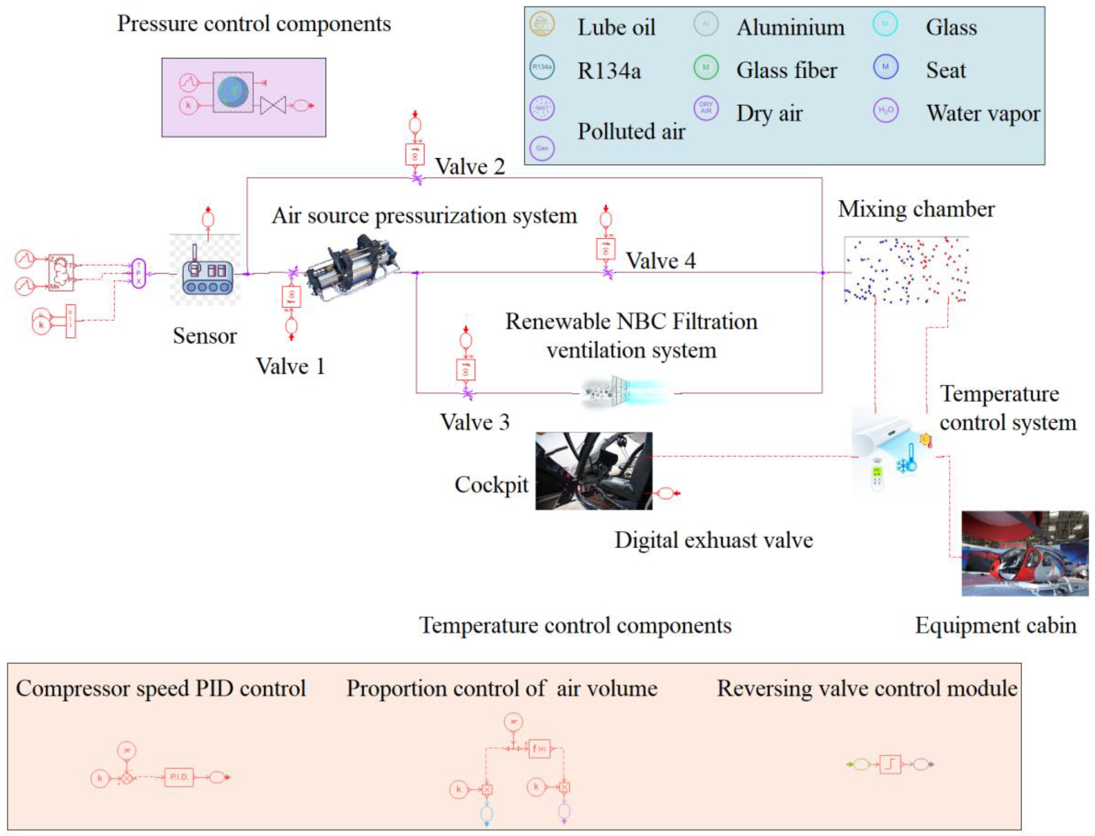
2. The Top-Level Architecture of the System

Currently, there is no established NBC protection system for helicopters, and the CPS used in ships cannot be effectively applied to helicopters. Consequently, NBC protection for helicopters primarily relies on individual protective measures. To address this gap in helicopter NBC protection, this paper proposes a top-level architecture-based system integration approach to design a comprehensive helicopter NBC protection system. The functional modules of the system are shown in Figure 1. The system comprises four subsystems: an air source pressurization system, a renewable NBC filtration ventilation system, a cabin temperature control system, and a cabin pressure control system. Although each subsystem adopts a modular design, they are not completely independent of one another. Through systematic integration, function matching and working mode switching can be achieved.
The overall architectural design and operational process of the system are shown in Figure 2. By manipulating the opening and closing of valves 1 and 2, switching between the air source pressurization mode and free ventilation mode can be achieved. The utilization of the free ventilation mode is restricted to situations where there is no requirement to activate the NBC protection of the cabin. On the other hand, the air source pressurization mode not only facilitates cabin pressurization but also ensures overpressure safeguarding.
Through the opening and closing of valves 3 and 4, the transition between the renewable NBC filtration ventilation mode and the air source pressurization mode can be achieved. In the air source pressurization mode, valve 3 is closed, while valve 4 is opened. Pressurized fresh air enters the mixing chamber, where it combines with return air before entering the cabin temperature control system for refrigeration or heating purposes. Finally, regulated air is distributed to both the cockpit and electronic equipment cabin. When an NBC agent in the atmospheric environment is detected by the monitoring unit, the overpressure protection mode is immediately activated. At the same time, valve 4 closes while valve 3 opens. The air undergoes purification via a renewable NBC filtration ventilation system before entering the cabin temperature control system through the mixing chamber for temperature regulation purposes. Ultimately, the regulated air is distributed to the designated protection areas.

3. Subsystem Design

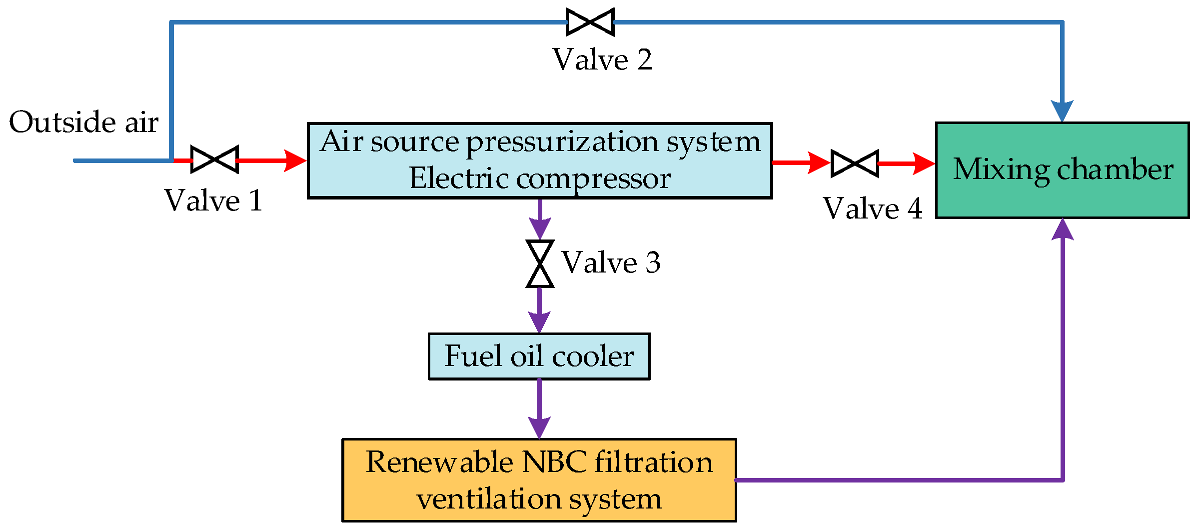
3.1. Air Source Pressurization System

The air source pressurization system can provide a continuous supply of high-pressure air for other subsystems, meeting the needs of cabin overpressure protection and pressure swing adsorption (PSA) of the renewable NBC filtration ventilation system. The configuration of the air source pressurization system is shown in Figure 3. The presented system is composed of an electric compressor, a fuel cooler, and valves.
In the free ventilation mode, the electric compressor is not required to operate, and the system workflow is shown by the blue line in Figure 3. At the same time, only valve 2 remains open, allowing outside air to enter the mixing chamber directly. In the air source pressurization mode, the system workflow is shown by the red line in Figure 3. Valves 1 and 4 are opened, while valves 2 and 3 are closed during this phase. The outside air undergoes pressurization from the electric compressor before flowing into the mixing chamber.
In the renewable NBC filtration ventilation mode, the system workflow is shown by the purple line in Figure 3. Valves 1 and 3 are open, while valves 2 and 4 are closed. The outside NBC air undergoes pressurization by the electric compressor before entering the fuel cooler, where its temperature is lowered to meet the filtration requirements. Subsequently, it flows into the renewable NBC filtration ventilation system.

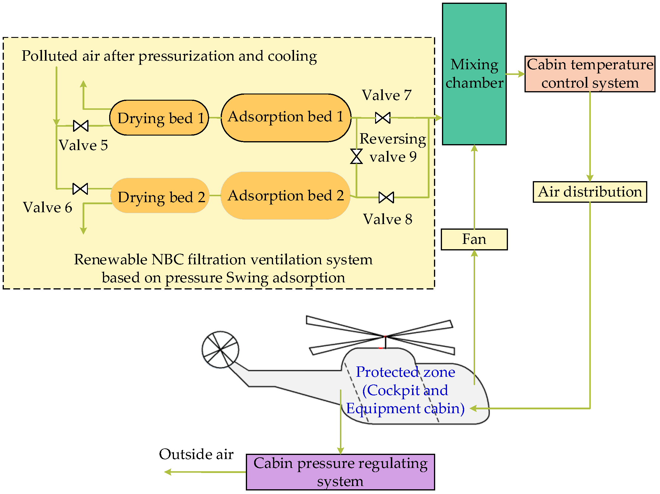
3.2. Renewable NBC Filtration Ventilation System

Traditional CPS commonly utilizes activated carbon for the adsorption of radioactive dust, biochemical aerosols, or toxic vapors. However, these systems have a limited operational lifespan and necessitate frequent filter replacement. Hence, this paper proposes a renewable NBC filtration ventilation system based on PSA that enables helicopters to undertake prolonged missions in contaminated areas. The system configuration is shown in Figure 4.
The system is mainly composed of a drying bed, adsorption bed, and valves. Silica gel serves as the drying medium in the drying bed, while a 13X molecular sieve acts as the adsorbent in the adsorption bed. The adsorption process adopts a dual-bed cycle method. Polluted air flows into drying bed 1 through valve 5 to eliminate water content and subsequently flows into adsorption bed 1 for NBC pollutant absorption. Finally, clean air is divided into two streams: most of it passes through valve 7 into the mixing chamber for subsequent treatment, while a small portion is depressurized via reversing valve 9 before being blown into adsorption bed 2 to desorb at atmospheric pressure. After desorption, the polluted air undergoes further drying by drying bed 2 before being directly discharged into the atmospheric environment.
When adsorption bed 1 reaches saturation, valve 5 is closed, and valve 6 is opened. The contaminated air passes through drying bed 2 and adsorption bed 2, creating two separate flow paths. The majority of the air enters the mixing chamber via valve 8 for subsequent treatment. A small portion of the air is depressurized through reversing valve 9 before being blown into adsorption bed 1, where it undergoes drying by drying bed 2, and is then discharged into the atmospheric environment. This cyclic process allows the real-time regeneration of clean airborne air and ensures a continuous and uninterrupted ventilation process.

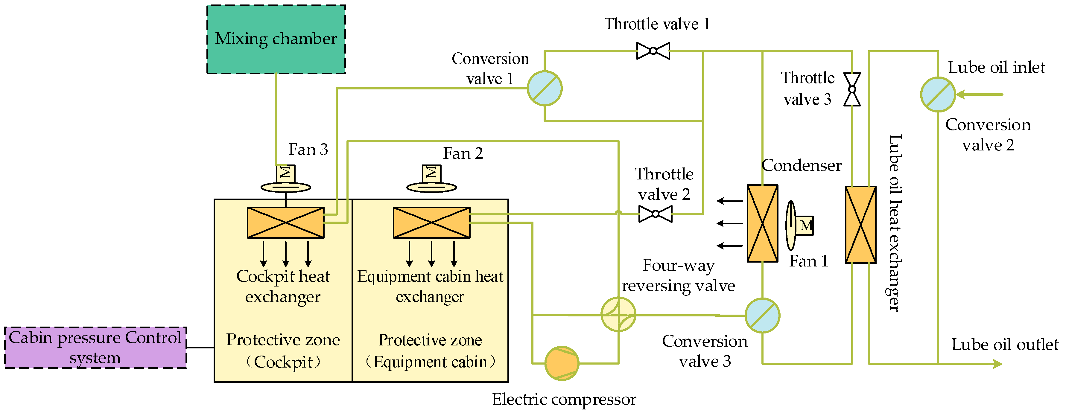
3.3. Cabin Temperature Control System

The cabin temperature control system is utilized to regulate the temperature of both the cockpit and equipment cabin, ensuring optimal operational conditions for the helicopter’s aircrew and equipment in various atmospheric environments. In this paper, a cabin temperature control system that utilizes a heat pump evaporative refrigeration cycle, waste heat recovery from lube oil, and comprehensive temperature control technology for two cabins is proposed. The system configuration is shown in Figure 5.
Clean air, which has undergone a heat transfer process in the cockpit heat exchanger, is directed to the cockpit for either cooling or heating purposes. On the other hand, the electronic equipment cabin relies on internal circulation facilitated by a fan instead of a fresh air supply. The heat exchanger in the equipment cabin is utilized to dissipate heat and maintain a cool temperature.
In the refrigeration mode, the high-pressure working fluid at the outlet of the electric compressor passes through both the four-way reversing valve and conversion valve 3 before flowing into the condenser for cooling. The cooled working fluid is then divided into two streams: one stream passes through throttle valve 1 and conversion valve 1 to cool down the cockpit in the cockpit heat exchanger, while another stream flows through throttle valve 2 to reach the equipment cabin’s heat exchanger. After undergoing heat transfer, this second stream also enters back into the electric compressor, thus completing the entire refrigeration cycle. It should be noted that lube oil exits via a separate branch controlled by conversion valve 2 and does not participate in any heat transfer process.
In the heating mode, the high-pressure working fluid at the outlet of the electric compressor flows into the cockpit heat exchanger through the four-way reversing valve for cockpit heating. The working fluid at the outlet of the cockpit heat exchanger is divided into two streams after passing through conversion valve 1. One stream passes through throttle valve 2, evaporates and absorbs heat in the heat exchanger of the equipment cabin, and then directly returns to the electric compressor as heated working fluid, while the other stream flows through throttle valve 3 and enters the lube oil heat exchanger to exchange heat with lube oil that has passed through conversion valve 2. The heated working fluid then passes through conversion valve 3 and the four-way reversing valve before finally returning to flow into the electric compressor, thus completing the full cycle of the heat pump system. The lube oil exits from a separate branch.

3.4. Cabin Pressure Control System

The digital cabin pressure control system for the helicopter primarily consists of a cabin pressure controller, digital exhaust valve, cabin pressure regulations, and a selection and display panel. The cabin pressure controller serves as a pivotal component in achieving precise control over the cabin pressure within this system.
The helicopter cabin pressure control system transmits real-time cabin pressure, helicopter flight data, cabin pressure regulations, and pilot operation signals to the cabin pressure controller. The feedback signals are analyzed by the cabin pressure controller to calculate the deviation between the real-time cabin pressure and the target pressure according to the cabin pressure regulations. Subsequently, instructions are issued to regulate the opening of the exhaust valve and modify the exhaust flow in accordance with the updated target pressure based on cabin pressure regulations. This ensures effective control of helicopter cabin pressurization. The system configuration is shown in Figure 6.

4. Mathematical Model

In this section, the mathematical models for the principal components of each subsystem, as proposed in Section 3, are established, including the compressor, fuel oil cooler, adsorption bed, two-phase heat exchanger, and throttle valve.

4.1. Air Source Pressurization System

4.1.1. Compressor

The pressure ratio, as an important parameter index of the compressor, is the ratio of the outlet flow pressure to the inlet flow pressure of the compressor, which is given as
π c = P Cdown P Cup
where πc is the compressor pressure ratio; PCup and PCdown are the pressure of the inlet flow and the outlet flow of the compressor, respectively, Pa.
The outlet airflow temperature of the compressor can be calculated as
T Cdown = T Cup · 1 + 1 η is · π c γ 1 γ 1
where TCup and TCdown are the temperature of the inlet flow and the outlet flow of the compressor, respectively, K; ηis is the adiabatic efficiency of the compressor, and γ is the specific heat ratio of the air, which is calculated as
γ = T Cup T Cdoor γ ( T ) d T T Cdownn T Cup
The power, compressor consumed can be calculated by
W comp = m ac · ( h out h in )
where mac is the actual mass flow of air, kg/s; and hin and hout are the specific enthalpy of the compressor inlet and outlet flow, respectively, J/kg.

4.1.2. Fuel Oil Cooler

In this paper, a plate-fin heat exchanger is mainly used, and the ε-NTU method can be applied to calculate its heat exchange amount [20].
Q oil , 1 = Q oil , 2 = ε Q max
where Qoil,1 is the heat exchange between the hot fluid and the fuel cooler, W; Qoil,2 is the heat exchange between the cold fluid and the fuel cooler, W; and ε and Qmax are the thermal efficiency and maximum heat transfer amount of the fuel cooler, respectively.
Q max = m i n ( C a , C b ) ( T in , 1 T in , 2 )
ε = 1 e x p N T U 1 C 1 C exp N T U 1 C
where Ca and Cb are the heat capacities of the hot fluid and cold fluid, respectively, W/K; Tin,1 and Tin,2 are the inlet temperatures of the hot fluid and cold fluid in the fuel cooler, respectively, K; C* is the heat capacity ratio of the fluid in the fuel cooler; NTU is a dimensionless number, defined as
N T U = U A m i n ( C a , C b )
1 U A = 1 η o α A a + γ 1 η o A a + δ w λ w A w + γ 2 η o A b + 1 η o α A b
where U is the heat transfer coefficient, W/(m2·K); A is the heat transfer area of the fuel cooler, m2; γ is the pollutant coefficient, (m2·K)/W; δw is the surface thickness, m; λw is the surface thermal conductivity, W/(m·K); and the subscripts a and b represent the hot and cold fluids, respectively.

4.2. Renewable NBC Filtration Ventilation System

4.2.1. Poison

The present study exclusively utilizes the widely encountered chemical agent DMMP as an exemplar of system simulation [21,22]. For scenarios involving nuclear pollution, biological pollution, and other forms of chemical reagent contamination, it is necessary to adapt the adsorption bed model by incorporating the corresponding adsorption parameters to conduct relevant simulations under specific operating conditions. The optimal adsorption and desorption conditions of DMMP in the 13X molecular sieve are presented in Table 1.

4.2.2. Adsorption Bed

The adsorbent employed was a 13X molecular sieve, and the adsorption capacity of DMMP was determined using the Langmuir isotherm equation [23,24,25]:
θ = θ max α C bulk   1 + α C bulk  
where θ is the actual adsorption amount of DMMP, ppmv; θmax is the theoretical maximum adsorption capacity of DMMP, ppmv; α is an empirical parameter, which represents the surface affinity of DMMP and is usually called the Langmuir constant, α = 1.7 [17]; and Cbulk is the volume concentration of DMMP, ppmv.
Verification was conducted to verify the accuracy of the selected mathematical model. The verification results are shown in Figure 7. It is evident from the figure that the discrepancy between the calculated and experimental values [18] was 2.2%, emphasizing the reliability of the mathematical model.

4.2.3. Drying Bed

In this paper, the drying bed model is designed with two modes: when the humidity upstream of the drying bed is lower than the target humidity, it functions solely as a pressure drop component without the need for water vapor removal; however, if the humidity upstream of the drying bed exceeds the target humidity, it will extract some water vapor to maintain the desired outlet humidity.
The mass flow rate and specific enthalpy of the condensed liquid from the extracted water vapor are calculated as follows:
d m 1 = d m fromUp · ( a h up 1 + a h up a h T 1 + a h T ) · ( 1 + a h T )
d m h 1 = d m 1 · h ( P up , T up )
where dm1 is the mass flow rate of condensate, g/s; dmh1 is the specific enthalpy of condensate, J/kg; dmfromUp is the upstream mass flow, g/s; ahup is the upstream humidity, g/kg; ahT is the target humidity, g/kg; Pup is the upstream pressure of the drying bed, Pa; Tup is the upstream temperature of the drying bed, K.

4.3. Cabin Temperature Control System

In this section, the mathematical model of the thermal expansion valve and two-phase heat exchanger is established. The cabin heat transfer model can be obtained from the literature [20,26].

4.3.1. Two-Phase Heat Exchanger

In this paper, a plate-fin heat exchanger is selected, and the heat transfer between the working medium and the wall can be calculated by:
Q Ref = h Ref A Ref T Ref T w
where TRef is the working fluid temperature, K; ARef is the heat transfer area of the heat exchanger, m2; and hRef is the convective heat transfer coefficient between the working fluid and the wall, W/(m2·K).
In a two-phase heat exchanger, the flow type of the working fluid is divided into single-phase and two-phase. The single-phase flow is further divided into laminar flow and turbulent flow. The Nusselt number of the working fluid in the laminar flow state is 3.66, and the Nusselt number in the turbulent flow state can be calculated using the Gnielinski formula [27]
N u Ref = ( f / 8 ) · ( R e Ref 1000 ) · P r Ref 1 + 12.7 · ( f / 8 ) 1 / 2 ( P r Ref 2 / 3 1 )
h Ref = N u Re f · λ Ref D
where f is the friction coefficient, λRef is the thermal conductivity of the working fluid, W/(m·K), and D is the hydraulic diameter, m.
The heat transfer between the working fluid and wall in the two-phase flow heat exchanger is also divided into evaporation and condensation processes. The convective heat transfer coefficient of the condensation process can be calculated using the Cavallini and Zecchin formula [28]:
h Ref = 0.05 · R e Ref 4 / 5 · P r Ref 1 / 3 · λ Ref D · 1 x + x ρ l ρ v 0.8
R e Ref = R e ν . μ ν μ l . ρ l ρ ν 0.5 + R e l
where x is the dryness of the working medium; ρl and ρv are the densities of the working fluid in the liquid and gaseous states, respectively, kg/m3; and μl and μv are the dynamic viscosities of the working fluid in the liquid and gaseous states, respectively, N·s/m2.
During the evaporation process, convective heat transfer and nucleate boiling occur simultaneously; therefore, it is necessary to combine the two heat transfer methods and use the weighted coefficient method to calculate the heat transfer coefficient [29].
h Ref = k 1 · h conv + k 2 · h NcB
k1 and k2 adoptive calculations:
k 1 = m a x 1.2.35 · 1 f f + 0.213 0.736
k 2 = x 0.01 · 1 + 8 · 1 x 0.7 · ρ l ρ ν 0.67 2
where ff is the Martinelli parameter, which is a dimensionless number representing the mass fraction of the liquid phase in the gas-liquid two-phase flow. ff is defined as follows:
f f = 1 x x 0.9 · ρ v ρ l 0.5 · μ t μ v 0.1
The heat transfer coefficient of the convective heat transfer part is
h conv = 0.023 · R e Ref 4 / 5 · P r Ref 2 / 5 · λ Ref D

4.3.2. Throttle Valve

For the throttle valve, the bulb temperature is calculated as
d T b u l b = T 2 T b u l b τ
where T2 is the temperature of the outlet, °C; Tbulb is the temperature of the bulb, °C; and τ is the time constant, s.
The displacement of the ball valve is related to the standard temperature and can be given as
P e v T b u l b , r e f = P o p T b u l b , r e f P o p P e v
where Pev(Tbulb,ref) is the outlet pressure of the evaporator at the corresponding temperature, bar; pop is the opening pressure of the thermal expansion valve in the given working conditions, bar; and pev is the outlet pressure of the evaporator in the given conditions, bar.
The mass flow is calculated as follows:
m = m r e f · ρ ρ r e f · P h P l h p r e f l r e f · ρ ρ r e f
where mref is the reference flow, kg/h; Ph and Pl are the high and low pressures of the expansion valve, respectively, bar; and ρ and ρref are the fluid density and the fluid density under the reference pressure, respectively, kg/m3.

4.4. Cabin Pressure Control System

4.4.1. Exhaust Valve

The exhaust flow rate of the butterfly valve varies in accordance with its opening, and the relationship between the opening and the flow area can be expressed as [30]
A = π r 0 2 ( 1 cos α )
where A is the total area of the butterfly valve, mm2; r0 is the radius of the butterfly exhaust valve, mm; α is the opening value of the butterfly valve.
The flow rate of the exhaust valve is calculated based on the flow equation for adiabatic flow processes and can be expressed as [30]
G B = 0.1019 μ A 1.53 p c T c p h p c 1.43 p h p c 1.71
where μ is the flow coefficient of the exhaust valve, Tc is the cabin temperature (°C), and ph/pc is the ratio of the cabin external pressure the cabin inner pressure.

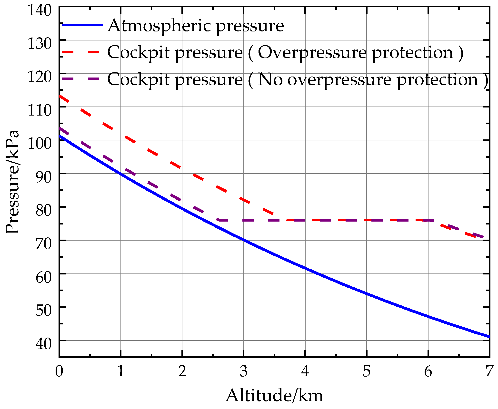
4.4.2. Cabin Overpressure Protection Threshold

The cabin must maintain a certain positive pressure during the helicopter’s stationery and flight processes to prevent the ingress of external nuclear chemical agents. The overpressure protection threshold value can be given as [31]
P = K ρ V 2 2
where K is the aerodynamic coefficient, which is taken as 1 in this paper; ρ is the air density, which is chosen to correspond to the atmospheric density on an extremely cold day at −40 °C, approximately 1.5 kg/m3; V is the normal speed of the windward surface, considered to be 400 km/h.
The regulation governing the variation in absolute pressure and residual pressure with altitude is referred to as cabin pressure regulation. In accordance with the anticipated design requirements, the curve representing the cabin pressure regulations is depicted in Figure 8, where the atmospheric pressure is based on the International Standard Atmosphere (ISA) 1976.
When the helicopter is operating in an unprotected mode, the pressure differential between the interior and exterior of the cabin is approximately 2.3 kPa during the phase of free ventilation. In the fixed absolute pressure flight phase, the cabin pressure stabilizes at 76 kPa. In the overpressure protection mode, the pressure differential during the overpressure protection phase is determined based on Formula (28), which sets a threshold for a cabin pressure differential of 12 kPa. In the fixed absolute pressure flight phase, the cabin pressure remains stable at 76 kPa.

5. Dynamic Simulation of Helicopter NBC Protection System

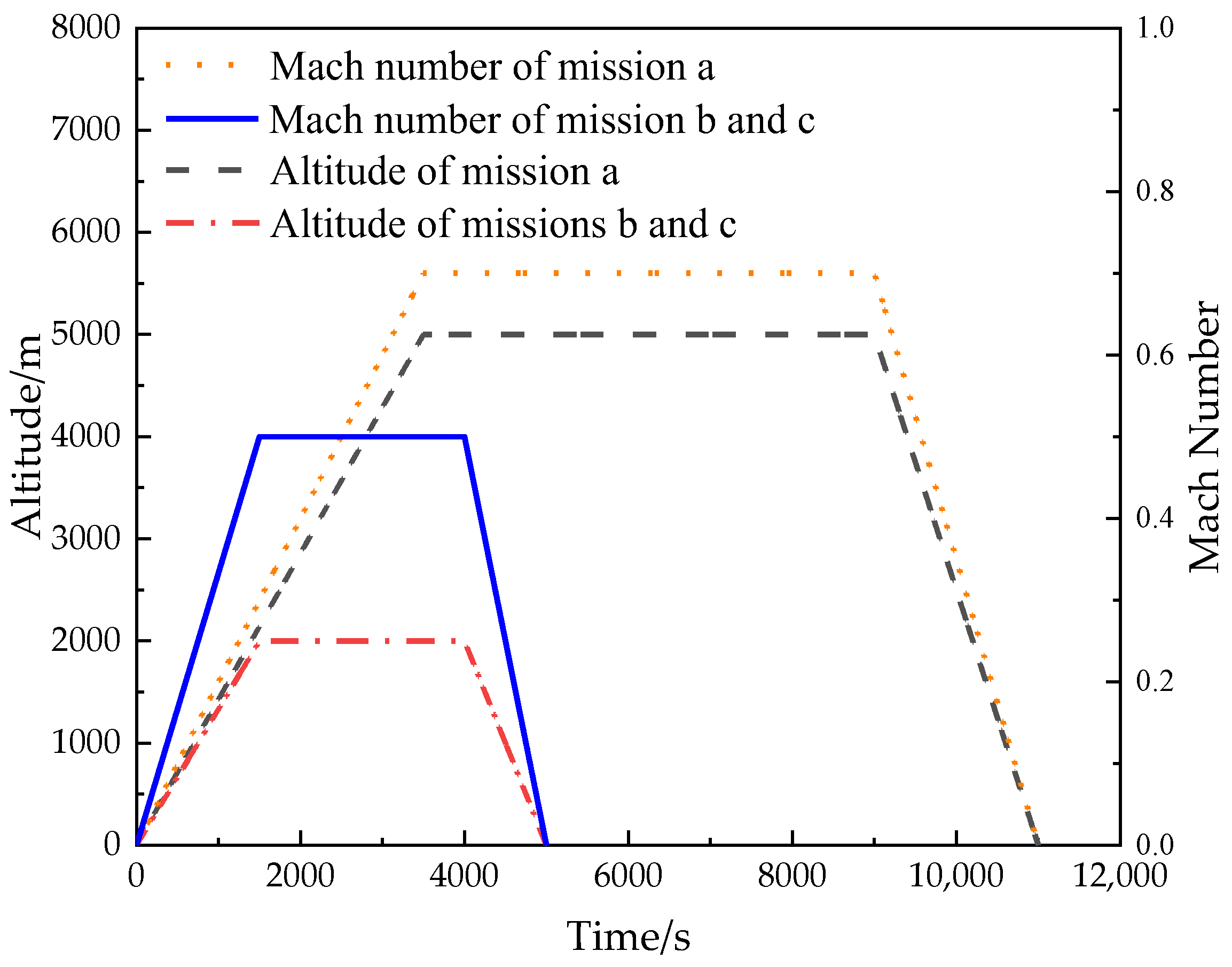
5.1. Simulation Model

The overall simulation model of the helicopter NBC protection system is established on the AMESIM simulation platform, as illustrated in Figure 9.

5.2. Simulation Parameter Setting

Due to the operational requirements of helicopters in various weather conditions, this article presents three types of flight missions: Flight mission A involves taking off under standard atmospheric conditions (15 °C), cruising at an altitude of 5 km, and continuing the mission for 11,000 s. Flight mission B is designed for extremely hot conditions during summer, with takeoff at a ground ambient temperature of 40 °C using ISA + 25 hot conditions. The helicopter will cruise at an altitude of 2 km and continue the mission for 5000 s. Lastly, flight mission C addresses extreme cold conditions during winter by utilizing ISA − 55 cold conditions. Takeoff occurs at a ground ambient temperature of −40 °C while cruising at an altitude of 2 km for a duration of 5000 s. The flight mission profiles are shown in Figure 10.
Each flight mission consists of two operational modes: no-protection mode and NBC filtration mode. Specific parameters are set for each mode during the simulation, as shown in Table 2. Regarding the configuration of the filtration ventilation subsystem, the following assumptions have been made: (1) adsorption bed A initiates operation first; (2) The helicopter remains within the NBC area throughout the entire 24 h flight mission.

6. Results and Discussion

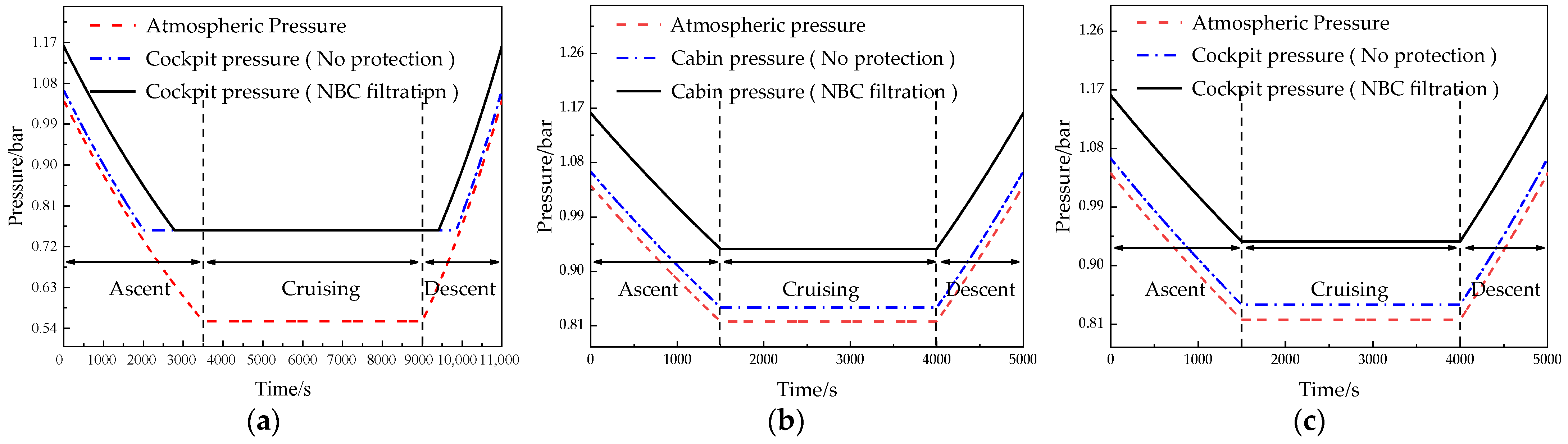
6.1. Pressure Control System Results and Discussion

The data in Figure 11 illustrates that during flight mission A when the cabin pressure altitude is below 2400 m, the pressure differential between the cabin and the external atmosphere environment is 2.3 kPa without protection and increases to 12 kPa with activated NBC filtration ventilation. As the cabin pressure altitude surpasses 2400 m, there is a gradual increase in the cabin residual pressure corresponding to the ascent in flight altitude, reaching its peak at 20 kPa. For flight missions B and C, where cruising altitudes are below 2400 m, the cabin residual pressure remains constant at 2.3 kPa without protection and rises to 12 kPa with activated NBC filtration ventilation as per design parameters.

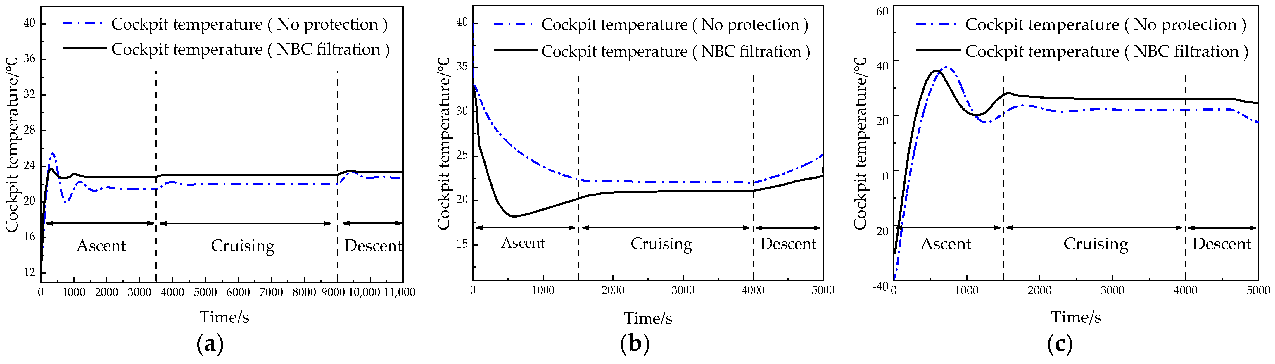
6.2. Temperature Control System Results and Discussion

The cockpit temperature exhibits distinct patterns during different flight missions, as depicted in Figure 12. For instance, in flight mission A, the cockpit temperature starts at 15 °C during the ascent phase and reaches a constant value of 22 °C throughout the cruise phase. During the descent phase, there is a slight increase in temperature while still within the comfortable range [32]. In flight mission B, the cabin temperature decreases from 40 °C to approximately 22 °C during the ascent phase and maintains this level during the cruise phase. A slight increase in temperature occurs during the descent phase. In flight mission C, there is a gradual rise in cockpit temperature from −40 °C to approximately −22 °C during the ascent phase, followed by a consistent level maintained throughout the cruise phase. The temperature slightly decreases during the descent phase due to external changes.
When the NBC filtration mode is activated, the cockpit temperature is influenced differently during each flight mission. In flight mission A, as external air passes through the renewable NBC filtration ventilation system, the cockpit temperature quickly rises to approximately 23 °C. It remains constant at 23 °C during the cruising phase with slight fluctuations within the specified temperature range during the descent phase. In flight mission B, during the ascent phase, the cockpit temperature rapidly drops from 40 °C to reach the target range and maintains within that range throughout the cruise phase. There is a slight increase in temperature during the descent phase due to external temperature changes. In flight mission C, during the ascent phase, the cockpit temperature gradually reaches approximately 24 °C from −40 °C and remains constant at the target temperature during the cruise phase, with a slight decrease during the descent phase.
A thorough comparison between the no-protection mode and the NBC filtration mode demonstrates that, in both conditions, the cockpit temperature is capable of meeting the specified design criteria. However, it is worth noting that in the NBC filtration mode, the intervention of the renewable NBC filtration ventilation subsystem leads to more efficient and rapid attainment of the intended design temperature.

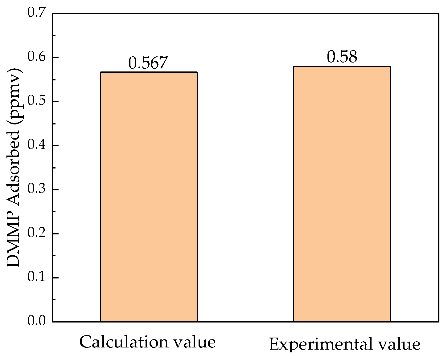
6.3. Renewable NBC Filtration Ventilation System Results and Discussion

Figure 13 illustrates that the DMMP content in adsorption bed A initially experiences a rapid increase until it reaches saturation during flight mission A. Adsorption bed B starts to adsorb, while adsorption bed A undergoes desorption. This cyclic process continues until exiting the NBC areas. The same pattern is observed in flight missions B and C as well. Throughout all three flight missions, there is an alternating trend in the DMMP content within the layers of adsorption beds A and B, with a maximum adsorption amount of 498 ppmv and an adsorption rate of 99.6%, which meets the stipulated design criteria.

7. Conclusions

A novel helicopter NBC protection system has been proposed to ensure the safety and comfort of helicopter aircrews in an NBC environment. The detailed configuration of each subsystem was designed, and a mathematical model of the components was established. To validate the performance of the helicopter NBC protection system designed, a dynamic simulation model has been built on the AMESIM platform, and three entire flight profile simulation was performed. The innovative contributions of this research paper are presented as follows:
  • A helicopter NBC protection system was designed from a top-level architecture with an advanced system-integrated approach that can comprehensively achieve functions including air source pressurization, renewable NBC filtration ventilation, as well as cabin temperature and pressure control. The system considers the characteristics of comfort and safety and provides a strong safeguard for the helicopter aircrew to work in the NBC environment.
  • Due to the short working lifespan of the traditional CPS and the need to replace the filter frequently, real-time renewable technology is adopted, which not only realizes the helicopter airborne renewable but also effectively prolongs the operational lifespan of the helicopter in the NBC environment.
  • The dynamic performance of the helicopter NBC protection system designed has been validated. The results demonstrate that the cockpit temperature and pressure can well satisfy the needs of aircrew with a helicopter; the renewable NBC filtration ventilation system realizes real-time airborne regeneration, and the maximum adsorption rate reaches 99.6%. The helicopter NBC protection system exhibits robust operation and can effectively adapt to significant changes in flight conditions.
  • This study provides a novel idea for the design of helicopter NBC protection systems so as to further optimize the design of helicopter NBC protection systems.

Author Contributions

Conceptualization, Y.W. and X.M.; methodology, H.W.; software, Y.W., and H.W.; validation, Y.W.; investigation, Q.Z.; resources, X.M. and L.P.; data curation, Q.Z.; writing—original draft preparation, Y.W.; writing—review and editing, Y.W. and X.M.; visualization, H.W.; supervision, Y.W.; project administration, X.M. and L.P.; funding acquisition, X.M. and L.P. All authors have read and agreed to the published version of the manuscript.

Funding

This research was funded by The Liao Ning Revitalization Talents Program, grant number XLYC1802092.

Data Availability Statement

Data are contained within the article.

Conflicts of Interest

The authors declare no conflicts of interest.

References

  1. Sun, X.; Liu, H.; Wu, G.; Zhou, Y. Training effectiveness evaluation of helicopter emergency relief based on virtual simulation. Chin. J. Aeronaut. 2018, 31, 2000–2012. [Google Scholar] [CrossRef]
  2. Sun, X.; Liu, H.; Tian, Y.; Wu, G.; Gao, Y. Team effectiveness evaluation and virtual reality scenario mapping model for helicopter emergency rescue. Chin. J. Aeronaut. 2020, 33, 3306–3317. [Google Scholar] [CrossRef]
  3. Yi, Y.; Chen, R.; Ji, H. An active flow control over the ship deck for helicopter shipboard operations. Aerospace 2024, 11, 119. [Google Scholar] [CrossRef]
  4. Russell, R.L.; Hoskins, R.S. Compatibility of a pressure breathing for G system with aircrew chemical defense. In Proceedings of the 29th Annual Symposium, Las Vegas, NV, USA, 9–11 April 1991; SAFE Association: Las Vegas, NV, USA, 1991; pp. 258–263. [Google Scholar]
  5. James, C.H. US Navy Marine Corps programs for aircrew chemical biological (CB) protection. In Proceedings of the 29th Annual Symposium, Las Vegas, NV, USA, 9–11 April 1991; SAFE Association: Las Vegas, NV, USA, 1991; pp. 156–160. [Google Scholar]
  6. Self, B.P. A comparison of the field of view of three chemical defense masks. SAFE J. 1999, 29, 79–84. [Google Scholar]
  7. Władysław, H.; Zbigniew, S.; Marian, S.; Adam, B. Collective protection measures-methods to ensure clean air. Cent. Rzeczoznawstwa Bud. 2023, 5, 53–71. [Google Scholar]
  8. Vicary, A.G.; Wilson, J. Nuclear biological and chemical defense. RUSI J. 1981, 126, 7–12. [Google Scholar] [CrossRef]
  9. Miller, R.E.; Lamontagne, R.A. Test and Analysis of Missile Exhaust Effects on the Collective Protection System. Nav. Eng. J. 1996, 108, 299–314. [Google Scholar] [CrossRef]
  10. Boerum, R.E.; Buck, K.P. Naval Ship Design Implications of the Collective Protection System. Nav. Eng. J. 1984, 96, 29–32. [Google Scholar] [CrossRef]
  11. Liu, L.; Luo, Q. Exploration and Thinking on Collective Protection System of Floating Nuclear Power Plant. J. Phys. Conf. Ser. 2021, 1802, 022030. [Google Scholar] [CrossRef]
  12. Morrison, R.W. Overview of current collective protection filtration technology. In Proceedings of the NBC Defense Collective Protection Conference, Baltimore, MD, USA, 30 October 2002. [Google Scholar]
  13. Li, C.; Tang, S.; Xu, Y.; Liu, F.; Li, M.; Zhi, X.; Ma, Y. Ultrasonic-assisted activated carbon separation removing bacterial endotoxin from salvia miltiorrhizae injection. Ultrason. Sonochem. 2024, 103, 106781. [Google Scholar] [CrossRef]
  14. Jerez, F.; Ramos, P.B.; Córdoba, V.E.; Ponce, M.F.; Acosta, G.G.; Bavio, M.A. Yerba mate: From waste to activated carbon for supercapacitors. J. Environ. Manag. 2023, 330, 117158. [Google Scholar] [CrossRef] [PubMed]
  15. Skoczko, I.; Szatyłowicz, E.; Tabor, A.; Gumiński, R. Manufacturing Options for Activated Carbons with Selected Synthetic Polymers as Binders. Materials 2024, 17, 1753. [Google Scholar] [CrossRef] [PubMed]
  16. Swetha, G.; Gopi, T.; Shekar, S.C.; Ramakrishna, C.; Saini, B.; Krishna, R. Breakthrough studies of Methyl salicylate and DMMP Mixed in Methyl salicylate with Pressure swing adsorption composed of 13X Molecular sieves. Def. Life Sci. J. 2016, 1, 155–161. [Google Scholar] [CrossRef]
  17. Carr, R.; Comer, J.; Ginsberg, M.D.; Aksimentiev, A. Microscopic Perspective on the Adsorption Isotherm of a Heterogeneous Surface. J. Phys. Chem. Lett. 2011, 2, 1804–1807. [Google Scholar] [CrossRef] [PubMed]
  18. Khaaday, W.A.; Majid, S.A.; Shekar, S.C.; Tomar, R. Synthesis and characterization of various zeolites and study of dynamic adsorption of dimethyl methyl phosphate over them. Mater. Res. Bull 2013, 48, 79–86. [Google Scholar]
  19. Horning, H.K. Performance Assessment of the DDG-51 Collective Protection System. Nav. Eng. J. 1994, 106, 118–125. [Google Scholar] [CrossRef]
  20. Pang, L.; Luo, K.; Yuan, Y.; Mao, X.; Fang, Y. Thermal performance of helicopter air conditioning system with lube oil source (LOS) heat pump. Energy 2020, 190, 116446. [Google Scholar] [CrossRef]
  21. Pinkard, B.R.; Shetty, S.; Kramlich, J.C.; Reinhall, P.G.; Novosselov, I.V. Hydrolysis of Dimethyl Methyl phosphonate (DMMP) in Hot-Compressed Water. J. Phys. Chem. 2020, 124, 167–178. [Google Scholar] [CrossRef] [PubMed]
  22. Mukhopadhyay, S.; Schoenitz, M.; Dreizin, E.L. Vapor-phase decomposition of dimethyl methylphosphonate (DMMP), a sarin surrogate, in presence of metal oxides. Def. Technol. 2021, 17, 1095–1114. [Google Scholar] [CrossRef]
  23. Ghosal, P.S.; Gupta, A.K. Determination of thermodynamic parameters from Langmuir isotherm constant-revisited. J. Mol. Liq. 2017, 225, 137–146. [Google Scholar] [CrossRef]
  24. Guo, X.; Wang, J. Comparison of linearization methods for modeling the Langmuir adsorption isotherm. J. Mol. Liq. 2019, 296, 111850. [Google Scholar] [CrossRef]
  25. Vieira, J.C.; Soares, L.C.; Froes-Silva, R.E.S. Comparing chemometric and Langmuir isotherm for determination of maximum capacity adsorption of arsenic by a biosorbent. Microchem. J. 2018, 137, 324–328. [Google Scholar] [CrossRef]
  26. Pang, L.; Zhao, M.; Luo, K.; Yin, Y.; Yue, Z. Dynamic temperature prediction of electronic equipment under high altitude long endurance conditions. Chin. J. Aeronaut. 2018, 31, 1189–1197. [Google Scholar] [CrossRef]
  27. Gorgy, E.; Eckels, S. Convective boiling of R-134a on enhanced-tube bundles. Int. J. Refrig. 2016, 68, 145–160. [Google Scholar] [CrossRef]
  28. Zajaczkowski, B.; Halon, T.; Krolicki, Z. Experimental verification of heat transfer coefficient for nucleate boiling at sub-atmospheric pressure and small heat fluxes. Int. J. Heat Mass Tran. 2016, 52, 205–215. [Google Scholar] [CrossRef]
  29. Sun, J.B.; Hyun, S.P.; Sung, J.Y.; Song, C.-H.; Choi, Y.-D.; Lee, S.-H.; Shin, J.-K. Study on the optimal heat supply control algorithm for district heating distribution network in response to outdoor air temperature. Energy 2015, 86, 247–256. [Google Scholar]
  30. Fu, L.; Tian, G.; Liang, B.; Shi, Q. Real Time Modeling and Simulation of Aircraft Cabin Pressure Control system. Computer Simulation. 2016, 2, 61–64+82. [Google Scholar]
  31. Fang, Y. Analysis of Overpressure and its Fluctuation of Naval Ships’ Collective Protection System. Chem. Def. Ships 2013, 3, 48–51. [Google Scholar]
  32. Qin, F.; Xue, Q.; Velez, G.M.A.; Zhang, G.; Zou, H.; Tian, C. Experimental investigation on heating performance of heat pump for electric vehicles at −20 °C ambient temperature. Energy Convers. Manag. 2015, 102, 39–49. [Google Scholar] [CrossRef]
Figure 1. Top-level architecture function module composition of the NBC protection system.
Aerospace 11 00633 g001
Figure 2. Top-level architecture of helicopter NBC protection system.
Aerospace 11 00633 g002
Figure 3. Configuration design of the air source pressurization subsystem.
Aerospace 11 00633 g003
Figure 4. Configuration design of the renewable NBC filtration ventilation subsystem.
Aerospace 11 00633 g004
Figure 5. Configuration design of the cabin temperature control subsystem.
Aerospace 11 00633 g005
Figure 6. Configuration design of the pressure control subsystem.
Aerospace 11 00633 g006
Figure 7. Verification result of DMMP adsorbed.
Aerospace 11 00633 g007
Figure 8. Curves of pressure variation with altitude.
Aerospace 11 00633 g008
Figure 9. Simulation model of the NBC protection system for the helicopter.
Aerospace 11 00633 g009
Figure 10. Flight mission profile.
Aerospace 11 00633 g010
Figure 11. Changes in cockpit pressure. (a) Flight mission A; (b) Flight mission B; (c) Flight mission C.
Aerospace 11 00633 g011
Figure 12. Changes in cockpit temperature. (a) Flight mission A; (b) Flight mission B; (c) Flight mission C.
Aerospace 11 00633 g012
Figure 13. Changes in DMMP adsorption capacity. (a) Flight mission A; (b) Flight mission B; (c) Flight mission C.
Aerospace 11 00633 g013
Table 1. The working conditions of DMMP in 13X molecular sieve [16].
ParameterValue
Adsorption temperature/K298.15
Adsorption pressure/bar5
Desorption temperature/K298.15
Desorption pressure/bar1.013
Table 2. Simulation parameters.
TitleParameterValue
CompressorDisplacement/cc·rev−1180
Volumetric efficiency0.6
Isentropic efficiency0.75
Mechanical efficiency0.9
CockpitTotal air volume of the/(kg/s)1.79
Size of the heat exchanger/mm737 × 240 × 70
Air-side heat exchange area/m214.2
Refrigerant-side heat exchange area/m20.59
The ratio between fresh and return air1.5:7.5
Equipment cabinTotal air volume/(kg/s)0.5
Size of the heat exchanger/mm478 × 240 × 70
Air-side heat exchange area/m29.2
Refrigerant-side heat exchange area/m20.38
Adsorption bedAdsorption rate/mL/s0.4 ppmv
Maximum adsorption capacity/ml500 ppmv
Desorption bedDesorption rate/mL/s0.4 ppmv
MaterialsWall materialsAluminum, Glass Fiber
RefrigerantR410A
Disclaimer/Publisher’s Note: The statements, opinions and data contained in all publications are solely those of the individual author(s) and contributor(s) and not of MDPI and/or the editor(s). MDPI and/or the editor(s) disclaim responsibility for any injury to people or property resulting from any ideas, methods, instructions or products referred to in the content.

