Article

Effects of Wire-Wrapping Patterns and Low Temperature on Combustion of Propellant Embedded with Metal Wire

1
National Key Laboratory of Solid Rocket Propulsion, Northwestern Polytechnical University, Xi’an 710072, China
2
The 41st Institute of the Fourth Academy of China Aerospace Science and Technology Corporation, Xi’an 710025, China
3
The Fourth Academy of China Aerospace Science and Technology Corporation, Xi’an 710025, China
*
Author to whom correspondence should be addressed.
Aerospace 2024, 11(8), 639; https://doi.org/10.3390/aerospace11080639
Submission received: 17 June 2024 / Revised: 2 August 2024 / Accepted: 4 August 2024 / Published: 6 August 2024
(This article belongs to the Special Issue Combustion of Solid Propellants)

Abstract

:
Incorporating silver wires into propellant has emerged as a highly effective strategy for enhancing propellant burning rates, a technique extensively deployed in the construction of numerous fielded sounding rockets and tactical missiles. Our research, employing a multi-faceted approach encompassing thermogravimetric-differential scanning calorimetry measurements (TG-DSC), combustion diagnoses, burning rate tests, and meticulous collection of condensed combustion products, sought to elucidate how variations in silver wire quantity and winding configuration impact the combustion properties of propellants. Our findings underscore the remarkable efficacy of double tightly twisted silver wire in significantly boosting propellant burning rates under ambient conditions. Moreover, at lower temperatures, the reduced gap between the propellant and silver wire further magnifies the influence of silver wire on burning rates. However, it is noteworthy that the relationship between burning speed and combustion efficiency is not deterministic. While a smaller cone angle of the burning surface contributes to heightened burning rates, it concurrently exacerbates the polymerization effect of vapor phase aluminum particles, consequently diminishing propellant combustion efficiency. Conversely, propellants configured with sparsely twinned silver wires exhibit notable enhancements in combustion efficiency, despite a less pronounced impact on the burning rate attributed to the larger cone angle of the burning surface. Remarkably, these trends persist at lower temperatures. Based on the principle of heat transfer balance, a theoretical model for the combustion of propellants with wire inserts is developed. The reliability of this theoretical model is validated through a comparison of calculated values with experimental data. Our research outcomes carry significant implications for guiding the application and advancement of the silver wire method in solid propellants for solid rocket motors, offering valuable insights to inform future research and development endeavors in this domain.

1. Introduction

Improving the burning rates of solid propellants stands as an enduring objective for propellant designers in the realm of solid rocket motor development. One widely adopted approach involves incorporating metal wires within the propellant matrix to heighten heat transfer to the unburned regions, thereby augmenting burning rates. In contrast to direct chemical methods aimed at enhancing the intrinsic burning rate of propellants, this technique offers simplicity, effectiveness, safety, and cost efficiency. Extensive experimental and computational investigations have been conducted to scrutinize the impact of metal wires on propellant combustion. Previous research laid the foundation for utilizing embedded metallic wires to bolster solid-propellant burning rate [1]. The effects of metal wire material, diameter, charge properties, and clearance on the burning rate of the end-loaded metal wire were systematically studied by numerical method, presenting a model for the combustion of wire-embedded propellants and juxtaposing the outcomes with empirical data [2]. The dataset encompassed diverse parameters such as pressures, wire diameters, and materials (e.g., silver, aluminum, copper, tungsten, platinum, and molybdenum). Numerical simulation was carried out on the combustion process of the embedded wire end combustion charge column, and a calculation model of the combustion rate of the embedded wire end combustion charge was established. Researchers have carried out a lot of simulation work on the numerical calculation of this aspect [3,4]. It was discerned that the enhancement in the burning rate from embedded wires hinges upon the thermal conductivity and melting point of the wire material [2,5,6,7]. Certainly, there is a refined version. Simultaneously, the burning rate demonstrates an upward trend with the augmentation of wire diameter until reaching a critical threshold, beyond which a smaller surface area ratio leads to a deceleration in the warming and burning rates [2,6,7,8,9]. The change in the burning rate of double-base propellants with silver wire was also studied. It was determined that the burning rate along the silver wire was controlled by the temperature gradient in the boiling region and the temperature in the dark region. The metal wire arrangement, the determination of position, and the selection principle of the number of metal wires in the engine with embedded wire powder column are studied [9]. The quantity of metal wires also influences the augmentation of the propellant burning rate. A greater dispersion of metal wires correlates with accelerated growth of the propellant burning surface and, consequently, an increase in burning rate [10,11]. The growth rate ratio of the fuel charge at the wire end was calculated, and the method of reducing the initial thrust peak value of the fuel column of the solid rocket engine at the wire end was discussed, and a series of characteristics of the fuel charge at the wire end were studied [12,13]. The technology of variable thrust in solid rocket motors can be realized through the incorporation of discontinuous wires within the propellant [14]. In practical engineering applications, inevitable gaps between silver wires and propellants during preparation and storage have been observed. Some studies indicate that smaller gaps between the wire and the propellant result in faster propellant burning [2]. It has been established that there exists a close relationship between the burning rate of a surface propellant and its initial temperature. Propellants with higher burn rates tend to exhibit lower temperature sensitivity, as evident from empirical data [15]. Moreover, the burning rate temperature sensitivity increases with rising initial temperatures [16]. However, the magnitude of the change in the temperature sensitivity coefficient diminishes as the initial temperature increases [17,18].
The combustion behavior of propellants embedded with metal wires is affected by factors such as wire material, diameter, quantity, and initial temperature of propellants, among which the higher the thermal conductivity and melting point of the metal wires, the greater the increase in propellant burning rate, and the number and distribution mode of the metal wires will also have a specific impact on propellant combustion. For propellants embedded with a single wire, the optimal diameter has been explored in previous studies. For propellants embedded with multiple wires, it has been shown in the literature that the distributed wire-embedding method and wound wire-embedding method have different influences on propellant combustion characteristics, while the specific influence of the wound wire-embedding method on propellant combustion is still unclear. In addition, the interaction between the wire and the propellant depends on the size of the gap between them, and the smaller the gap between the wire and the propellant, the greater the boost of the wire to the propellant burning rate. At the same time, the fluctuation of temperature will also cause the structural change in the propellant, which will change the clearance size, thus affecting the combustion rate. However, how the lower initial temperature affects the combustion of wire-embedded propellants is also poorly studied. In addition, changes in propellant combustion surface structure can also lead to changes in combustion efficiency, which has received relatively little attention.
Hence, this study endeavors to elucidate the following: (1) the influence of wire quantity and wrapping patterns between wires on the ignition performance and burning rate of three-component propellants; (2) the ramifications of various silver wires on the combustion behavior and resultant condensed combustion products of the three-component propellant (CCP); (3) the impact of initial temperature on the aforementioned properties under low-temperature conditions. The investigation employs TG-DSC analysis, combustion diagnostics, combustion rate quantification, and collection of combustion condensation products to examine how wire quantity and wrapping patterns influence ignition and combustion characteristics of solid propellants. The findings gleaned from this research bear significance in guiding the utilization of metal wires in solid propellant applications.

2. Experimental Methodology

The ternary hydroxyl group propellant primarily consists of an oxidizer, HTPB binder, aluminum powder, and various functional additives. The oxidizer AP constitutes 66% of the total content, with two distinct specifications: one featuring an average particle size of 135 microns and a standard deviation of 1.7 microns, and the other with an average particle size of 6 microns and a standard deviation of 0.3 microns. Both specifications follow a normal distribution for particle size distribution. Additionally, 8% of the total composition comprises other functional additives, including 6% for the burn rate catalyst C18H26Fe, 1.9% for the plasticizer C26H50O4, and 0.1% for the antioxidant C18H16N2 (Shaanxi aerospace Power Research Institute Co., Ltd., Xi’an, China). In comparison to conventional propellant formulations characterized by smaller grain dimensions, the embedded wire propellant exhibits an augmented comprehensive burning rate. Traditional propellant configurations typically manifest dimensions of 5 × 5 × 100 mm, featuring a brief steady-state segment. Hence, modifications were introduced to the propellant grain size, augmenting it to 7 × 7 × 200 mm. The rationale behind enlarging the cross-sectional dimension is to facilitate enhanced observation of the cone angle formation during the wire’s combustion process. Amplifying the cross-sectional area enhances the clarity of the cone angle, thereby facilitating easier identification. In the preparation phase, the wire is secured at both ends using fixtures, subsequent to which the propellant slurry is poured into the prefabricated 7 × 7 × 200 mm groove via the feeding orifice. Subsequently, the composite is cured at +50 °C to undergo sulfurization. Upon completion of the curing process, the fixtures at either end of the propellant are loosened, facilitating the removal of the wire-embedded propellant from the groove, thereby concluding the preparation process. Among usual metals, silver possesses the second highest thermal conductivity after gold. Its exceptional thermal conductivity (458.9 W/(m·K)), high ductility (50%), and high melting point (960 °C) make silver a preferred material for enhancing the acceleration ratio in solid rocket engines, thereby improving the burn rate of solid propellants. Compared to metals such as copper, aluminum, tungsten, and molybdenum, silver is particularly suitable for embedding into propellant grains. The wrapping pattern of the silver wires embedded in the propellant used in this experiment is shown in Table 1 and Figure 1a.
The combustion behavior and agglomeration phenomena on the propellant surface were investigated utilizing a combustion diagnosis device. Illustrated in Figure 1, this apparatus comprised a combustion chamber main body, an optical photographing system, an ignition control system, a data acquisition system, and a nitrogen inlet/exhaust system. The propellant was configured into 45 × 7 × 7 mm strands coated with insulation material (comprising 8% polyvinyl butyral and 92% absolute ethanol) to achieve a parallel regressing burning surface. An electrically triggered igniter was positioned directly above the propellant, and nitrogen was injected into the combustion chamber to attain the desired experimental pressure. Ethanol was employed as the quenching liquid, as the particles collected in ethanol exhibited a smaller size and were inert. The high-speed camera was set to a resolution of 1024 × 1024, a frame rate of 1000 fps, and an exposure time of 30 μs. Prior to testing, a thermocouple was embedded in the central part of the propellant sample, which was then coated with polyvinyl alcohol solvent for flame retardation and allowed to dry naturally. Each temperature profile was derived from the average of three measurements conducted under identical conditions. During the sample’s combustion, the thermocouple gradually approached the burning surface until it entered the flame zone, enabling the comprehensive recording of the propellant’s entire burning process and the acquisition of the combustion wave transitioning from the condensed phase to the gas phase.
The experimental method for measuring the propellant burning rate is depicted in Figure 1b. A thermocouple designated as a thermocouple (WRe3–25), featuring a single-filament diameter of 80 μm, is employed in this study. Its sampling frequency is set at 50 Hz. Two thermocouples were embedded within the propellant, and the sample was then coated with a polyvinyl alcohol-formaldehyde solution (three times), then dried naturally in air, with the distance between their temperature measurement points recorded. As the propellant ignites and burns continuously, temperature signals from the two thermocouples are sequentially transmitted to a signal collector. The time delay between these collected signals determines the burning rate of the propellant. The primary source of uncertainty in temperature measurement during this experiment stems from inherent errors associated with the thermocouple itself. Due to limitations in the experimental setup, the current calibration of the thermocouple is performed solely in hot water maintained at a constant temperature of 70 °C. These calibration results exhibit excellent repeatability, with a relative temperature measurement difference of 1%. It is acknowledged that the combustion temperatures of the propellants significantly exceed those of the hot water used for calibration. However, the main focus here is on qualitative comparison of temperature gradients among different propellants, allowing for a greater tolerance for temperature measurement errors. The error magnitude of other experimental data is represented on corresponding graphs or tables using error bars. Both the pressure sensor and thermocouple are interfaced with an acquisition device, through which pressure and temperature signals within the combustion chamber are captured and subsequently processed by a computer. The combustion efficiency of the propellant was determined through potassium dichromate titration. Initially, a measured quantity of CCP powder was placed into a beaker, followed by sequential additions of Fe2(SO4)3 solution, sulfuric acid solution, and saturated sodium bicarbonate solution. The mixture was then heated for over 30 min. After cooling, sulfur-phosphoric acid, a diphenylamine sulfonate indicator, and K2Cr2O7 solution were added in sequence. The titration endpoint was identified by the moment when the K2Cr2O7 solution transitioned from colorless to purple. The combustion efficiency w was calculated using the following formula:
w = 1 − c·Vi·M/(3G)
where c is the molar concentration of the K2Cr2O7 solution, Vi is the volume of K2Cr2O7 solution consumed, M is the molar mass of aluminum, and G is the mass of the CCPs. To ensure accuracy and reliability, each experiment was conducted three times, and the average results were used for subsequent analysis. Thermogravimetry-differential scanning calorimetry (TG-DSC) analyses were performed using a thermal analysis system (STA 449F3). Samples underwent heating from 30 °C to 1200 °C at a rate of 10 °C/min under argon purge gas at a flow rate of 40 mL/min and protective argon gas at 20 mL/min. Approximately 1 mg of powder was utilized per test. Propellant sample ignition was facilitated using ignition powder. High-magnification images of CCPs were captured utilizing a scanning electron microscope (SEM), with samples affixed to aluminum pins using carbon adhesive tape. The size distribution of CCPs was analyzed using a laser particle size analyzer (Mastersizer 2000, Worcestershire, UK).

3. Results and Discussions

3.1. Thermal Reactivity

TG-DSC is a critical technique for analyzing the combustion characteristics of propellants. It combines thermogravimetric analysis (TG) and differential scanning calorimetry (DSC) under controlled atmospheric conditions and programmed temperature settings. This method allows simultaneous measurement of mass changes and thermal effects of a sample, utilizing the same specimen throughout the analysis. TG measures the change in mass percentage of propellants embedded with silver wires during their reaction process, starting from an initial mass percentage of 100%, as depicted in Figure 2b. On the other hand, DSC records the absorption and release of heat during the thermal reaction process of the propellants, also illustrated in Figure 2a. The thermal reactivity of silver wire significantly impacts the ignition and combustion characteristics of propellants (see Table 2 and Table 3). The DSC curve reveals that propellants embedded with two silver wires exhibit higher heat release compared to those with single silver wires, and notably more than those without silver wires. An exothermic process is evident at 240 °C, denoted as the low-temperature decomposition (LTD) of ammonium perchlorate (AP), predominantly comprising solid-gas reactions, dissociation, and sublimation processes. Subsequently, the high-temperature decomposition process of AP ensues, where the gas phase controls the decomposition. AP decomposes entirely into volatile products such as NO, O2, Cl2, and H2O, with the decomposition peak temperature (HTD) recorded at 315 °C. While this trend aligns with findings in Liu Lu’s study, there are variations in specific reaction temperatures [19]. Notably, in G2, a heat absorption peak at 660.32 °C is observed, attributed to the melting heat absorption of aluminum. Conversely, this peak is scarcely discernible in other groups due to the minimal sample mass used during experimental determination, resulting in negligible heat absorption. Additionally, an exothermic peak at approximately 1150 °C is observed, attributed to the secondary oxidation of aluminum at high temperatures.
The thermogravimetric (TG) and differential thermogravimetry (DTG) curves are presented in Figure 2b,c. The decomposition of all four propellants initiates around 132 °C and concludes at 317 °C. Notably, G1 exhibits nearly complete mass reduction, while G2 experiences an 89.66% reduction, and G3 and G4 show reductions of 75.26% and 75.82%, respectively. The residual decomposition products in each group comprise silver oxide and aluminum oxide. The disparity in decomposition outcomes among the groups can be attributed to the absence or presence of silver wire, with G2 containing a single silver wire, and G3 and G4 each incorporating two silver wires. Analysis of the DTG graphs reveals nearly identical decomposition rates across the four propellants. However, a sequential slowdown in initial reaction temperatures is observed with an increase in the quantity of silver wire. This phenomenon is attributed to the higher specific heat capacity of silver wire, which absorbs more heat, consequently elevating the decomposition temperature of the propellant.

3.2. Ignition Delay and Burning Rate

The metal wire embedded within the propellant is subjected to elevated temperatures as the burning surface retreats, facilitating a heat transfer mechanism wherein the wire absorbs thermal energy from the surrounding gas. Consequently, the temperature of the wire increases, initiating a process of heat conduction into adjacent unexposed segments of the wire. This thermal energy is then conducted outward, elevating the initial temperature of the unignited propellant. Consequently, the burning rate of the propellant along the metal wire is heightened. This augmented burning rate fosters an accelerated exposure of the wire, thereby elongating the portion of the wire in contact with the gas and amplifying the heat absorption phenomenon. Concurrently, the temperature of the wire exposed to the gas gradually ascends until it reaches its melting point, establishing an “expose-melting” dynamic equilibrium. At this juncture, the wire growth effect attains its zenith and remains relatively stable until the depletion of the propellant. From the moment of ignition, the enhancing influence of the metal wire on propellant combustion undergoes a continuous evolution, progressing from insignificance to maximal efficacy. The incorporation of metal wires into the propellant increases the burning surface area, transitioning the combustion interface from a nominally planar configuration to a conical geometry. These embedded metal wires bolster the mass burning rate by facilitating enhanced thermal feedback from the product gas to the propellant contiguous to the conductor. This augmentation culminates in a localized escalation of the burning rate along the wire direction, thereby delineating a conical contour within the propellant. The half-angle of this cone is determined by the inverse sine of the basic propellant burning rate divided by the burning rate along the wire. While the propellant burns normally perpendicular to the conical surface in the absence of direct contact with the conductor, the augmented surface area associated with the cone fosters amplifications in both the mass production rate and the “effective” burning rate.
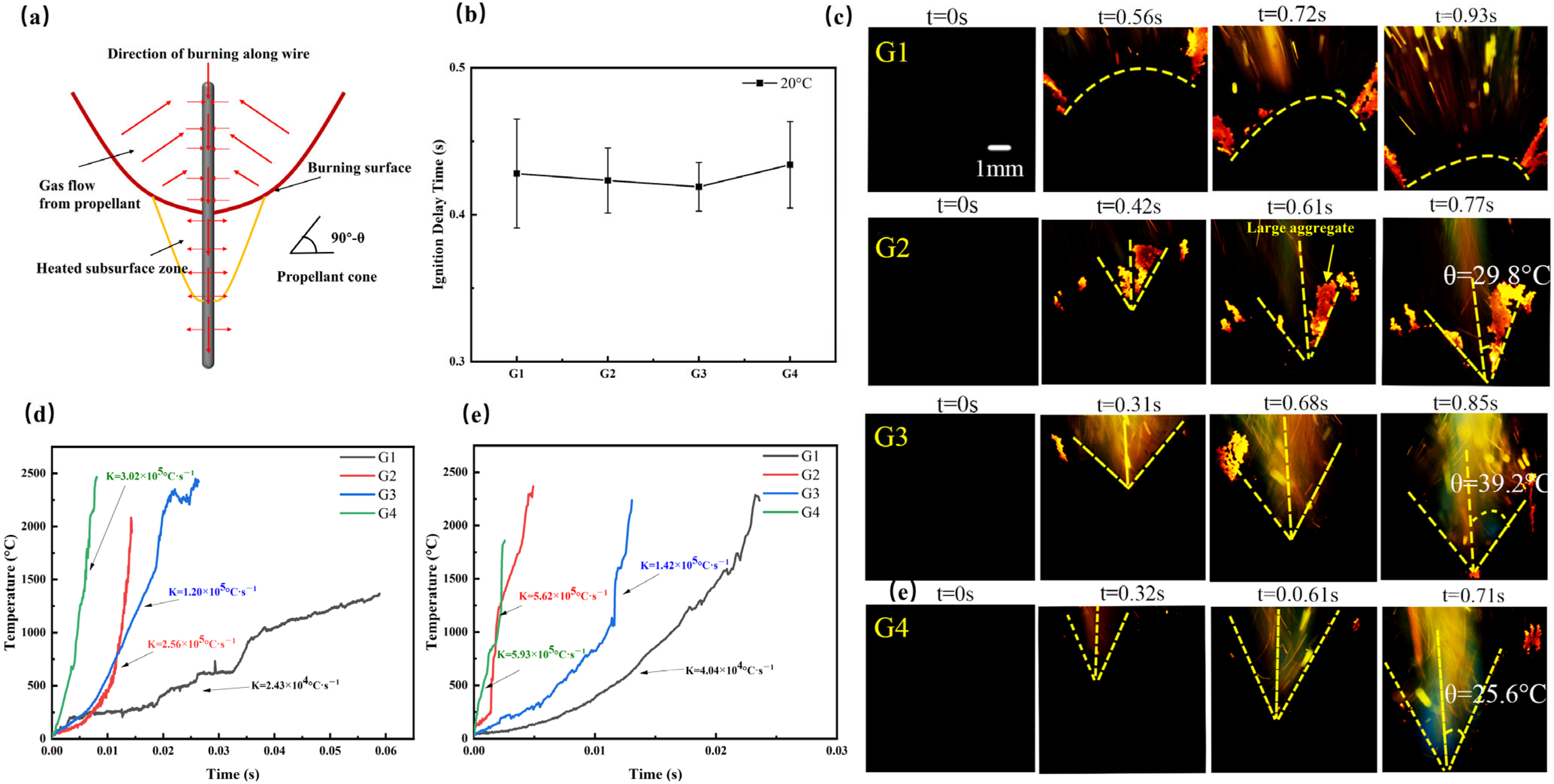
The ignition delay time denotes the duration required for an oxidizer crystal to ignite, assuming the onset of the ignition process coincides with the initial exposure of a crystal to the burning surface. As the burning surface traverses the crystal, heat is imparted to it, resulting in its gradual heating and eventual ignition. The time interval necessitated for this process to transpire constitutes the ignition delay time. As depicted in Figure 3b, the ignition delay time for the four propellants approximates 4.3 s and exhibits a stochastic distribution. In the propellant ignition stage, the metal wire does not affect the ignition of the propellant. Consequently, the burning rate of the propellant along the wire direction experiences augmentation. Given that the propellants employed in this study exhibit homogeneity in composition, with the sole variance being the incorporation of silver wire, it follows that the metal wires do not engender improvements in the ignition delay of the propellant during the initial ignition phase.
When metal wires augment propellant combustion, the adjacent propellant assumes a conical burning surface configuration, thereby augmenting the overall burning surface area during propellant combustion. The half apex angle of the resultant cone formed by the burning surface, where silver wires are embedded, defines the burning cone angle of the propellant containing these wires. The magnitude of this burning cone angle θ serves as a proxy for the propellant’s burning rate, with smaller cone angles indicative of larger burning surfaces and higher propellant burning rates. Analysis of the flame graph reveals that during the stable combustion phase, the propellant cone angles, from smallest to largest, are G4, G2, and G3. Notably, G4 exhibits the smallest burning surface cone angle at only 25.6 °C, while G3, with the largest cone angle, reaches 39.2 °C. This disparity arises because G4, being closely enveloped by silver wires, boasts a larger total contact area between the wires and the propellant compared to G2, where the contact area is relatively smaller. Since there are two silver wires in G4 and only one silver wire in G2, the contact area between G4 and the surrounding propellant is larger than that of the silver wire in G2, and the heat conduction from the silver wire to the propellant is stronger. As a result, G4 burns faster than G2. Despite G3 having a larger contact area compared to G2, the increased distance between the two silver wires in G3 results in less concentrated heat transfer from the wires and limited heat generation from propellant combustion, rendering G3 less thermally conductive than G2. Quantitative assessment of temperature and burning rate employed the embedded thermocouple method. As illustrated in Figure 3d,e and Table 4, at 1 MPa, G4 exhibits an average heating rate of 3.02 × 10⁵ °C·s−1, with a burning rate of 82.6 mm·s−1, whereas G3 demonstrates an average heating rate of 1.20 × 10⁵ °C·s−1 coupled with a burning rate of 41.2 mm·s−1. At 6 MPa, G4 registers an average heating rate of 5.93 × 10⁵ °C·s−1 and a burning rate of 111.5 mm·s−1, while G3 records an average heating rate of 1.42 × 10⁵ °C·s−1 and a burning rate of 79.4 mm·s−1. Notably, both heating and burning rates of G4 surpass those of G3 significantly, consistent with the observed differences in burning surface cone angles. Additionally, both heating and burning rates at 6 MPa exceed those at 1 MPa across all conditions.

3.3. Condensed Combustion Products

Aluminum powder, a prevalent metal additive in current solid propellant formulations, serves various purposes. Its incorporation enhances propellant density, elevates engine-specific impulse, and mitigates high-frequency unstable combustion [20,21,22]. Nonetheless, owing to aluminum’s high ignition point, these metal powders tend to agglomerate on the propellant surface, forming larger particles. This phenomenon triggers a cascade of adverse effects, including intensified ablation and residue deposition, diminished combustion efficiency, and decreased specific impulse [23,24,25,26,27,28]. During aluminum particle combustion, CCPs are generated, exhibiting a broad distribution ranging from a few microns to several hundred microns. These CCP agglomerates primarily comprise molten aluminum (Al) and alumina (Al2O3), with particle sizes scaling up to hundreds or even thousands of microns [29,30]. The variability in particle size correlates with the extent of distributed combustion, signifying that the size of CCPs released from the burning surface diverges from that of the final combustion products [31,32,33,34,35,36].
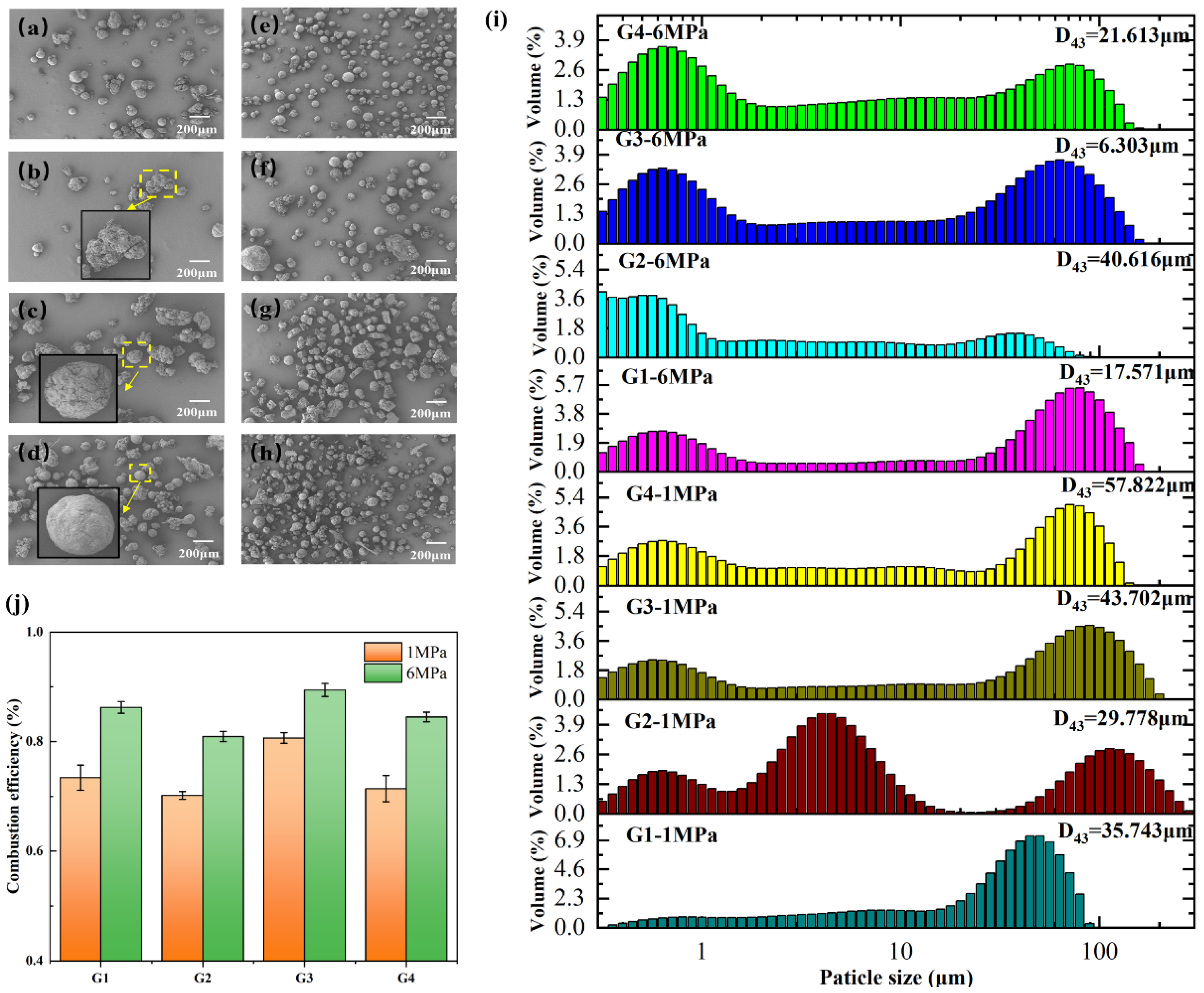
Moreover, the influence of metal wire on propellant combustion extends beyond mere alteration of the burning rate; it also impacts the combustion efficiency of the propellant [37]. An SEM of CCPs depicted in Figure 4 distinctly reveals disparities in aggregation and morphology induced by various silver wires. Each propellant’s CCPs comprises numerous coarse spherical agglomerates surpassing the initial aluminum size, ensconced by a layer of fine particles. Additionally, CCPs encompass incompletely burned, irregularly shaped propellant remnants, potentially attributable to discrepancies in propellant mechanical strength and high combustion chamber pressure. Notably, CCPs from G4 and G2 formulations feature sizable and irregularly shaped products. Conversely, in G3, CCP volume diminishes, predominantly presenting a spherical morphology. Furthermore, the surface of aluminum oxide in G3 combustion products appears rough, contrasting with the smooth surface observed in G2, suggesting a lower degree of oxidation. Consequently, G3 exhibits the smallest particle size, highest combustion efficiency, and the highest mass fraction of aluminum oxide among the products.
The smaller cone angle of the combustion surface in G4 and G2 formulations, as depicted in the schematic diagram of the cone angle of the combustion surface in Figure 3c, is accountable for the observed phenomena. During the combustion of silver-wire propellant, aluminum particles in the gas phase undergo polymerization and condensation into larger products owing to this unique conical burning surface. Consequently, the combustion efficiency of G4 and G2 is compromised. G3 has a faster burning speed than G1, so aluminum particles have a faster shedding speed on the combustion surface, impeding the formation of large agglomerations. The combined effect of these two factors contributes to the heightened combustion efficiency of G3. This finding aligns with existing research outcomes, challenging the conventional notion of an inherent correlation between combustion efficiency and burning rate. Unlike the prevalent approach of chemical methods in the prior literature to enhance the propellant burning rate and combustion efficiency [19,38,39], the current study underscores the significance of geometric considerations, such as cone angle, in modulating combustion dynamics.
The essence of employing the silver wire method to enhance the propellant burning rate lies in its impact on the propellant’s burning surface, diverging from approaches involving compositional alterations to improve burn rate. Consequently, this method does not yield identical effects on combustion efficiency. Figure 4b illustrates the size distribution of CCPs for various silver wire-propelled formulations. Typically, the size distribution of CCPs exhibits a critical size boundary, denoted as Dc, segregating CCPs into fine particles and aggregates. Fine particles comprise smoke oxide particles and residual oxide particles. Notably, the average particle size decreases progressively from G3 to G1, G4, and G2 formulations. Specifically, at 6 MPa, the average particle sizes are 6.303 μm, 17.571 μm, 21.613 μm, and 40.616 μm for G3, G1, G4, and G2, respectively, consistent with SEM findings, indicating G3’s pronounced capability in reducing aggregate size. Figure 4j delineates the weight fraction of Al2O3 in the combustion products. The combustion efficiency, ranging from G1 to G4, measures at 0.73, 0.70, 0.80, and 0.71 at 1 MPa, and 0.86, 0.80, 0.89, and 0.84 at 6 MPa, respectively. Notably, G3 exhibits a significant enhancement in combustion efficiency. This outcome, validated by SEM and particle size distribution analyses, underscores a positive correlation between combustion efficiency and pressure elevation. Similarly, when exploring the impact of low temperatures on propellant combustion efficiency, a consistent trend emerges, albeit with discrepancies in particle size laws at 20 °C and 1 MPa, potentially attributed to airflow instability during combustion product collection, leading to incomplete collection of certain combustion products.

3.4. Effect of Low Temperature

In practical engineering scenarios, the occurrence of interstices between silver wires and propellants is inevitable during the preparation and storage processes of the latter. Such interstices are substantially mitigated due to the shrinkage behavior exhibited by propellants at reduced temperatures. Prior investigations have delineated the influence of the gap between silver wires and propellants on the burning rate of the latter, establishing a negative correlation: greater gaps correlate with diminished burning rates [2]. Furthermore, it has been elucidated that lower initial temperatures exert an analogous effect on propellant burning rates [12,13,14].
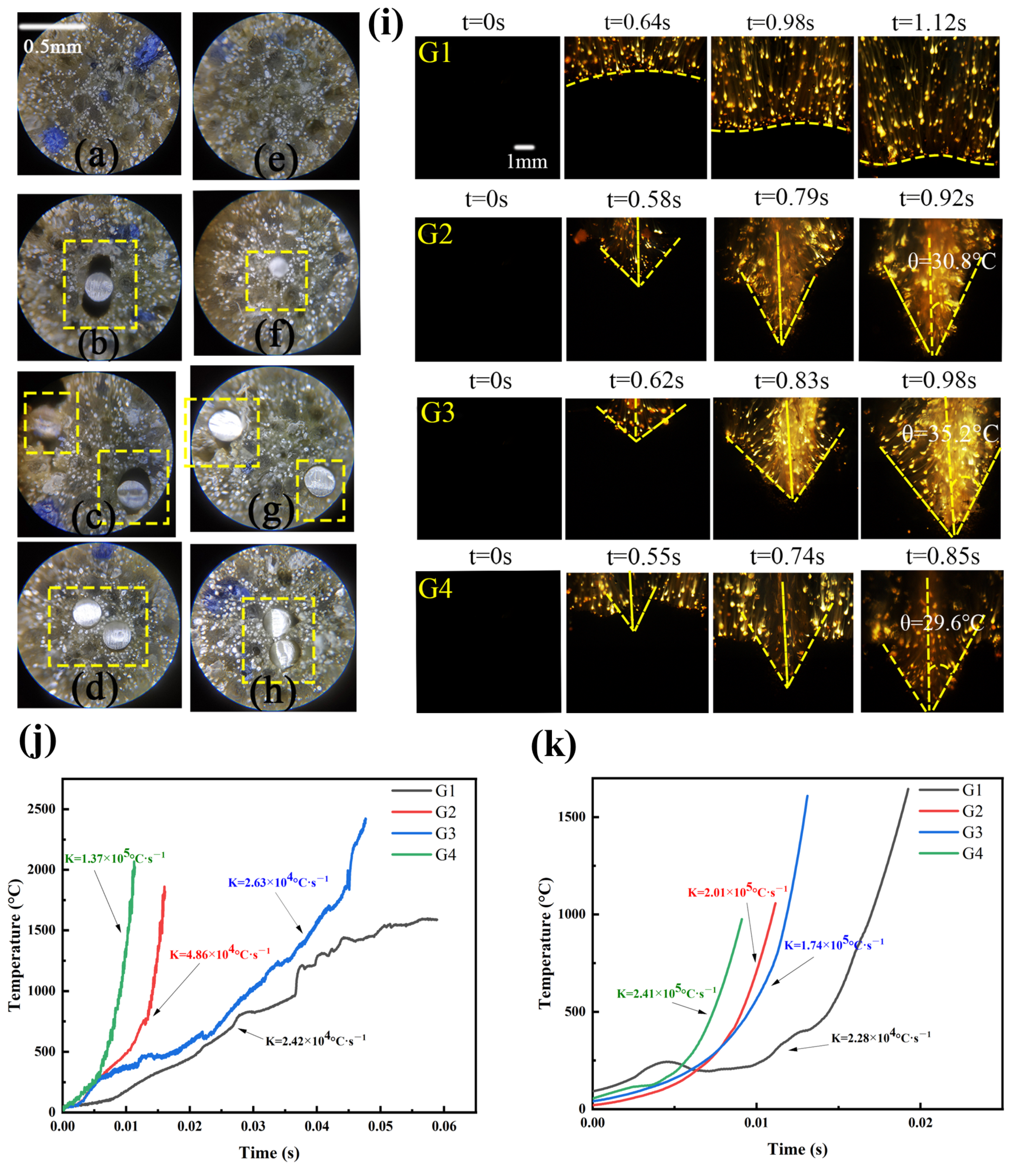
Microscopic examinations conducted at temperatures of 20 °C and −40 °C corroborate a notable reduction in the interstices between silver wires and propellants in Figure 5a. Evidently, a lower initial temperature engenders a reduction in the fundamental burning rate of the propellant, while a narrower gap between the metallic wire and the propellant augments the burning rate. Consequently, it becomes imperative to scrutinize the resultant alterations in the propellant’s burning rate under the combined influence of these factors.
Figure 5i reveals distinctive propellant cone angles during the phase of stable combustion, with G4 exhibiting the smallest angle, followed by G2 and G3, successively. Specifically, the burning surface cone angle for G4 measures 29.6 °C, whereas for G3, possessing the largest cone angle, it registers at 35.2 °C. Despite the propensity for diminished propellant combustion at lower temperatures, each group of propellants manifests an increase in burning surface cone angles. Notably, the increment in cone angle is most pronounced in the G3 group, indicative of a reduction in the interstices between silver wires and propellants. This reduction markedly enhances the combustion rate of the propellant, corroborated by quantitative assessments employing thermocouples in Figure 5j,k. The observed phenomenon can be attributed to the influence of interstices between silver wires and propellants on thermal conduction, leading to inadvertent heat dissipation that compromises the propellant’s combustion rate. Optimal thermal conductivity between silver wires and propellants is achieved only when they are in close proximity. The findings on combustion efficiency at −40 °C are similar to those at 20 °C in Figure 6.

3.5. Numerical Model and Model Calculation

Leveraging the fundamental law of heat transfer equilibrium, we developed a theoretical framework for the combustion of propellant containing embedded silver wire [14]. The model primarily incorporates convective heat transfer and thermal radiation interactions between the metal wire and the gas phase, heat conduction from the metal wire to the propellant grain, as well as convective heat transfer and thermal conduction within the gas and the grain.
The formula governing heat transfer between the metal wire and the gas phase is as follows:
Q f g i n = λ f T f x A f d t + q f g l d x d t
Q f g o u t = λ f x ( T f + T f x d x ) A f d t
where Qf-g-in is the heat transfer from combustion gas to the metal wire, Qf-g-out is the heat transfer from the metal wire to combustion gas, λf is the heat conduction coefficient of the metal wire (W/(m·K)), Tf is the temperature of the metal wire (K), Af is the cross-section area of the metal wire (m2), qf-g is the heat transfer density between combustion gas and the metal wire (W/m2), l is the perimeter of the metal wire (m); t is the operation time (s).
The heat transfer formula between the metal wire and the grain is
Q f p i n = λ f T f x A f d t q f p l d x d t
Q f p o u t = λ f x ( T f + T f x d x ) A f d t
where Qf-p-in is heat transfer from combustion gas to the metal wire, Qf-p-out is heat transfer from the metal wire to the grain, and qf-p is heat transfer density between the grain and the metal wire (W/m2).
For the heat convection between the combustion gas and the grain, the heat transfer processes are very complicated. In order to simplify the process, it was assumed that the temperature of the grain’s burning surface was the ignition temperature, which is defined by Equation (5).
Ts = Ti
where Ti is the ignition temperature of the grain (K); Ts is the burning surface temperature of the grain (K). Usually, the ignition temperature is 650 K, and the foremost part of the metal wire exposed to the gas is the melting point temperature of the metal wire. The surface of the grain is coated with insulating material, and it is assumed that heat transfer is zero except at the initial burning surface.
The heat conduction coefficient of silver wires is larger than that of the grain. The heat is transferred from the silver wire to the grain, while the silver wire is heated by combustion gas. This raises the temperature in the grain, which is close to the metal wire. When the temperature of the grain reaches the ignition temperature, the grain is ignited. The burning rate of the grain close to the metal wire increases faster, compared to the basic burning rate, which is obtained through experimental testing. Therefore, the burning rate ratio can be defined by Equation (6).
ω = 1/sin θ
We employ finite difference approximation (FDA) to rigorously formalize straightforward mathematical problems through discretization of partial differential equations. By transforming intricate calculus into algebraic expressions, we enable computational solving across numerous discrete points using programmed algorithms.
ρ p r o p C p _ p r o p v T i , j i + 1 T i , j i d t = k p r o p s 1 T i , j 1 T i , j d z + k p r o p s 3 T i 1 , j T i , j d r k p r o p s 1 T i , j T i , j + 1 d z k p r o p s 2 T i , j T i + 1 , j d r
where ρprop is the density of the propellant, Cp_prop is the specific heat capacity of the propellant, v is the volume of the propellant element, kprop is the thermal conductivity of the propellant, and s1, s2, and s3 are the side, upper, and bottom areas of the propellant element respectively.

4. Conclusions

We examined the influence of silver wire quantity, winding method, and low-temperature environments on the combustion dynamics of silver wire-embedded propellants. Utilizing a high-pressure combustion apparatus, we evaluated combustion rates and meticulously collected combustion products, providing a comprehensive analysis of propellants containing silver wire and elucidating the effects of silver wire on the combustion mechanism of aluminum-containing propellants.
TG-DSC analysis revealed that silver wire enhances heat release during the thermal decomposition process of the propellant, with heat release increasing proportionally to the number of silver wires present. Specifically, propellants embedded with two silver wires exhibited a heat release of approximately 315 J·g−1, while unsilvered propellants released about 161 J·g−1.
Interestingly, silver wire embedding had minimal impact on propellant ignition delay times, which averaged approximately 4.25 s. Propellants with tightly wound double silver wires demonstrated significantly increased combustion rates, exceeding those with single and sparsely wound silver wires at rates of 115 mm·s−1, 100 mm·s−1, and 84 mm·s−1, respectively. However, higher burning rates did not consistently correlate with increased combustion efficiency. Specifically, propellants with tightly wound double silver wires exhibited elevated combustion rates at ambient temperatures but reduced combustion efficiency due to a smaller cone angle on the combustion surface, which enhanced the polymerization effect of gaseous aluminum particles, thereby diminishing efficiency. In contrast, propellants embedded with double sparsely wound silver wires showed a larger cone angle during combustion, mitigating the polymerization effect of gas-phase aluminum particles and thereby enhancing combustion efficiency to 0.89.
At lower temperatures, the proximity between propellant and silver wire narrowed, amplifying the silver wire’s impact on combustion. Propellants embedded with two sparsely wound silver wires demonstrated a minimum mean particle size of 10.852 μm at lower temperatures, with few observed large aggregates. It is important to note that varying quantities and winding methods of silver wires yield distinct effects on combustion rate and efficiency. Propellants embedded with tightly wound double silver wires exhibited the most significant increase in combustion rate, whereas those embedded with double sparsely wound silver wires showed the highest increase in combustion efficiency, reaching 0.92.
Furthermore, based on the principles of heat transfer balance, we formulated a theoretical model for the combustion of propellants containing embedded wire. A comparison of the model’s calculated values with experimental data revealed that the majority of discrepancies were below 10%, affirming the reliability of the theoretical framework.
In conclusion, our study systematically analyzed the impact of silver wire winding methods on silver wire-embedded propellants. Double tightly wound silver wires effectively enhance propellant burning rates, ensuring favorable performance characteristics even at low temperatures. These findings contribute significantly to the advancement of solid propellant technology.

Author Contributions

Conceptualization, Q.W. and Q.R.; Methodology, J.Z.; Software, J.Z.; Formal analysis, J.Z.; Writing—original draft, Q.W.; Writing—review & editing, Q.W. All authors have read and agreed to the published version of the manuscript.

Funding

This research received no external funding.

Data Availability Statement

The raw data supporting the conclusions of this article will be made available by the authors on request.

Conflicts of Interest

Author Qiu Wu was employed by the company The 41st Institute of the Fourth Academy of China Aerospace Science and Technology Corporation. Author Quanbin Ren was employed by the company The Fourth Academy of China Aerospace Science and Technology Corporation. The remaining authors declare that the research was conducted in the absence of any commercial or financial relationships that could be construed as a potential conflict of interest.

References

  1. Rumbel, K.; Cohen, M.; Henderson, C.; Scurlock, A. A physical means of attaining high burning rate in solid propellants. In Proceedings of the Eleventh Army-Navy-Air Force Solid Propellant Meeting, Washington, DC, USA, 12–14 October 1955. [Google Scholar]
  2. King, M.K. Analytical modeling of effects of wires on solid motor ballistics. J. Propuls. Power 1991, 7, 312–321. [Google Scholar] [CrossRef]
  3. Gossant, B.; Godfroy, F.; Robert, P.H. Theoretical calculus of burning rate ratio in grains with embedded metal wires. In Proceedings of the 24th Joint Propulsion Conference, Boston, MA, USA, 11–13 July 1988; p. 3255. [Google Scholar] [CrossRef]
  4. Zhang, Y.; Wang, X. Numerical Research for Adjusting Thrust of Solid Rocket Motor by Using the Embedded-wire Grain. Acta Armamentarii 2007, 28, 1218. [Google Scholar]
  5. Rumbel, K.E. Poly(vinyl chloride) Plastisol Propellants. In Propellants Manufacture, Hazards, and Testing; Advances in Chemistry; American Chemical Society: Washington, DC, USA, 1969; Volume 88, pp. 36–66. [Google Scholar]
  6. Shuling, C.; Fengsheng, L. Influence of long metal wires on combustion of double-base propellants. Combust. Flame 1982, 45, 213–218. [Google Scholar] [CrossRef]
  7. Caveny, L.H.; Glick, R.L. Influence of embedded metal fibers on solid- propellant burning rate. J. Spacecr. Rocket. 1967, 4, 79–85. [Google Scholar] [CrossRef]
  8. Bakhman, N.N.; Lobanov, I.N. Influence of the diameter of the heat-conducting elements on their efficiency during the combustion of condensed systems. Combust. Explos. Shock Waves 1983, 19, 42–46. [Google Scholar] [CrossRef]
  9. Kubota, N.; Ichida, M.; Fujisawa, T. Combustion Processes of Propellants with Embedded Metal Wires. AIAA J. 1982, 20, 116–121. [Google Scholar] [CrossRef]
  10. Wilson, P.B. Tactical Missile Performance for Single and Multi-Wire Embedded Propellant Configurations with Discontinuities. 2019. Available online: https://scholar.afit.edu/etd/2238 (accessed on 1 August 2024).
  11. Rajak, R.; Lim, D.; Gnanaprakash, K.; Oh, J.; Yoh, J.J. Peculiar Burning Characteristics of Electrically Controlled Solid Propellants. In Proceedings of the 29th International Colloquium on the Dynamics of Explosions and Reactive Systems, Siheung-si, Republic of Korea, 23–28 July 2023. [Google Scholar]
  12. Xiao, Z.; Wang, J.; Wang, J. Method of Ablation Heat Shield Design of End-Burning Grain with Embedded Wire. Aerosp. Hanghai 2010, 2, 1006–1630. [Google Scholar] [CrossRef]
  13. Yu, N.; Yang, T.; Liu, W.; Li, L. Theoretical Performance Analysis of End-burning Grain Gas Generator Embedded with Silver-wire. J. Proj. Rocket. Missiles Guid. 2009, 29. [Google Scholar] [CrossRef]
  14. Wu, Q.; Ren, Q. Tuning the Ballistic Performance of a Single-Burning-Rate Grain Solid Rocket Motor via New Discontinuous Embedded Metal Wires. Aerospace 2024, 11, 308. [Google Scholar] [CrossRef]
  15. Cohen, N.S.; Flanigan, D.A. Mechanisms and models of solid-propellant burn rate temperature sensitivity—A review. AIAA J. 1985, 23, 1538–1547. [Google Scholar] [CrossRef]
  16. Atwood, A.I.; Boggs, T.L.; Curran, P.O.; Parr, T.P.; Hanson-Parr, D.M.; Price, C.F.; Wiknich, J. Burning Rate of Solid Propellant Ingredients, Part 2: Determination of Burning Rate Temperature Sensitivity. J. Propuls. Power 1999, 15, 748–752. [Google Scholar] [CrossRef]
  17. Liu, H.; Liu, J.; Yuan, J.; Chen, X.; Zhao, Y.; Xie, W. Initial Temperature Effects on the Combustion Characteristics of Al. Propellants Explos. Pyrotech. 2022, 47, e202100365. [Google Scholar] [CrossRef]
  18. Atwood, A.I.; Boggs, T.L.; Curran, P.O.; Parr, T.P.; Hanson-Parr, D.M.; Price, C.F.; Wiknich, J. Burning Rate of Solid Propellant Ingredients, Part 1: Pressure and Initial Temperature Effects. J. Propuls. Power 1999, 15, 740–747. [Google Scholar] [CrossRef]
  19. Liu, L.; Ao, W.; Wen, Z.; Zhang, Y.; Lv, X.; Qin, Z.; Liu, P. Combustion promotion and agglomeration reduction of the composite propellant using graphene. Aerosp. Sci. Technol. 2021, 118, 106988. [Google Scholar] [CrossRef]
  20. Ji, S.; Wang, B.; Zhao, D. Numerical analysis on combustion instabilities in end-burning-grain solid rocket motors utilizing pressure-coupled response functions. Aerosp. Sci. Technol. 2020, 98, 105701. [Google Scholar] [CrossRef]
  21. Zou, X.; Wang, N.; Wang, J.; Feng, Y.; Shi, B. A numerical investigation on heterogeneous combustion of aluminum nanoparticle clouds. Aerosp. Sci. Technol. 2021, 112, 106604. [Google Scholar] [CrossRef]
  22. Li, C.; Wu, G.; Li, M.; Hu, C.; Wei, J. A heat transfer model for aluminum droplet/wall impact. Aerosp. Sci. Technol. 2020, 97, 105639. [Google Scholar] [CrossRef]
  23. Liu, T.-K.; Perng, H.-C.; Luh, S.-P.; Liu, F. Aluminum agglomeration in ammonium perchlorate/cyclotrimethylene trinitramine/aluminum/hydroxy-terminated polybutadiene propellant combustion. J. Propuls. Power 1992, 8, 1177–1184. [Google Scholar] [CrossRef]
  24. Jackson, T.L.; Najjar, F.; Buckmaster, J. New Aluminum Agglomeration Models and Their Use in Solid-Propellant-Rocket Simularions. J. Propuls. Power 2005, 21, 925–936. [Google Scholar] [CrossRef]
  25. Orlandi, O.; Plaud, M.; Godfroy, F.; Larrieu, S.; Cesco, N. Aluminium droplets combustion and SRM instabilities. Acta Astronaut. 2019, 158, 470–479. [Google Scholar] [CrossRef]
  26. Liang, D.; Xiao, R.; Liu, J.; Wang, Y. Ignition and heterogeneous combustion of aluminum boride and boron–aluminum blend. Aerosp. Sci. Technol. 2019, 84, 1081–1091. [Google Scholar] [CrossRef]
  27. Li, L.-B.; Chen, X.; Musa, O.; Zhou, C.-S.; Zhu, M. The effect of pressure and oxygen concentration on the ignition and combustion of aluminum–magnesium fuel-rich propellant. Aerosp. Sci. Technol. 2018, 76, 394–401. [Google Scholar] [CrossRef]
  28. Babuk, V.A.; Vasilyev, V.A.; Malakhov, M.S. Condensed Combustion Products at the Burning Surface of Aluminized Solid Propellant. J. Propuls. Power 1999, 15, 783–793. [Google Scholar] [CrossRef]
  29. Xiong, W.Q.; Liu, Y.J.; Zhang, T.F.; Wu, S.X.; Zeng, D.W.; Guo, X.; Pang, A.M. Effect of Al-Li Alloy on the Combustion Performance of AP/RDX/Al/HTPB Propellant. Aerospace 2023, 10, 222. [Google Scholar] [CrossRef]
  30. Yue, S.C.; Liu, L.; Liu, H.; Jiang, Y.F.; Liu, P.J.; Pang, A.M.; Zhang, G.X.; Ao, W. Agglomerate Size Evolution in Solid Propellant Combustion under High Pressure. Aerospace 2023, 10, 515. [Google Scholar] [CrossRef]
  31. Liu, Z.; Li, S.; Liu, M.; Guan, D.; Sui, X.; Wang, N. Experimental investigation of the combustion products in an aluminised solid propellant. Acta Astronaut. 2017, 133, 136–144. [Google Scholar] [CrossRef]
  32. Babuk, V.A.; Vassiliev, V.A.; Sviridov, V.V. Propellant Formulation Factors and Metal Agglomeration in Combustion of Aluminized Solid Rocket Propellant. Combust. Sci. Technol. 2001, 163, 261–289. [Google Scholar] [CrossRef]
  33. Liu, T.-K. Experimental and Model Study of Agglomeration of Burning Aluminized Propellants. J. Propuls. Power 2005, 21, 797–806. [Google Scholar] [CrossRef]
  34. Naya, T.; Kohga, M. Influences of particle size and content of RDX on burning characteristics of RDX-based propellant. Aerosp. Sci. Technol. 2014, 32, 26–34. [Google Scholar] [CrossRef]
  35. Takahashi, K.; Oide, S.; Kuwahara, T. Agglomeration Characteristics of Aluminum Particles in AP/AN Composite Propellants. Propellants Explos. Pyrotech. 2013, 38, 555–562. [Google Scholar] [CrossRef]
  36. Cohen, N.S. A pocket model for aluminum agglomeration in composite propellants. AIAA J. 1983, 21, 720–725. [Google Scholar] [CrossRef]
  37. Golub, G. Need for a variable burning-rate solid propellant. J. Spacecr. Rocket. 1965, 2, 593–594. [Google Scholar] [CrossRef]
  38. Zhang, W.; Fan, Z.; Gou, D.; Shu, Y.; Liu, P.; Pang, A.; Ao, W. Elaborative collection of condensed combustion products of solid propellants: Towards a real Solid Rocket Motor (SRM) operational environment. Chin. J. Aeronaut. 2024, 37, 77–88. [Google Scholar] [CrossRef]
  39. Ao, W.; Liu, P.; Liu, H.; Wu, S.; Tao, B.; Huang, X.; Li, L.K.B. Tuning the agglomeration and combustion characteristics of aluminized propellants via a new functionalized fluoropolymer. Chem. Eng. J. 2020, 382, 122987. [Google Scholar] [CrossRef]
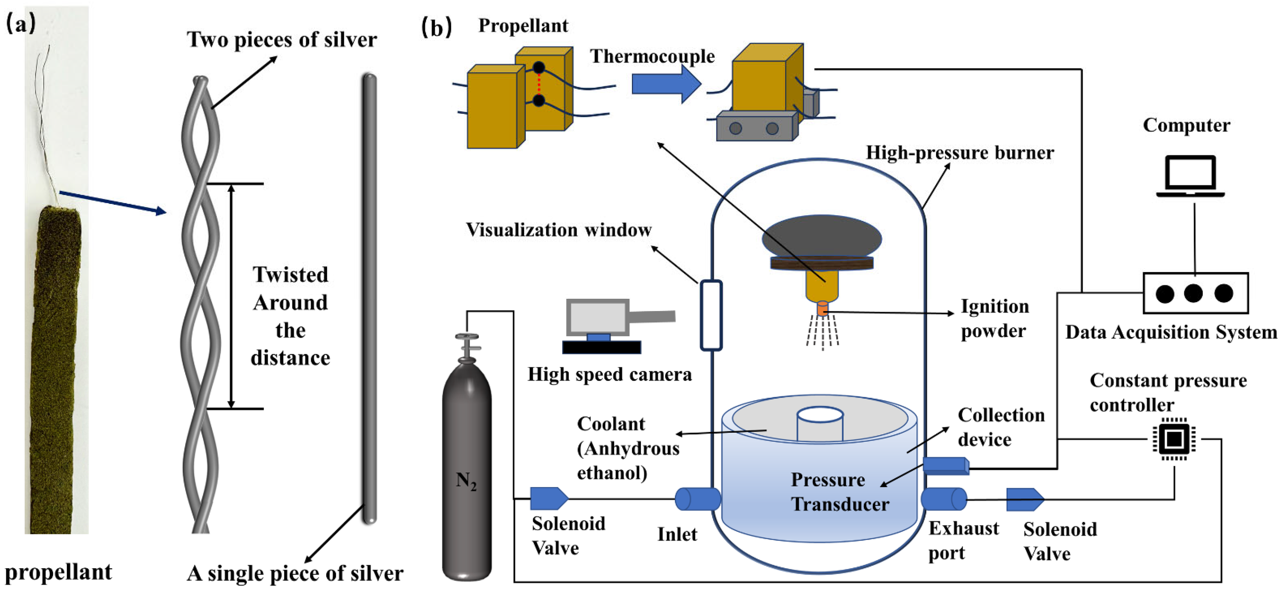
Figure 1. (a) The wrapping patterns of silver wires. (b) Multifunctional combustion diagnostic system.
Aerospace 11 00639 g001
Figure 2. (a) DSC; (b) TGA curves of the four types of silver wires in N2 with a heating rate of 10 °C·min−1; (c) DTG.
Aerospace 11 00639 g002
Figure 3. (a) Schematic of wired propellant combustion. (b) Ignition delay time at 1 Mpa. (c) Burning surfaces recorded by a high-speed camera. (d) The temperature curves during propellant combustion for all tested samples at 1 MPa. (e) The temperature curves during propellant combustion for all tested samples at 6 MPa.
Aerospace 11 00639 g003
Figure 4. (ad) SEM images of condensed combustion products showing agglomerates distributed in the products of G1, G2, G3, G4 at 1 MPa at 20 °C; (eh) SEM images of condensed combustion products showing agglomerates distributed in the products of G1, G2, G3, G4 at 6 MPa at 20 °C; (i) the size distribution of CCPs of propellant with different graphene content at 20 °C; (j) the weight Fraction of Al2O3 in combustion products at 20 °C.
Aerospace 11 00639 g004
Figure 5. (ad) microscopic profile of G1, G2, G3, G4 at 20 °C; (eh) microscopic profile of G1, G2, G3, G4 at −40 °C; (i) burning surfaces recorded by a high-speed camera at −40 °C; (j) the temperature curves during propellant combustion for all tested samples at 1 MPa at −40 °C; (k) the temperature curves during propellant combustion for all tested samples at 6 MPa at −40 °C.
Aerospace 11 00639 g005
Figure 6. (ad) SEM images of condensed combustion products showing agglomerates distributed in the products of G1, G2, G3, G4 at 1 MPa at −40 °C; (eh) SEM images of condensed combustion products showing agglomerates distributed in the products of G1, G2, G3, G4 at 6 MPa at −40 °C; (i) the size distribution of CCPs of propellant with different graphene content at −40 °C; (j) the weight fraction of Al2O3 in combustion products.
Aerospace 11 00639 g006
Table 1. Quantity and wrapping pattern of silver wires in propellant.
SampleQuantityWire Diameter (mm)Twisted around the Distance (mm)Surface Area of Silvered Wire per Unit Length of Propellant (mm2·mm−1)Surface-Volume Ratio (mm2·mm−3)
No silver wire(G1)0----
A piece of silver(G2)10.25-0.7816
twisted sparsely(G3)20.251001.5616
twisted tightly(G4)20.25501.5616
Table 2. TG and DTG characteristics for four types of silver wires.
Sample TG DTG
TiTeMC TpLmax
G1132.53306.18−102.79302.61
304.35
305.53
2.624
−65.21
6.58
G2132.53312.72−89.66309.11
311.75
−18.63
4.08
G3132.93316.32−75.26314.65
315.26
−11.53
1.66
G4133.15317.43−75.82314.97
316.07
−11.52
1.66
Note: Ti, initial reaction temperature (°C); Te, final reaction temperature (°C); MC, mass change (%); Tp, peak temperature of mass change (°C); Lmax, maximum mass change rate (% min−1).
Table 3. DSC curves for four types of silver wires.
SampleExotherm Peak
TpTiTeQ
G1234.69
274.88
305.29
1127.01
197.97
241.38
288.93
1069.2
241.38
288.93
320.47
1150.13
9.17
60.66
54.83
5.95
G2228.92
274.31
323.58
660.32
1131.62
193.93
243.28
313.06
650.43
1072.54
243.28
289.58
338.73
667.61
1180.14
10.73
79.23
156.21
−3.12
23.18
G3226.37
277.13
317.78
1107.14
197.98
241.21
292.77
1073.21
241.21
292.77
337.36
1188.12
7.38
69.11
222.80
16.16
G4225.62
279.13
314.72
1109.28
198.43
239.31
291.76
1071.43
242.26
295.77
335.36
1186.22
8.18
64.51
224.88
18.42
Note: Ti, initial reaction temperature (°C); Te, final reaction temperature (°C); Tp, peak temperature (°C); Q, heat release (Jg−1).
Table 4. Experimentally measured burning rates for different propellants at different pressure.
SampleStable Burning Length (mm)Burning Time (ms)Burning Rate (mm·s−1)
G1-1Mpa (20 °C)19.81.01404 (±0.021)30.52585 (±1.37)
G1-6Mpa (20 °C)19.90.425347 (±0.021)46.78532 (±2.1)
G1-1Mpa (−40 °C)20.11.487254 (±0.02)28.51484 (±1.17)
G1-6Mpa (−40 °C)20.10.47197 (±0.019)42.58747 (±1.73)
G2-1Mpa (20 °C)19.60.360963 (±0.019)54.29926 (±2.85)
G2-6Mpa (20 °C)200.199135 (±0.021)100.4343 (±3.16)
G2-1Mpa (−40 °C)200.437582 (±0.02)45.70569 (±1.99)
G2-6Mpa (−40 °C)19.50.205006 (±0.021)95.11936 (±3.45)
G3-1Mpa (20 °C)19.70.459847 (±0.019)42.84031 (±1.78)
G3-6Mpa (20 °C)19.80.234779 (±0.021)84.33481 (±2.62)
G3-1Mpa (−40 °C)19.80.486627 (±0.022)40.68823 (±1.60)
G3-6Mpa (−40 °C)20.10.221692 (±0.021)90.66646 (±2.50)
G4-1Mpa (20 °C)20.10.232092 (±0.02)86.60375 (±2.87)
G4-6Mpa (20 °C)20.20.175069 (±0.019)115.383 (±3.82)
G4-1Mpa (−40 °C)19.50.256719 (±0.02)75.95843 (±1.48)
G4-6Mpa (−40 °C)19.90.192009 (±0.019)103.6408 (±3.77)
Disclaimer/Publisher’s Note: The statements, opinions and data contained in all publications are solely those of the individual author(s) and contributor(s) and not of MDPI and/or the editor(s). MDPI and/or the editor(s) disclaim responsibility for any injury to people or property resulting from any ideas, methods, instructions or products referred to in the content.