Article

Analysis of Cable Shielding and Influencing Factors for Indirect Effects of Lightning on Aircraft

1
College of Electronic Information and Automation, Civil Aviation University of China, Tianjin 300300, China
2
Tianjin Aviation Equipment Safety and Airworthiness Technology Innovation Center, Tianjin 300300, China
*
Author to whom correspondence should be addressed.
Aerospace 2024, 11(8), 674; https://doi.org/10.3390/aerospace11080674
Submission received: 5 June 2024 / Revised: 9 August 2024 / Accepted: 12 August 2024 / Published: 16 August 2024
(This article belongs to the Special Issue Innovative Aircraft Electrical Power Systems)

Abstract

:
The widespread use of composite materials with low electrical conductivity in modern advanced aircraft has placed higher requirements on lightning protection for airborne equipment. To ensure the safe operation of aircraft under a lightning environment, the internal cables and cable tracks of composite aircraft are modeled. The lightning protection performance of cables is calculated for different types and shielding parameters, and the effect of the cable layout inside a composite aircraft on the protection performance is analyzed. The role of the cable track in lightning protection is also verified. The calculation results show that the cable shield and track structure can provide good lightning protection for the cable in the electromagnetic exposure area, and the layout of the cable inside the aircraft has a greater impact on the protection performance. The analysis of cable shielding measures and their influencing factors can provide a reference for the performance improvement of cable screening measures for the lightning protection of composite aircraft.

1. Introduction

Lightning is a natural discharge process with a high voltage and a large current at the boundary between high-density positive and negative charge concentrations. Its current rise speeds can reach 10–20 kA/μs, and its discharge energy can be up to hundreds of megajoules [1,2,3]. Lightning occurs at high frequency in nature, especially in the troposphere and stratosphere, which are the main areas in which aircraft fly. Statistics show that commercial aircraft are struck by lightning once a year [4]. When an aircraft is struck by lightning, the lightning’s transient pulses will electromagnetically couple to the internal cables of the fuselage and generate induced currents. Once the induced current is higher than the equipment interference threshold, it will cause damage to the airborne equipment or interfere with the internal systems [5,6]. Therefore, the electromagnetic compatibility (EMC) prevention of cables is the main measure for preventing electromagnetic interference caused by the indirect effects of lightning on aircraft [7]. Compared with traditional metal aircraft, Carbon Fiber-Reinforced Plastic (CFRP) aircraft are not able to channel and release lightning currents on the fuselage in a timely manner because of the low electrical conductivity of the material. And, the lightning electromagnetic pulse will penetrate the composite structure, further reducing the lightning protection capability of the fuselage of airborne equipment.
The main method for analyzing the indirect effects of composite aircraft is numerical simulation calculations [8,9]. To verify the shielding performance of the indirect effects of cables inside composite aircraft, anisotropic composite material models and electromagnetic coupling simulations of door joints and structural fasteners have been carried out. However, the mechanism behind the impact of lightning on aircraft has not been analyzed in detail [10]. Numerical simulation technology is used to estimate the coupling of the indirect effects of lightning on cables [11]. The shielding performance of internal aircraft cables in response to the indirect effect of lightning is not only affected by the fuselage material and skin gap but also by the layout of the cables in the fuselage. Aguilera et al. conducted a high-current pulse injection test analysis on various aircraft, including passenger aircraft, military aircraft, helicopters, and unmanned aerial vehicles. The distribution of surface currents and electromagnetic fields during different lightning current paths on the aircraft was analyzed. In addition, the effect of the layout of the cabin cables on the induced currents of the cables during lightning strikes has been discussed, but the effect on the protection of composite aircraft against lightning has not been further analyzed [12,13,14,15,16]. Piche analyzed the EMC performance of metal track structures inside composite aircraft by studying the mutual interference of cables in different slots inside the track [17]. Jaehyeon Jo et al. established an aircraft electromagnetic simulation model by analyzing the coupling effect of a lightning electromagnetic pulse on cables and further analyzed the factors that affect the electromagnetic coupling of indirect lightning effects. The design of protection measures against these indirect effects on cables was carried out, and a reference for the principles of cable laying was given [18].
In summary, many scholars have analyzed the indirect effect of lightning on aircraft and its protective measures, but further research is needed on the coupling mechanism between lightning and aircraft and the factors affecting cable shielding performance. Therefore, this paper will address this need in several parts, as follows:
Part 2 introduces the theory of induced currents generated by an aircraft after being struck by lightning, which includes factors such as the impedance of the aircraft fuselage, the impedance of the internal cable shield, and the aircraft grounding network, and provides a direction for further in-depth research on the indirect effects on aircraft.
Part 3 constructs an aircraft simulation model in CST Studio Suite 2020 software, observes the changes in the electromagnetic fields inside and outside the aircraft by injecting lightning current into the model, and analyzes the key changing parts of an electromagnetic field on the fuselage of the aircraft.
Part 4 uses different types of cables to observe the induced currents when the aircraft is struck by lightning. At the same time, based on the different cable shield grounding methods, a more in-depth investigation of the effects of induced currents on the aircraft model after lightning injection is carried out.
After the induced currents of the cables mentioned above are observed, in part 5, based on the obvious areas of electromagnetic field changes shown in part 2, the different types of cables in part 4 are placed in several key areas for experiments to obtain and analyze the induced currents in different areas. Based on the induced currents in the cables, the effect of metal track grooves on the generation of induced currents in the cables is investigated.
Finally, all the above experiments and results are analyzed to provide important references and protection suggestions for future all-electric/electronic aircraft against EMI.

2. Theoretical Calculation of the Indirect Effect of Lightning on Aircraft

2.1. The Principles behind the Indirect Effect of Lightning on Metal Aircraft

When an aircraft is struck by lightning, the lightning current I e x t , which is externally excited, is conducted through the lightning attachment point on the aircraft. Part of the current in the lightning current is diffusely conducted through the aircraft structure, while part of the current enters the interior of the aircraft and eventually couples with internal cables to generate induced currents [19].
Figure 1 shows an equivalent schematic diagram of the aircraft coupling mechanism. When an aircraft structure is made of metal, the impedance is mainly resistive. Its fuselage structural resistance R b o d y can be expressed by R s t , whereas for the internal cable shield of the aircraft, the shield resistance R s h i e l d can be expressed by R s h , and shield inductance L can be expressed by L s h .
Assume I s t is the current conducted through the aircraft structure and I int is the aircraft internal cable shield current, then
I e x t = I s t + I int
According to standard MIL-STD-464D [20], it is known that lightning current is a time-domain function, and the lightning current waveform is defined as a double exponential waveform. Thus, the expression can be written as
I e x t = I 0 ( e α t e β t )
where I 0 is the peak lightning current; α = 1 / T f a l l , T f a l l is the current fall time; and β = 1 / T r i s e , T r i s e is the current rise time.
From Kirchhoff’s voltage law, the following equation holds.
R s h I i n t + L s h d I i n t d t = R s t I s t
Substituting (1) into (3), we find that
R s h + R s t I i n t + L s h d I i n t d t = R s t I e x t
The solution of the differential Equation (4) can be obtained as
I int ( t ) = I 0 R st L sh e α t e λ t λ α + e λ t e β t λ β
where
λ = R s t + R s h L s h
From (5) and (6), the induced current of the cable shield inside the metal aircraft is determined by the lightning current parameters α , β , I 0 , the aircraft structural resistance R s t , and the cable shield impedance R s h and L s h .

2.2. The Principle of the Indirect Effect of Lightning on Composite Aircraft

In addition to the difference in material conductivity between metal and composite, differences in the internal structure also lead different lightning coupling mechanisms. The mechanism of lightning coupling to composite aircraft is more complex than that of metal aircraft because of the influence of the internal grounding. The ground of metal aircraft is the metal fuselage. Composite materials have a lower conductivity than metal, so a metal fuselage cannot provide a good grounding condition for aircraft. Therefore, a separate metallic grounding grid will be provided as a grounding in composite aircraft, and its influence needs to be considered [21,22]. When an aircraft is struck by lightning, the coupling process can be divided into two steps. In the first step, induced current in the aircraft grounding network is generated by the lightning current. Second, mutual inductance is generated between the grounding network and internal cables, and induced current is generated on the internal cables [19].
Similar to the analysis of induced current on metal aircraft, the structural resistance of the composite aircraft body can be expressed by R s t . Cable shield resistance can be expressed by R s h , and shield inductance can be expressed by L s h . The following additional parameter definitions are also added: R g n is the composite aircraft grounding grid resistance and L g n is the composite aircraft grounding grid inductance. M is the mutual inductance between the grounding grid and the cable, which is generated by the grounding grid current after the aircraft is struck by lightning. Assuming that the current in the grounding grid is I g n , since no induced current is generated in the grounding grid at this time, the mutual inductance between the grounding grid and the cable is not considered. Therefore, we conclude that
I g n ( t ) = I 0 R s t L g n e α t e η t η α + e η t e β t η β
where
η = R s t + R g n L g n
The second step in the equivalent circuit of the lightning current and cable coupling process is shown in Figure 2. Under these circumstances, lightning strikes the aircraft and generates induced current in the grounding network. The grounding network and the cable generate mutual inductance, which we express as
R s h I i n t + L s h d I i n t d t + M d I g n d t = R g n I g n + L g n d I g n d t + M d I i n t d t
Then, the composite aircraft cable shield current I int can be expressed as
I i n t ( t ) = I 0 R s t ( 1 e ω t ) R s h L g n ( L s h M ) 2 A e α t N e η t η α + N e η t B e β t η β
where
ω = R s h ( L s h M )
A = R g n α ( L g n M )
B = R g n β ( L g n M )
N = R g n η ( L g n M )
In summary, whether for a metal or composite aircraft, the induced current of the cable shield is determined by the parameters in (5) or (10) when a lightning strike occurs. Considering that the low conductivity of the composite material makes its structural resistance higher, and mutual inductance exists between the introduced metal grounding network and the cable, the induced current of the cable inside the composite aircraft deserves more consideration.

2.3. The Analysis of Metal Mesh in the Composite Aircraft Fuselage

A common method for indirect effect protection of composite aircraft is to lay a metal mesh on the skin surface. The principle of the method is to increase the electromagnetic loss when the electromagnetic field penetrates the skin. The coupling mechanism is shown in Figure 3.
When the composite aircraft surface is paved with metal mesh, parameter R m s is defined as the structural resistance of the metal mesh. Assume that the structural resistance R m s of the metal mesh is in parallel with the fuselage structural resistance R s t . Then, (10) can be written as
I i n t ( t ) = I 0 ( R s t / / R m s ) ( 1 e ω t ) R s h L g n ( L s h M ) 2 A e α t N e η t η α + N e η t B e β t η β
When the metal mesh is laid on the composite aircraft fuselage, the metal mesh and the fuselage structure can be considered as a whole. It can be concluded from (15) that the overall resistance R of the whole is reduced because of the parallel connection between the metal mesh resistance and the fuselage structure resistance. As a result, the induced current I int of the cable shield decreases, which verifies the indirect protective effect of laying metal mesh on composite aircraft.

3. Design and Analysis of the Indirect Effect of Lightning on Aircraft

3.1. Aircraft Model Construction and Excitation Source Setup

The composite aircraft lightning strike model was established in the CST simulation platform, as shown in Figure 4. The lightning current attachment point is set at the nose radome and the lightning current separation point at the tail. The aircraft model has a length of 33 m, a wingspan of 32 m, and a height of 6.7 m. The cockpit skin, doors, and leading edges of the wings are made of aluminum metal, the portholes are made of glass, and the rest of the fuselage skin is made of CFRP. In addition, CFRP is set as a quasi-isotropic material, and its monolayer conductivity is shown in Table 1 [23].
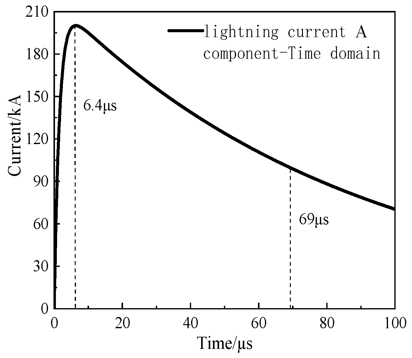
In this paper, a lightning current component A is used to calculate the high current pulse injection into an aircraft considering that it is usually used to simulate the excitation of an aircraft when it suffers from a lightning strike [24]. Its waveform is as shown in Figure 5. The peak value of the lightning current I0 = 218810 A, the reciprocal of current falling time α = 11354 s−1, and the reciprocal of rising time β = 647265 s−1.
Figure 5 shows that the lightning current reaches the peak in 6.4 μs, and then the current starts to decay with a half-peak time of 69 μs. The simulation time is set to 100 μs. In addition, considering that most of the lightning current energy is concentrated below 10 kHz, some high-frequency components are enhanced after the electromagnetic wave is coupled to the inside of the body.
Using CST studio suite 2020 simulation software, a cable is constructed inside the aircraft that is connected to the external skin, as shown in Figure 6, which is equivalent to the internal electrical cable of the aircraft and is used to observe and simulate the effect of the external lightning current passing through the fuselage on the internal cable. The metal mesh laid on the external skin is set in the material definition of CST simulation software for the relevant data of conductivity, thickness, and laying density, and the metal mesh is set in the corresponding area.
Based on the settings, the results of magnetic field intensity and induced current for the different types of aircraft are simulated, as shown in Table 2. The material are aluminum, CFRP, and CFRP combined with metal mesh.
It can be concluded from Table 2, the peak internal magnetic field intensity of the CFRP aircraft is about 15 times higher than that of the aluminum aircraft at the same location inside the aircraft, whereas the peak induced current of the coaxial cable shield is about 38 times higher, but these two values are reduced to 9 times and 12 times when a metal mesh is applied to the surface of the CFRP aircraft. In addition, the induced current on the core of the coaxial cable shows that the peak induced current of the core is reduced from 6.262 A to 1.942 A after using CFRP combined with metal mesh. This proves the correctness of the theory in Section 2.3 and also shows that the metal mesh provides good protection against indirect effects.

3.2. Lightning Passage through the Airframe

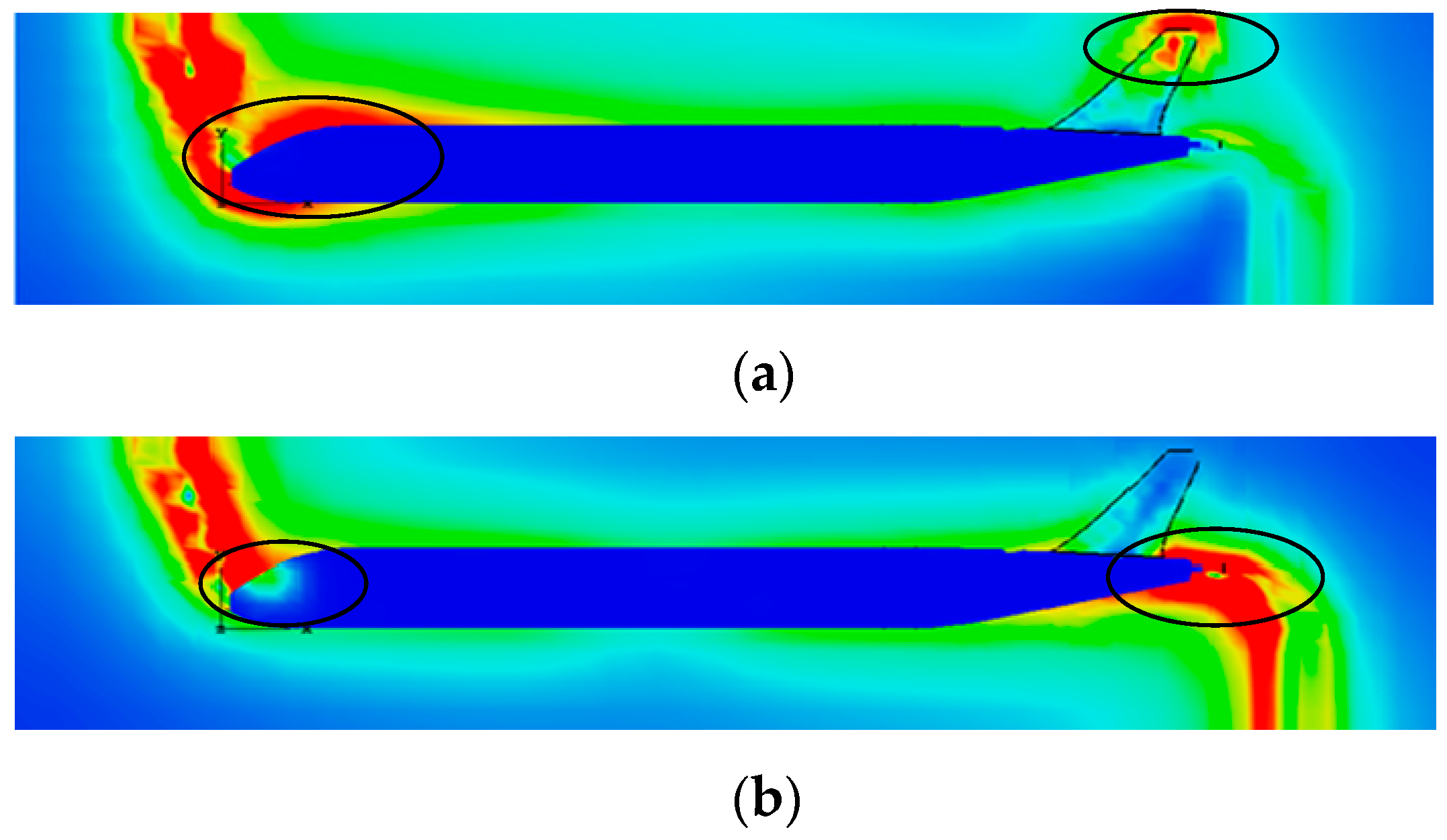
According to the model constructed in Figure 6, the spatial electromagnetic field distribution when the lightning current passes through the fuselage at the time of 6.4 μs can be obtained, as shown in Figure 7.
As can be seen in Figure 7, the distribution law of the electric field in space is that a location in the lightning current path in the electric field intensity is larger. In addition, in the smaller radius of curvature of a location such as the tip of the tail, the electric field intensity is also larger. Therefore, the distribution law of the magnetic field in space is different from the electric field in space, and the intensity of the magnetic field is larger only in the nose, fuselage, and the tail of the aircraft in the lightning current path.
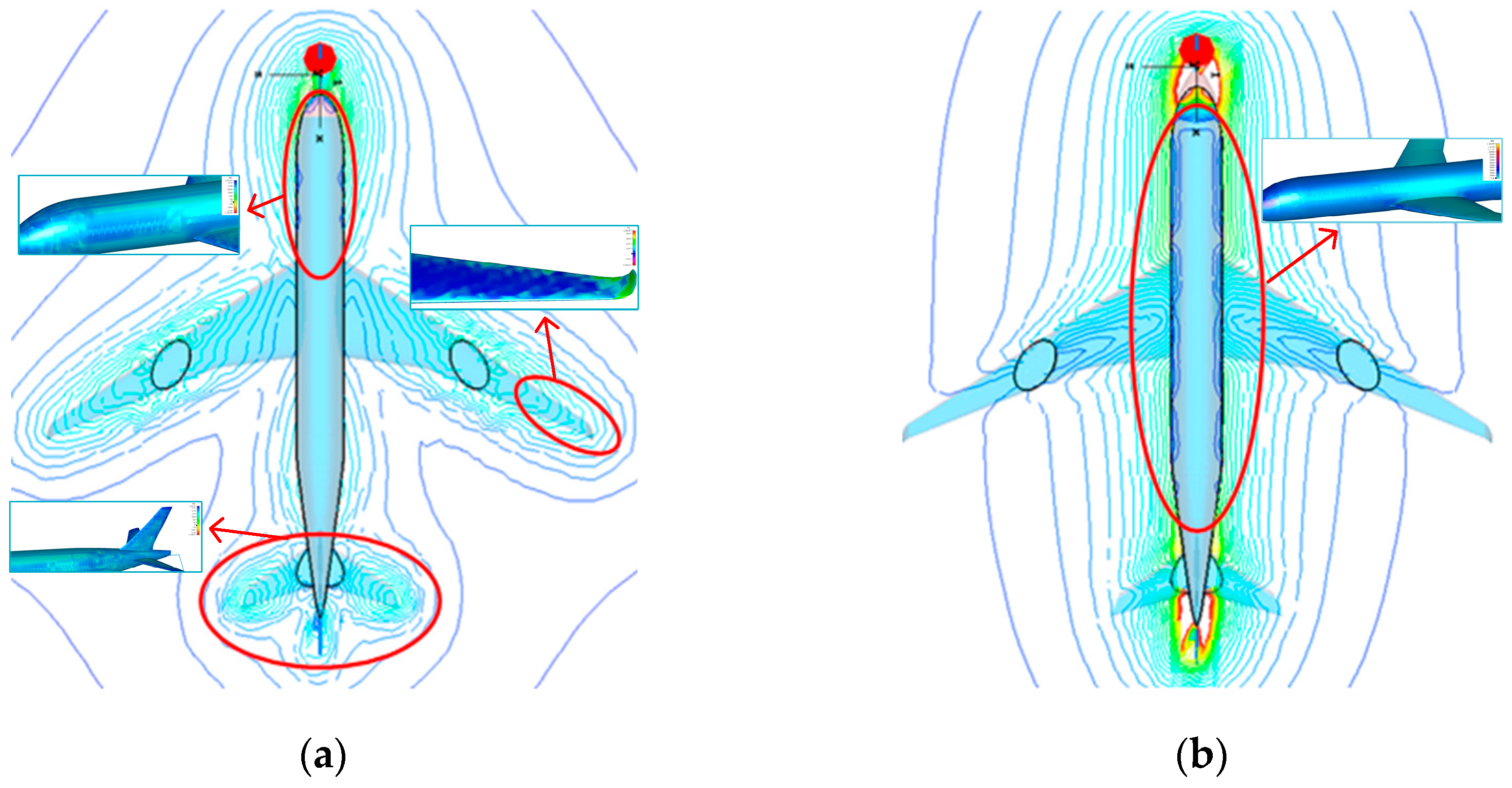
When an aircraft is struck by lightning, most of the EMP energy inside the fuselage is radiatively coupled from the lightning EMP through apertures or glass and other pathways, as shown in Figure 8.
Figure 8 shows that there is a large electromagnetic field near the cockpit portholes, passenger cabin portholes, and hatches. That is, when lightning strikes an aircraft, with the conduction of lightning current on the fuselage, electromagnetic energy will enter the interior of the fuselage through the glass of the aircraft’s portholes as well as the gaps in the hatches, generating electromagnetic interference to on-board equipment, electrical cables, and systems. Therefore, in the subsequent study, it is necessary to consider the effects of lightning current on cables at different locations on the fuselage including portholes and hatches.

4. Influence of the Cable Shielding Layer on Shielding Performance

4.1. Cable Type

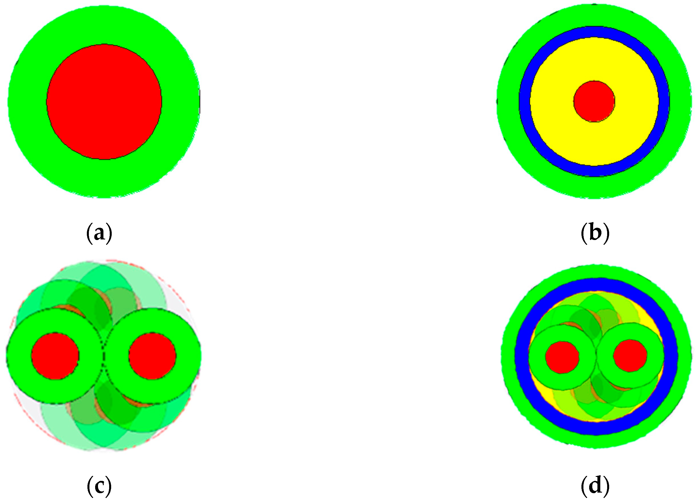
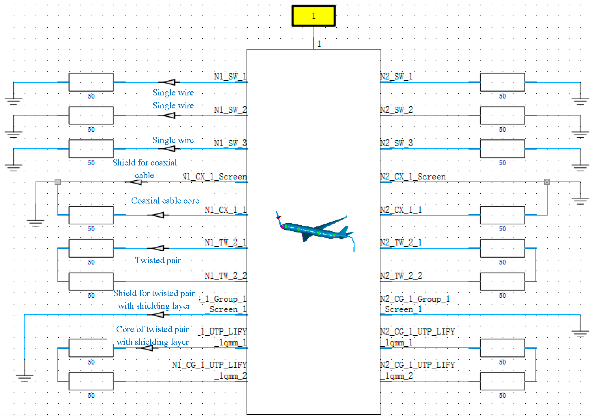
The cables within the aircraft that have different functions are single wires, coaxial wires, and twisted pairs, as shown in Figure 9.
We set up four kinds of cables with the same cross-sectional area of the core wire and bundled them into a wire bundle laid in the same location. We set the termination resistances of the different cables as follows: a single-core wire with 50 Ω resistors at each end; a coaxial wire with 50 Ω resistors at the core and the shield directly grounded; a twisted-pair wire with 50 Ω resistors at each strand; and a shielded twisted-pair wire with 50 Ω resistors at each strand and the shield directly grounded.
With the cable induced current as an index, for different types of cables, a comparison was made for different cable shielding measures in order to analyze the road simulation model shown in Figure 10 and the indirect effect of different types of cables.
The simulation model was built with the single wire, the coaxial wire with a shielding layer, the twisted pair, and the twisted pair with a shielding layer of four cables with the same core area. Then, in the same location of the aircraft’s laying, after the injection of lightning and sequential measurements, we obtained the inductance current of the single wire, the coaxial wire with a shielding layer, the twisted pair, and the twisted pair with shielding layer of cables. Different cables were laid inside the CFRP aircraft, and their protective performance was analyzed. The peak induced current of each cable is shown in Table 3.
Table 3 shows that the induced current of the coaxial wire with shielding layer is smaller than the single wire. The same result is observed for the twisted pair. This means that adding a shielding layer can provide better electromagnetic shielding. In addition, the shielding performance of the twisted pair is better than that of the single-core wire. Therefore, the electromagnetic exposure area and the cables transmitting important signals are used correspondingly according to different shielding performance requirements.

4.2. Material of the Cable Shielding Layer

The majority of cables used in aircraft are metal braid shielding layers. The requirements of shielding coverage are not less than 85%, and the braiding angle is less than 50°. Therefore, we set the shielding layer of the relevant parameters as shown in Figure 11, in which the shielding layer is the metal braid. The carrier strand diameter is 0.1 mm, the number of strands per carrier is 5, and the shielding coverage is 87.49%.
A cable shield can enhance the electromagnetic shielding ability of a cable, but the different materials of the shield will also have an impact on its shielding performance. The shielding layer with different materials was analyzed to obtain the corresponding induced current, and the peak current is shown in Table 4.
As shown in Table 4, compared with copper and aluminum, the core induction current of the silver shield is the smallest, at about 0.0106 A. That is, when silver-shielded wire is used, the indirect effect of the electromagnetic shielding performance of the cable is the best. This also shows that it is proportional to the conductivity of the material. In the actual situation, taking into account the loss, structural strength, and other characteristics, the cable shielding layer of the material is generally selected as copper metal, such as tinned copper or red copper.

4.3. Grounding Modes of the Cable Shielding Layer

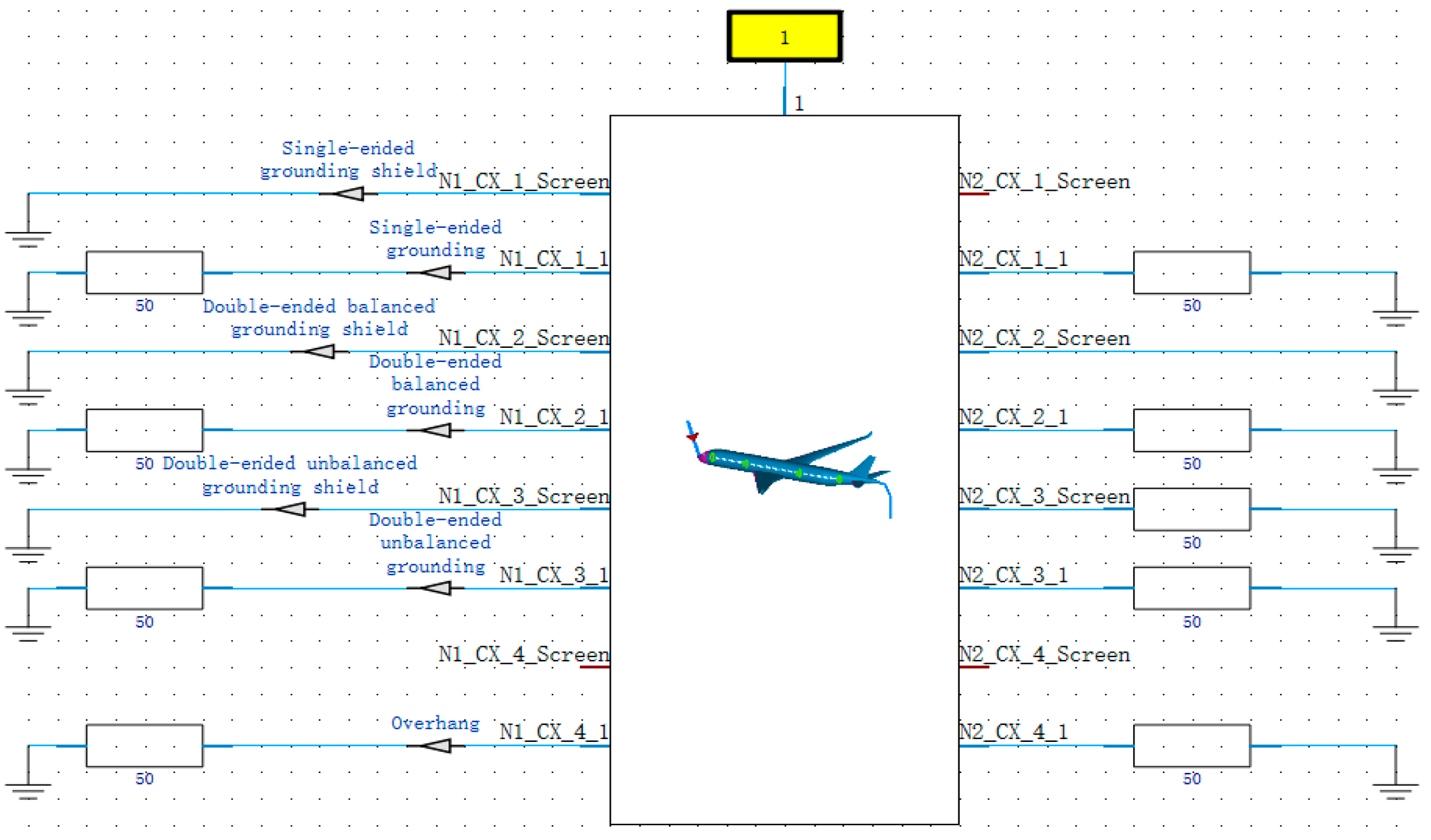
In addition to the material of the cable shielding layer, the grounding mode will also have an impact on the shielding performance. The grounding modes of the cable shielding layer shown in Figure 12 generally can be divided into four types as follows: single-ended grounding, double-ended balanced grounding, double-ended unbalanced grounding, and overhang.
According to the four different cable shield grounding methods, the shield grounding method comparison model was established, as shown in Figure 13.
The simulation model further analyzed the shield grounding methods, set up the above four shield grounding methods, and then measured and obtained the induced currents in the single-ended grounding, double-ended balanced grounding, double-ended unbalanced grounding, overhang of the core wire and the shield after the lightning injection. The peak value is shown in Table 5.
As shown in Table 5, different grounding modes of the shielding layer have a large impact on the shielding performance of the cable’s indirect effect. Among the four grounding modes, the best shielding performance is provided by the double-ended balanced grounding, and the weakest shielding performance is provided by the double-ended unbalanced grounding mode. Therefore, when laying cables inside composite aircraft, it is best to use cables with a shielding layer for the transmission of important signals or sensitive equipment cables, and the best choice of the shielding layer grounding mode is double-ended balanced grounding.

5. Principles of Laying Cables

5.1. Cable Layout

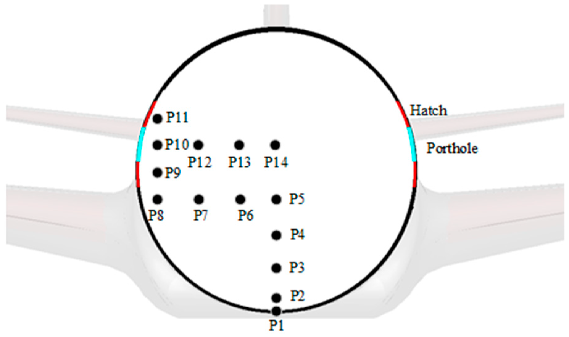
During the selection of the cable shielding layer inside the fuselage, one must consider the importance of the equipment, the type of transmission signal, the cable installation location, and working environment. The layout of the cables in the composite fuselage was analyzed to study its influence on shielding performance. Fourteen single wires were laid at different positions inside the composite aircraft fuselage, marked as P1-P14. The cables were parallel to the aircraft floor, with a longitudinal length of 9 m along the fuselage. The y-z section layout is shown in Figure 14.
For the comparison of the coupling of cables at different locations inside the cabin layout after the aircraft was struck by lightning, 14 cables were divided into the following four groups: cables P1-P5 formed group A, cables P5-P8 formed group B, cables P8-P11 formed group C, and cables P10 and P12-P14 formed group D.
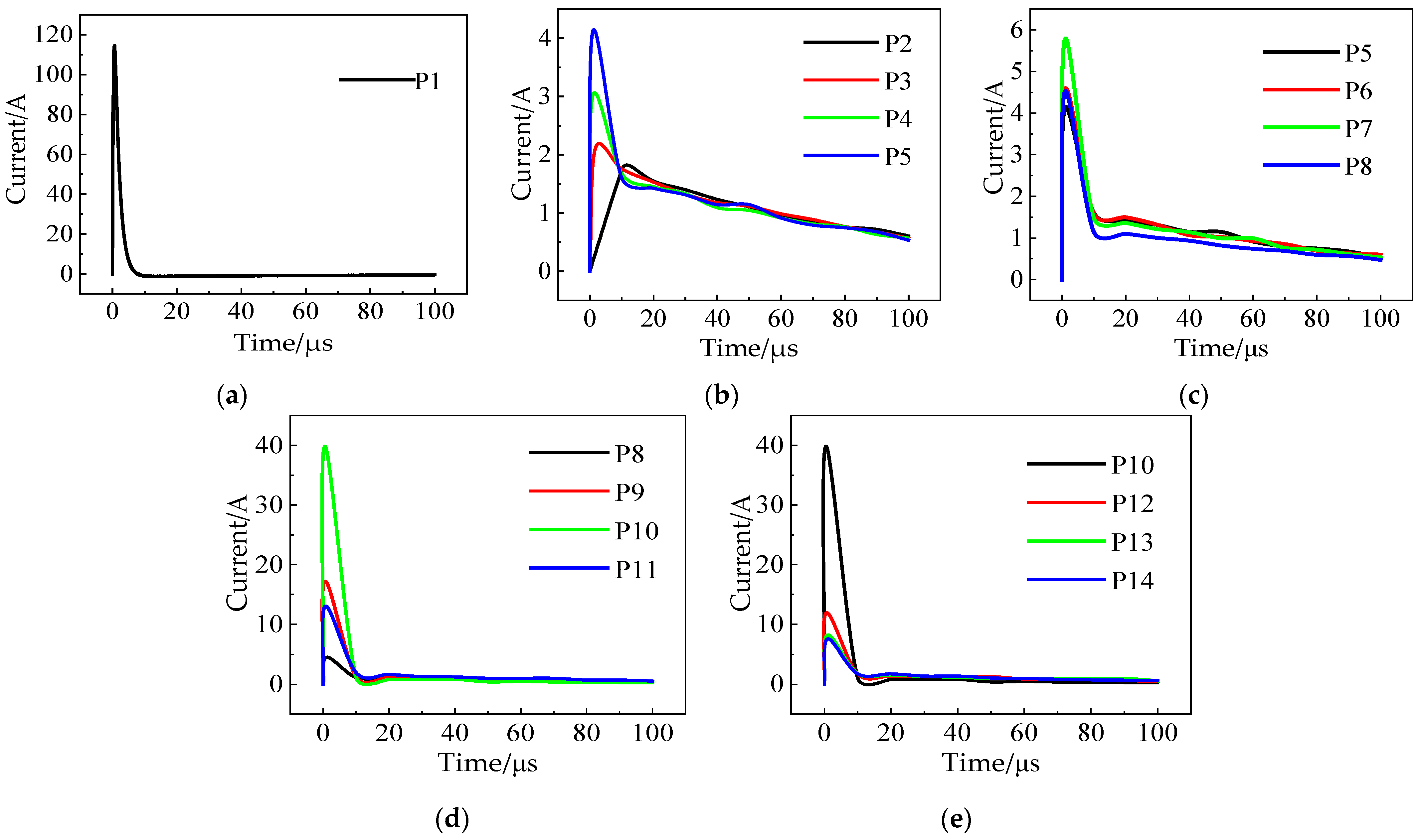
The calculation results of the induced current of the four groups of cables are shown in Figure 15, including P1 induced current of group A, P2-P4 induced current of group A, and the induced current of cables of groups B, C, and D. The grouping descriptions of the four groups of cables are shown in Table 6.
The four groups of cable induction currents were calculated, as shown in Figure 15.
In group A, the current of cable P1 is much larger than the cable induction current inside the aircraft because it is located on the aircraft surface. In addition, the closer the position of the internal cable of the composite aircraft is to the skin, the smaller its cable induced current, i.e., the higher the shielding performance of the lightning indirect effect. In group B, because of the proximity to the left side of the hatch, the closer the cable is to the skin, the higher the induction current, and the weaker the shielding performance. As the cable moves further form the aircraft skin, the induced current of the cable decreases gradually. This is because the electromagnetic leakage effect of the doors and windows on the cable is less than the shielding ability of the skin on the cable. In group C, as the cable moves from the hatch to the window, the induction current increases, and its shielding performance is weakened. However, as the cable close to the aircraft skin is moved further, the cable induction current gradually reduces. In group D, as the cable is moved away from the windows and doors, the cable induction current drops significantly, but compared with group B, the induction current of cables P12–P13 is still greater than cables P5–P8.
In summary, the cables laid on the surface of the aircraft skin should be reduced as much as possible, and attention should be paid to the connection between the cables on the skin surface and the interior. In addition, cables should not be arranged near the doors or windows of the fuselage. When cables must be arranged on the fuselage, the closer the cables are to the skin, the better. The shielding layer with good shielding performance must be selected.

5.2. Cable Track Groove

Cables should be arranged far away from the gap and close to the ground or structure to reduce the loop magnetic flux formed by cables and structures. In practice, cables are often laid in metal track grooves. Both the Current Return Network of B787 and the Electrical Structure Network and Metal Bonding Network of A350XWB contain a metal frame structure. Therefore, the cable track was set inside the composite aircraft fuselage, and the track model is shown in Figure 16.
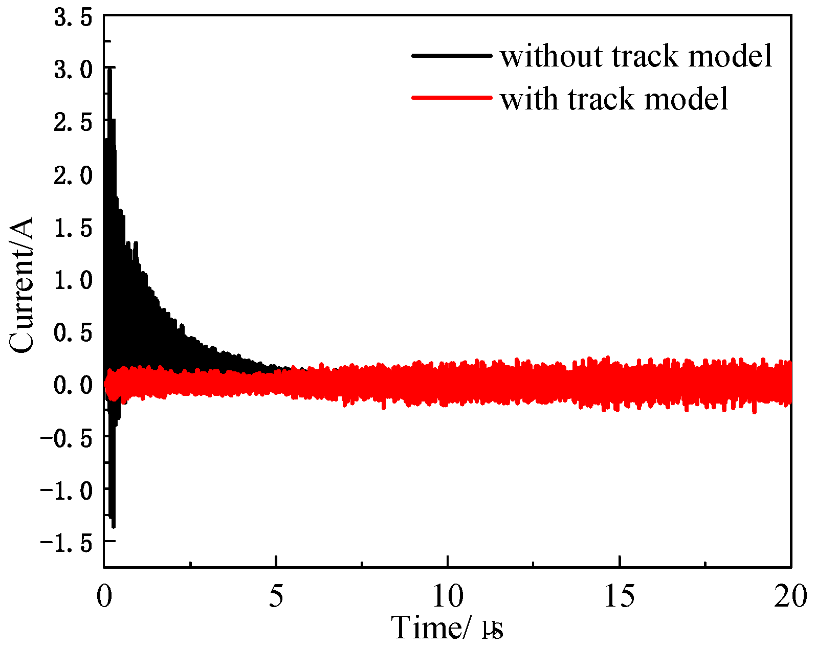
The influence of the track on a single wire was analyzed, and the cable induced current results are shown in Figure 17.
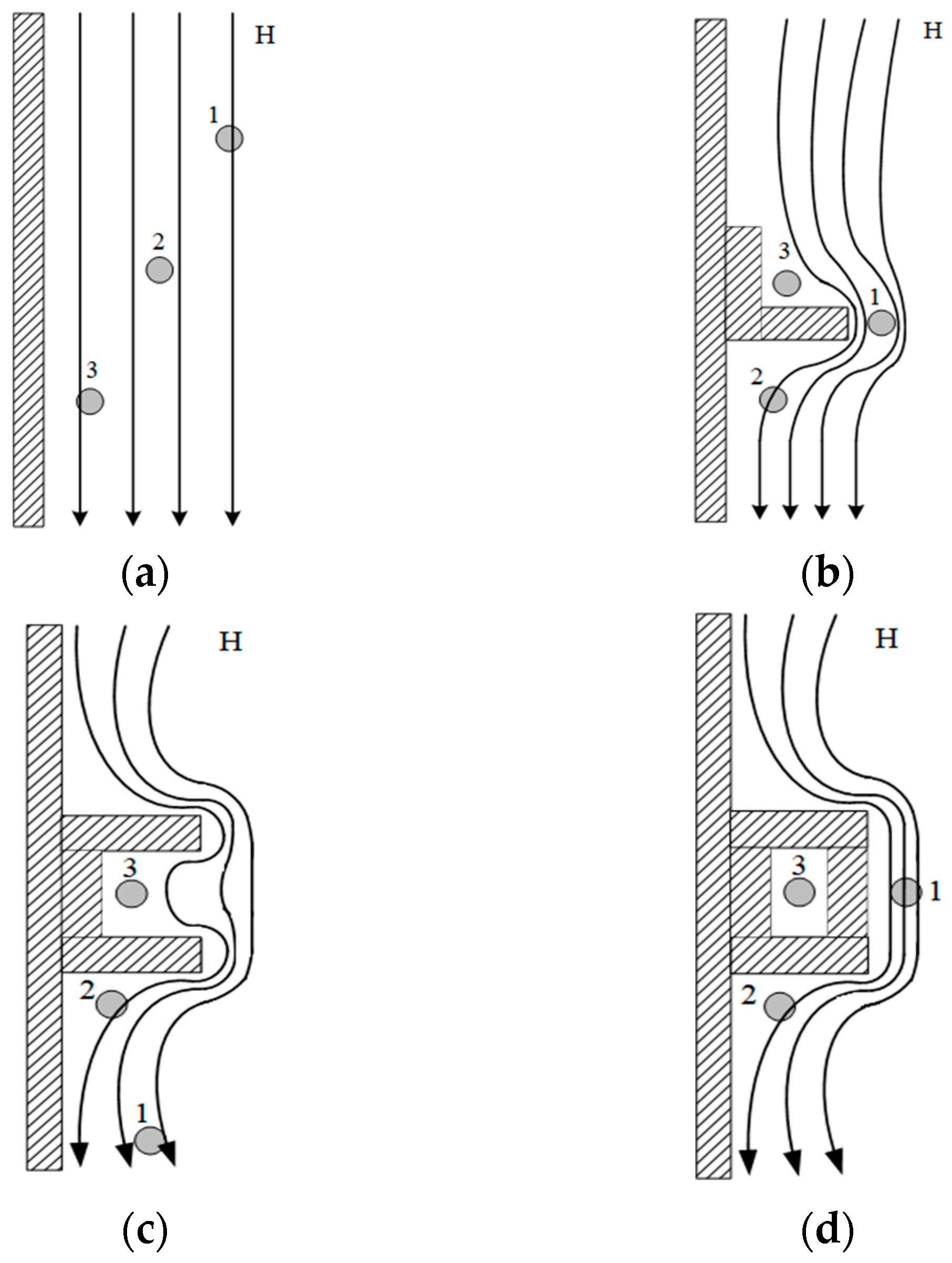
Based on the calculation, when the cable is laid inside the track, its induced current is much smaller than when there is no track, which verifies the shielding effect of metal track on the cable. To assist in analyzing the principle of laying cables inside the fuselage, the laying positions of the cables relative to the structural components are given in Figure 18, where cables 1–3 transmit current in their axial direction.
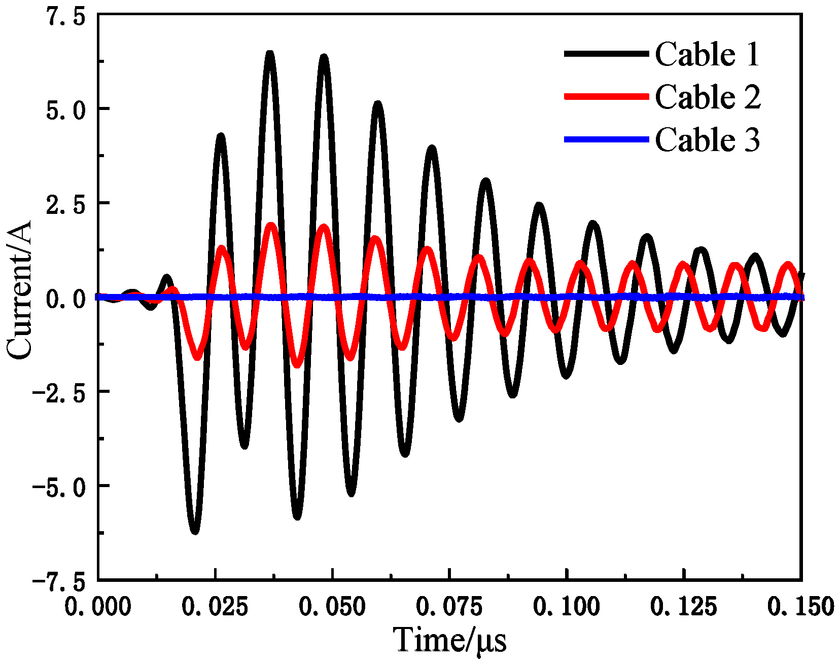
The shielding performance of the cables in the figure is from weak to strong, namely, cable 1, cable 2, and cable 3. Simulation verification was carried out using Figure 18d as an example to obtain the induced currents of the cables laid at different locations, as shown in Figure 19.
According to the “Boeing 787 Electrical System System & Component Description/Operation, and Maintenance Training Course”, the 28 VDC bus voltage fluctuation range is within 6 V. And according to ANSI/NEMA WC 27500 [25] and SAE AS22759 [26], the simulation cable impedance is 0.02016 Ω. The maximum peak current of cable 1 in Figure 19 is 6.41 A, and the interference voltage caused by the induced current is 0.12923 V. Therefore, it meets the corresponding airworthiness requirements. Meanwhile, the graph suggests that cable 3 has the best shielding performance and cable 1 has the worst shielding performance. This is because the magnetic field is concentrated at structures of greater curvature and dispersed at structures of lesser curvature. Based on this property, the magnetic flux through the loop of cable 1 is greater than the magnetic flux through cable 2. As cable 3 is shielded by a structural member or track recess, the magnetic flux through cable 3 is much less than the magnetic flux between cable 1 and cable 2.

6. Conclusions

This work investigates the indirect effect shielding performance of composite aircraft cable shielding measures by establishing an analytical model of aircraft cable shielding during lightning strikes. The various factors affecting shielding performance are considered, and the following conclusions are obtained:
(1) Based on the spatial electromagnetic field distribution after lightning injection into the aircraft model, the aircraft is prone to generating large electromagnetic fields at the nose, position, and fuselage. It is necessary to insulate the aircraft fuselage, such as at the porthole glass and the hatch, to reduce the electromagnetic interference of the backdoor coupling to the on-board equipment. At the same time, laying cables near doors, window openings, and protruding structures should be avoided as much as possible.
(2) In comparison with four different types of aircraft cables and different cable shield grounding methods, based on the analysis of the induced current after a lightning strike, it can be concluded that if the shielding performance of the aircraft internal cable needs to be enhanced, the corresponding shielding layer can be increased to meet the requirement, and the selection of the twisted-pair cable indirect effect is better than the other cables. The shielding performance can be significantly improved when the shielding layer and shielding layer double-ended have a balanced grounding. For the future development of electric aircraft, this can be selected for use in the aircraft electromagnetic exposure area or sensitive equipment with a shielding layer of a twisted pair or with a shielding layer suitable for cables. Based on the electric aircraft electrical structure network, the appropriate choice of shielding layer grounding to meet the ARP 1870 required bonding impedance is less than 2.5 mΩ to achieve a safer flight of electric aircraft.
(3) When a fuselage gap cannot be avoided, or needs to be close to the ground, the cable can be laid in a closed metal groove to reduce electromagnetic interference. This is an excellent way to reduce induced current and standardize cable routes for electric aircraft that require a large number of electrical cables to be connected and operated, greatly increasing the electrical safety of electric aircraft.

Author Contributions

Conceptualization, Z.Y. and X.S.; methodology, Z.Y.; software, Y.W.; validation, Y.W. and Z.Y.; formal analysis, Y.W.; investigation, Y.W.; resources, Z.Y.; data curation, Y.W.; writing—original draft preparation, Y.W.; writing—review and editing, Y.W.; visualization, Z.Y.; supervision, Z.Y.; project administration, Z.Y.; funding acquisition, Z.Y. All authors have read and agreed to the published version of the manuscript.

Funding

This research was funded by the Open Fund of Tianjin Aviation Equipment Safety and Airworthiness Technology Innovation Center, grant number JCZX-2023-KF-06.

Data Availability Statement

The data used to support the findings of this study are available from the corresponding author upon request.

Conflicts of Interest

The authors declare no conflicts of interest.

References

  1. Huang, Y.; Dan, S.; Danielle, S.S. Assessing the novel aircraft lightning strike protection technology using technology impact forecasting. J. Aircraft. 2020, 57, 914–921. [Google Scholar] [CrossRef]
  2. Teichmann, F.K. Chief Editorial Committee of Aircraft Design Manual. In Aircraft Design Manual; Aviation Industry Press: Beijing, China, 2000; Volume 10. [Google Scholar]
  3. Cai, L.; Du, Y.; Wang, J.; Zhou, M.; Chu, W.; Xu, C.; Fan, Y. Development characteristics of triggered lightning with fast initial continuous current pulses and two grounding points. Atmos. Res. 2023, 283, 106587. [Google Scholar] [CrossRef]
  4. Duan, Z.M. Review of aircraft lightning protection. High Volt. Eng. 2017, 43, 1393–1399. [Google Scholar] [CrossRef]
  5. Lloyd, K.J.; Plumer, J.A.; Walko, L.C. Measurement and analysis of lightning-induced voltages in aircraft electrical circuits. In NASA Contractor Report CR-1744; Lightning Technologies Inc.: Pittsfield, MA, USA, 1971. [Google Scholar] [CrossRef]
  6. Fisher, F.A.; Plumer, A.; Perala, R.A. Aircraft Lightning Protection Handbook; National Technical Information Service: Springfield, CA, USA, 2004.
  7. Zhao, T.; Chen, Y.; Xu, W.; Duan, Y.; Wang, Z.; Wang, N. Research on Multi-physical field simulation modeling of nacelle CFRP-metal structure by lightning strike. In Proceedings of the 2023 6th International Conference on Energy, Electrical and Power Engineering (CEEPE), Guangzhou, China, 12–14 May 2023; pp. 211–219. [Google Scholar] [CrossRef]
  8. Wang, B.; Zhang, Y.; Peng, M.; Lv, X.; Zhang, S.; Zhang, Z. A Study of Measuring Indirect Effects of Lightning on Commercial Aircraft Engine Control Systems. In Proceedings of the 2023 IEEE International Workshop on Electromagnetics: Applications and Student Innovation Competition (iWEM), Harbin, China, 15–18 July 2023; pp. 179–184. [Google Scholar] [CrossRef]
  9. Wang, Y.; Liang, X.; Dai, J.; Wang, L. Indirect Effects of Lightning Electromagnetic Environment Evaluation Analysis Method for Civil Aircraft. In Proceedings of the 2023 9th International Conference on Electrical Engineering, Control and Robotics (EECR), Wuhan, China, 24–26 February 2023; pp. 100–103. [Google Scholar] [CrossRef]
  10. Kowalczuk, E. Exploring Lightning Susceptibility of Composite Materials and Cable Harnesses in Aircraft through Electromagnetic Simulation; IET Seminar on Lightning Protection for Aircraft Components: Abingdon, UK, 2013; pp. 1–26. [Google Scholar] [CrossRef]
  11. Perrin, E.; Tristant, F.; Guiffaut, C.; Reineix, A. A numerical tool to estimate lightning indirect effects on a composite aircraft. In Proceedings of the 2010 30th International Conference on Lightning Protection (ICLP), Cagliari, Italy, 13–17 September 2010; pp. 1–4. [Google Scholar] [CrossRef]
  12. Aguilera, P.; Lair, C.; Issac, F.; Michielsen, B. A reciprocity approach to the indirect effects of lightning impact on an aircraft engine. In Proceedings of the 2016 International Symposium on Electromagnetic Compatibility—EMC EUROPE, Wroclaw, Poland, 5–9 September 2016; pp. 343–346. [Google Scholar] [CrossRef]
  13. Gao, R.X.-K.; Lee, H.M.; Ewe, W.B.; Tay, S.W.; Thitsartarn, W.; Yang, Z.; Mahmoudi, M.; Juanda, E.; Kohler, J.; Wang, W. Electromagnetic characterization and measurement of conductive aircraft CFRP composite for lightning protection and EMI shielding. IEEE Trans. Instrum. Meas. 2023, 72, 6011611. [Google Scholar] [CrossRef]
  14. Zampolli, Y.G.; Prado, A.J.D. Effect and behavior of lightning on composite material structures used in aircraft. In Proceedings of the 2022 International Conference on Electromagnetics in Advanced Applications (ICEAA), Cape Town, South Africa, 5–9 September 2022; pp. 264–266. [Google Scholar] [CrossRef]
  15. Wang, S.M.; Chen, X.-N.; Guo, F.; Huang, L.-Y. Lightning indirect effects on UH-1H helicopter: Numerical simulation analysis and EM shielding. In Proceedings of the 2017 IEEE 5th International Symposium on Electromagnetic Compatibility (EMC-Beijing), Beijing, China, 28–31 October 2017; pp. 1–4. [Google Scholar]
  16. Langot, J.; Gourcerol, E.; Serbescu, A.; Brassard, D.; Chizari, K.; Lapalme, M.; Desautels, A.; Sirois, F.; Therriault, D. Performance of painted and non-painted non-woven nickel-coated carbon fibers for lightning strike protection of composite aircraft. Compos. Part A Appl. Sci. Manuf. 2023, 175, 107772. [Google Scholar] [CrossRef]
  17. Piche, A.; Perraud, R.; Urrea, O.; Haddad, S. Coupling analysis of aircraft raceways. In Proceedings of the International Symposium on Electromagnetic Compatibility—EMC EUROPE, Rome, Italy, 17–21 September 2012; pp. 1–6. [Google Scholar] [CrossRef]
  18. Jo, J.; Kim, Y.; Kim, D.; Lee, H.; Myong, R.S. Effect of shielding and drain wire on lightning-induced currents in rotorcraft cables. IEEE Trans. Electromagn. Compat. 2022, 64, 2015–2023. [Google Scholar] [CrossRef]
  19. Lu, C. More about lightning induced effects on systems in a composite aircraft. In Multidisciplinary Design Analysis and Optimization of Aerospace Composites; SAE: Warrendale, PA, USA, 2020; pp. 151–162. [Google Scholar] [CrossRef]
  20. MIL-STD-464D; Electromagnetic Environmental Effects Requirements for System. Department of Defense Interface Standard: Washington, DC, USA, 2020.
  21. Jones, C.E.; Norman, P.J.; Burt, G.M.; Hill, C.; Allegri, G.; Yon, J.M.; Hamerton, I.; Trask, R.S. A route to sustainable aviation: A roadmap for the realization of aircraft components with electrical and structural multifunctionality. IEEE Trans. Transp. Electrif. 2021, 7, 3032–3049. [Google Scholar] [CrossRef]
  22. Yang, Z.G.; Zhang, Q.; Sui, Z.; Shi, X. Impedance analysis of current return networks in composite aircraft based on partial element equivalent circuit. Electron. Lett. 2021, 57, 842–844. [Google Scholar] [CrossRef]
  23. Zhou, Q.H.; Wu, H.L. Research on Shielding of Composite Aircraft. In Proceedings of the 2018 International Academic conference for graduates NUAA, Nanjing, China, 17–19 October 2018; Volume A1, pp. 49–53. [Google Scholar]
  24. Shan, Z.; Tian, M.; Lu, X. Analysis of lightning ablation damage performance of glass fiber reinforced polymer materials. J. Braz. Soc. Mech. Sci. Eng. 2021, 44, 22. [Google Scholar] [CrossRef]
  25. ANSI/NEMA WC 27500; Aerospace and Industrial Electrical Cable. National Electrical Manufacturers Association: Rosslyn, VA, USA, 2020.
  26. SAE AS22759; Wire, Electrical, Fluoropolymer-Insulated, Copper or Copper Alloy. Society of Automotive Engineers: Washington, DC, USA, 2018.
Figure 1. Coupling mechanism between lightning and an aircraft.
Aerospace 11 00674 g001
Figure 2. The second step in the composite aircraft coupling process.
Aerospace 11 00674 g002
Figure 3. Aircraft after laying metal mesh on the composite aircraft fuselage.
Aerospace 11 00674 g003
Figure 4. Composite aircraft model diagram.
Aerospace 11 00674 g004
Figure 5. Waveform of the A component of the lightning current.
Aerospace 11 00674 g005
Figure 6. Aircraft internal cable segmentation.
Aerospace 11 00674 g006
Figure 7. Spatial electromagnetic field distribution after a lightning strike on a composite aircraft: (a) electric field distribution in space and (b) space magnetic field distribution.
Aerospace 11 00674 g007
Figure 8. Electromagnetic interference from portholes and hatches. (a) Airframe space electric field equivalent situation. (b) Airframe space magnetic field equivalent situation.
Aerospace 11 00674 g008
Figure 9. Different types of cables in aircraft: (a) a single wire; (b) a coaxial wire with a shielding layer; (c) a twisted pair; (d) a twisted pair with a shielding layer.
Aerospace 11 00674 g009
Figure 10. Simulation model for different types of cable shielding analyses.
Aerospace 11 00674 g010
Figure 11. Description of the cable metal braid shielding layer.
Aerospace 11 00674 g011
Figure 12. Grounding modes: (a) single-ended grounding; (b) double-ended balanced grounding; (c) double-ended unbalanced grounding; and (d) overhang.
Aerospace 11 00674 g012
Figure 13. Comparison of grounding methods for cable shields.
Aerospace 11 00674 g013
Figure 14. Cable layout inside the composite aircraft fuselage.
Aerospace 11 00674 g014
Figure 15. Induced current of cables at different positions: (a) P1 induction current; (b) P2–P5 induction current; (c) P5–P8 induction current; (d) P8–P11 induction current; and (e) P10–P14 induction current.
Aerospace 11 00674 g015
Figure 16. The U-shaped single-track groove.
Aerospace 11 00674 g016
Figure 17. Influence of the track on the induced current of the cable.
Aerospace 11 00674 g017
Figure 18. The cable position relative to the structural components: (a) plane; (b) angle; (c) groove; (d) enclosed structure.
Aerospace 11 00674 g018
Figure 19. Induced current of cables at different positions.
Aerospace 11 00674 g019
Table 1. Aircraft material conductivity.
Material AluminumGlass CFRP
xyz
Conductivity (S/m)3.56 × 1071 × 10−1240,4902001.3
Table 2. Calculation results of the indirect effect of lightning on the aircraft.
MaterialPeak Value of Internal Magnetic Field Intensity (A/m)Cable Induced Current Peak (A)
Core of WireShield of Wire
Aluminum59.3842.912229.597
CFRP891.6536.3468667.492
CFRP combined with metal mesh531.6682.9562687.860
Table 3. Induced current peak value of different types of cables.
TypesSingle WireCoaxial Wire with Shielding LayerTwisted PairTwisted Pair with Shielding Layer
Induced current peak value (A)1.88440.05942.4498 × 10−53.3452 × 10⁻⁶
Table 4. Influence of cable shielding material.
MaterialCable Induced Current Peak (A)
Core of WireShield of Wire
No shielding layer1.8844——
Copper0.0118184.1521
Silver0.0106200.1759
Aluminum0.0169120.1643
Table 5. Influence of grounding modes.
Grounding ModesCable Induced Current Peak (A)
Core of WireShield of Wire
Single-ended grounding1.46142.1997
Double-ended balanced grounding0.2923405.1898
Double-ended unbalanced grounding1.56984.6978
Overhang1.2709——
Table 6. Grouping descriptions of cables.
GroupsMarkDistanceMain Method of Electromagnetic Energy Coupling
AP1, P2–P50.4 mBottom skin
BP5–P80.43 mLeft skin and hatch door
CP8–P110.3 mHatch door and porthole
DP10, P12–P140.43 mLeft skin and porthole
Disclaimer/Publisher’s Note: The statements, opinions and data contained in all publications are solely those of the individual author(s) and contributor(s) and not of MDPI and/or the editor(s). MDPI and/or the editor(s) disclaim responsibility for any injury to people or property resulting from any ideas, methods, instructions or products referred to in the content.