Article

Optimal Design of High-Power Density Medium-Voltage Direct Current Bipolar Power Cables for Lunar Power Transmission

Zero Emission, Realization of Optimized Energy Systems (ZEROES) Laboratory, Department of Electrical and Computer Engineering, The University of Texas at Dallas, Richardson, TX 75080, USA
*
Author to whom correspondence should be addressed.
Aerospace 2024, 11(8), 685; https://doi.org/10.3390/aerospace11080685
Submission received: 21 July 2024 / Revised: 11 August 2024 / Accepted: 19 August 2024 / Published: 20 August 2024
(This article belongs to the Section Astronautics & Space Science)

Abstract

:
Power systems on the lunar surface require power lines of varying lengths and capacities to connect generation, storage, and load facilities. These lines must be designed to perform efficiently in the harsh lunar environment, considering factors such as weight, volume, safety, cost-effectiveness, and reliability. Traditional power transmission methods face challenges in this environment due to temperature fluctuations, micrometeoroid impacts, and ionizing radiation. Underground deployment, although generally safer, faces challenges due to low soil thermal conductivity. At a depth of 30 cm, the lunar temperature of −23.15 °C can be advantageous for managing waste heat. This study presents a novel approach, developed using COMSOL Multiphysics, for designing bipolar MVDC cables for lunar subsurface power transmission. Kapton® MT+ is chosen as the insulating material for its exceptional properties, including high thermal conductivity and superior dielectric strength. The cables are designed for voltages of ±10 kV and ±5 kV and capacities of 200 kW (low power), 1 MW (medium power), and 2 MW (high power). Our findings indicate that aluminum conductors offer superior performance compared to copper at medium and high power levels. Additionally, elevated voltage levels (±10 kV) enhance cable design and power transfer efficiency. These specially designed cables are well-suited for efficient operation in the challenging lunar environment.

1. Introduction

As lunar exploration ambitions rise, the demand for surface power is expected to reach megawatt (MW) levels. The increasing demand is a result of the increased involvement of public and private entities in lunar exploration projects. NASA aims to create a sustainable human presence on the moon, necessitating advanced and reliable surface power systems. These systems are crucial for sustaining a long-term presence on the moon, supporting human activities, enabling research efforts, and powering vital technological activities [1,2,3]. To enable efficient power distribution across different lunar sites, a lunar-based power system may necessitate a network of interconnected power lines with varying lengths and capacities. This infrastructure would facilitate the transfer of energy between different types and sizes of power generation sources, energy storage facilities, and loads situated across the lunar surface. Designing power lines with high power density involves significant challenges, especially in terms of weight and volume constraints. Therefore, priority should be placed on addressing safety, cost-effectiveness, and reliability concerns in the harsh lunar environment while ensuring that these power cables meet the necessary criteria. This includes considerations such as robust insulation to withstand extreme temperatures and radiation, as well as efficient heat dissipation mechanisms. Additionally, the design should incorporate lightweight materials and compact configurations to minimize payload requirements for transportation to the moon. Overall, a balanced approach is essential to ensuring the successful deployment and operation of power lines on the lunar surface.
Operating electrical power systems on the moon presents numerous challenging problems, including managing lunar surface temperatures and thermal radiation, mitigating micrometeoroid bombardment, addressing gaseous contamination, adapting to vacuum conditions allowing solar thermal radiation input, accommodating night and day cycles, and controlling ionizing radiation [4]. Overcoming these challenges within the lunar environment is paramount for the successful operation of the lunar power system. To minimize resistive losses, reduce conductor weight, and improve thermal management, it is preferable to use higher voltages rather than increasing currents in power distribution systems. Additionally, DC is favored over AC due to its lower power loss. In this regard, medium-voltage direct current (MVDC) cables play a crucial role in lunar power systems. MVDC technology enables the efficient transmission of electricity at higher voltages, facilitating the management of energy distribution within lunar infrastructure amidst the challenges posed by lunar circumstances. The integration of MVDC cables enhances the reliability and sustainability of the lunar power grid, thereby contributing to the success of lunar exploration and habitation missions.
The ampacity of insulated cables can be determined using IEC standards like IEC 60287 [5], which provides formulas for current ratings under steady-state conditions but lacks heat transfer equations for temperature evolution. Similarly, IEC 60853 [6] covers cyclic and emergency current ratings without addressing temperature changes over time, while IEC 60986 [7] offers permissible short-circuit temperatures based on limited experimental data, without detailing temperature evolution [5,6,7]. The IEC TR 62095 [8] standard emphasizes the use of finite element analysis (FEA) methods for current rating calculations of power cables, particularly when traditional methods from IEC 60287 and IEC 60853 are inadequate. FEA is recognized for its powerful and realistic approach to determining the electromagnetic and thermal performance of power cables, offering detailed insights into temperature distribution and heat dissipation [8].
This study presents the development and application of an integrated electrical and thermal model elaborated in COMSOL Multiphysics to design and analyze coaxial bipolar MVDC power cables, assessing their suitability for lunar conditions. The model can calculate temperature and electric fields for coaxial bipolar cable systems. The findings provide valuable insights for developing MVDC power connections that can operate effectively in the challenging lunar environment.

2. Challenges Related to the Lunar Environment

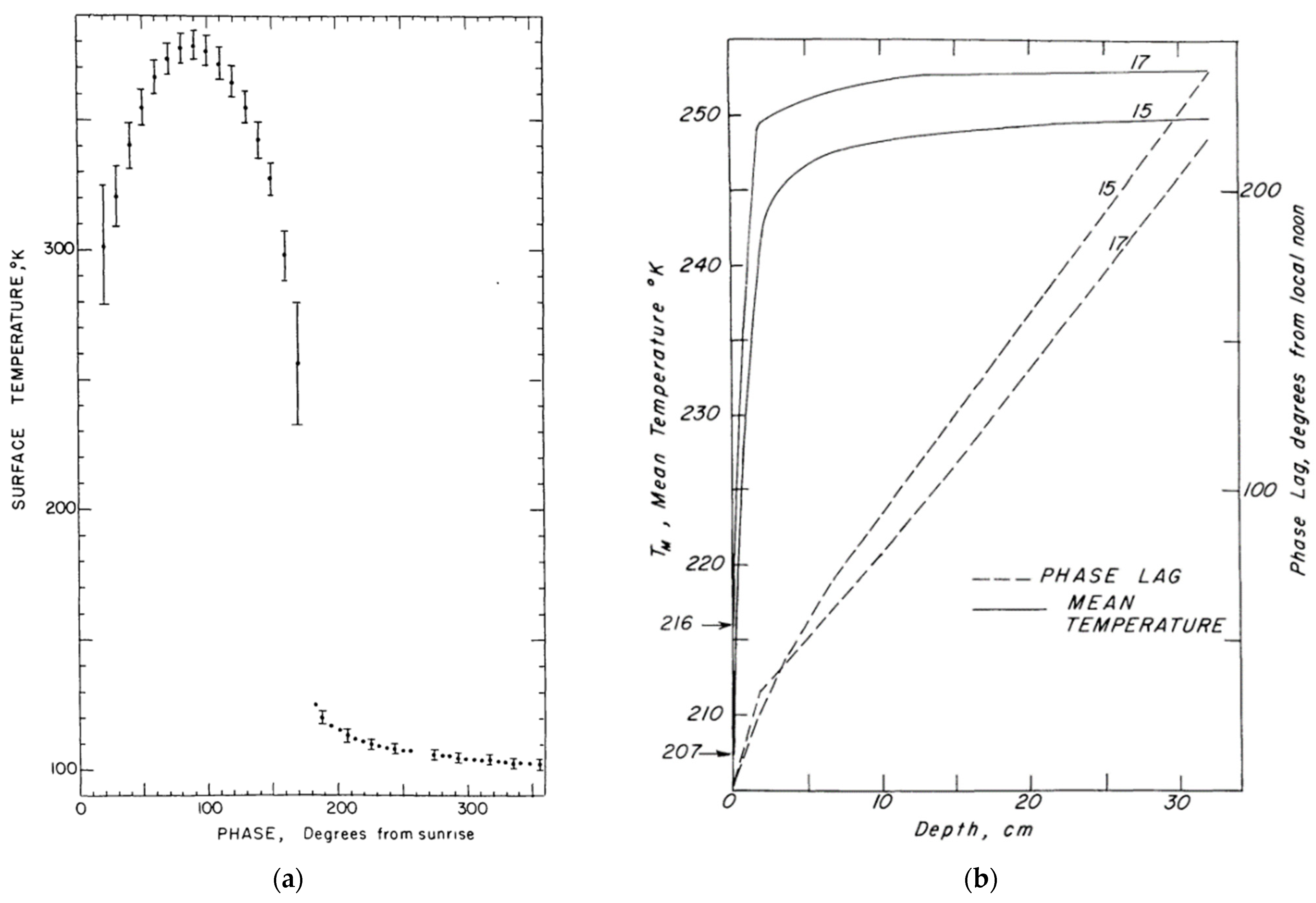
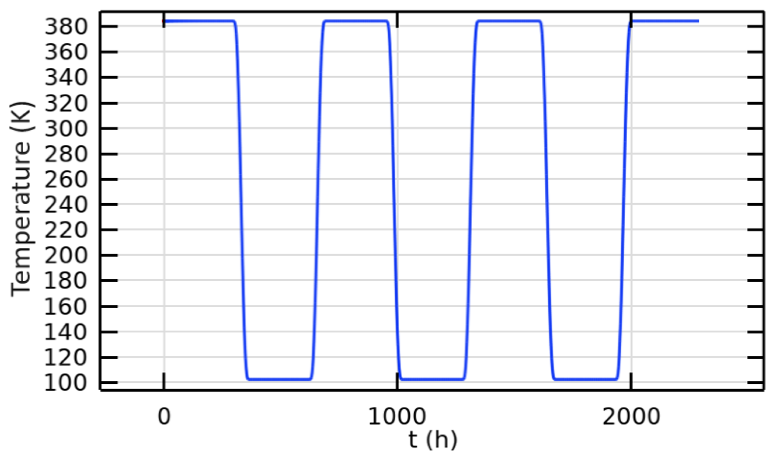
2.1. The Lunar Environment

The atmospheric pressure on the moon varies from around 10−8 torr during the day to 10−12 torr at night [9,10,11]. The diffusive and sputter release of implanted solar wind noble gases, vaporization from meteorites and comet impacts, spacecraft contamination nearby, and small contributions from gas venting or degassing from impact events are some of the sources of this insubstantial atmosphere [9,12,13]. A lack of atmosphere has both positive and negative effects on cables. In the absence of an atmosphere, there are no pollutants that chemically degrade materials. However, this absence also means there is no natural shield against cosmic and solar radiation or micrometeorites, all of which are typically attenuated by the earth’s atmosphere before reaching the surface. The sun’s intensity on the lunar surface is the same as it is everywhere else in the earth’s orbit, as there is essentially no atmosphere on the moon. The energy flux from the sun to the moon is measured at 1371 ± 5 W/m2 [9]. Galactic cosmic rays and charged particles from the solar wind may easily reach the moon’s surface due to its weak magnetic field. Dielectric materials can suffer significant deterioration from solar radiation, particularly UV radiation.
Lunar power line design considers key properties of the lunar soil, particularly its electrical and thermal characteristics. Particle size plays a crucial role, as the potential electrostatic charge of lunar dust particles may exacerbate electrical breakdown. For DC transmission, the primary electrical properties of interest are DC conductivity and dielectric strength. Typically, the upper layers of the lunar surface exhibit DC conductivity values ranging from 10−13 to 10−16 S/m [14]. These properties of lunar soil are essential when employing bare conductors for power transmission beneath the lunar surface. However, deploying bare bipolar MVDC conductors poses safety risks for astronauts who may be involved in soil excavation during missions. In this scenario, using solid insulation around the core conductor is a viable solution. The two critical thermal properties to evaluate are the subsurface temperature profile and the thermal conductivity of the surrounding soil. As seen in Figure 1a, the temperature on the lunar surface fluctuates significantly, ranging from 110.85 °C (384 K) during the day to −171.1 °C (102 K) at dawn. As seen in Figure 1b, this temperature swing decreases rapidly with depth; at 30 cm depth, it stabilizes around −23.15 °C, making it suitable for sub-surface applications [15,16]. The thermal conductivity of the soil is approximately 1.5 × 10⁻⁵ W/(cm·K) at depths of 2 cm or less, increasing to 1.0–1.5 × 10⁻⁴ W/(cm·K) from 2 to 15 cm. The upper 2 cm consists of porous, low-conductivity material, with radiative heat transfer dominating over conductive heat transfer to the surrounding soil [15].

2.2. Specifications of Power Lines

Two main types of power transmission are AC and DC. DC is known for having the lowest line losses. This paper will focus on bipolar DC power lines. There are three possible places for power lines to be on the lunar surface, as follows: (1) above the surface, (2) on the surface itself, or (3) below the surface. In the above-the-surface approach, insulators are necessary to protect the bare conductors, and the transmission line conductors need to be suspended from support structures such as poles.
Sufficient space between the lunar surface and the line is crucial to allow for both unimpeded heat radiation and safe passage for vehicles or people underneath. When comparing methods, it is essential to consider the additional masses of the supporting poles, which are not required for on-the-surface or below-the-surface distribution. Radiation serves as the sole method for dissipating power loss in a vacuum. Another significant limitation with above-the-surface conductors is the risk of exceeding their elastic limit. Temperature fluctuations affect conductor sag between towers, leading to a decrease in tensile strength due to annealing. Excessive temperatures may cause the conductor to surpass its elastic limit, preventing it from returning to its original length upon cooling.
Conductor manufacturers provide approximate current-carrying capacities based on specific conditions, typically assuming the conductor is at 75 °C, the surrounding air at 25 °C, and the wind speed at 2 ft/s [17]. However, estimates from [2] suggest that for an above-the-surface option, conductor temperatures for aluminum (Al) and copper (Cu) reach 76 °C and 81 °C, respectively, for a 10 kV DC, 100 kW line (low power). For an 800 kW power transmission, the conductor temperature for Al rises to 287 °C, making the above-the-surface method impractical. Moreover, towers and insulators required for the above-the-surface option pose technical challenges in the lunar environment. The moon faces bombardment from meteoroids and micrometeoroids weighing from 10−12 g to several hundred kilograms, traveling at velocities ranging from 2.4 to 72 km/s [18,19,20].
Electromagnetic interference (EMI) on the moon can result from both natural and human-made sources. EMI can arise from natural sources such as solar radiation, which emits a wide range of electromagnetic waves, and cosmic rays, which produce high-energy particles that can cause interference. In addition, the solar wind’s interaction with the lunar surface can generate low-frequency electromagnetic noise. EMI can also be generated by human-made sources, including communication systems, power systems, and electronic devices found in spacecraft and future lunar habitats. EMI shielding is crucial for DC power cables to protect against external interference, ensuring stable power delivery. To prevent any potential EMI, it is crucial to apply copper shielding uniformly and without any gaps. Ensuring proper grounding at both ends of the cable and strategically installing filters can effectively mitigate any remaining EMI.
Deploying the laying-on-the-surface method is advantageous because of its ease of use. However, it is crucial to consider Lorentz forces to avoid any displacement of the lines. Moreover, precautions must be taken to prevent damage to the lines and guarantee the safety of astronauts. Deploying below the surface is the safest and most convenient approach, despite the soil’s restricted thermal conductivity, which presents potential obstacles. A depth of 30 cm with a temperature of −23.15 °C can be beneficial for heat dissipation.
Experimental studies in [21,22] have demonstrated that simulated lunar soil under a pressure of 10−7 Pa serves as a reliable insulator. Unlike solid dielectrics, it maintains its electrical insulation characteristics consistently during breakdown tests. This suggests that incorporating bare conductors into lunar soil could offer a low-mass solution for power transmission. However, deploying bare bipolar HVDC conductors with a few centimeters of separation at a depth of several tens of centimeters presents safety concerns for astronauts involved in soil excavation during missions. This safety issue persists of course with surface-level operations. Due to the lack of or restricted availability of medical facilities on the lunar surface, it is crucial that all systems emphasize maximum safety.

3. Model and Design

3.1. Coupled Electrothermal Model

In this study, a comprehensive coupled electrothermal model is developed in COMSOL Multiphysics software 6.1 to examine the temperature and electric field distributions along the cables. The model incorporates heat transfer, electric current, and magnetic field modules to precisely evaluate the properties of the cables. This simulation only accounts for conductive heat transfer, as the cable is positioned beneath 30 cm of the lunar surface. Also, we have not considered pressure fluctuations in our simulation. We have also assumed that micrometeoroid bombardment, being less impactful at this depth, does not significantly affect the cable. Additionally, the lunar environment poses risks from charged particles, including solar wind, solar energetic particles (SEPs), and galactic cosmic rays (GCRs) [23,24]. Data from [24] indicate that while solar wind and SEPs penetrate only a few millimeters to centimeters of lunar soil, GCRs can penetrate deeper, up to a few meters. We assumed that the cable’s 30 cm depth protects it from the significant effects of solar wind and SEPs, but GCRs could potentially impact the cable. However, the specific impact of these charged particles on the cable’s performance remains uncertain and warrants further investigation. Consequently, our insulation design does not currently address deep dielectric charging.
Figure 2 illustrates the configuration of the coaxial bipolar cable. At 30 cm depth, the temperature is −23.15 °C. To maintain consistency, we have assigned the same temperature of −23.15 °C to the lower part of the simulated area located 5 cm below the lower part of the cable, as depicted in Figure 2. Meanwhile, the lunar surface temperature varies with the lunar day–night cycle.
It takes the moon the equivalent of 27.3 Earth days, or 655.2 h, to complete a single rotation on its axis, the same amount of time it takes to complete a single orbit around Earth. Temperature fluctuations on the lunar surface range from 110.85 °C in daylight to −171.1 °C at night. In this simulation, the daytime upper soil temperature remains at 110.85 °C for the first 327.6 h, followed by a nighttime temperature of −171.1 °C for the next 327.6 h. The simulation lasts for 2000 h to accurately assess the impacts of day and night cycles. The day–night cycle persists steadily until the simulation ends. A piecewise function is used to adjust the temperature of the upper part of the soil. Figure 3 illustrates the upper soil temperature plot over the simulation period. Throughout all simulations, the thermal conductivity of lunar soil remains constant at 1.0 × 10⁻⁴ W/(cm·K).
We have used extremely fine mesh in our study. The complete mesh comprised 19,866 vertices and 39,474 triangular elements, with additional edge and vertex elements numbering 2180 and 28, respectively. Figure 4 shows a close-up view of the mesh around the cable systems. The results remain consistent when using a denser mesh. The results are not affected by the size of the mesh used.
Heat transfer from the core conductor to the cable surface occurs solely through conduction. The heat equation describing the transfer within the cable, from its inner conductor to its outer jacket, can be expressed as follows:
ρ C p T t + · k T = Q s
where T is the temperature (K), k is thermal conductivity (W·(K·m)−1), ρ is the density (kg·m−3), C p is the specific heat capacity at the constant pressure (J·(kg·K)−1), and Q s represents the rate of heat generation per unit volume within the material. The heat generated due to Joule losses Q and the relation between Q s and Q can be defined as follows:
Q s = Q / V
Q = I 2 R
where V denotes the volume of the material (m3), I denotes the conductor current (A) and R denotes the resistance (Ω). Conductor losses ( Q ) are calculated under the coil node within the “Magnetic Fields” physics module of COMSOL. The coil node can be used to model coils, cables, and other conductors subject to a lumped excitation, such as an externally applied current or voltage. The linear resistivity ( ρ e ) of the coil is provided as follows:
ρ e = ρ 0 ( 1 + α ( T C T r e f )
where α is the resistivity temperature coefficient (K−1), T r e f represents the reference temperature (K), T C is the conductor temperature (K), and ρ 0 denotes the electric resistivity (Ω·m) at the reference temperature.
The conductivity of polymeric DC cables plays a crucial role in estimating the electric field. It is dependent on factors such as the temperature field, the electric field, and the properties of the insulating material. Equation (5) can be employed to express the DC conductivity of polymers, as follows:
σ E , T = σ 0 e a T + b E
where a   and b are the coefficients of temperature and electric field, respectively, E represents the electric field (V·m−1), and σ 0 is a constant regarding polymeric material. Due to the lack of specific data for the conductivity of Kapton® MT+ and Teflon® PFA, we have considered Kapton® MT+ as a polyimide (PI) material and Teflon® PFA as an ethylene-tetrafluoroethylene (ETFE) material. The electrical conductivity of PI and ETFE has been determined through curve fitting of the data from [25]. Table 1 presents the electrical conductivity parameters of Equation (5). The electric field distribution across the cable insulation can be acquired using the following equations:
E = V
J e = σ E
where σ represents the conductivity (S·m−1), V represents the voltage (V), and J e represents the current density (A·m−2). Moreover, the steady-state space charge density can be calculated using the following equation:
σ E · ε e σ = ρ e
where ε e represents permittivity and ρ e represents space charge density. The electric field and temperature field are interconnected, as shown in Equations (1)–(8). This paper presents a multi-physics model that uses the previously mentioned equations to calculate the ideal weight and dimensions of the cable needed to transmit a specified power level at two different voltage levels.
To ensure that the inner and outer conductors of coaxial bipolar cable systems have the same cross-sectional area, the following formula is utilized:
r c o n 1 2 = r c o n 3 2 r c o n 2 2
where r c o n 1 represents the radius of the inner conductor, r c o n 2 represents the radius of the inner section of the outer conductor, and r c o n 3 denotes the radius of the outer section of the outer conductor. In optimizing the design of power cables to reduce weight and overall cross-sectional area, the parameter J can be defined as follows:
J = m · A
where m represents the cable’s weight per unit length (kg·m−1) and A is its entire cross-sectional area (m2). The smaller J , the better the design, indicating a preference for high power density and minimal system mass needs. The electrical and thermal limits considered for the insulation materials of the cable are as follows:
E m a x < 0.2 E b d
T m a x < T l i m i t
where E b d and E m a x represent the breakdown strength and maximum electric field of the dielectric layer, respectively, and T m a x and T l i m i t are the maximum and allowable temperatures of the materials, respectively.

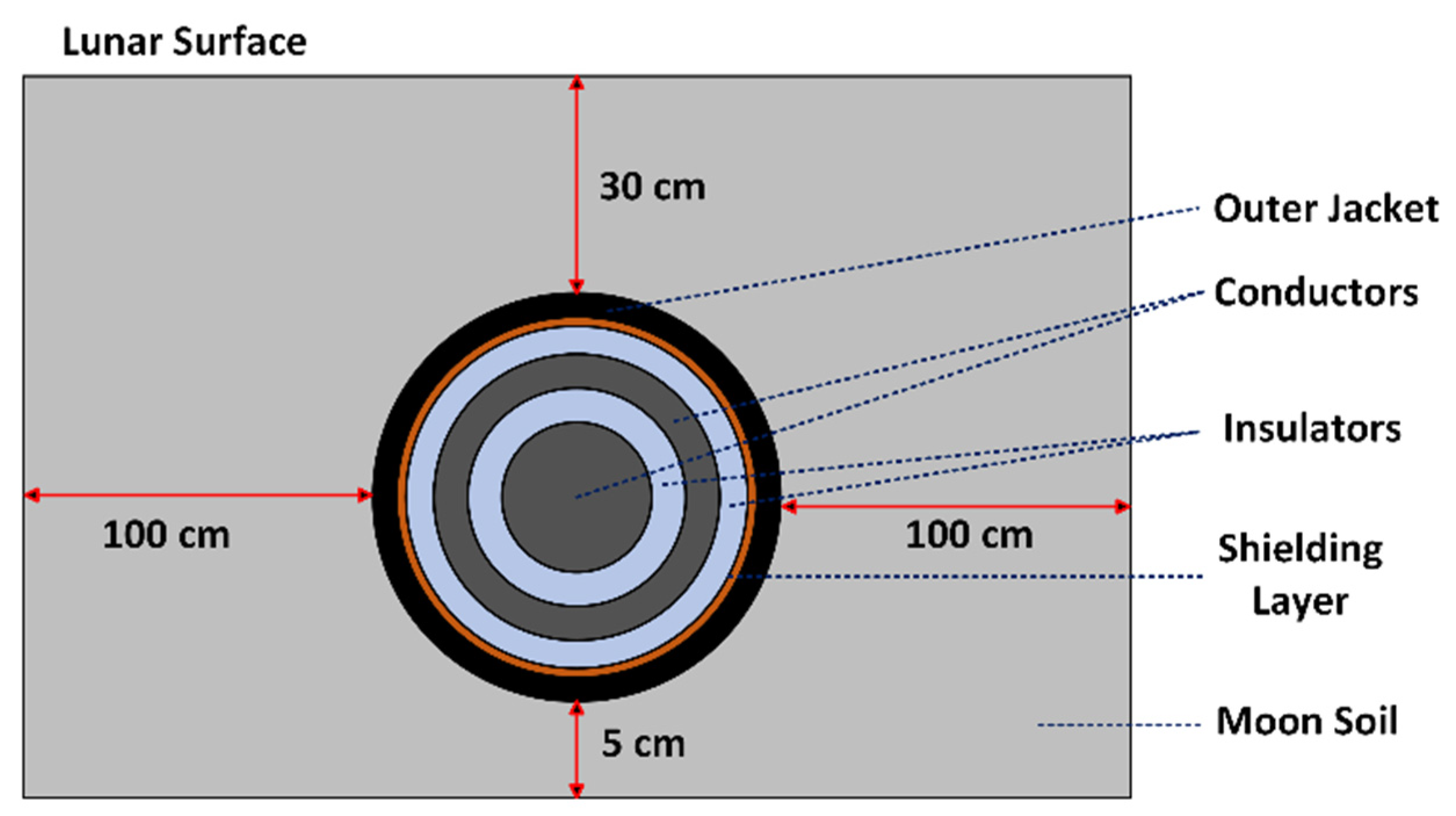
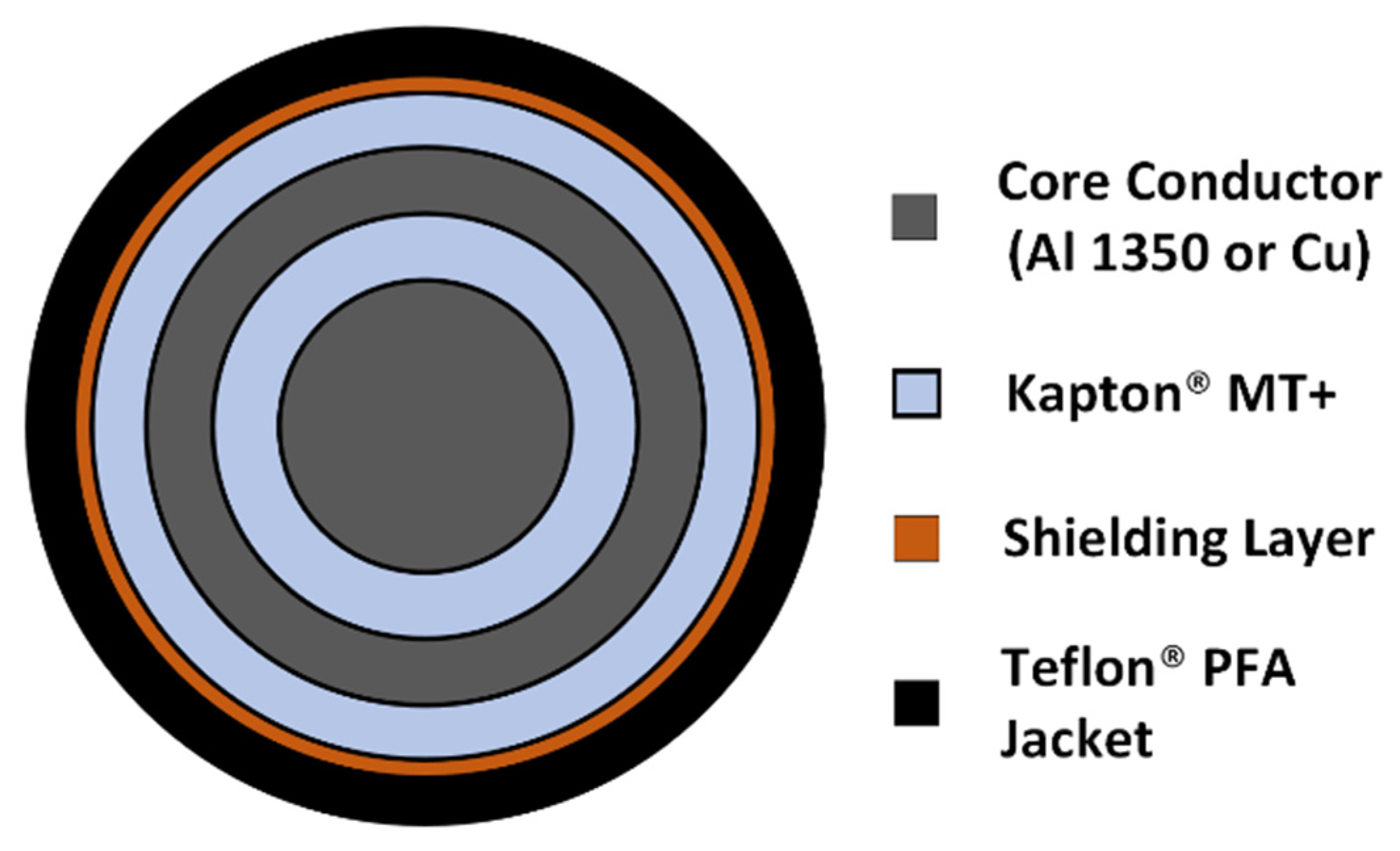
3.2. Proposed Insulation Designs

Designing cable insulation involves addressing challenges such as partial discharge (PD), arc tracking, arcing, and thermal management, particularly enhanced with increased voltages and currents. State-of-the-art terrestrial cables are typically constructed with insulation materials such as cross-linked polyethylene (XLPE) or ethylene propylene rubber (EPR), which provide excellent dielectric strength and thermal stability. The maximum working temperature of XLPE and NL-EPR cable is 105 °C. In some recent studies, the multilayer multifunctional electrical insulation (MMEI) system has emerged as an innovative and reliable insulation system for power cable design [26,27,28,29]. In another study, multiple layers of different insulating materials were used for coaxial cable design for lunar power transmission, but different day–night cycles were not considered [30]. When developing the insulation system for cables for lunar power transmission, the primary focus is selecting dielectric materials with high thermal conductivity and dielectric strength.
In the lunar environment, the MVDC coaxial power cable is vulnerable to several fault scenarios. Short circuits can occur due to insulation failure or external impacts, which may cause overheating and damage. Insulation breakdown is a significant risk given the extreme temperature variations and high radiation levels on the moon, potentially compromising the cable’s performance. Mechanical damage from impacts or vibrations associated with lunar activities also threatens the cable’s structural integrity. Additionally, the lunar surface experiences electromagnetic interference from natural sources, including solar radiation, cosmic rays, and interactions with the solar wind.
Figure 5 depicts the cable configuration of the bipolar coaxial cable proposed for this study. We selected Kapton® MT+ as the insulating material due to its high dielectric strength, exceptional thermal conductivity, and outstanding resistance to extreme temperatures and radiation on the moon. This guarantees reliable electrical performance and helps avoid insulation failure. While XLPE and NL-EPR have working temperature ranges of −40 to 105 °C and −35 to 105 °C, respectively, Kapton® MT+ offers an exceptional temperature range from −269 to 400 °C, making it highly suitable for extreme environments such as the lunar surface. Additionally, Kapton® MT+ has a higher thermal conductivity (0.75 W/m·K) compared to XLPE (0.46 W/m·K) and NL-EPR (0.3 W/m·K), which enhances its ability to manage heat dissipation effectively. Additionally, Kapton® MT+ has a significantly higher dielectric constant of 4.2 compared to the 2.5 of XLPE and NL-EPR, which can improve insulation properties and electrical performance under high-voltage conditions. High-temperature conductors, like 1350-O aluminum wires with 63% IACS conductivity and copper conductors, are utilized as the core conductors. For the heat generation analysis, we modeled the core conductors as solid single conductors. This approach assumes that the geometric and nominal cross-sections are equivalent for the purpose of simulating thermal effects and heat generation. The exterior of this design includes a Teflon® PFA jacket measuring 0.1016 mm in thickness, which was chosen for its excellent chemical resistance and thermal stability, provides additional protection against environmental stresses, and enhances overall durability. Additionally, a 0.127 mm-thick copper screen layer is placed between the outermost Kapton® MT+ layer and the Teflon® PFA jacket to shield against electromagnetic interference (EMI), which is critical for minimizing disruptions from external electromagnetic disturbances. Table 2 provides the material characteristics of the cables utilized in the bipolar MVDC power cable system.
The minimum (optimal) cable size is determined when reaching the thermal limit of its components. The maximum service temperature for 1350-O aluminum and copper is 260 °C, which is also the limit for the nickel-plated copper shielding layer [34]. The maximum continuous service temperature of Teflon® PFA and Kapton® MT+ are 260 °C [32] and 400 °C [35], respectively. The cables are designed to transmit three power levels, including 200 kW (low power), 1 MW (medium power), and 2 MW (high power), at the following two voltage levels: ±10 kV and ±5 kV. The voltage of the inner pole is positive, whereas the voltage of the outside pole is negative. Table 3 and Table 4 show the optimal geometrical characteristics obtained for bipolar cables for ±5 kV and ±10 kV voltages, respectively. To preserve the design criteria specified in Equations (11) and (12), the thickness of Kapton® MT+ layers is adjusted at different voltage levels.
To clarify, here, optimization refers to determining the number, type, and thickness of insulating materials that minimize weight and volume while meeting electrical and thermal requirements. The goal was to design a cable that handles the power and voltage efficiently under lunar environmental conditions, focusing on reducing weight and cross-sectional area without compromising performance or safety. Core conductor diameter and insulation thickness were determined using COMSOL simulations, ensuring that the cable reaches the maximum allowable temperature of 260 °C for the specified power level while operating at a fixed current.
The data provided in Table 3 and Table 4 illustrate the optimal geometrical properties for coaxial bipolar cables at different voltage levels and power ratings. It is evident from the tables that as the voltage level increases from ±5 kV to ±10 kV, the thickness of the inner insulator and the overall radius of the cable increase to accommodate the higher voltage stress. The inner insulator maintains a thickness of around 0.45 mm across various power levels and conductor materials for a ±5 kV voltage level. At a voltage level of ±10 kV, the thickness of the inner insulator grows to about 0.93 mm for power levels of 1000 kW and 2000 kW. However, for a power level of 200 kW, the thickness is 1.14 mm and 1.2 mm for aluminum and copper, respectively, indicating a greater than proportional increase in comparison to the voltage increase.

4. Simulation Results

Figure 6 presents a comparison of the weight per unit length across the three power levels. For 200 kW power transmission, the aluminum conductor at ±10 kV exhibits the lowest weight per unit length, measuring 0.0608 kg/m. This weight is approximately 12% less than that of the copper conductor at the same voltage level. When the voltage is reduced from ±10 kV to ±5 kV, using the same core conductor material (aluminum), the weight of the conductor increases to 0.0879 kg/m. This represents a significant increase of approximately 44.57% compared to the ±5 kV voltage level.
For a 1 MW power transmission, the aluminum conductor at ±10 kV voltage shows the lowest weight per unit length, measuring 0.3567 kg/m, which is roughly 39.41% lower than the copper conductor at the equivalent voltage level. Switching from a ±10 kV voltage to a ±5 kV voltage using the same core conductor material (aluminum) results in a weight increase to 0.9602 kg/m, about 169% higher than the weight compared to the ±10 kV voltage setup. If we compare copper with aluminum as a conductor at the ±5 kV voltage level, the weight increases to 1.8275 kg/m, which is approximately 90% higher than the aluminum conductor.
For a 2 MW power transmission, again, aluminum conductors exhibit the lowest weight per unit length at ±10 kV voltage, measuring 1.0092 kg/m. At the same voltage level, the weight of the copper conductor is approximately 1.8383 kg/m, which is about 82% greater than that of the aluminum conductor. Transitioning from a ±10 kV voltage to a ±5 kV voltage leads to a weight rise to 2.8991 kg/m for aluminum conductors, representing an 187% increase in weight compared to the ±10 kV voltage configuration. From the results, it can be concluded that the aluminum conductor consistently exhibits a lower weight per unit length compared to the copper conductor across various power levels and voltage configurations, making it the superior choice for minimizing mass.
Figure 7 presents a comparison of the cross-sectional area across the three power levels. For a 200 kW power transmission, the copper conductor operating at a voltage level of ±10 kV features the smallest cross-sectional area, measuring 22.602 mm2. This area is approximately 13.6% smaller than that of an aluminum conductor operating at the same voltage level. At a ±5 kV voltage level, the copper conductor still exhibits the lowest cross-sectional area of 22.934 mm2, although this is about 1.47% higher than at a ±10 kV voltage level. For power transmissions of 1 MW and 2 MW, similar outcomes were observed as those of the 200 kW transmission. Copper conductors require less area than aluminum conductors. At a voltage level of ±10 kV, the cross-sectional areas of the copper conductors are 97.631 mm2 for 1 MW and 259.22 mm2 for 2 MW. These dimensions are approximately 30.71% and 33.38% smaller, respectively, compared to the cross-sectional areas of the aluminum conductors operating at the same voltage level. These results indicate that copper conductors consistently demonstrate a smaller cross-sectional area compared to aluminum conductors across various power levels and voltage configurations. The reason is that aluminum conductors, due to their higher resistivity compared to copper, require a larger cross-sectional area to carry the same current.
In the context of designing cable systems for lunar power transmission, two key parameters are the weight per unit length and the cross-sectional area of the conductors. The analysis presented in Figure 6 and Figure 7 demonstrates that aluminum conductors exhibit the lowest weight per unit length, whereas copper conductors are characterized by the smallest cross-sectional area. To enable a more comprehensive comparison of different cable systems, we have introduced a parameter, J in Equation (10).
Figure 8 illustrates the comparison of parameter J across the three power levels. For a 200 kW power transmission, the smallest J value is 1.5617 g.mm observed in a copper conductor at ±10 kV, which is approximately 1.81% lower than that of an aluminum conductor, indicating a slight advantage in efficiency for the copper conductor at this power level. For a 1 MW power transmission, the aluminum conductor has the lowest J value of 50.266 g.mm at ±10 kV, which is approximately 12.5% lower than that of the copper conductor. At ±5 kV, the aluminum conductor also has the lowest J value compared to copper. For a 2 MW power transmission, the aluminum conductor again achieves the lowest J value of 392.69 g·mm at ±10 kV, which is about 17.6% lower than the copper conductor. At ±5 kV, the aluminum conductor similarly exhibits the lowest J value. Although aluminum conductors have a lower weight per unit length at ±10 kV, their higher resistivity necessitates a larger cross-sectional area, resulting in a higher J value compared to copper. Overall, aluminum conductors generally outperform copper conductors, except at the 200 kW power level. Additionally, higher voltage levels typically result in lower J values, reflecting reduced weight and cross-sectional area of the cables.
Figure 9 displays the simulated temperature progression of the cable surface over time. The analysis indicates a gradual rise in temperature from 0 h to 500 h, after which it stabilizes around 260 °C without abrupt fluctuations. Furthermore, the distribution of the electric field within the cable insulation was examined, as depicted in Figure 10. The maximum electric field strength observed is 2.24 × 10⁷ V/m, meeting the criteria outlined in Equation (11). Notably, the electric field across the dielectric remains nearly uniform throughout.
To evaluate our cable design against existing configurations, we simulated the Southwire 5 kV NL-EPR (SPEC 46101) cable [36] for 2 MW power transmission. The geometry of the bipolar Southwire cables under the lunar surface is shown in Figure 11. In this simulation, the positive and negative poles were assigned +5 kV and −5 kV, respectively. We adjusted the core conductor radius of the NL-EPR cable to ensure it stayed within the maximum temperature limit of 105 °C. Other aspects of the simulation matched the specifications of the Southwire cable. The properties of the material used for the simulation are shown in Table 2. The comparison between our designed cable and the Southwire cable is detailed in Table 5.
From the above results, it can be seen that the designed coaxial cable has less weight per unit length and cross-sectional area than the Southwire 5 kV cable. For a 2 MW power transmission at a ±5 kV voltage level, the coaxial configuration weight per unit length is 5.7802 kg/m, which is about 25% lower than the NL-EPR cable. Also, the designed cable required a lower cross-sectional area than the NL-EPR cable, whereas for the designed cable, the area is 693.81 mm2, which is about 60% lower than the NL-EPR cable.
The expected lifespan of the MVDC coaxial power cable designed for lunar conditions is influenced by several critical factors, including material degradation, thermal cycling, and radiation exposure. Although we simulated the cable with a runtime of 2000 h, a direct assessment of its lifespan was not conducted. The cable’s longevity will be shaped by factors similar to those affecting typical underground cables, which generally last between 20 and 40 years. Unlike standard underground cables, which benefit from protection against environmental stresses and maintenance practices, the lunar cable faces unique challenges, including extreme temperature variations, high radiation levels, and potential mechanical impacts. Our design employs Kapton® MT+ insulation and a Teflon® PFA jacket, which were chosen for their exceptional durability against extreme temperatures and radiation. The use of these materials helps manage the significant temperature fluctuations on the lunar surface and provides resistance to radiation, both of which are crucial for maintaining performance in the harsh lunar environment. However, without experimental testing, the precise lifespan remains uncertain. Ongoing monitoring and further assessments will be essential to verify the cable’s operational integrity and reliability under lunar conditions.

5. Conclusions

In this study, we focus on the design and analysis of MVDC bipolar coaxial cables for lunar power transmission. While prior research has explored cable designs for terrestrial applications, it often neglects the unique challenges of the lunar environment, such as its near-perfect vacuum and extreme conditions. Our work addresses this by developing a comprehensive coupled electrothermal model tailored for power transmission approximately 30 cm below the lunar surface. Key parameters for effective cable design in this context include the selection of materials with high thermal conductivity and dielectric strength. We have chosen Kapton® MT+ for insulation due to its superior properties in these areas and evaluated the performance of aluminum and copper conductors as potential core conductor materials. Our findings indicate that aluminum conductors generally perform better than copper conductors at medium and high power levels (1 MW and 2 MW). Additionally, higher voltage levels (±10 kV) have been identified as advantageous for achieving optimal cable design and enhancing power transfer efficiency. Effective thermal management is critical in the lunar vacuum environment, making it essential to consider thermal conductivity and insulation performance at low temperatures. The cables developed in this study provide a viable solution for efficient power transmission in the lunar environment, addressing the challenges and requirements for future lunar power infrastructure. Also, this study provides valuable insights into applying advanced materials and design methodologies in extreme environments, which could benefit future research and development in this area. To the best of our knowledge, such a study has not been reported to date, and we are, for the first time, presenting such a study in these voltage and power rates for power transmission on the moon. (i) The complex coupled electrical and thermal modeling, (ii) optimal design of MVDC power cables via (a) an innovative MMEI approach and (b) considering high-performance materials in both terms of heat transfer capability and dielectric performance, (iii) accurately taking in account lunar environments and determining the best location for cables regarding those harsh conditions, and (iv) carrying simulations for three different power levels (low, medium, and high) at two voltage levels (±5 kV and ±10 kV) and for two different materials (Cu or Al) for the core conductor (in total studying 3 × 2 × 2 = 12 case studies) provides a comprehensive study in this field. This paper is highly valuable and an important step forward in one of the most important areas of aerospace, the powering of the moon.

Author Contributions

Conceptualization, A.S. and M.G.; methodology, A.S. and M.G.; validation, A.S. and M.G.; formal analysis, A.S. and M.G.; investigation, A.S. and M.G.; writing—original draft preparation, A.S.; writing—review and editing, M.G.; supervision, M.G.; project administration, M.G.; funding acquisition, M.G. All authors have read and agreed to the published version of the manuscript.

Funding

This research received no external funding.

Data Availability Statement

Data are contained within the article.

Conflicts of Interest

The authors declare no conflicts of interest.

References

  1. Khan, Z.; Vranis, A.; Zavoico, A.; Freid, S.; Manners, B. Power system concepts for the lunar outpost: A review of the power generation, energy storage, power management and distribution (PMAD) system requirements and potential technologies for development of the lunar outpost. AIP Conf. Proc. 2006, 813, 1083–1092. [Google Scholar]
  2. Gordon, L.B.  Electrical Transmission on the Lunar Surface Part I—DC Transmission. 2001. Available online: https://ntrs.nasa.gov/api/citations/20040191588/downloads/20040191588.pdf (accessed on 13 April 2024).
  3. Gordon, L.B.; Gaustad, K.L. Vacuum insulation for a lunar-based power system. IEEE Trans. Dielectr. Electr. Insul. 1995, 2, 299–311. [Google Scholar] [CrossRef]
  4. Boretz, J.; Koslover, M. Synthesis of an electrical power system for a manned lunar base. IEEE Trans. Aerosp. Electron. Syst. 1969; AES-5, 770–788. [Google Scholar]
  5. IEC 60287-1-1:2006; Electric Cables-Calculation of the Current Rating-Part 1-1: Current Rating Equations (100% Load Factor) and Calculation of Losses-General. IEC: Geneva, Switzerland, 2006; pp. 1–136.
  6. IEC 60853-1:1985; Calculation of the Cyclic and Emergency Current Rating of Cables. Part 1: Cyclic Rating Factor for Cables up to and Including 18/30(36) kV. IEC: Geneva, Switzerland, 1985; pp. 1–39.
  7. IEC 60986:2000; Short-Circuit Temperature Limits of Electric Cables with Rated Voltages from 6 kV (Um = 7.2 kV) up to 30 kV (Um = 36 kV). IEC: Geneva, Switzerland, 2000; pp. 1–19.
  8. IEC TR 62095:2003; Electric Cables-Calculations for Current Ratings-Finite Element Method. IEC: Geneva, Switzerland, 2003; pp. 1–69.
  9. Smith, R.E.; West, G.S. Space and Planetary Environment Criteria Guidelines for Use in Space Vehicle Development. Volume 1: 1982 Revision; 1983; Volume 83, p. 18816. Available online: https://ntrs.nasa.gov/api/citations/19830019790/downloads/19830019790.pdf (accessed on 13 April 2024).
  10. Podnieks, E.R. Environmental Considerations for Lunar Base Engineering. In Engineering, Construction, and Operations in Space; ASCE: Reston, VA, USA, 1988; pp. 55–66. [Google Scholar]
  11. Johnson, F.S.; Carroll, J.M.; Evans, D.E. Vacuum Measurements on the Lunar Surface. J. Vac. Sci. Technol. 1972, 9, 450–456. [Google Scholar] [CrossRef]
  12. Hoffman, J.H.; Hodges, R.R.; Evans, D.E. Lunar Orbital Mass Spectrometer Experiment. Lunar Planet. Sci. Conf. Proc. 1972, 3, 2205. [Google Scholar]
  13. Hodges, R.R.; Hoffman, J.H.; Evans, D.E.  Apollo 16—Lunar Orbital Mass Spectrometer Experiment. 1972. Available online: https://www.lpi.usra.edu/lunar/documents/NASA%20SP%20315.pdf (accessed on 13 April 2024).
  14. Strangway, D.W. Moon: Electrical Properties of the Uppermost Layers. Science 1969, 165, 1012–1013. [Google Scholar] [CrossRef] [PubMed]
  15. Keihm, S.J.; Langseth, M.G. Surface Brightness Temperatures at the Apollo 17 Heat Flow Site—Thermal Conductivity of the Upper 15 Cm of Regolith. Lunar Planet. Sci. Conf. Proc. 1973, 4, 2503. [Google Scholar]
  16. Langseth, M.G.; Clark, S.P.; Chute, J.L.; Keihm, S.J.; Wechsler, A.E. Heat Flow Experiment. Sci. Rep. 1972, 289, 11. [Google Scholar]
  17. General Cable Catalogs, Electric Utility (U.S.) Products. Available online: https://prysmian-group.dcatalog.com/v/Electric-Utility-(US)/ (accessed on 13 April 2024).
  18. Cour-Palais, B.G.; Flaherty, R.E.; Brown, M.L. Apollo Window Meteoroid Experiment. Available online: https://ntrs.nasa.gov/citations/19720015188 (accessed on 13 April 2024).
  19. Cour-Palais, B.G.; Brown, M.L.; Mckay, D.S. Apollo Window Meteoroid Experiment. Available online: https://ntrs.nasa.gov/citations/19730013033 (accessed on 13 April 2024).
  20. Brownlee, D.; Bucher, W.; Hodge, P. Micrometeorite impact analyses. In Analysis of Surveyor 3 Material and Photographs Returned by Apollo 12; NASA: Washington, DC, USA, 1972. [Google Scholar]
  21. Kirkici, H.; Rose, M.F.; Chaloupka, T. Experimental study on simulated lunar soil, high voltage breakdown and electrical insulation characteristics. IEEE Trans. Dielectr. Electr. Insul. 1996, 3, 119–125. [Google Scholar] [CrossRef]
  22. Kirkici, H.; Rose, M.F. High voltage transmission line operation in simulated lunar environment. In Proceedings of the Ninth IEEE International Pulsed Power Conference, Albuquerque, NM, USA, 21–23 June 1993. [Google Scholar]
  23. Heiken, G.; Vaniman, D.; French, B.M. Lunar Sourcebook; Cambridge University Press: New York, NY USA, 1991. [Google Scholar]
  24. Jordan, A.P.; Stubbs, T.J.; Zeitlin, C.; Spence, H.E.; Schwadron, N.A.; Zimmerman, M.I.; Farrell, W.M. On the Interaction Between Highly Energetic Charged Particles and the Lunar Regolith. In Proceedings of the Lunar and Planetary Science Conference, Woodlands, TX, USA, 19–23 March 2012; p. 2619. [Google Scholar]
  25. Baferani, M.A.; Li, C.; Shahsavarian, T.; Ronzello, J.; Cao, Y. High temperature insulation materials for dc cable insulation—Part I: Space charge and conduction. IEEE Trans. Dielectr. Electr. Insul. 2021, 28, 223–230. [Google Scholar] [CrossRef]
  26. Shin, E.E.; Scheiman, D.A.; Lizcano, M. Lightweight, durable, and multifunctional electrical insulation material systems for high voltage applications. In Proceedings of the 2018 AIAA/IEEE Electric Aircraft Technologies Symposium (EATS), Cincinnati, OH, USA, 12–14 July 2018; pp. 1–21. [Google Scholar]
  27. Saha, A.; Azizi, A.; Ghassemi, M. Optimal Bipolar MVDC Power Cable Designs for Future Wide-Body All Electric Aircraft. IEEE Trans. Dielectr. Electr. Insul. 2024, 31, 2074–2083. [Google Scholar] [CrossRef]
  28. Saha, A.; Ghassemi, M. Challenges in Electrical Insulation Materials and Thermal Management for Medium Voltage Power Cables for Envisaged Wide-Body All-Electric Aircraft. In Aeronautics-Characteristics and Emerging Technologies; Li, L., Ed.; IntechOpen: London, UK, 2024; Available online: https://www.intechopen.com/online-first/1194193 (accessed on 18 August 2024).
  29. Saha, A.; Azizi, A.; Ghassemi, M. Optimized Design of ±5 kV, 1 kA Rectangular Power Cable for a Low Pressure of 18.8 kPa for Envisioned All-Electric Wide-Body Aircraft. IEEE Access 2024, 12, 28654–28665. [Google Scholar] [CrossRef]
  30. Saha, A.; Ghassemi, M. High power density, cost-effective HVDC cables for power transmission on the moon. In Proceedings of the IEEE Texas Power and Energy Conference (TPEC), College Station, TX, USA, 12–13 February 2024; pp. 1–5. [Google Scholar]
  31. DuPont™ Kapton® MT+. Available online: https://materials-direct.com/wp-content/uploads/2021/05/K-MT-Eng-2019.pdf (accessed on 3 May 2024).
  32. DuPont™ Teflon® PFA. Available online: https://catalog.cshyde.com/Asset/Data%20Sheet%2023-__PFA%20DuPont%20PFA%20Film%20Data%20Sheet.pdf (accessed on 3 May 2024).
  33. Saha, A.; Ghassemi, M. MVDC Bipolar Power Cables with Rectangular Geometry Design for Envisaged All-Electric Wide-Body Aircraft. In Proceedings of the IEEE Texas Power and Energy Conference (TPEC), College Station, TX, USA, 12–13 February 2024; pp. 1–5. [Google Scholar]
  34. Available online: https://www.sanghviaerospace.com/pdf/polyimide-cable-partnumbering381-27500.pdf (accessed on 13 April 2024).
  35. Available online: https://americandurafilm.com/film-distribution/kapton-film/ (accessed on 13 April 2024).
  36. 1/0-19 CU 90 MILS NL-EPR 5KV 100% T/S BLACK SIMpull PVC JACKET UL|Southwire. Available online: https://www.southwire.com/wire-cable/medium-voltage-power-cable/spec46101-cu-compressed-5kv-nlepr-insulation-100-il-pvc-jacket-mv-105-tray-rated-sunlight-resistant-for-direct-burial/p/55565699 (accessed on 3 August 2024).
Figure 1. (a) Surface temperature of lunar soil over a lunar cycle; (b) mean temperature vs. depth produced by the Apollo 15 and 17 thermal property models [15].
Aerospace 11 00685 g001
Figure 2. Geometry of the coaxial bipolar cables beneath the lunar surface.
Aerospace 11 00685 g002
Figure 3. Lunar surface temperature variation throughout the simulation period.
Aerospace 11 00685 g003
Figure 4. Close-up view of the mesh around the cable.
Aerospace 11 00685 g004
Figure 5. Cable configuration of the coaxial bipolar cable system.
Aerospace 11 00685 g005
Figure 6. Weight per unit length of the cables at three power levels.
Aerospace 11 00685 g006
Figure 7. Cross-sectional area of the cables at three power levels.
Aerospace 11 00685 g007
Figure 8. Parameter J of the cables at three power levels.
Aerospace 11 00685 g008
Figure 9. Simulated temperature curve of the cable surface over time for 2 MW power transmission at ±10 kV voltage.
Aerospace 11 00685 g009
Figure 10. Electric field distribution of the coaxial bipolar cable system for 2 MW power transmission at ±10 kV voltage.
Aerospace 11 00685 g010
Figure 11. The geometry of the two cables under 30 cm beneath the lunar surface.
Aerospace 11 00685 g011
Table 1. Parameters of electrical conductivity [25].
Parameter a (K) b (mm/kV) σ 0 (S/m)
ETFE40610.030972.027 × 10−10
PI33190.055581.677 × 10−9
Table 2. Material properties used in bipolar cables [2,28,31,32,33].
MaterialDensity (kg·m−3)Thermal Conductivity (W·m−1·K−1)Dielectric ConstantDielectric Strength (V·m−1)
Aluminum2705237--
Copper8960400--
Kapton® MT+ (500 MT+)14200.754.2114.173 × 106
Teflon® PFA21500.1952256 × 106
XLPE9300.462.5-
NL-EPR8600.32.5-
Semiconducting layer105510--
PVC13500.19--
Moon’s Soil-0.010--
Table 3. Optimal geometrical properties of the coaxial bipolar cables for ±5 kV voltage level.
Power Level (kW)Core Conductor MaterialRadius of the Core Conductor (mm)Thickness
of the Inner
Insulator (mm)
Thickness
of the Outer
Conductor (mm)
Thickness
of the Outer
Insulator (mm)
Overall
Radius of the Cable (mm)
200Al1.680.480.57640.2256.38
Cu1.320.500.42830.2255.40
1000Al6.950.462.74950.22510.61
Cu5.520.462.1580.2258.59
2000Al12.50.455.04850.22518.45
Cu9.960.453.99750.22514.86
Table 4. Optimal geometrical properties of the coaxial bipolar cables for ±10 kV voltage level.
Power Level (kW)Core Conductor MaterialRadius of the Core Conductor (mm)Thickness
of the Inner
Insulator (mm)
Thickness
of the Outer
Conductor (mm)
Thickness
of the Outer
Insulator (mm)
Overall
Radius of the Cable (mm)
200Al0.861.140.17710.482.89
Cu0.661.20.11370.482.68
1000Al3.760.941.3190.456.70
Cu2.960.940.99610.455.57
2000Al6.910.932.61050.4511.13
Cu5.460.932.0150.459.08
Table 5. Comparison between existing cable and designed cable.
Cable TypeCore Conductor MaterialRadius of the Core Conductor (mm)Overall Radius of the Cable (mm)Weight per Unit Length for 2 Poles (kg/m)Total Cross-Sectional Area (mm2)
NL-EPR 5 kV CableCu10.6516.68257.71571748.6
Designed Coaxial CableCu9.9614.8615.7802693.81
Disclaimer/Publisher’s Note: The statements, opinions and data contained in all publications are solely those of the individual author(s) and contributor(s) and not of MDPI and/or the editor(s). MDPI and/or the editor(s) disclaim responsibility for any injury to people or property resulting from any ideas, methods, instructions or products referred to in the content.

