Abstract
The missions of modern aircraft require multiple abilities, such as highly efficient taking-off and landing, fast arrival, and long-endurance hovering. It is difficult to achieve all technical objectives using traditional aircraft design technology. The active flow control technology using the concept of a co-flow jet (CFJ) is a flow control method without a mass source that does not require air from the engine. It has strong flow control ability in low-speed flow, can greatly improve the stall angle of the aircraft, and can obtain large lift enhancement. At transonic conditions, it can lead to a larger lift–drag ratio with a small expense. CFJ technology has great application potential for aircraft due to its flexible control strategy and remarkable control effect. In this paper, the concept of a combination of CFJ and variable camber technology is proposed which realizes the change of airfoil camber to meet different task requirements with the movable droop head. By using the built-in ducted fan, air is blown and sucked in the jet channel so as to realize CFJ flow control. In a state of high-speed flight, complete geometric restoration is achieved by closing the channel and retracting the droop head. In this paper, the design and aerodynamic analysis of a CFJ device with variable camber based on a supercritical airfoil with small camber and a small leading-edge radius are carried out using the computational fluid dynamics (CFD) method. Comparative studies are conducted for different schemes on the taking off and landing performances, and discussions are had on core technical parameters such as power consumption. The results indicate that by utilizing the CFJ technology with more than 10 degrees of droop device, the maximum lift coefficient of a supercritical airfoil with a small camber and leading-edge radius, which is suitable for transonic flight, can be increased to a value larger than 4.0.
1. Introduction
According to the characteristics of the flow control method, the flow control technique can be divided into passive flow control and active flow control (AFC). Passive flow control (PFC) achieves the control of the flow field by optimizing the aerodynamic shapes of the wing or components such as slats, flaps, or hinge-like devices at the trailing edge, which change the length and camber of the airfoil during take-off, landing, and cruise condition accordingly; the wing fences which obstruct spanwise airflow; vortex generators (VG) which could trigger vortical flow then transport downstream to suppress flow separation; and the winglet installed at wingtip to reduce the strength of wingtip vortices in aeronautical engineering. In hydraulic machinery, PFC also plays a very important role, such as the cavitating-bubble generator designed and experimentally investigated by Kavivar et al. [1], in which the spanwise wedge-type is placed at the leading edge of the hydrofoil, and the generated unsteady partial cavitation and cloud cavitation could help to suppress the laminar separation bubble so that the overall performance, including lift enhancement, drag-reduction, and suppressing cavitation-induced vibrations and erosion, is achieved. A detailed review of VG-type PFC can be found in [2]. The main drawback of all types of PFCs is that they usually operate well in design conditions but are poor in off-design conditions, while AFC achieves the purpose of improving the flow field by applying an appropriate disturbance to the incoming flow field and coupling it with the intrinsic mode of the flow. Its advantage lies in being able to appear at the required time and location flexibly and achieving control of the global flow field through local disturbance [3]. Its typical applications in the aviation industry include the active with mass source, such as externally blown flap (EBF) [4], which makes use of the exhausted gas of the main engine to gain significant lift enhancement. Some newly proposed AFC via blowing, such as internally blown flaps (IBF) [5], microjets [6], sweeping jets [7], and so on, could gain certain aerodynamic benefits with a smaller jet momentum coefficient than EBF. The IBF used in [5] also makes use of the so-called Coanda effect to increase the circulation of the airfoil significantly. A review of AFC with the Coanda effect on a flapless subscale demonstrator aircraft can be found in [8]. Additionally, some innovative AFC technologies that have no mass source, such as plasma jets [9,10,11], synthetic jets [12], and co-flow jets (CFJ) [13,14,15], were also proposed and investigated numerically and/or experimentally. The aerodynamic benefits, including lift enhancement, drag reduction, and maneuverability or stealth, are achieved at different levels. Suction can also be used as AFC, as seen in the recent work done by Sun et al. [16]. The latest review of AFC can be found in Greenblatt and William [17]. Because of the flexibility and efficiency of active flow control technology, it has become one of the key technologies in the modern aviation industry.
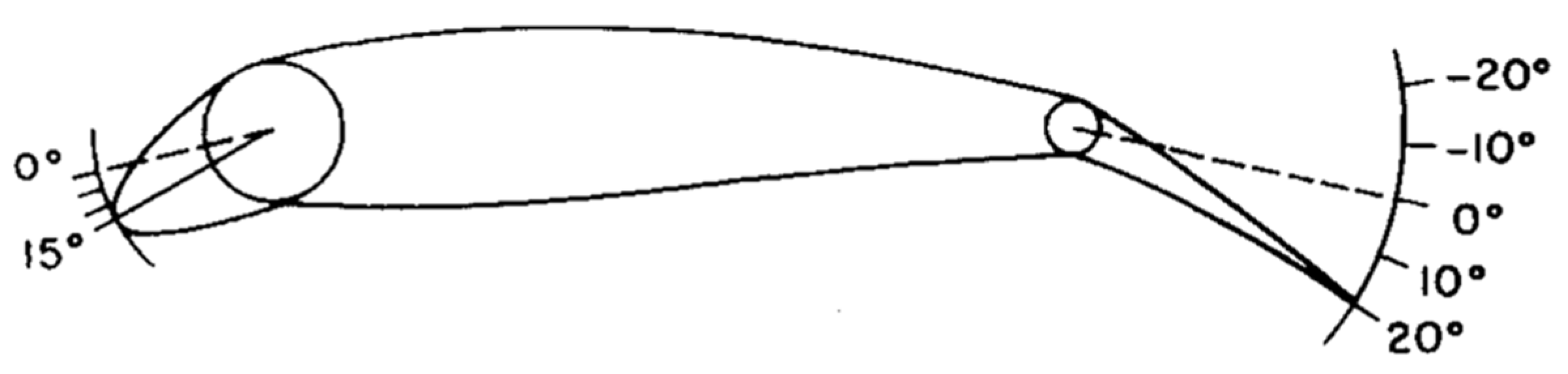
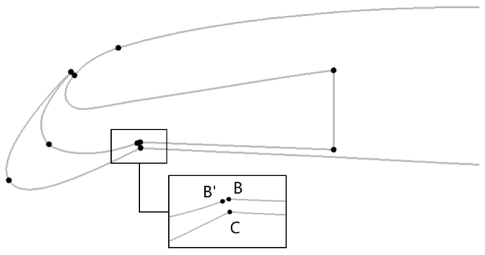
Lift augmentation is a very important issue for current unmanned aerial vehicles (UAV). The most successful and widely used in transport aircraft is the high-lift system, which requires a very complex support and driving mechanism. Thus, it is difficult to apply on UAVs with extremely high requirements for high-speed cruising, payload, and stealth. A much simpler technology with a similar level of lift enhancement is the leading-edge droop concept. Its principle is to droop the entire head of the airfoil through a bending device to obtain an airfoil with a larger camber and effective leading-edge radius compared with the baseline airfoil. Preey et al. [18] carried out the droop treatment of the leading edge for an FX63-137 airfoil under low Reynolds number conditions, and the head and main wing were connected by the hinge way, as shown in Figure 1. The results show that the leading-edge droop makes the upper wing surface have a more favorable pressure distribution, thus delaying the stall angle and increasing the maximum lift coefficient effectively. In addition to the scheme of the leading-edge droop by the rigid deflection, a series of further studies on the leading-edge droop using the morphing skin has been successively proposed [19,20,21]. Lu et al. [22] used the passive control combination of the leading-edge droop and trailing-edge camber for the GAW-1 airfoil, where the trailing-edge camber included trailing-edge flap and trailing-edge aileron. The maximum thickness of this airfoil was 17% c, with a large leading-edge radius, a flat upper surface, and a large camber at the trailing edge. The incoming flow had a low speed. The results showed that the leading-edge droop caused the formation of two peak regions of negative pressure in the leading edge, reducing the adverse pressure gradient effectively and suppressing the flow separation. He et al. [23] took the airfoil at the kink station of a subsonic UAV as the baseline airfoil, with a maximum thickness of 12% c, a flap chord length of 0.25 c, and a baseline flap deflection angle of 65°. A leading-edge droop design using the method of rigid deflection was combined with IBF. The results showed that the leading-edge droop also improved the pressure distribution, forming the second peak region of negative pressure at the location of the arc connection.
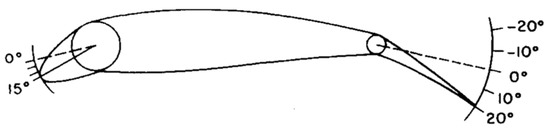
Figure 1.
Schematic of drooped airfoil from reference [2].
The CFJ scheme was first proposed by Zha et al. [13] in 2004, and his paper in 2007 [14] further derived the calculation of the lift and drag coefficients for the CFJ airfoil. The basic idea of this technology is to open the suction slot near the trailing edge of the wing and the blowing slot near the leading edge. A ducted fan is arranged inside the wing to achieve the blowing and suction cycle of airflow. Under the cooperation of injection and suction, the circulation on the surface of the airfoil is increased without the input of energy from the main engine, having the characteristics of a zero-mass jet. The effects of the CFJ technique vary with incoming flow conditions. Zha et al. [14,15,24] and Lefebvre et al. [25] discussed the effects of increasing lift and reducing drag as well as energy consumption of the CFJ technique under subsonic and transonic conditions, respectively. The results under low subsonic conditions show that before the jet forms a shock wave, as the Mach number increases, the maximum lift coefficient and the stall angle increase correspondingly, and the jet power consumption shows a decreasing trend. When the Mach number increases to 0.4, due to the appearance of a shock wave, the jet injection is hindered, and the boundary layer separation is advanced, resulting in a decrease in the stall angle and an increase in the jet power consumption. Liu et al. [26] found in the numerical simulation of the transonic supercritical CFJ airfoil that when the aircraft is in the cruise state with a small angle of attack, the shock wave position is upstream of the airfoil and has little effect on the suction slot. CFJ can provide higher aerodynamic efficiency compared with the baseline airfoil; as the angle of attack increases, the shock wave moves backward to the location of the suction slot, resulting in a large total pressure loss at the suction slot and a decrease in aerodynamic efficiency compared with the baseline airfoil. In subsequent works, Zha et al. [27,28,29,30] further discussed the influencing factors of CFJ technology. References [27,28] explored the advantages of CFJ airfoil in increasing the stall margin as well as maximum lift and reducing drag and studied the influences of the geometric parameters of the jet device and the jet momentum coefficient. Lefebvre et al. [29,30] discussed the shape of the suction surface and increased the jet momentum coefficient by changing the mass flow rate and the height of the jet to explore further the influences of the jet momentum coefficient. Dano et al. [31,32] proposed the concept of discrete co-flow jets in order to better improve the efficiency of the CFJ device and reduce energy loss. The results show that the discrete jet has a better control effect on the flow field under the same power consumption compared with the continuous jet. Liu et al. [33] carried out the exploration of CFJ airfoils early. Taking the DFVLR R-4 airfoil as the baseline airfoil, the improvement effect achieved by using CFJ on the aerodynamic performance of the airfoil was introduced, and the lift augmentation mechanism was explained from the two aspects of increasing the circulation of the airfoil and injecting energy into the boundary layer. Xu et al. [34] took NACA6415 as the baseline airfoil and discussed the influences of key parameters, such as the jet momentum coefficient and the sizes and positions of blowing and suction slots, on the aerodynamic performance of the airfoil under low Reynolds numbers. Zhang et al. [35] explored in detail the influence laws of the basic parameters, such as the size of the blowing slot, the size of the suction slot, and the sink amount of the upper wing surface on lift increment and drag reduction by wind tunnel experiment, taking the OA312 airfoil as the baseline airfoil and obtaining the optimal parameter values at low-speed conditions. Shi et al. [36] applied CFJ technology to the baseline airfoil of a vertical tail. The results show that compared with the baseline airfoil, the flow separation for the CFJ airfoil is greatly suppressed. Wang et al. [37] investigated the key parameters affecting the performance of CFJ airfoils, and they found that the momentum coefficient of the jet is the most important one. A trial of CFJ technology to the high-speed fly wing can be found in the work of Wang et al. [38].
In order to obtain good cruise characteristics at high subsonic and transonic speeds, the aircraft usually adopt airfoils with a small camber and small leading-edge radius, leading to poor low-speed aerodynamic characteristics, poor stall characteristics, and small stall angles. Thus, when aircraft of this type have the requirement of short take-offs and landings (STOL), such as shipboard aircraft, it is necessary to apply flow control technology, which can increase the stall angle and lead to larger lift efficiency. Nevertheless, due to the small thickness and the limited space, it is difficult to arrange the flow control scheme in aircraft of this type, and relevant studies are rare. Further, the application of a flow control scheme, either active or passive, has some defects. For example, the droop head scheme using rigid deflection or morphing skin needs a complex set of mechanical devices. The CFJ technique arranges blowing and suction slots on the wing surface, destroying the stealth performance. In this paper, an improved scheme for this kind of airfoil is proposed, which combines the rigid droop head with CFJ to overcome the defects of both passive control and active control as much as possible. Note that the deflection of the rudder at the trailing edge is abandoned herein, as it leads to a shift of the stall to a smaller angle, although it can induce significant lift enhancement. The control effect of this scheme is examined under low Mach-number conditions. Its design principle is to arrange the blowing pipe, the suction pipe, and the ducted fan inside the wing. The leading-edge part of the wing is a movable component that rotates rigidly around a fixed axis through a hinge mechanism. After the aircraft takes off, the leading-edge part is drooped according to a fixed angle after passing through an arc-shaped track, and a blowing channel is formed at the drooping corner. When the aircraft begins to cruise, the drooped part is retracted, and the blowing slot is also closed. The aircraft cruises at high speed with a clean configuration, maintaining the original stealth characteristics. The length of the movable part of the head is less than 10% c, with the purpose of controlling structural weight.
2. Physical Model and Computational Method
2.1. Model and Mesh
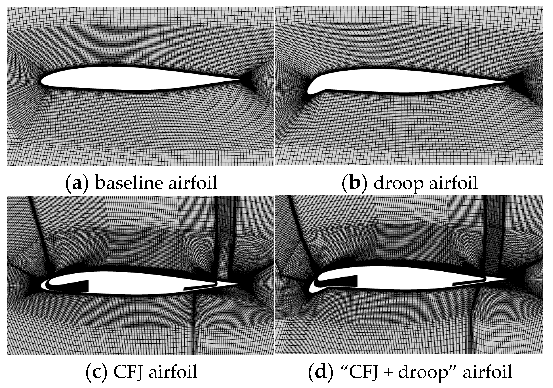
Figure 2 presents the meshes of the four airfoils used, including the baseline airfoil (a), droop airfoil (b), CFJ airfoil (c), and the “CFJ + droop” airfoil (d). The flow field is discretized into block-structured meshes, with refined meshes applied to critical locations such as the injection slot, suction slot, and wake region. The mesh growth rate at the first layer for non-CFJ and CFJ airfoils is set to 1.2. The mesh height at the first layer for the non-CFJ airfoil is approximately 2.5 × 10⁻⁶ c, while that for the CFJ airfoil is approximately 7 × 10⁻⁶ c (c is chord length). The flow field parameters in this paper are Ma = 0.2, the pressure of incoming flow is the standard atmospheric pressure, and the temperature is 288.15 K. The chord length c of the baseline configuration is a supercritical airfoil with a small leading-edge radius and camber. The selected case has a chord length of 2.8 m, with a maximum thickness of approximately 12% c, which is a typical thin airfoil designed to achieve good performance in high-subsonic and transonic conditions.
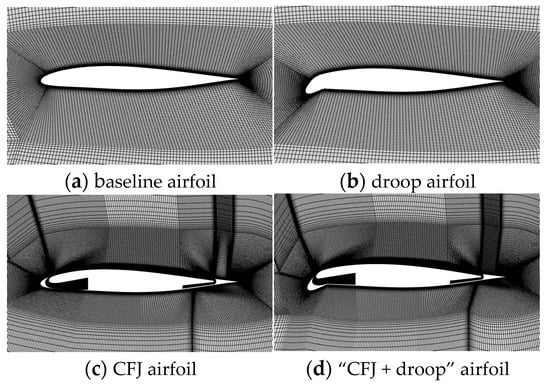
Figure 2.
The meshes for different airfoils: (a) baseline airfoil, (b) droop airfoil, (c) CFJ airfoil, and (d) “CFJ + droop” airfoil.
In this paper, the numerical simulation software used is Fluent 18.2, in which the pressure-based solver is used to solve the steady RANS equations. The S-A turbulence model is selected [39]. The jet inlet is set to a pressure inlet, and the jet outlet is a flow inlet.
2.2. Parameters and Design of CFJ
2.2.1. Power Consumption Coefficient
The cost of AFC devices is a key issue for aeronautical applications. The power consumption of the internal pressurization system of a CFJ airfoil can be calculated according to the following air parameters before and after pressurization:
where cp is the specific heat of air at constant pressure, T1 is the total temperature of jet air before pressurization, η is the efficiency of the pressurization system, and P1 and P2 are the total pressures of jet air on the mesh before and after pressurization, respectively. γ is the specific heat ratio and is equal to 1.4 in the standard state. In CFD, P1 and P2 are the mass-averaged total pressure on the boundary.
The dimensionless form of power is calculated using Equation (2) and is used as the equivalent drag coefficient due to energy consumption by the compressor:
2.2.2. Lift and Drag Coefficients
When calculating the aerodynamic force of the CFJ airfoil, in addition to the aerodynamic forces obtained by integrating and summating the pressure and friction forces on the surface, the inverse forces due to the actions of the jet momentum and the pressures on the slot of the jet and suction should also be considered.
The lift coefficient of the CFJ airfoil is as follows:
The drag coefficient is as follows:
where RL and RD represent the lift force and drag force on the surface of the CFJ airfoil, and FL,CFJ and FD,CFJ are the inverse forces due to the actions of the jet momentum and the pressures on the slot of jet and suction, which is calculated by integrating the corresponding force on each mesh point in the slot of jet and suction, and it is different to the approach as given in reference [14].
In order to evaluate the efficiency of the CFJ airfoil, the modified drag coefficient is used, which is the sum of the drag coefficient of the CFJ airfoil and the dimensionless form of power. When CD,eff is close to the drag coefficient of a clean airfoil without additional energy cost, it corresponds to a high efficiency of the CFJ method.
2.2.3. Design Method
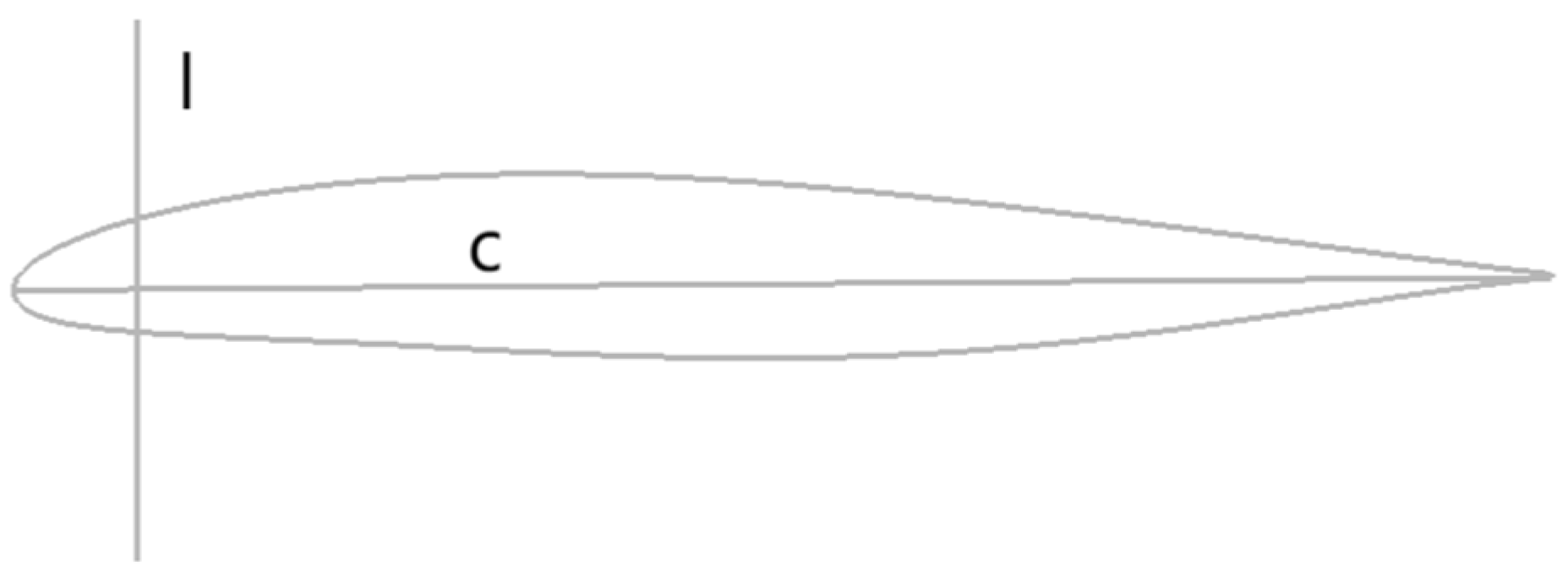
In this section, taking the “CFJ + droop” airfoil with the rotation point at the 8% c location and a droop angle of 30° as an example, the design method is presented. Figure 3 shows the baseline state of the airfoil studied, where the chord C and the vertical line I at 8% c location are pointed. Figure 4 shows the suction channel which is kept unchanged and not the part of the design process.
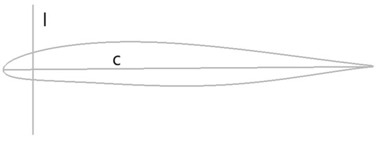
Figure 3.
The baseline airfoil and auxiliary line.
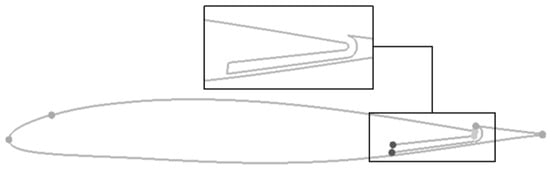
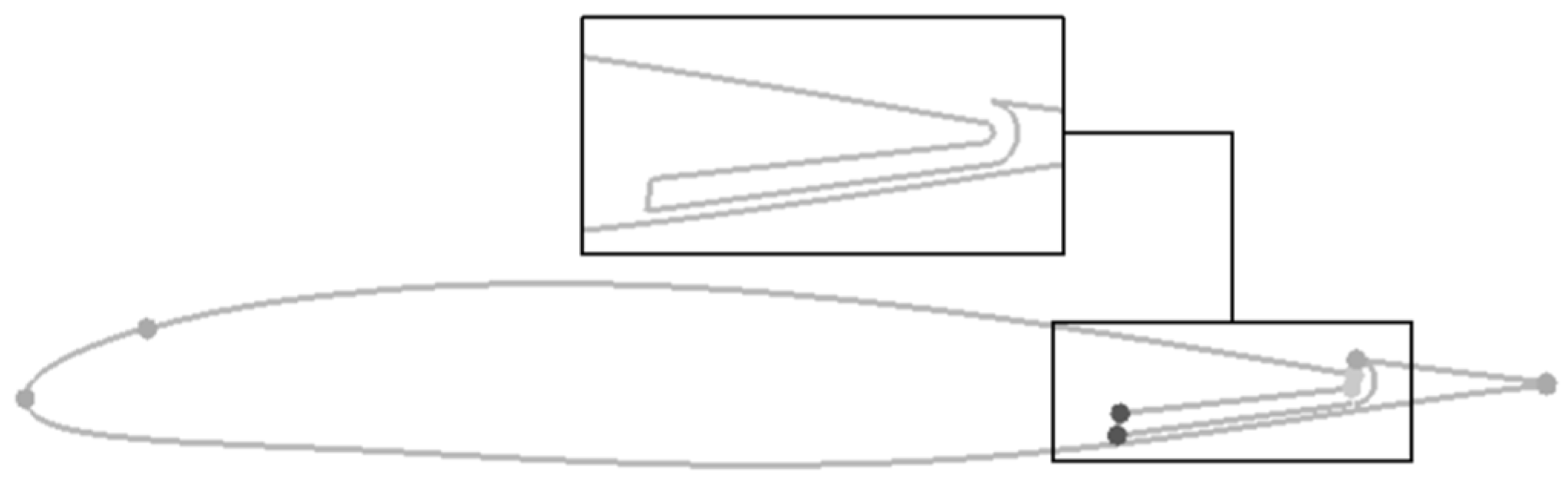
Figure 4.
The arrangement of the suction channel.
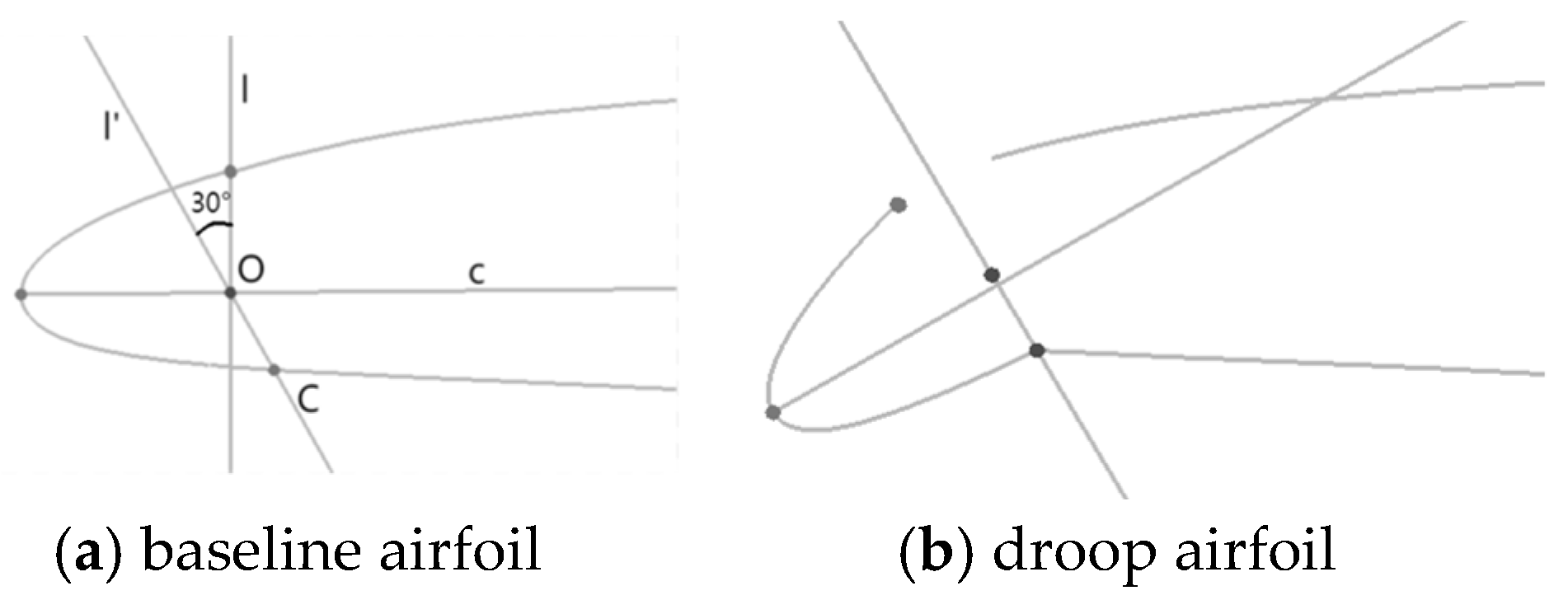
Rotating the vertical line I by 30° counterclockwise around the intersection point O of the vertical line and the chord, points I′ and C at the lower surface are obtained. Point C is the rotation center for the droop of the leading edge. The result after rotation is shown in Figure 5.
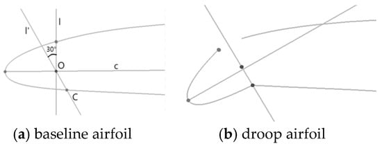
Figure 5.
The selection of the rotation point: (a) baseline airfoil and (b) droop airfoil.
The design principle of the external wall of the blowing channel is to reduce the concave amplitude at the corner, increase appropriately the curvature radius of the channel wall, reduce the flow separation in the channel, and reduce the loss of total pressure and energy, as shown in Figure 6.
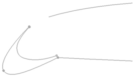
Figure 6.
Design of the external wall of the blowing channel.
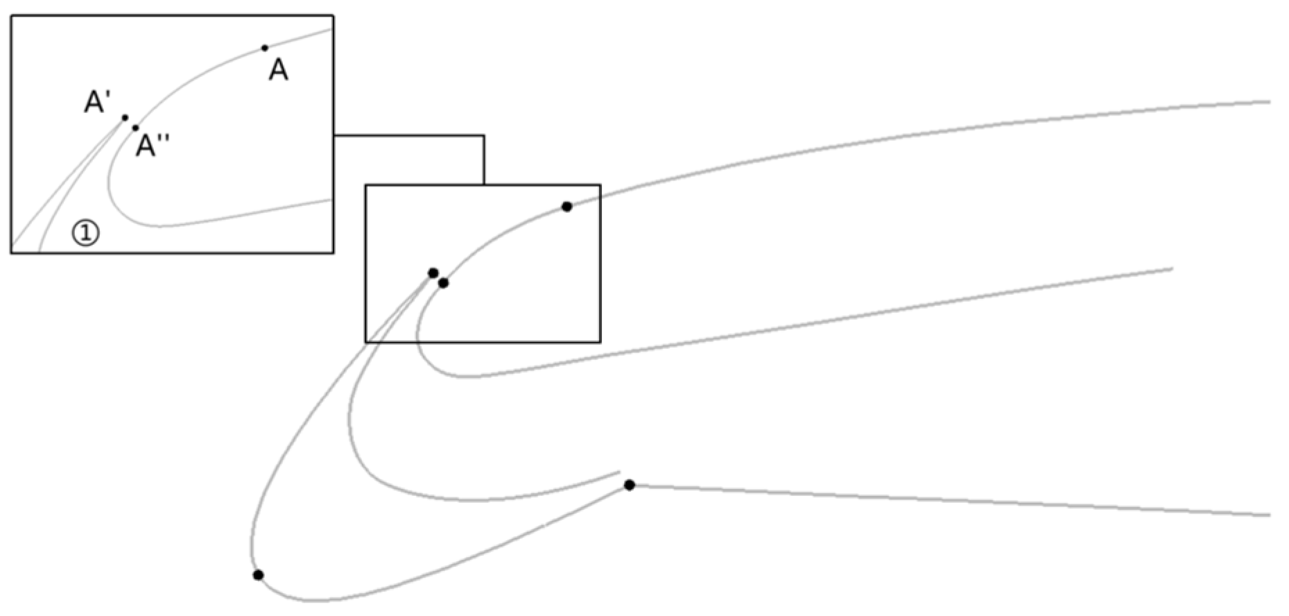
The size of the blowing slot is set to 0.3% c. The A point is the crossing point of line I and the upper surface of airfoil. The A′ point is translated 0.3% c along the vertical direction of the channel wall to obtain the A″ point. A′A″ is just the blowing slot. Extending the curves towards both sides through the A″ point, the upper surface of the airfoil and the inner wall of the channel are filled, respectively, as shown in Figure 7. When filling the upper surface, in addition to a smooth transition treatment, the curvature of the arc between A and A″ should also be appropriately increased to ensure that there will be no collision between the outer channel wall and arc AA″ in the recovery process of the leading edge. Finally, the remaining part of the blowing channel is filled according to the principle of contractive shape, including mainly the straight line BE and arc BB′ as illustrated in Figure 8, where point B is the crossing point of line I and the lower surface of blowing turb and point E is the end point of lower surface.

Figure 7.
Design of the inner wall of the blowing channel.
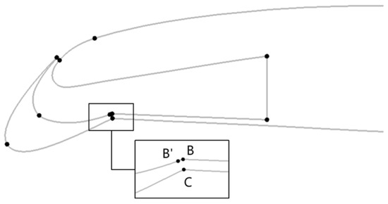
Figure 8.
Design for the rest of the wall of the blowing tube.
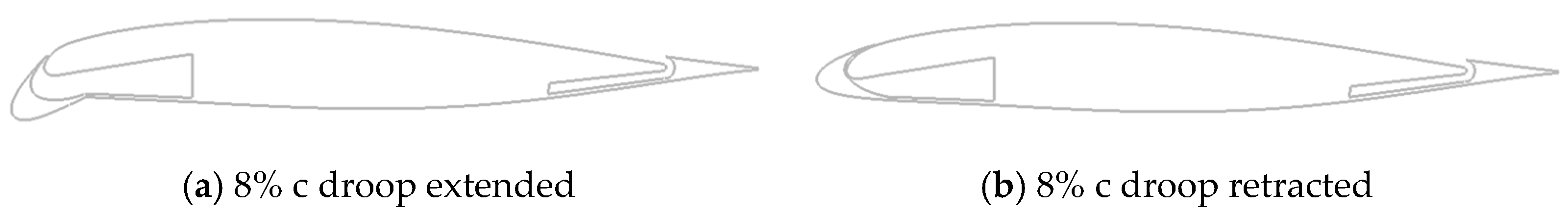
The droop and recovering states of the designed “CFJ + Droop” airfoil are shown in Figure 9. After being retracted, the head of the airfoil can be restored to the original state, and the original design characteristics can be maintained during high-speed cruise.
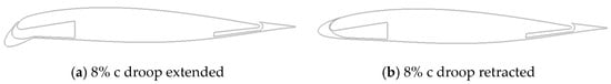
Figure 9.
The comparison of different statuses of the “CFJ + droop” airfoil: (a) 8% c droop extended and (b) 8% c droop retracted.
3. Results
3.1. Control Efficiency
3.1.1. Control Efficiency of the Leading-Edge Droop
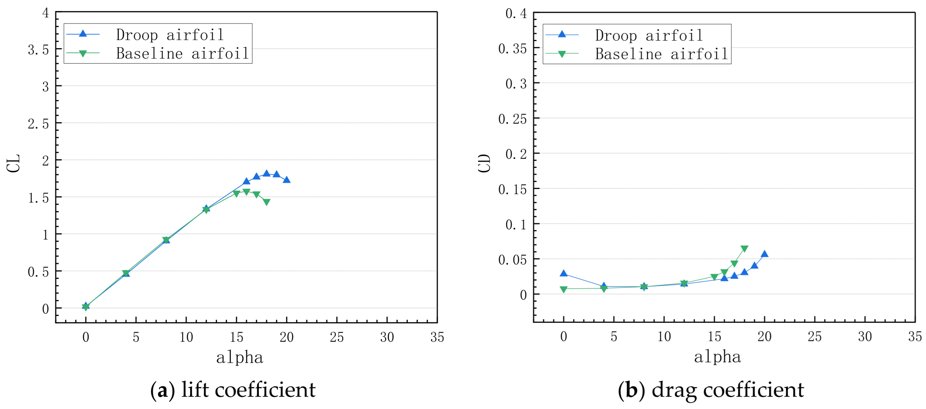
First, the gain effect of the leading-edge droop technique on the airfoil is analyzed with Ma = 0.2. The rotation point is selected at the 8% c location, and the deflection angle of the leading-edge droop is 30°. The moment reference point of the baseline airfoil is also used as the moment reference point for the droop airfoil. Figure 10 shows the comparison of aerodynamic force coefficients between the baseline airfoil and droop airfoil.
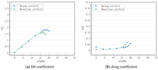
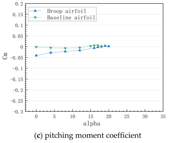
Figure 10.
Comparison of aerodynamic force coefficients for the baseline and droop airfoils: (a) lift coefficient, (b) drag coefficient, and (c) pitching moment coefficient.
Due to the increase of the equivalent leading-edge radius, the effect of the leading-edge droop is mainly reflected in delaying the stall angle and increasing the maximum lift coefficient. The stall angle of the droop airfoil increased from 16° to 18° relative to the baseline airfoil, and the maximum lift coefficient increased from 1.5772 to 1.8071. As for drag, it can be seen that the droop airfoil with a larger leading-edge radius will suffer a slightly larger pressure drag under the condition of a small angle. With the increase of the angle of attack, the drag coefficients of the two airfoils differ little. When approaching the stall angle, the increase of drag with the increasing angle of attack for the droop airfoil is smaller than that for the baseline airfoil. Further, it can be seen that the pitching-down moment coefficient of the baseline airfoil increases linearly with the increase of the angle, and it is in the longitudinally static stable state. With the increase of the angle, it enters the longitudinally static unstable state due to the separation at the trailing edge. Due to the larger curvature of the head, the droop airfoil has a larger pitching-down moment. With the increase of the angle, the pitching-down moment decreases approximately linearly, and the airfoil is in a statically unstable state.
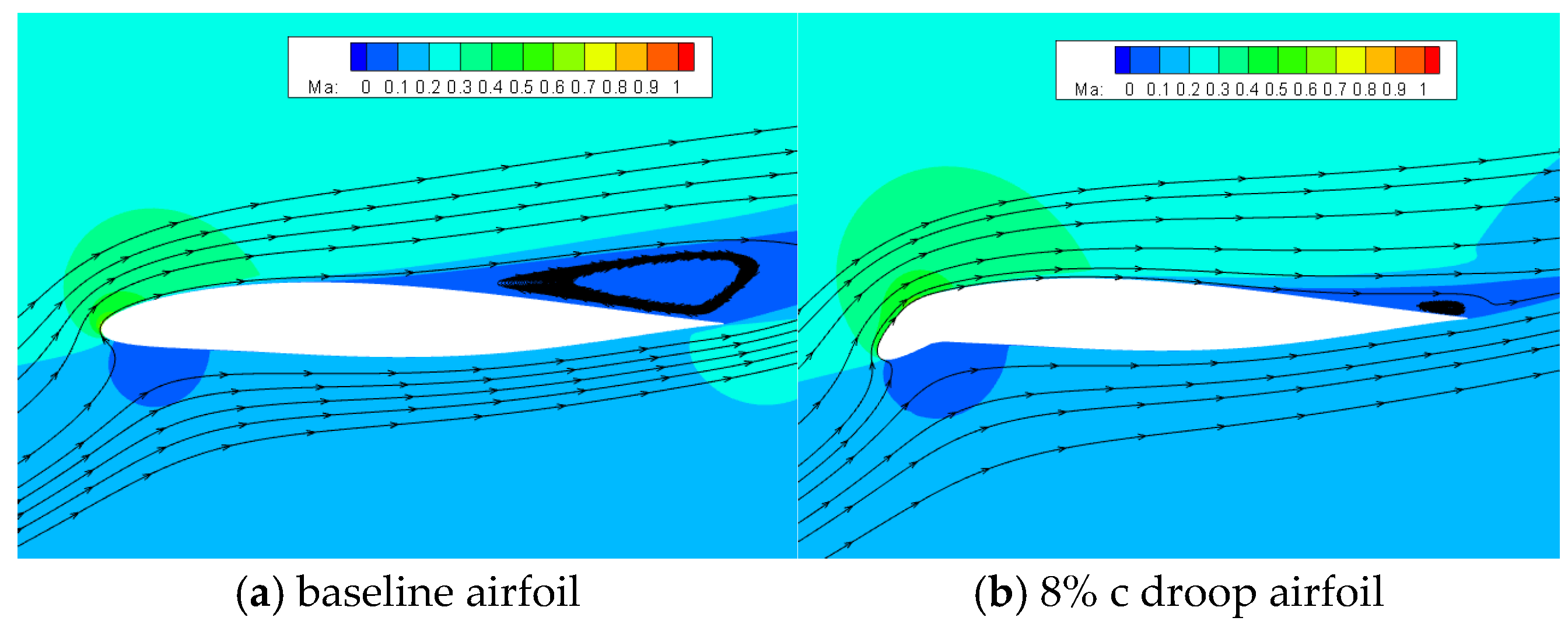
Figure 11 and Figure 12 show the contours of the pressure coefficient and Mach number as well as streamline plots for the baseline airfoil and droop airfoil at α = 18°. It can be seen that a large area of flow separation occurs at the trailing edge of the baseline airfoil, resulting in the stall phenomena. As for the droop airfoil, there is obviously a larger area of negative pressure and a slightly smaller peak value of negative pressure near the leading edge, forming a second suction peak in the transition region. The negative pressure peak of the air flow through the head is effectively reduced, and the adverse pressure gradient downstream is also decreased, delaying the flow separation and improving the aerodynamic characteristics at conditions of low speed and a large angle of attack.
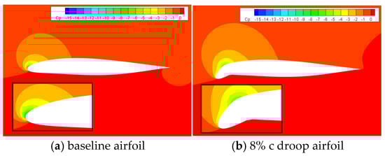
Figure 11.
Comparison of the pressure coefficient at α = 18°: (a) baseline airfoil and (b) 8% c droop airfoil.
Figure 12.
Comparison of the contours of the Mach number and streamlines at α = 18°: (a) baseline airfoil and (b) 8% c droop airfoil.
When the angle of attack increases to 20°, the flow separation is also generated at the trailing edge of the droop airfoil due to the inability to overcome an excessive adverse pressure gradient, and the stall mechanism is the same as that for the baseline airfoil. As shown in Figure 13, the separation area at the trailing edge of the droop airfoil is close to half of the airfoil surface, resulting in the airfoil stall.
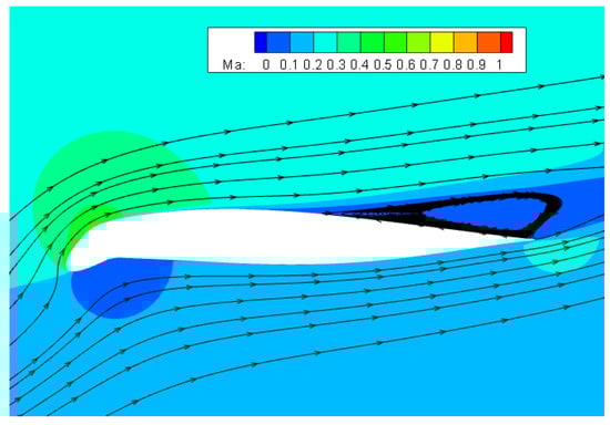
Figure 13.
The contours of the Mach number and streamlines at α = 20° for 8% c droop airfoil.
3.1.2. Control Efficiency of CFJ for Baseline Airfoil
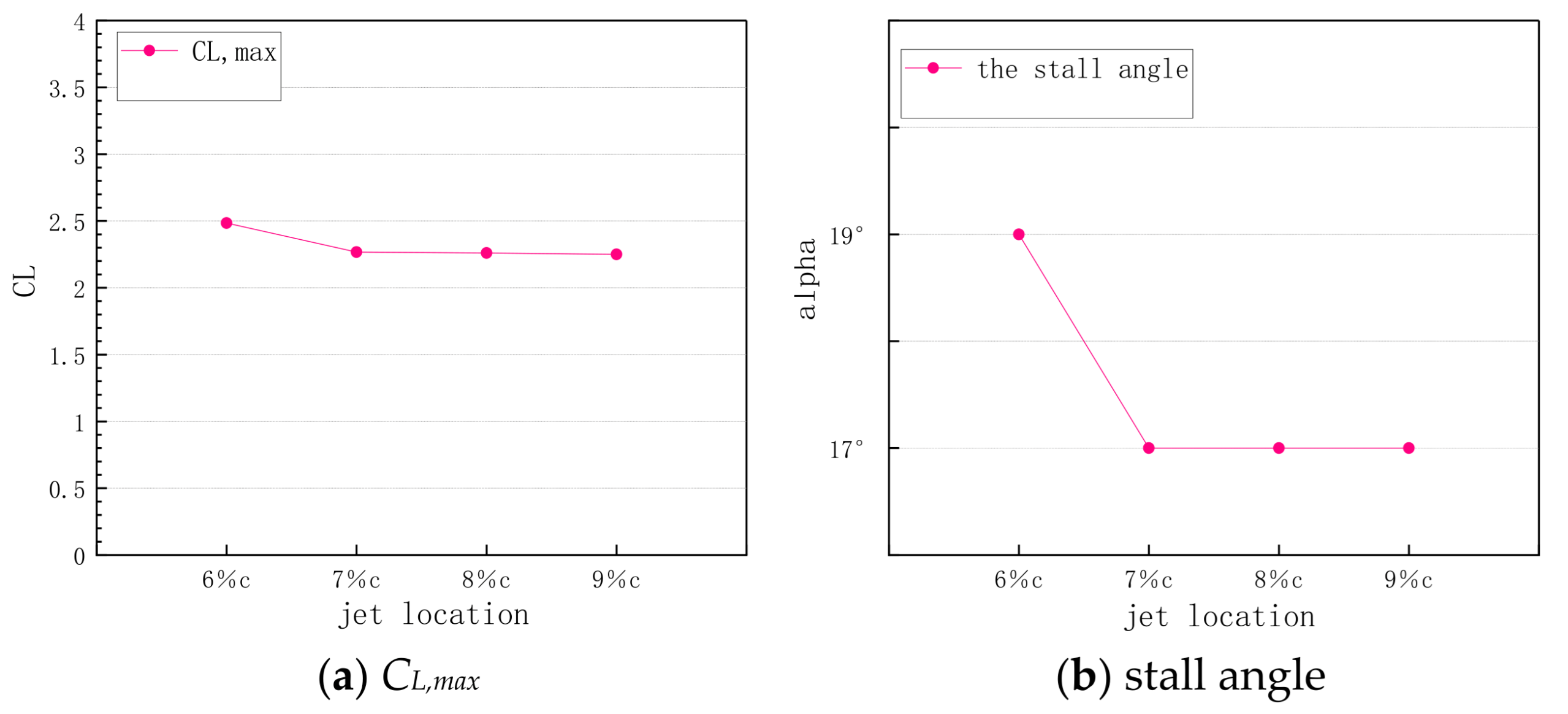
This section compares the stall angle and the corresponding aerodynamic coefficients with different locations of the blowing slot (6% c, 7% c, 8% c, and 9% c) to determine the optimal location of the blowing slot. The blowing momentum coefficient of the jet is about 0.1.
As seen in Figure 14, when the blowing slot position of the CFJ airfoil is close to the leading edge, the influence of the minor adjustment of this position is mainly reflected in the stall angle. The stall angle of the CFJ airfoil with a blowing slot position of 6% c is 19°, while the stall angle for the other three positions is 17°. As for the aerodynamic force coefficient, the CFJ airfoil with the blowing slot position of 6% c has a slightly higher maximum lift coefficient at the stall angle than the CFJ airfoils with the other three positions. The blowing slot position of the CFJ airfoil in this paper is selected as 6% c.
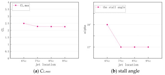
Figure 14.
Variation of CL,max and stall angle with blowing slot location for CFJ airfoil: (a) CL,max and (b) stall angle.
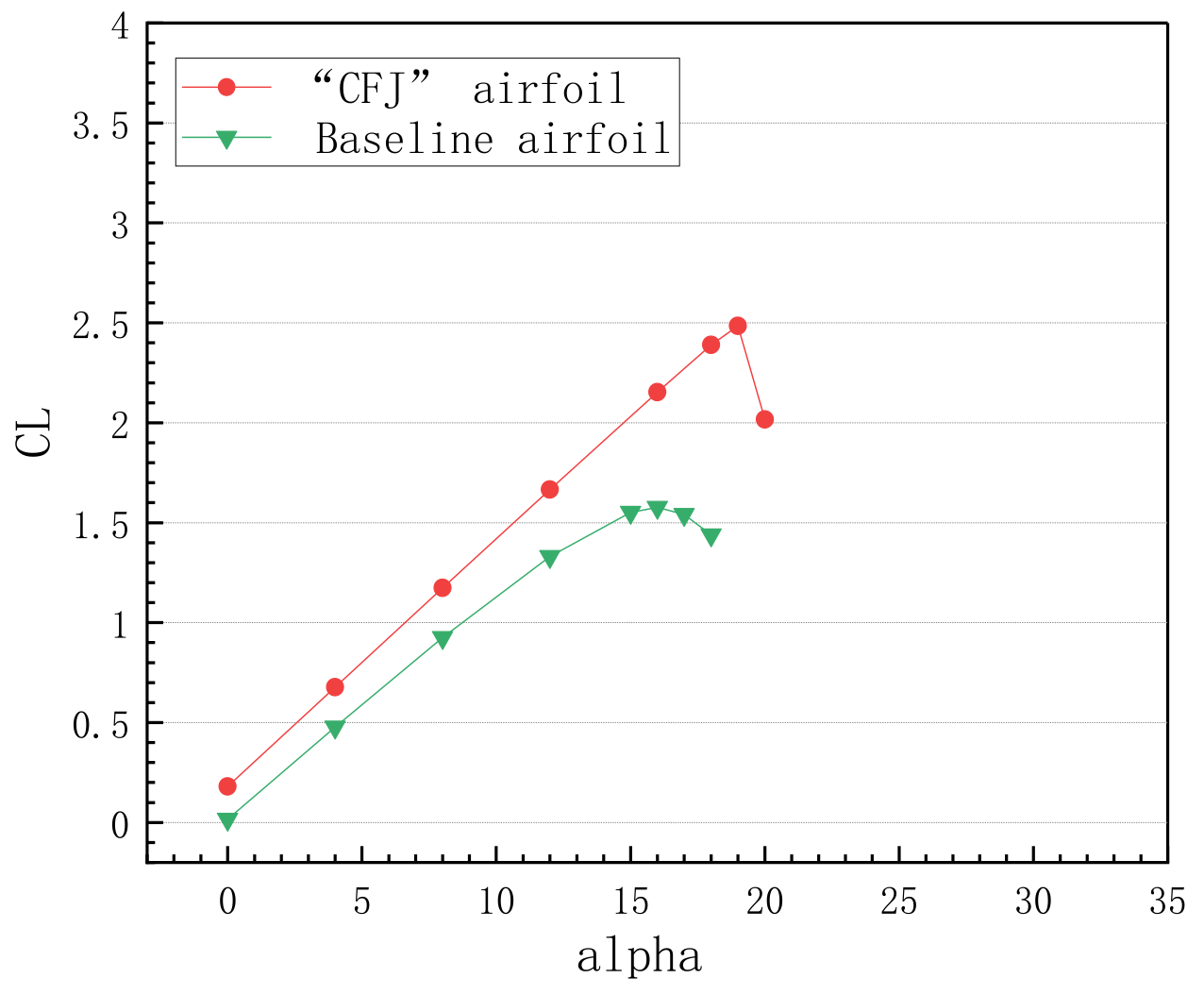
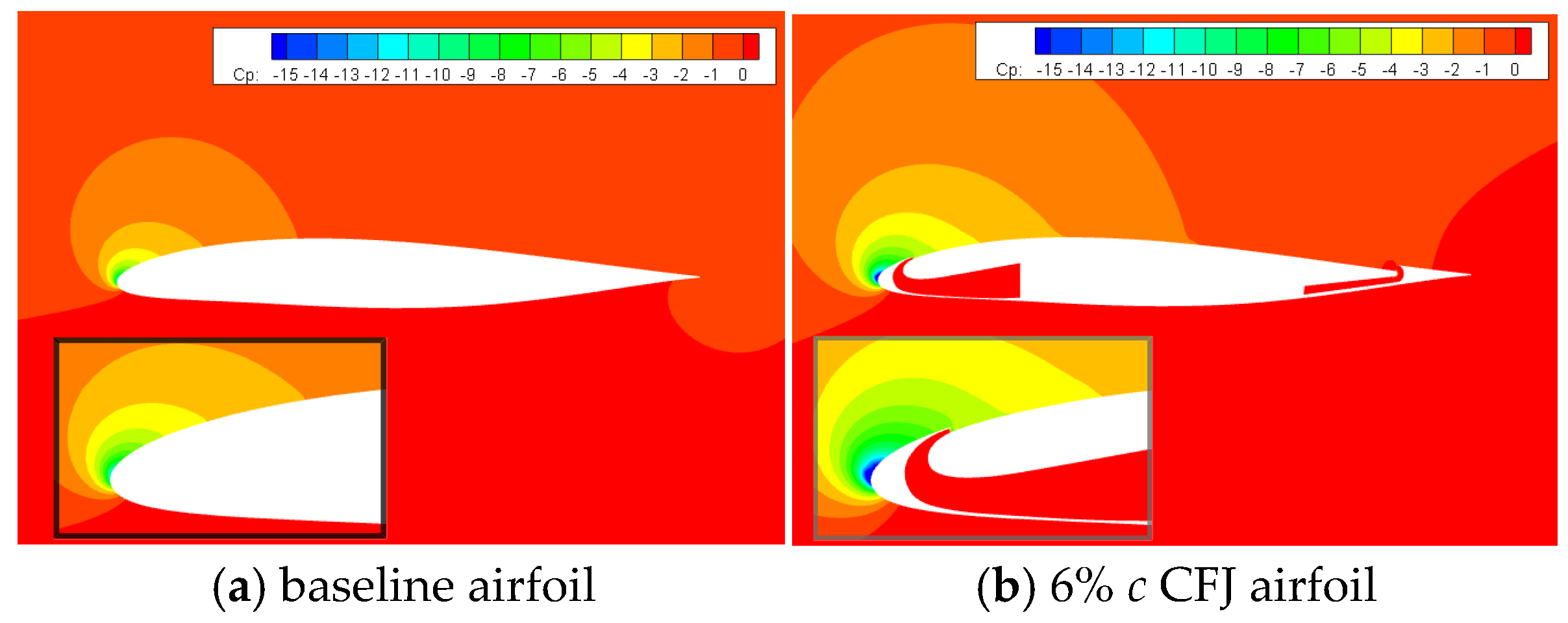
As seen from the results of the lift coefficients given in Figure 15, compared with the baseline airfoil, CFJ has a very obvious effect on lift enhancement. The lift line slope is increased, the stall angle is delayed from 16° to 19°, and the maximum lift coefficient is increased from 1.5772 to 2.4508. Figure 16 and Figure 17 show, respectively, the pressure and Mach-number contours for the CFJ airfoil and the baseline airfoil at the angle of attack of 18°. At this angle, the baseline airfoil has already stalled due to a large separation area at the trailing edge, while energy is continuously injected into the boundary layer for the CFJ airfoil to ensure that there is enough momentum to overcome the adverse pressure gradient, suppressing boundary layer separation. It can be clearly seen that the CFJ airfoil has a larger area of negative pressure and a larger peak value of negative pressure than the baseline airfoil.
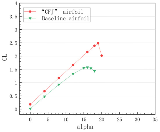
Figure 15.
Comparison of lift coefficients of the airfoil with and without CFJ.
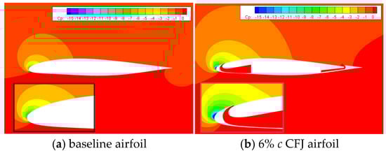
Figure 16.
The comparison of the contours of the pressure coefficient at α = 18° for different airfoils: (a) baseline airfoil and (b) 6% c CFJ airfoil.
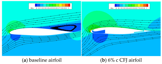
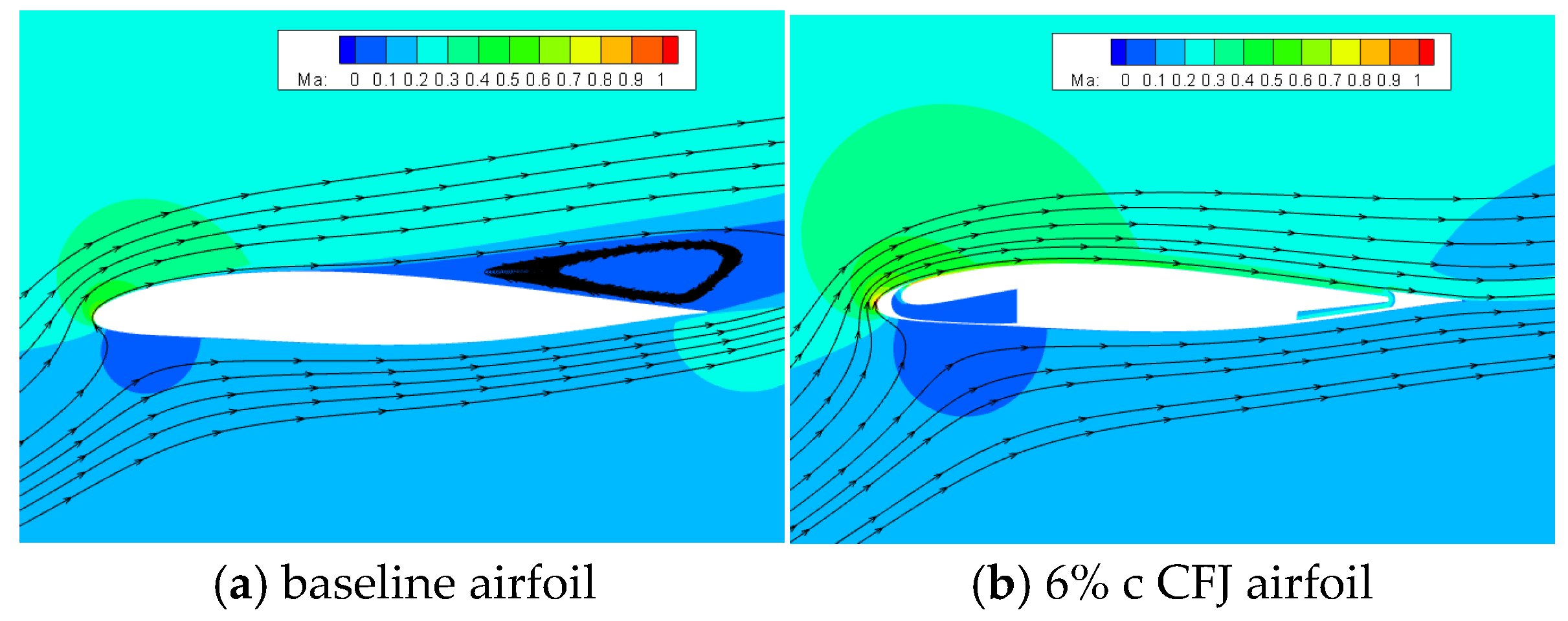
Figure 17.
Comparison of the contours of the Mach number and streamlines at α = 18° for different airfoils: (a) baseline airfoil and (b) 8% c CFJ airfoil.
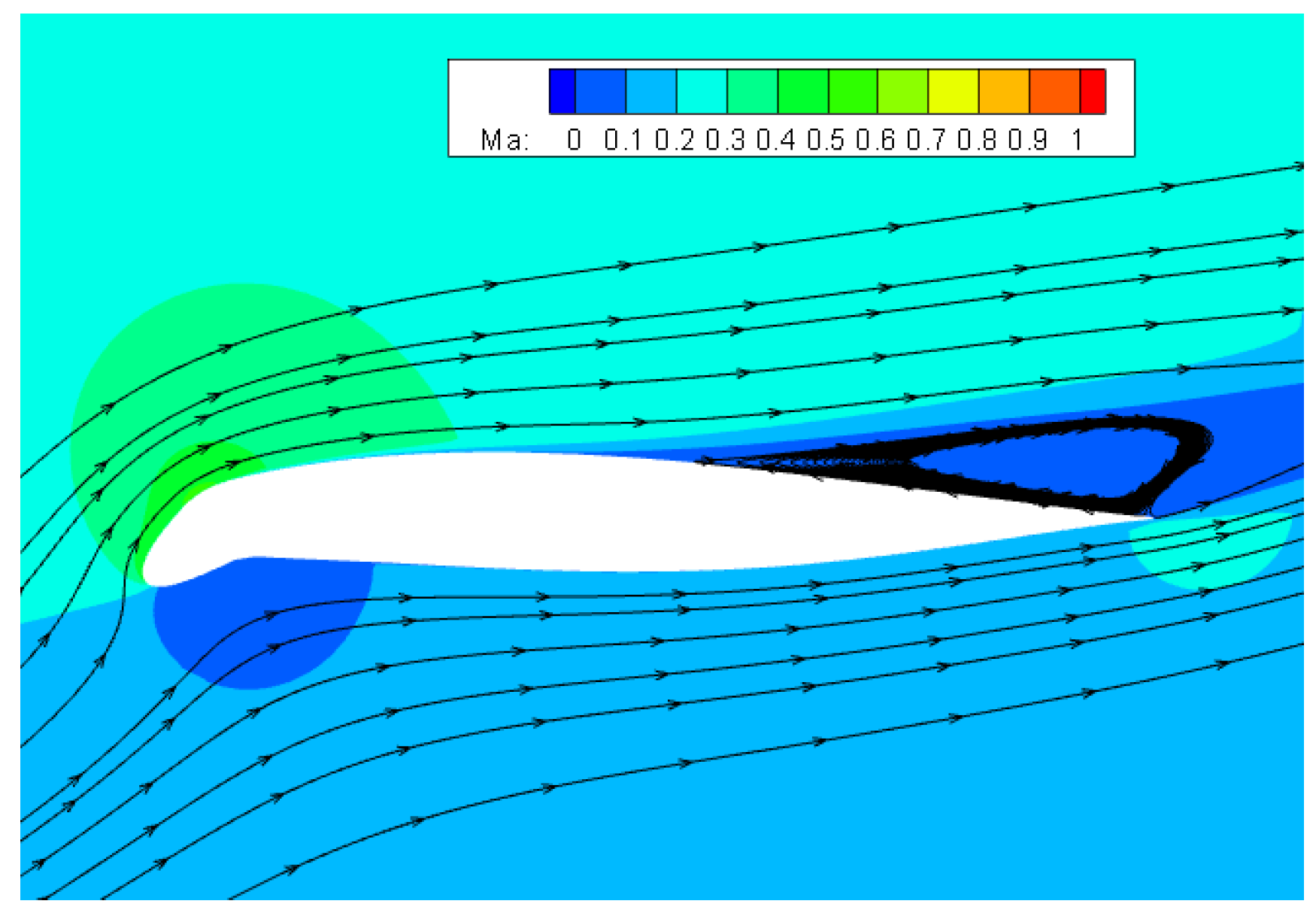
When the angle of attack increases to 20°, the CFJ airfoil stalls. According to the contours of the Mach number shown in Figure 18, the stall of the airfoil is caused by boundary layer separation upstream of the blowing slot (leading-edge separation). After the air flow bypasses the leading edge, it cannot maintain the attached state under the action of the strong adverse pressure gradient. The separation area continues to develop in the downstream direction, resulting in a low-speed separation vortex on the entire surface. Therefore, the CFJ airfoil suddenly stalls, and the static stability characteristics change abruptly. It can also be deduced that further increasing the mass flow rate will not improve the flow control effect. Compared with the baseline airfoil, although the addition of CFJ makes the airfoil circulation increase and the effects of the lift increase and drag reduction remarkable, the flow field above the airfoil changes dramatically in a short time, and the lift coefficient drops sharply once the CFJ airfoil reaches the stall angle. Nevertheless, due to the flow separation at the trailing edge, the flow field of the baseline airfoil changes gently, and its lift coefficient decreases more smoothly.
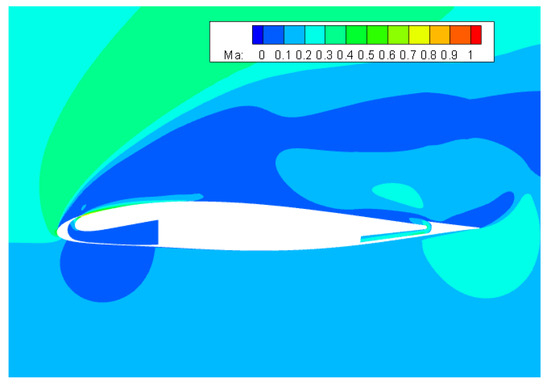
Figure 18.
The contours of the Mach number at α = 20° for CFJ airfoil.
3.1.3. Control Efficiency for “CFJ + Droop” Airfoil
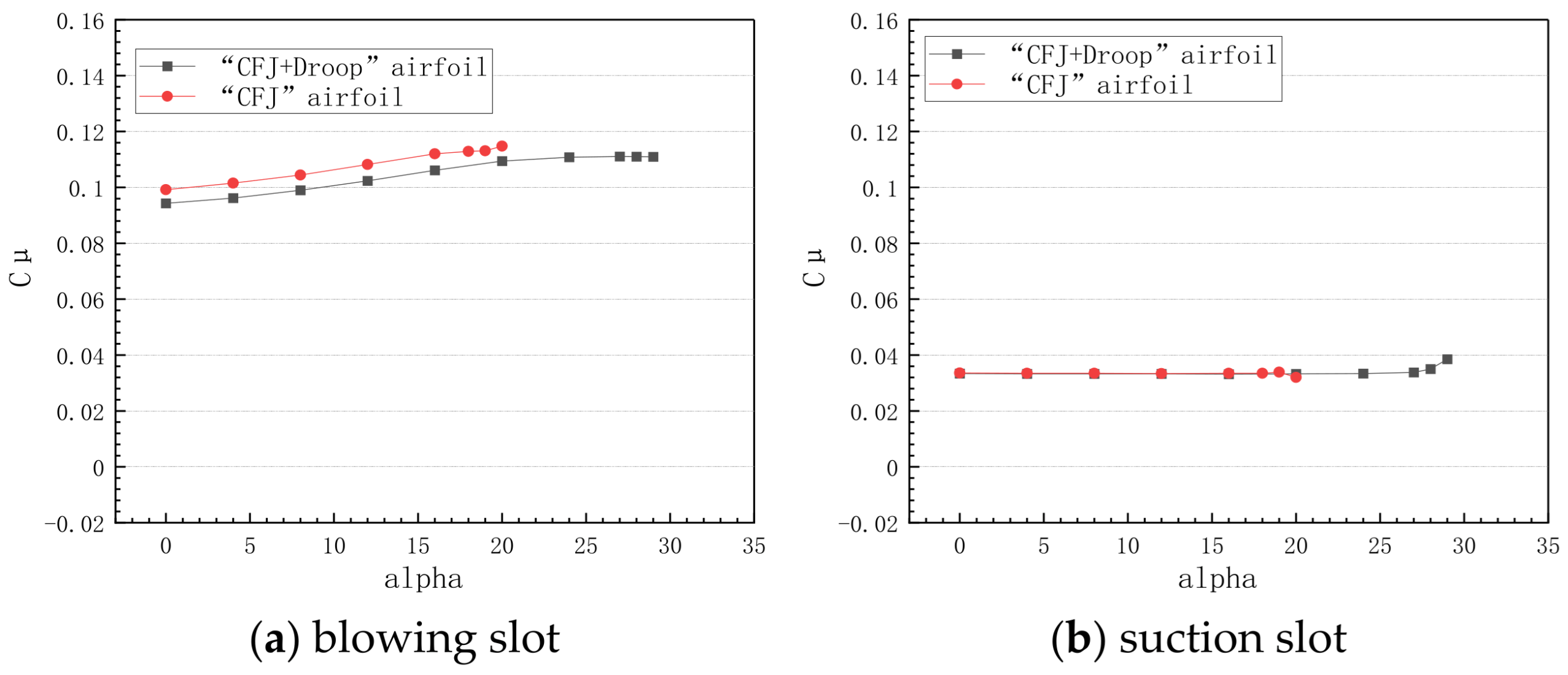
This section compares the CFJ airfoil and “CFJ + droop” airfoil, as shown in Figure 19. The sizes of the CFJ device, the internal channels, and the upper surface downstream of the blowing slot for the “CFJ + droop” airfoil are identical to those for the CFJ airfoil, with only the leading-edge droop treatment performed at the position of 6% c. Figure 19 shows the jet momentum coefficients for the two types of CFJ airfoils at the blowing and suction slots. It can be seen that at the same mass flow rate, there is almost no difference between the CFJ airfoil and the “CFJ + droop” airfoil at the suction slot. Because there is a larger negative pressure peak near the leading edge for the CFJ airfoil, which is more beneficial for the blowing in the blowing channel, the jet momentum coefficient of the CFJ airfoil will be slightly larger than that of the “CFJ + droop” airfoil at the blowing slot. The droop of the leading edge reduces the peak value of negative pressure at the airfoil head and weakens the adverse pressure gradient.
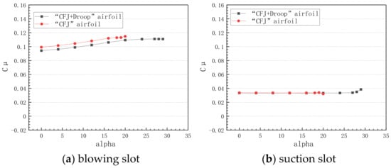
Figure 19.
Variation of the jet momentum coefficient with angle of attack at blowing/suction slot: (a) blowing slot and (b) suction slot.
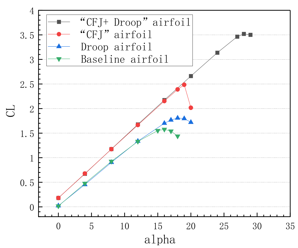
Figure 20 shows the lift coefficients of the baseline airfoil, droop airfoil, CFJ airfoil, and “CFJ + droop” airfoil. It can be obviously seen that the lift curve slope and zero lift angle of the “CFJ + droop” airfoil and CFJ airfoil are almost equal before the stall, but the “CFJ + droop” airfoil has a larger stall angle and maximum lift coefficient. The stall angle is delayed to 28°, and the maximum lift coefficient is increased to 3.4888. The characteristics at the conditions of low speed and a large angle of attack are significantly improved. When there is no CFJ, the leading-edge droop only increases the stall angle by 2°.
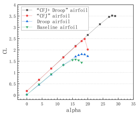
Figure 20.
Lift coefficient vs. angle of attack.
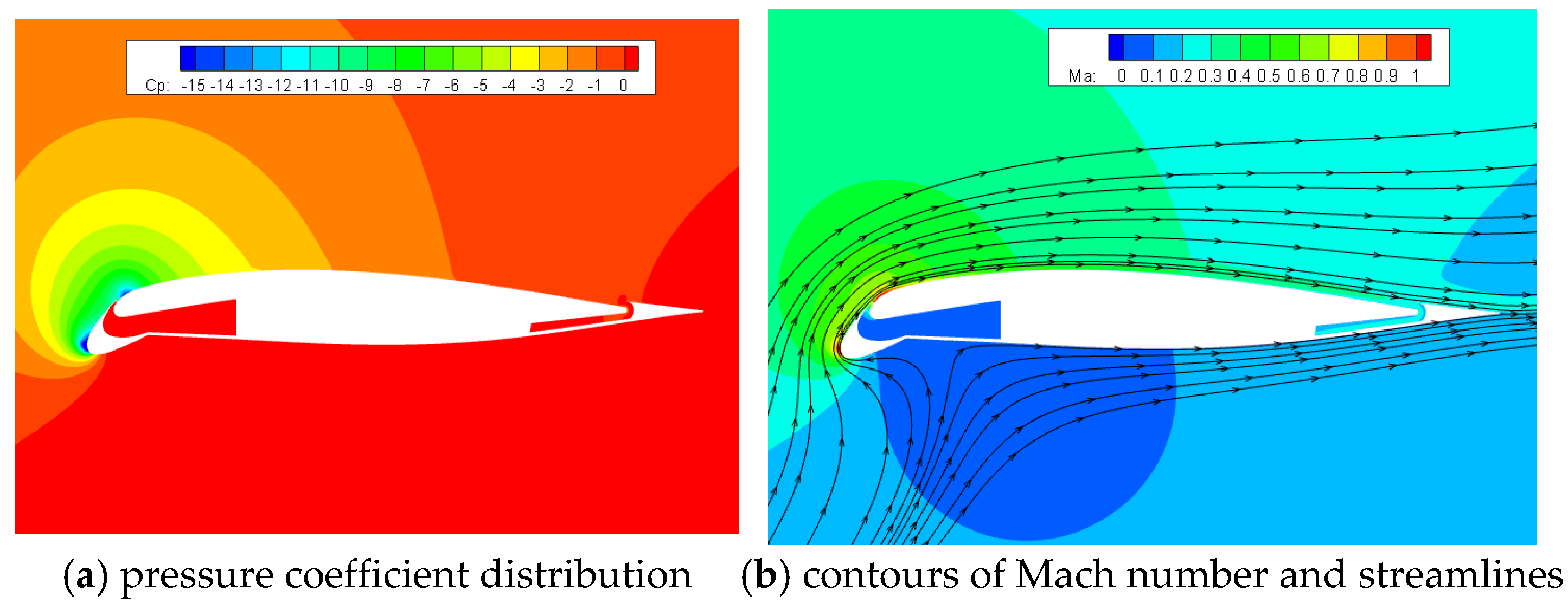
Figure 21 shows the pressure and Mach-number contours for the “CFJ + droop” airfoil at 27° when the stall angle has not been reached. Seen from the contours of pressure distribution, due to the application of the leading-edge droop, there are two peak regions of negative pressure at the head position, and the low-pressure area is large. Under the action of a CFJ, the trailing-edge separation is also effectively controlled. Seen from the perspective of the spatial flow field, even under the condition of α = 27°, the air flow at the leading edge can still keep attached, and there is no separation at the leading edge.
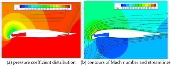
Figure 21.
The flow properties of “CFJ + droop” airfoil at α = 27°: (a) pressure coefficient distribution and (b) contours of Mach number and streamlines.
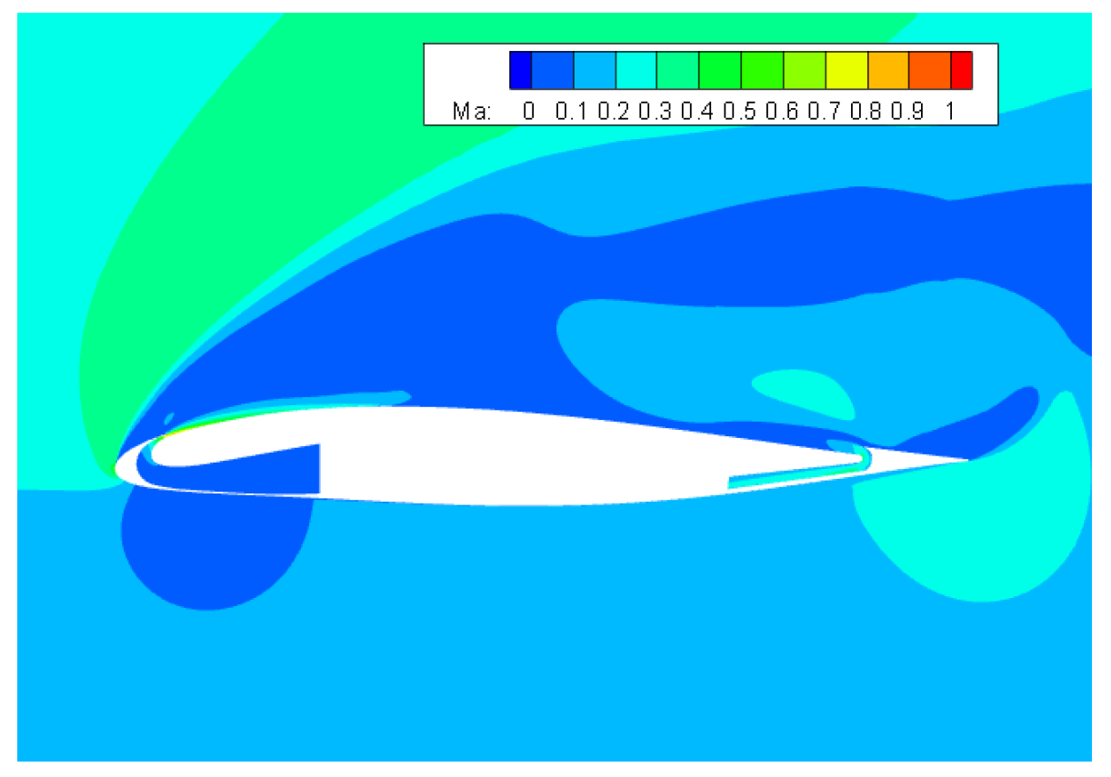
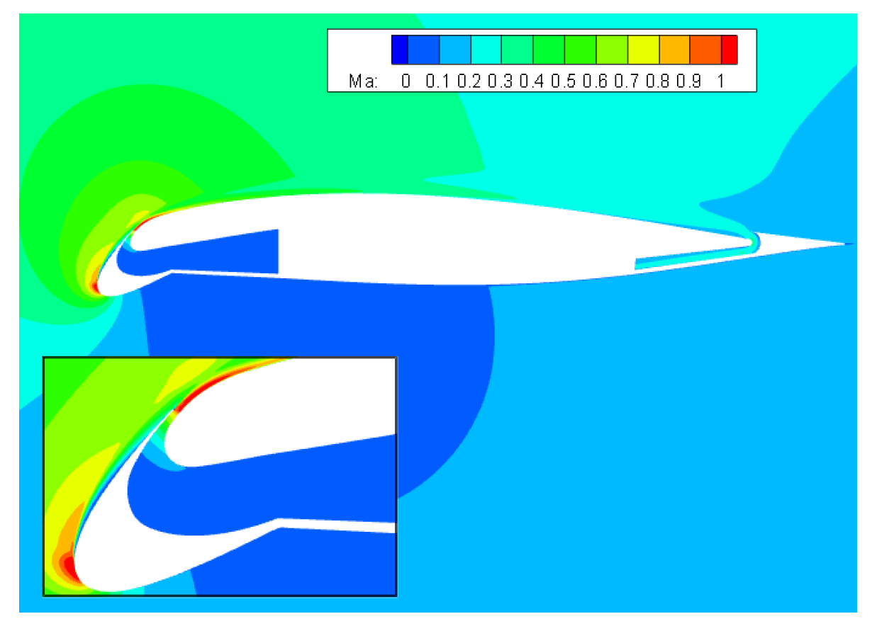
When the angle of attack increases to 29°, the “CFJ + droop” airfoil has stalled; the contours of the Mach number are shown in Figure 22. It can be seen that a small area of stall has appeared in the droop position of the head, indicating that there is a flow separation. Different from the CFJ airfoil, as the “CFJ + droop” airfoil has a larger leading-edge radius, the second peak area of negative pressure at the drooped corner makes the air flow with the separation trend reattached, and a larger low-speed separation area is not produced. Thus, when the angle of attack just reaches the stall angle, the lift curve will not drop rapidly. As the angle of attack increases continuously, the air flow cannot be attached, the stall region caused by the leading-edge separation will develop rapidly, and the lift will decrease rapidly.
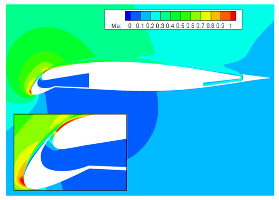
Figure 22.
The contours of the Mach number at α = 29° for “CFJ + droop” airfoil.
3.2. Analysis of the Effect Factors on the Aerodynamic Characteristics of “CFJ + Droop” Airfoil
3.2.1. The Location of Rotation Center
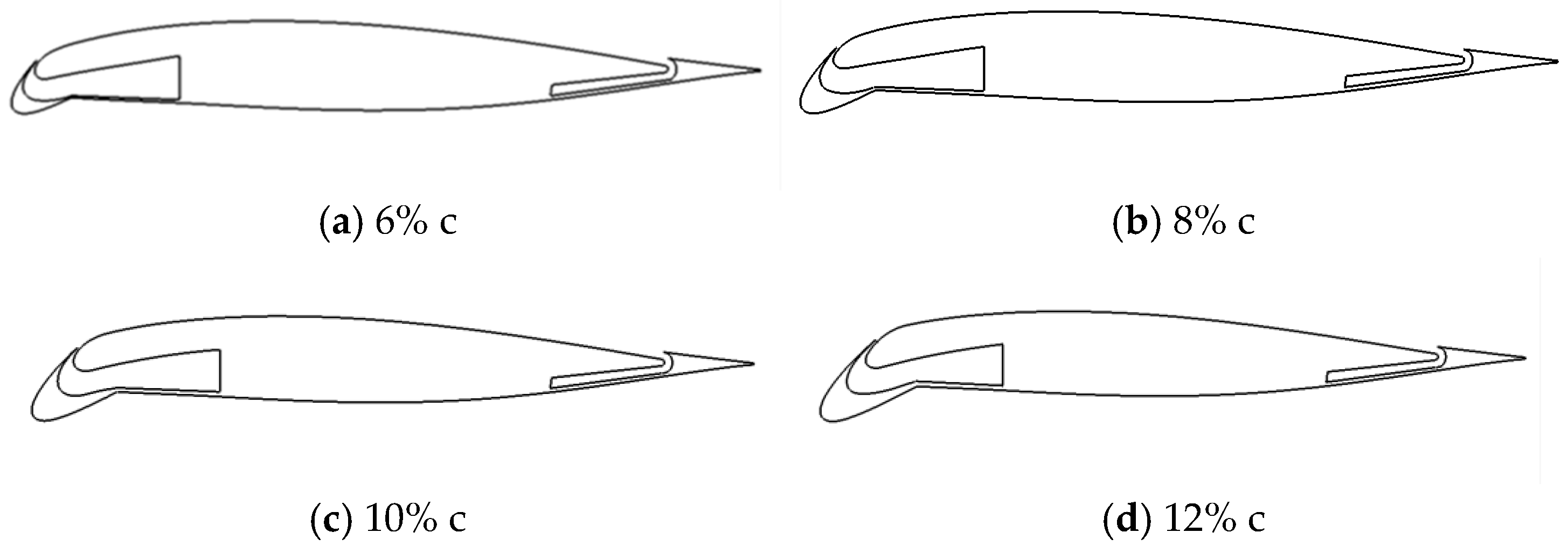
According to the design method mentioned above, the rotation points obtained by the vertical lines at different positions are different, resulting in different values for the leading-edge radius. The location of the rotation center needs to be discussed as a research variable. Here are “CFJ + droop” airfoils derived from the rotation of the leading edge by 30° around the rotation centers obtained by the vertical lines at the locations of 6% c, 8% c, 10% c, and 12% c, as shown in Figure 23.

Figure 23.
Comparison of “CFJ + droop” airfoils with different locations of rotation center: (a) 6% c, (b) 8% c, (c) 10% c, and (d) 12% c.
Figure 24 shows the comparison of lift coefficients of four “CFJ + droop” airfoils with different rotation centers, where the sizes of the blowing slot are all 0.3% c, the mass flow rate is set to 3 kg/s, and the corresponding jet momentum coefficient at the blowing slot is about 0.1. It can be seen that the position of the rotation center has almost no effect on the lift coefficient of the airfoil. There are only slight differences in the stall angle and the maximum lift coefficient. The stall angles of “CFJ + droop” airfoils with the rotation centers at the positions of 6% c and 8% c are 28°. The corresponding maximum lift coefficients are 3.4489 and 3.5198, respectively. The stall angles of “CFJ + droop” airfoils with the rotation centers at the positions of 10% c and 12% c are 29°, and the corresponding maximum lift coefficients are 3.5834 and 3.6323, respectively.
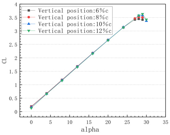
Figure 24.
Lift coefficients of “CFJ + droop” airfoils with different rotation centers.
The lift coefficients of the four airfoils mentioned above are relatively close, and the rotation center needs to be selected according to the application of practical engineering. If the rotation center is too far forward, the droop area at the leading edge is too small, and the leading-edge radius does not increase significantly, affecting the delay degree of the stall angle. If the position of the rotation center is too far back, the airfoil obtained is not beneficial to the placement of internal support structures, pipes, and other components. This paper uses the rotation center obtained by the vertical line at the location of 8% c.
3.2.2. The Droop Angle
The difference in the droop angle of the leading edge will also lead to a difference in the leading-edge radius, and thus the droop angle needs to be discussed as a variable. On the basis of the vertical line at the location of 8% c, CFJ airfoils with droop angles of 10°, 20°, and 30° are obtained, respectively, according to the design method mentioned above, as shown in Figure 25.
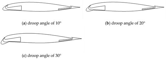
Figure 25.
Airfoils with different droop angles: (a) droop angle of 10°, (b) droop angle of 20°, and (c) droop angle of 30°.
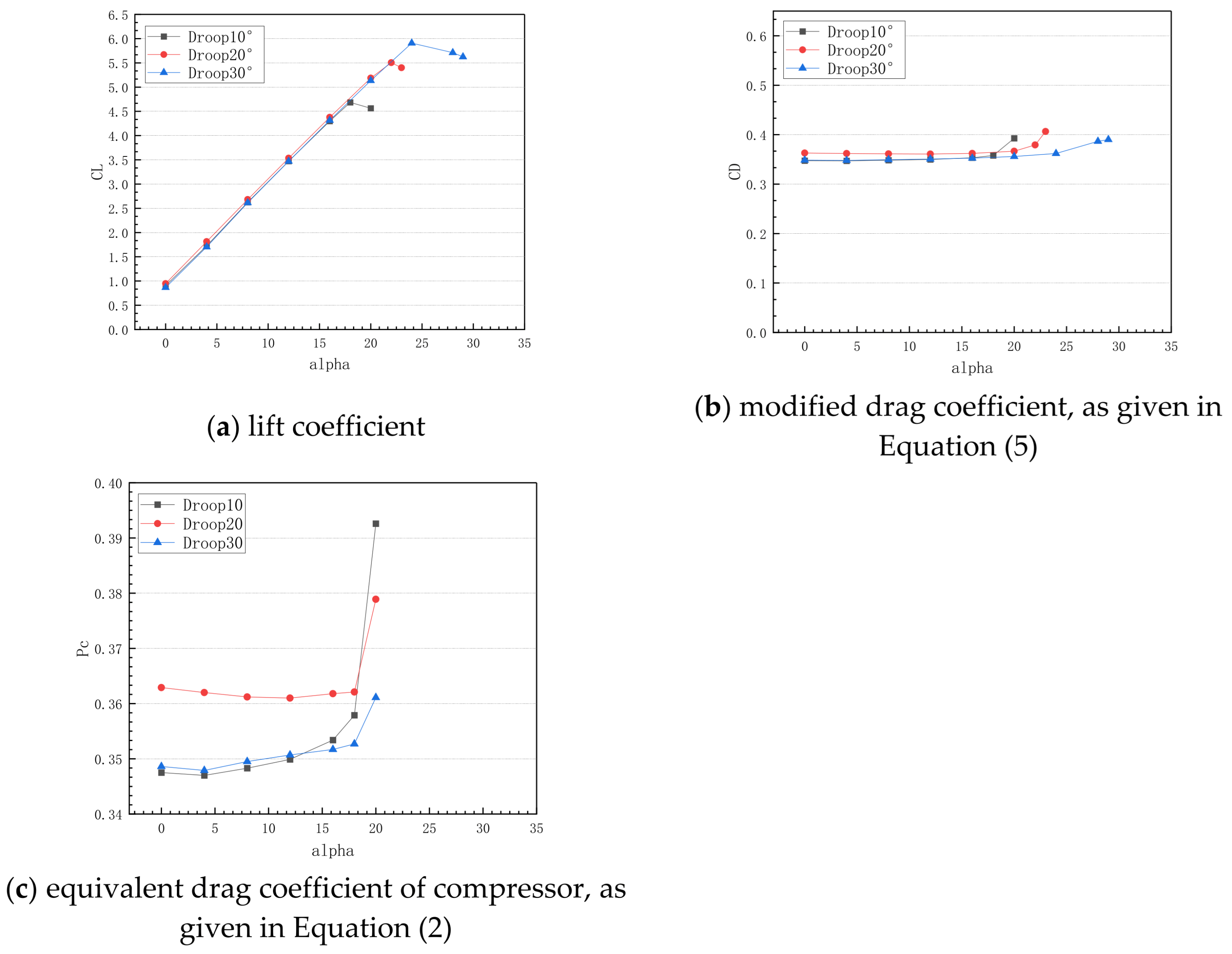
Figure 26 shows the aerodynamic force coefficient curves for “CFJ + droop” airfoils with three different droop angles, and the mass flow rate is fixed at 2 kg/s in the calculation. The larger the droop angle, the larger the curvature radius at the leeward surface of the airfoil will be, being beneficial to reducing the negative pressure peak and pressure gradient as well as delaying the stall angle. As seen from the curves of lift coefficients, the lift line slopes of the three airfoils are close before the stall. With an increase in the angle of attack, CFJ airfoils with droop angles of 10° and 20° reach stall at 18° and 22°, and the corresponding maximum lift coefficients are 5.0151 and 5.8889, respectively. A CFJ airfoil with a droop angle of 30° can increase the stall angle to 24°, and the maximum lift coefficient is increased to 6.3557. For the drag coefficient curves, it can be seen that the drags of the three airfoils are close before the stall. The drag values of the airfoils with droop angles of 10° and 20° almost coincide, while that with the droop angle of 30° is slightly less than those with the other two angles. Figure 26c depicts the power consumption curves of the pressurization device placed inside the wing. Obviously, the power coefficient is very high in comparison to the drag coefficient of the original airfoil, as shown in Figure 10. The comparative analysis shows that power consumption increases slightly with the increase of the angle of attack before the stall angle and increases rapidly after the stall angle is reached. This fact is due to the gradual increase of lift with increasing angle of attack. To maintain or increase lift, the system needs to consume more energy to drive the airfoil to a larger angle of attack. With an increase in the droop angle, its energy consumption also increases, as the increase of the droop angle will promote the formation of flow separation on the airfoil surface, affecting the interaction between the jet and the main stream and further increasing the drag of the airfoil. In order to overcome the drag increment, the pressurization device needs to consume more energy.
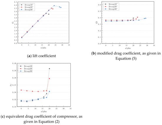
Figure 26.
Comparison of aerodynamic force coefficients of airfoils with different droop angles: (a) lift coefficient, (b) modified drag coefficient, and (c) equivalent drag coefficient of compressor.
3.2.3. Influence Law of Mass Flow Rate
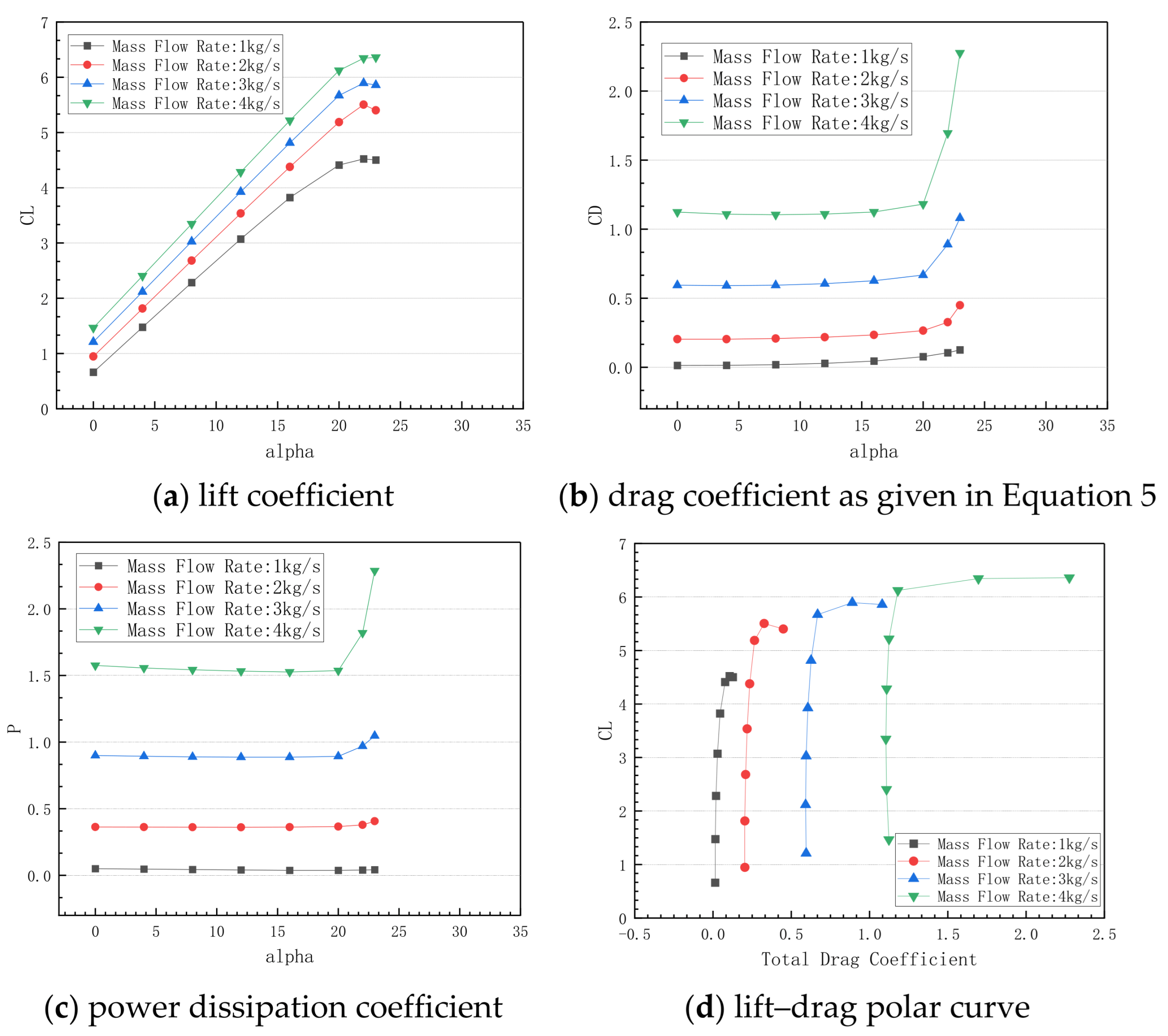
Figure 27 gives the comparison of aerodynamic force coefficients of “CFJ + droop” airfoils with different mass flow rates when the leading-edge droop angle is 20°. It can be seen that with an increase in the mass flow rate, the lift coefficient increases with the increase of circulation brought by the jet. The drag coefficient of the “CFJ + droop” airfoil presents a complicated behavior due to the change of jet thrust as well as the location and range of the low-pressure area. With a large mass flow rate, negative drag may occur at small angles of attack. However, as the angle of attack reaches the stall angle, the drag coefficient increases rapidly. Its power consumption shows a nonlinear increase trend with the increase of mass flow rate. Before the stall angle of attack is reached, the power consumption is relatively stable, as the camber between the blowing slot and the suction slot of the “droop” airfoil changes little. As the angle of attack increases, the change in pressure gradient is small. As seen from the lift–drag pole curves, the lift–drag ratio of the “CFJ + droop” airfoil decreases slightly with the increase in the mass flow rate. The smaller the mass flow rate, the larger the lift–drag ratio. The larger the mass flow rate, the larger the maximum lift coefficient near stall, with the lift–drag ratio not decreasing significantly.
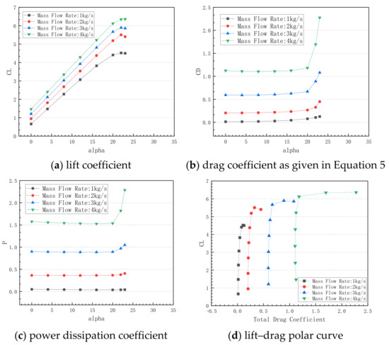
Figure 27.
Aerodynamic force coefficients vs. mass flow rate: (a) lift coefficient, (b) drag coefficient, (c) power dissipation coefficient, and (d) lift–drag polar curve.
4. Conclusions
In this paper, leading-edge droop technology and CFJ technology are successfully combined and applied to the design of thin airfoils, and an innovative design scheme, “CFJ + droop”, is proposed under the consideration of overcoming the defects of a complex set of mechanical devices common in passive control and the destruction of stealth performance common in active control. By precisely controlling the mechanical rotation around the rotation center, the free droop and recovery of the leading-edge part are realized, thus creating a CFJ airfoil with a very large lift suitable for situations of low speed and large angles of attack with stealth performance during high-speed cruise maintained. In detail, different types of airfoils are discussed in low-speed situations and large angles of attack, and their stall characteristics and flow mechanisms are analyzed; the main conclusions can be summarized as follows:
- (1)
- The results show that the control role of the droop of the leading edge is to increase the radius of the leading edge, then the negative pressure peak at the head, as well as the following adverse pressure gradient, is reduced; thus, the flow separation is delayed, which could greatly extend the stall angle. The stall for droop-head airfoils is the trailing-edge separation.
- (2)
- The CFJ approach injects high momentum flow into the boundary layer and postpones the trailing-edge separation, increasing the circulation of the airfoil, which could generate a higher lift. When the mass flow supply is enough, the stall of a CFJ airfoil is due to the leading-edge separation in an extremely high adverse-pressure gradient.
- (3)
- Droop technology, in conjunction with CFJ technology, inherits both merits and extends the stall angle to an even higher value, generating more lift as the mass flow of the CFJ increases.
- (4)
- The advantage of the “CFJ + droop” airfoil in trimming drag also highlights further its engineering application value. The power consumption of the airfoil with this simple droop device and CFJ is quite high; future work should be to reduce overall costs by optimizing the height and location of the slot and the shape of the duct.
For obtaining better control effects of the newly developed technique with the CFJ and variable camber, the following important parameters are recommended for the design of a “CFJ + droop” airfoil: the rotation center should be selected at an 8% c location from the leading edge, the droop angle should be set to 30°, and the jet size should be set to 0.3% c. The power consumption level of the new technology is very high, showing a trend of non-linear growth with the mass flow rate. How to control the mass flow rate for best achieving the goal is the next research emphasis.
Author Contributions
Conceptualization, J.J., P.Y. and B.W.; methodology, J.J.; software, Q.W. and S.N.; validation, C.C.; data curation, J.J.; writing—original draft preparation, J.J. and C.C.; writing—review and editing, S.N.; visualization, Q.W.; supervision, P.Y. All authors have read and agreed to the published version of the manuscript.
Funding
This research was funded by the Natural Science Basic Research Plan in Shaanxi Province of China (no. 2019JQ-912), and the National Natural Science Foundation of China (no. 11802234).
Data Availability Statement
All data used are included in the references.
Conflicts of Interest
The authors declare no conflicts of interest.
References
- Kadivar, E.; Timoshevskiy, M.V.; Nichik, M.Y.; El Moctar, O.; Schellin, T.E.; Pervunin, K.S. Control of unsteady partial cavitation and cloud cavitation in marine engineering and hydraulic systems. Phys. Fluids 2020, 32, 052108. [Google Scholar] [CrossRef]
- Zaresharif, M.; Ravelet, F.; Kinahan, D.J.; Delaure, Y. Cavitation control using passive flow control techniques. Phys. Fluids 2021, 33, 121301. [Google Scholar] [CrossRef]
- Collis, S.S.; Joslin, R.D.; Seifert, A.; Theofilis, V. Issues in active flow control: Theory, control, simulation, and experiment. Prog. Aerosp. Sci. 2004, 40, 237–289. [Google Scholar] [CrossRef]
- Jie, L.; Zhibin, G.; Heng, Z.; Jing, J. Numerical investigation of powered high-lift model with externally blown flap. J. Aircr. 2017, 54, 1539–1551. [Google Scholar] [CrossRef]
- Wierach, P.; Petersen, J.; Sinapius, M. Design and Experimental Characterization of an Actuation System for Flow Control of an Internally Blown Coanda Flap. Aerospace 2020, 7, 29. [Google Scholar] [CrossRef]
- Justiniano, E.; Mainka, G.E.; Brown, L.M.; Kutz, D.M.; White, E.B.; Van Dam, C.P.; Sheida Hosseini, S. Microjet Flow Control on an Airfoil Flap: Particle Image Velocimetry Characterization. AIAA J. 2024, 62, 4087–4100. [Google Scholar] [CrossRef]
- Jentzsch, M.; Taubert, L.; Wygnanski, I. Using sweeping jets to trim and control a tailless aircraft model. AIAA J. 2019, 57, 2322–2334. [Google Scholar] [CrossRef]
- Warsop, C.; Crowther, W.J. Fluidic flow control effectors for flight control. AIAA J. 2018, 56, 3808–3824. [Google Scholar] [CrossRef]
- Liu, R.; Lin, R.; Lian, G.; Xue, S.; Lin, Q. Multichannel plasma synthetic jet actuator driven by Marx high-voltage generator. AIAA J. 2021, 59, 3417–3430. [Google Scholar] [CrossRef]
- Liu, R.; Lin, R.; Lian, G.; Xue, S.; Lin, Q. Flow separation control over an airfoil using plasma co-flow jet. AIAA J. 2022, 60, 2195–2206. [Google Scholar] [CrossRef]
- Mahdavi, H.; Mani, M.; Abdollahi, R. An experimental investigation of the unsteady counter-flow generated by a DBD plasma actuator for flow control. Eur. Phys. J. Plus 2024, 139, 550. [Google Scholar] [CrossRef]
- Bharghava, D.S.N.; Jana, T.; Kaushik, M. A survey on synthetic jets as active flow control. Aerosp. Syst. 2024, 7, 435–451. [Google Scholar] [CrossRef]
- Zha, G.C.; Paxton, C.A. A Novel Airfoil Circulation Augment Flow Control Method Using Co-Flow Jet. In Proceedings of the 2nd AIAA Flow Control Conference, Portland, OR, USA, 28 June–1 July 2004. [Google Scholar]
- Zha, G.C.; Gao, W.; Paxton, C.D. Jet effects on co-flow jet airfoil performance. AIAA J. 2007, 45, 1222–1231. [Google Scholar] [CrossRef]
- Lefebvre, A.; Dano, B.; Difronzo, M. Performance of a Co-Flow Jet Airfoil with Variation of Mach Number; AIAA 2013-0490. In Proceedings of the 51st AIAA Aerospace Sciences Meeting Including the New Horizons Forum and Aerospace Exposition, Dallas, TX, USA, 7–10 January 2013. [Google Scholar]
- Sun, Y.; Qian, Y.; Gao, Y.; Wang, T.; Wang, L. Stall control on the wind turbine airfoil via the single and dual-channel of combining bowing and suction technique. Energy 2024, 290, 130224. [Google Scholar] [CrossRef]
- Greenblatt, D.; Williams, D.R. Flow control for unmanned air vehicles. Annu. Rev. Fluid Mech. 2022, 54, 383–412. [Google Scholar] [CrossRef]
- Preey, M.L.; Mueller, T.J. Leading and trailing edge flaps on a low Reynolds number airfoil. J. Aircr. 1987, 24, 653–659. [Google Scholar]
- Sodja, J.; Martinez, M.J.; Simpson, J.C.; De Breuker, R. Experimental evaluation of a morphing leading edge concept. J. Intell. Mater. Syst. Struct. 2019, 30, 2953–2969. [Google Scholar] [CrossRef]
- Kintscher, M.; Wiedemann, M.; Monner, H.P. Design of a smart leading edge device for low speed wind tunnel tests in the European project SADE. Int. J. Struct. Integr. 2011, 2, 383–405. [Google Scholar] [CrossRef]
- Vasista, S.; Riemenschneider, J.; Van Dekamp, B. Evaluation of a compliant droop-nose morphing wing tip via experimental tests. J. Aircr. 2017, 54, 519–534. [Google Scholar] [CrossRef]
- Lu, W.S.; Tian, Y.; Liu, P.Q. Aerodynamic performance of GAW-1 airfoil leading-edge and trailing-edge variable camber. Acta Aeronaut. Sin. 2016, 52, 437–450. (In Chinese) [Google Scholar]
- He, M.; Zhang, L.; Zhao, L. Research on Stall Characteristics of Droop Leading Edge Combined with Internal-blowing Flaps. Adv. Aeronaut. Eng. 2022, 13, 96–107. (In Chinese) [Google Scholar]
- Wang, Y.; Zha, G.C. Study of Mach Number Effect for 2D Co-Flow Jet Airfoil at Cruise Conditions. In Proceedings of the AIAA Scitech 2020 Forum, Session: Flow Control Demonstrations and Applications I, Orlando, FL, USA, 8–12 January 2020. [Google Scholar]
- Lefebvre, A.; Dano, B.; Bartow, W.B. Performance and energy expenditure of co-flow jet airfoil with variation of Mach number. J. Aircr. 2016, 53, 1757–1767. [Google Scholar] [CrossRef]
- Liu, Z.; Zha, G.C. Transonic Airfoil Performance Enhancement Using Co-Flow Jet Active Flow Control. In Proceedings of the 8th AIAA Flow Control Conference, Washington, DC, USA, 13–17 June 2016. [Google Scholar]
- Zha, G.C.; Carroll, B.F.; Paxton, C.D. High Performance Airfoil Using Co-Flow Jet Flow Control. In Proceedings of the 43rd AIAA Aerospace Sciences Meeting and Exhibit, Reno, NV, USA, 10–13 January 2005. [Google Scholar]
- Zha, G.C.; Paxton, C.D.; Conley, C.A. Effect of injection slot size on the performance of co-flow jet airfoil. J. Aircr. 2006, 43, 987–995. [Google Scholar] [CrossRef]
- Lefebvre, A.M.; Zha, G.C. Co-Flow Jet Airfoil Trade Study Part I: Energy Consumption and Aerodynamic Efficiency. In Proceedings of the 32nd AIAA Applied Aerodynamics Conference, Atlanta, GA, USA, 16–20 June 2014. [Google Scholar]
- Lefebvre, A.; Zha, G.C. Co-Flow Jet Airfoil Trade Study Part II: Moment and Drag. In Proceedings of the 32nd AIAA Applied Aerodynamics Conference, Atlanta, GA, USA, 16–20 June 2014. [Google Scholar]
- Dano, B.; Zha, G.C.; Castillo, M. Experimental Study of Co-Flow Jet Airfoil Performance Enhancement Using Discreet Jets. In Proceedings of the 49th AIAA Aerospace Sciences Meeting including the New Horizons Forum and Aerospace Exposition, Orlando, FL, USA, 4–7 January 2011. [Google Scholar]
- Dano, B.; Lefebvre, A.M.; Zha, G.C. Mixing Mechanism of a Discrete Co-Flow Jet Airfoil. In Proceedings of the 41st AIAA Fluid Dynamics Conference and Exhibit, Honolulu, HI, USA, 27–30 June 2011. [Google Scholar]
- Liu, P.Q.; Kuang, J.M. Effect and mechanism of lift-enhancement of the co-flow jet technology. J. Beijing Univ. Aeronaut. Astronaut. 2009, 35, 737–740. (In Chinese) [Google Scholar]
- Xu, J.H.; Li, K.; Song, W.P. Influence of co-flow jet key parameters on airfoil aerodynamic performance at low Reynolds number. Acta Aeronaut. Astronaut. Sin. 2018, 39, 88–102. (In Chinese) [Google Scholar]
- Zhang, S.L.; Yang, X.D.; Song, B.F. Experimental Investigation of Lift Enhancement and Drag Reduction of Rotor Airfoil Using Co-flow Jet Concept. Adv. Aeronaut. Eng. 2021, 12, 44–51. (In Chinese) [Google Scholar]
- Shi, Z.Z.; Xu, H.Y.; Guo, R.J. Application Research of Flow Control Using Co-flow Jet on a Vertical Tail. Adv. Aeronaut. Eng. 2022, 13, 28–41. [Google Scholar]
- Wang, R.; Zhang, G.; Ying, P.; Ma, X. Effects of Key Parameters on Airfoil Aerodynamics Using Co-Flow Jet Active Flow Control. Aerospace 2022, 9, 649. [Google Scholar] [CrossRef]
- Wang, R.; Ma, X.; Zhang, G.; Ying, P.; Wang, B. Numerical investigation of high-speed flying wing based on co-flow jet. Acta Mech. 2023, 234, 3109–3130. [Google Scholar] [CrossRef]
- Spalart, P.R.; Allmaras, S.R. One-Equation Turbulence Model for Aerodynamic Flows. Rech. Aerosp. 1994, 1, 5–21. [Google Scholar]


Disclaimer/Publisher’s Note: The statements, opinions and data contained in all publications are solely those of the individual author(s) and contributor(s) and not of MDPI and/or the editor(s). MDPI and/or the editor(s) disclaim responsibility for any injury to people or property resulting from any ideas, methods, instructions or products referred to in the content. |
© 2025 by the authors. Licensee MDPI, Basel, Switzerland. This article is an open access article distributed under the terms and conditions of the Creative Commons Attribution (CC BY) license (https://creativecommons.org/licenses/by/4.0/).