Article

Numerical Investigation of the Two-Phase Flow Characteristics of an Axisymmetric Bypass Dual-Throat Nozzle

1
Xi’an Research Institute of High-Tech, Xi’an 710025, China
2
Air and Missile Defense College, Air Force Engineering University, Xi’an 710051, China
*
Authors to whom correspondence should be addressed.
Aerospace 2025, 12(3), 226; https://doi.org/10.3390/aerospace12030226
Submission received: 1 January 2025 / Revised: 22 February 2025 / Accepted: 7 March 2025 / Published: 11 March 2025
(This article belongs to the Special Issue Flow and Heat Transfer in Solid Rocket Motors)

Abstract

:
The bypass dual-throat nozzle is based on the dual-throat nozzle, which is a fluidic thrust vector nozzle suitable for integration into rocket motors in a symmetrical manner. As the effects of gas–solid two-phase flows are essential for solid rocket motors (SRMs), this study employs the RNG k–ε turbulence model and a particle trajectory model to numerically simulate the three-dimensional flow field inside a fixed-geometry axisymmetric bypass dual-throat nozzle to investigate its two-phase flow characteristics and thrust vectoring performance. Numerical results reveal that the smaller-diameter particles exhibit better flow-following characteristics and have a more significant impact on nozzle performance. As particle size increases, particle trajectories gradually rise within the cavity and converge toward the nozzle axis until a critical value is exceeded, after which the distribution tends to disperse. Particle deposition occurs at the bends of the bypass channel, the upstream converging section of the nozzle, and the converging section of the cavity, underscoring the need for a reinforced geometric design and thermal protection. In addition, the introduction of the particle phase into the flow reduces the thrust-vectoring angle of the nozzle and results in a loss of thrust coefficient. This research has the potential to guide the design of engines according to the incorporation of metal powder in propellants and combustion control.

1. Introduction

The new-generation aircraft commonly employ thrust vectoring (TV) technology to significantly enhance maneuverability. TV nozzles are the core components for implementing TV technology and are mainly divided into mechanical thrust vectoring nozzles (MTVNs) and fluid thrust vectoring nozzles (FTVNs). Different from MTVNs—which require servo mechanisms to change the direction of nozzle outflow—FTVNs achieve vectoring effects through active flow-control methods such as blowing and suction, offering advantages such as simplicity, light weight, high reliability, good vectoring performance, and stability [1,2,3]. Over the past two decades, aerodynamic vectoring nozzles have evolved into six types: shock vectoring control [4,5,6,7,8,9], synthetic jet control [10], counter flow [11,12,13,14], co-flow [15,16], throat skewing [17,18,19,20], and dual-throat nozzles (DTNs) [21,22,23,24,25,26,27]. Among them, DTNs, with high TV efficiency and minimal thrust loss, have become an active research area [28,29,30,31,32].
NASA’s Langley Research Center first proposed the concept of a DTN with fluid control [21,22]. The concept was based on throat-skewing technology, and a dual throat was formed through the configuration of a converging–diverging–converging nozzle and the injection of a secondary flow into the upstream throat, which controls flow separation inside the nozzle, causing the main stream to divert and generate vector thrust. Subsequently, a series of studies investigated the vectoring mechanisms and configuration optimization of DTNs through experimental and numerical methods, analyzing the aerodynamic characteristics of DTNs and vector enhancement methods [7,30,33,34,35,36,37,38,39,40]. Almost all DTNs introduce additional secondary flows, leading to thrust losses and structural complexity. To address these issues, Xu Jinglei’s research team at the Nanjing University of Aeronautics and Astronautics first proposed the concept of a synthetic jet DTN [41]. To simplify the secondary flow system, compensate for the discharge coefficient (Cd), and reduce thrust losses, the researchers designed a bypass dual-throat nozzle (BDTN) based on adaptive flow-control technology. Owing to the introduction of a bypass channel between the upstream converging section and the first throat of the DTN, a secondary flow was introduced from the upstream, altering the flow field structure within the nozzle and generating and maintaining vector deflection [42]. BDTNs can achieve stable and efficient vector deflection without the need for additional secondary flow. The flow field structure is similar to that of the conventional DTN; however, it exhibits better TV performance and enables rapid vector control [43,44,45,46,47].
To maximize TV, a multi-objective optimization study varied the nozzle bypass angle, convergence angle, and bypass width to investigate the impact of these parameters on the BDTN performance. The nozzle convergence angle had no significant effect on TV. In contrast, bypass width and bypass angle significantly affected TV [48]. The nozzle throat and exit area can be mechanically controlled in a fixed-geometry axisymmetric divergent BDTN, which possesses flow-adaptive capability and can offer high TV efficiency in the pitch and yaw directions without significantly altering the engine’s working state [49,50]. To control the flying wing’s pitching and rolling without a rudder, a “single engine–inverted V–double nozzle” layout based on the basic BDTN was proposed and, subsequently, installed on the aircraft for a successful test flight [51]. Compared with the rectangular BDTN, the configuration with a parallelogram cross section showed a reduction in both the pitch vector angle and thrust coefficient in the vector state but the configuration was advantageous for infrared stealth characteristics [52,53]. In one study, the BDTN with injection at the divergent section improved TV performance, with the TV angle and thrust ratio reaching 27.59° and 0.956, respectively, yielding a vector efficiency of 3°/1% per rate of secondary flow [54]. A new arc-shaped bypass system was applied to replace the V-shaped bypass in the BDTN, resulting in a significant decrease in total pressure loss [55]. Additionally, a BDTN-based nozzle was engineered to achieve short/vertical takeoff/landing capability and super-maneuverability with fluidic TV in a single set of nozzles [56]. To improve the infrared stealth performance of BDTNs, a new nozzle named “BDTN-TRA” was proposed, with each cross section along the x-axis of the novel nozzle becoming a trapezoid [57]. A short-takeoff-and-landing exhaust system consisting of a downward-bending transition part and a BDTN section was investigated to change the thrust direction by controlling two valves within the BDTN. This approach replaced the redundant tilting mechanical structure of traditional tilt rotors, resulting in reduced structural weight and improved flight safety [58].
In summary, a BDTN can be applied to aeroengines through a quadrilateral cross-sectional nozzle but it must be applied in the form of axisymmetric bypass dual-throat nozzles (ABDTNs) to the rocket motor to meet overall design requirements. This adaptation is necessary to simultaneously provide yawing moments and pitch moments for the missile. For applications involving solid rocket motors (SRMs), the harsh working conditions of the ABDTNs must be considered. In practical operations, the combustion of solid propellants produces complex multiphase combustion products with high temperatures and pressures in the combustion chamber. The nozzle walls, subjected to aerodynamic forces and thermal effects from the combustion gases, also experience erosion from solid particles such as Al2O3. Pure gas-phase calculations employ a simplified model, treating the combustion gases as an ideal gas in simulation calculations, which may differ from the case of the actual working environment. Gas–solid flow models consider factors such as the unequal velocities of gas and solid phases and the interaction laws between phases, providing a more realistic representation of special phenomena in the flow field. Therefore, accurately understanding the flow field characteristics of ABDTNs under two-phase flow conditions is crucial for the design of missile engines with BDTNs. Currently, research on the vector characteristics of ABDTNs under high-temperature and high-pressure conditions is limited, and the study of ABDTNs under two-phase flow conditions is largely unexplored. To address this issue, building on the research under pure gas-phase conditions [59], the current study conducts a three-dimensional two-phase flow numerical simulation of the flow field inside ABDTNs to investigate its two-phase flow characteristics and thrust vectoring performance. The results can provide critical theoretical support for geometric reinforcement design, thermal protection optimization, and precise thrust vectoring control in SRMs, thereby offering pivotal guidance for the engineering implementation of high-reliability thrust vectoring systems.
This paper is organized as follows: Section 2 introduces the computational model and related methods. Section 3 introduces the relevant parameters to measure the TV performance of the ABDTN. In Section 4, the calculation results are given and analyzed and the superiority of the ABDTN in TV performance is discussed. Finally, conclusions are drawn and future work is discussed in Section 5.

2. Model and Methodology

2.1. Computational Method

The finite volume method combined with the time-marching method is employed to solve Navier–Stokes (NS) equations. Ansys Fluent 19.2 code is utilized for 3D simulations and to calculate the flow field. The flow is considered to be steady and compressible. To ensure solution accuracy, the second-order upwind format is adopted in the discretization scheme. The renormalization group RNG k–ε turbulence model is adopted with standard wall functions [42,44,45]. The discrete particle model with particle tracking is used for gas–solid coupling calculations. The gravity effect is assumed to be negligible, and the gas phase is considered an ideal compressible gas, with the viscosity coefficient determined using Sutherland’s rule [49]. All walls are set as adiabatic and nonslip. According to the relationship between different temperatures and specific heat values at constant pressure [60], the gas phase’s specific heat at constant pressure, Cp,F, is fitted as Equation (1), with temperature as the independent variable.
C p , F ( T ) = 1012.81 7.7170 e 2 T + 1.6596 e 4 T 2 + 1.1785 e 10 T 3 3.7879 e 11 T 4   100 < T 1000 934.16 + 1.4148 e 1 T 9.6336 e 7 T 2 1.4254 e 8 T 3 + 2.91375 e 12 T 4   1000 < T 2000 856.759 + 2.7438 e 1 T 9.2856 e 5 T 2 + 1.6019 e 8 T 3 1.0342 e 12 T 4   2000 < T 5000
A pressure boundary condition is applied with a total pressure of 20 MPa at the nozzle inlet. The total temperature (Tin*) is set to 3000 K. At the outlet, a pressure outlet boundary condition is employed with a total temperature of 300 K and a back pressure (Pa) of 0.1 MPa. In order to investigate the thrust vector performance of the ABDTN under extreme operating conditions, the nozzle pressure ratio (NPR)—defined as the ratio of the nozzle inlet total pressure to Pa—is set to 200 [59]. Particles with the same initial velocity and incident angle as the inlet gas are introduced at the midpoints of all inlet meshes. The impacts of different particle diameters (D) on the aerodynamic vector performance of the BDTN are investigated. For cases with uniform particle diameters, the D values are 1, 5, 10, 20, 30, 40, and 50 μm [61]. For cases with particles distributed according to the Rosin–Rammler (R–R) function, the mass fractions for different diameters are presented in Table 1, where the minimum and maximum particle diameters are 1 and 80 μm, respectively, and the average is 13 μm [62]. In both scenarios, the solid-phase particle mass fraction is 10% and the density (ρ) is 4004.62 kg/m3. The specific heat (Cp,S) is 1380 J/(kg·K) [63]. The interaction between particles and the wall involves purely elastic collisions. Only interphase resistance between the gas and solid phases is considered, while the effects of particle turbulent diffusion and chemical reactions are neglected. The calculation is considered converged when the residual drops below 10−3 and the mass flow flux remains relatively constant.

2.2. Geometry Description and Grid Generation

The 2D BDTN model described in reference [42], excluding the bypass channel, is rotated around the x-axis to obtain the axisymmetric nozzle. As depicted in Figure 1, a bypass channel is introduced between the initial convergent section and the upstream throat. The upstream throat section is set to the section at x = 0. The entire nozzle is meshed using Ansys ICEM-CFD 2020 for structured mesh generation, with grid refinement near the wall, throat, and areas with significant parameter gradients (such as the bypass channel).
The first layer grid height is set to 0.01 mm to ensure a near-wall y+ value of ~1. The resulting computational mesh is illustrated in Figure 2, with a total grid count of ~400,000.

2.3. Model Verification and Grid Independence Analysis

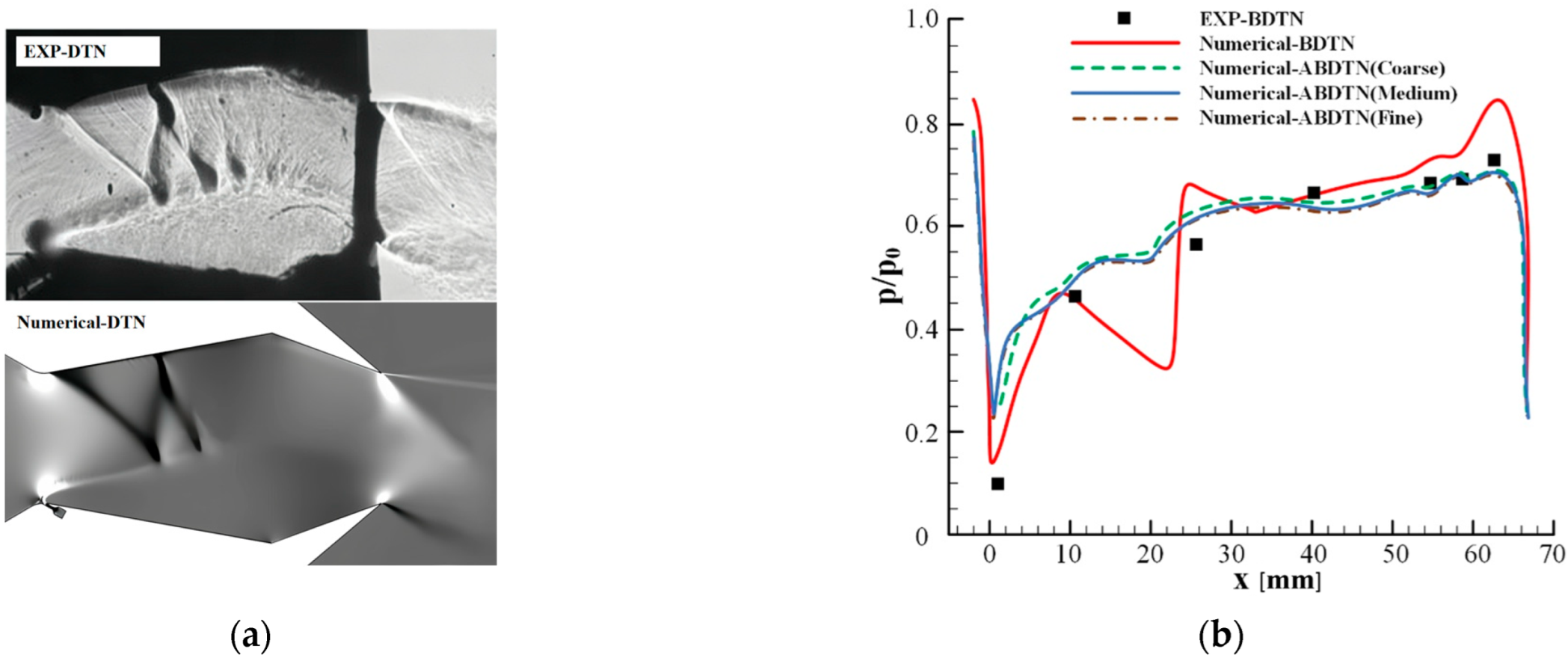
The computational data are compared with the experimental data [24,42] to validate the capability of the numerical method and the turbulence model. Due to the current research not yet obtaining clear schlieren images of the flow field for BDTNs or ABDTNs, the main focus is on comparing the flow field characteristics of the DTN model in [24]. Considering the lack of experimental studies on ABDTNs, the current study focuses on validating and examining grid independence for a 3D model of the BDTN. A 3D BDTN case with a thickness of 50 mm in the z-direction is set up for numerical simulations with an NPR of 10. The results are compared with experimental data from reference [42] to assess the accuracy of the turbulence model employed in this study for 3D numerical investigations on BDTNs. Furthermore, three grid sizes—fine, medium, and coarse—are employed in the ABDTN 3D model to verify grid independence, with total grid counts of approximately 650,000, 400,000, and 200,000, respectively. Considering that variations in the BDTN flow field predominantly occur near the lower wall, the analysis focuses on the pressure distribution on the lower wall. Starting from the axis at the upstream throat of the nozzle, the pressure distribution on the lower wall (intersection of the z = 0 plane and the cavity lower surface) for each case is shown in Figure 3. The horizontal and vertical coordinates are non-dimensionalized using the cavity length L0 between the upstream and downstream throats and the inlet pressure p0.
It is evident that the numerically predicted wave structures exhibit excellent agreement with the experimental flow visualization in Figure 3a. Figure 3b indicates that the simulation results closely match the experimental values too, suggesting that the turbulence model effectively captures the flow characteristics of the DTN and BDTN and can be extended for use in the 3D model of the ABDTN. The pressure differences on the lower wall obtained with the three grid counts are minimal, with the medium and fine grids showing almost no difference. Therefore, the medium grid is chosen to balance computational quality and efficiency. Although there are currently no experimental studies on the two-phase flow in BDTN, multiple experimental and numerical studies [27,61,62,63,64] have validated the applicability of particle trajectory models for the calculations of two-phase flows in nozzles. Thus, the turbulence model and the two-phase flow model used in this study are suitable for numerical research on ABDTN two-phase flow.

3. Definitions of Nozzle Performance Parameters

The most critical parameters for evaluating the TV performance of the ABDTNs are the TV angle (δ) and the thrust coefficient (Cf). As the nozzle is axisymmetric in the z = 0 plane, no vector effect exists in the yaw direction. The TV angle is expressed as follows:
δ = tan 1 F y / F x
where Fx and Fy denote the nozzle axial force (the X-component of force) and normal force (the Y-component), respectively. They can be calculated using Equations (3) and (4), outlined below:
F x = A ρ v x v x + ( P o u t P a ) d A
F y = A ρ v x v y d A
where Pout and Pa are the static pressure at the nozzle outlet and the back pressure, respectively.
The thrust coefficient is defined in Equation (5).
C f = F r / F i
where Fr and Fi are the resultant thrust and the ideal isentropic thrust, respectively. They are calculated as shown in Equations (6) and (7):
F r = F x 2 + F y 2 + F z 2
F i = m ˙ 2 γ γ 1 R T in * 1 N P R 1 γ γ
where Fz denotes the side force (the Z-component of force) obtained from the equation F z = A ρ v x v z d A , and m ˙ is the actual mass flow rate at the nozzle inlet.
As the ABDTN configuration does not require the introduction of an additional secondary flow, the discharge coefficient does not characterize the nozzle performance. With a fixed bypass channel width, the secondary flow remains constant as a percentage of the main flow. The vector efficiency can be correlated with the TV angle. Hence, the discharge coefficient and vector efficiency are not listed separately in this study.

4. Results and Discussion

The ABDTN features a long bypass channel with significant curvature, and the cavity undergoes substantial geometric changes, which may lead to particle deposition during geometric transitions under two-phase flow conditions. This phenomenon can impact the performance of SRMs. Studying the characteristics of particle motion and deposition inside the nozzle is crucial. This research analyzes the TV characteristics of ABDTNs, which hold significant importance for the engineering application of ABDTNs in missile systems.

4.1. Particle Trajectory and Internal Flow Field

Figure 4 provides streamlined plots of the flow field inside the BDTN under pure gas-phase conditions and trajectory plots of particles with different diameters under two-phase flow conditions. In the pure gas-phase scenario, the introduction of bypass secondary flow results in a deviation in the upstream throat of the nozzle, with the flow closely following the lower wall downstream and forming a recirculation region in the upper part of the cavity. Constrained by the geometry of the nozzle and the recirculation region, the outflow forms at a certain angle, generating vector thrust. In each case, the trajectories of particles with different diameters differ significantly. Small-diameter particles, being lighter and having lower inertia, are more affected by the drag force of the gas phase, making their influence more pronounced. Consequently, particle motion weakens as the diameter increases. At D = 5 μm, the trajectories closely align with the gas-phase streamlines in the pure gas-phase scenario, essentially occupying the entire mainstream flow channel. Particles only collide and decelerate with the wall at the bends of the bypass channel, the converging section, and the edge of the recirculation region. As D increases to 20 μm, particle motion gradually weakens, and trajectories gradually rise, converging toward the axis of the nozzle within the cavity. The particles start colliding with the wall in the bypass channel, upstream, and downstream converging sections, and they can hardly enter the upper recirculation region. Almost all particles flow out of the outlet section. At D = 40 μm, collisions between particles and the wall intensify, resulting in increasingly chaotic and dispersed trajectories within the cavity, spanning nearly the entire cross section at the outlet. Under the R–R distribution, where the D range is broader—mainly concentrated between 5 and 20 μm—the trajectories display characteristics similar to those of particles with varying diameters as previously described, indicating effective overall entrainment with the flow.
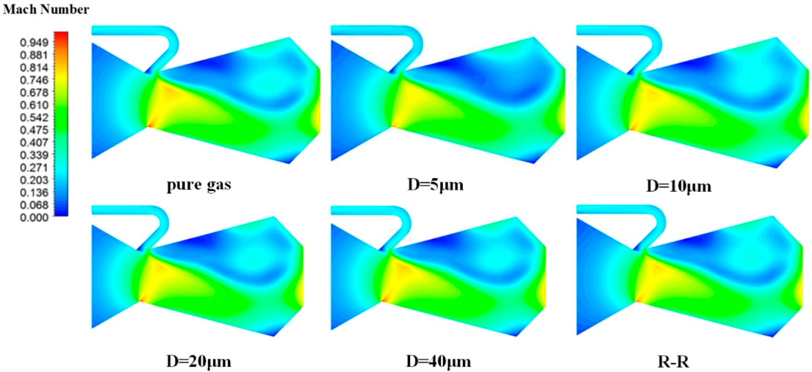
Figure 5 displays the Mach number distribution for the symmetric cross section of ABDTNs under pure gas-phase and two-phase flow conditions. The introduction of particles has almost no effect on the upstream converging section of the nozzle, while the Mach number slightly decreases in the flow channel area within the cavity. As the flow approaches the outlet section within the nozzle converging segment, the reduced confinement by the recirculation zone leads to an increase in the effective flowpath cross-sectional area. This counterintuitive expansion facilitates fluid decompression and acceleration, thereby elevating local flow velocity. The addition of 5-micrometer-diameter particles significantly reduces the intensity of the oblique shock at the upstream throat of the nozzle and reduces the Mach number in the upper recirculation region of the cavity. Larger-diameter particles display weaker entrainment with the flow and experience weaker drag forces from the gas phase, resulting in a smaller impact on the Mach number in the flow field. As the diameter increases to 40 μm, particle distribution within the cavity becomes more chaotic, leading to a more dispersed hindrance to the gas phase. The Mach number distribution in the flow field approaches a state close to the pure gas phase. Under the R–R distribution, the flow field inside the nozzle is similar to that observed for D = 20 μm particles. Additionally, owing to the constant mass fraction of particles in the gas phase, larger diameters result in fewer particles, limiting their interaction with the gas phase. Consequently, the Mach number distribution in the flow field becomes closer to that of the pure gas phase.

4.2. Particle Deposition Characteristics

Figure 6 and Figure 7, respectively, depict the distribution of particle concentrations along the nozzle axis and the symmetry plane for each case. As shown in Figure 6, the particle concentration along the axis is lower at D = 1–30 μm and under the R–R distribution, mainly because smaller-diameter particles exhibit better entrainment with the flow and are present at a lower concentration along the nozzle axis. At D > 30 μm, particles collide and reflect off the wall of the upstream converging section and, thus, move closer to the nozzle axis. The probability of particles crossing the axis increases after they pass through the upstream throat. However, owing to the lesser influence of gas-phase drag on larger-diameter particles, the collision and reflection of particles with the wall intensify. Moreover, the presence of shockwaves near the upstream throat results in a more uneven particle concentration distribution in this region, exhibiting sawtooth-like oscillations.
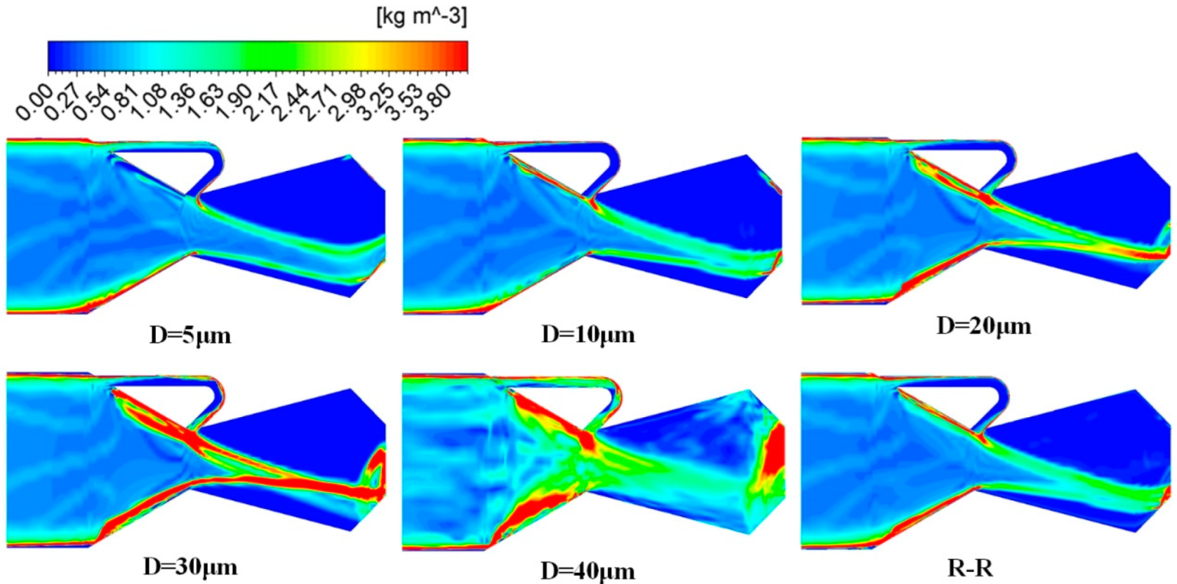
As depicted in Figure 7, a higher particle concentration occurs near the wall after mesh refinement as particles are released from the midpoint of the grid edges. Furthermore, as the upstream converging section narrows, the particle concentration significantly increases. At D = 5 and 10 μm, no extensive high-particle-concentration region occurs on the symmetry plane. However, with increasing D, particles gradually converge toward the axis, forming a horizontal “λ”-shaped high-particle-concentration zone inside the nozzle. At D = 40 μm, after particles collide with the wall in the upstream converging section, they reflect toward the axis, causing the high-particle-concentration region in the converging section to extend toward the centerline, with a relatively dispersed distribution within the cavity. Owing to geometric convergence at the nozzle exit, particle concentration increases. Most particles collide with the lower wall and escape through the exit section, and the escape locations near the upper part of the exit section form a high-particle-concentration zone. The shape of the particle-concentration zone under the R–R distribution is closest to that of the D = 20 μm case. However, owing to the strong entrainment of small-diameter particles and the greater inertia of large-diameter particles, some dispersion in particle aggregation occurs within the cavity. The high-particle-concentration zone in the bypass channel mainly distributes in the near-wall regions of the outer contour. Collisions and rebounds between large-diameter particles and the channel wall thicken the high-concentration region.
Figure 8 presents deposition maps on the wall for five cases with significant differences. Particle deposition primarily occurs at the outer edges of the bends in the bypass channel and in the upstream and downstream converging sections of the nozzle. At D = 5 μm, particles exhibit good entrainment with the flow, and significant deposition mainly occurs at the outer edges of the bends in the bypass channel and the converging section of the cavity (Figure 4), attributable to collisions and the deceleration of particles with the wall. As D increases, some particles collide with the wall of the upstream converging section, increasing the deposition rate at that location. Within the cavity, particles gradually rise toward the centerline. Closer to the exit, particles collide with the lower wall, leading to particle deposition. According to Figure 4 and Figure 7, at D = 40 μm, particles can reach almost all areas of the nozzle owing to repeated collisions and changes in direction. This leads to particle deposition in most locations of the nozzle wall. However, the deposition is primarily concentrated at the outer edges of the bends in the bypass channel and the lower wall of the converging section within the cavity. Under the R–R distribution, the wall deposition pattern combines the characteristics of particle deposition from different cases. Additionally, a particle deposition ring is formed on the cavity wall. According to Figure 4, this phenomenon is a result of collisions between small-diameter particles and the wall at the edge of the recirculation region alongside wall deposition from large-diameter particles.

4.3. TV Performance

Figure 9 illustrates the TV performance of the BDTN under the pure gas phase (D = 0 μm) and different particle sizes. The introduction of the particle phase reduces the axial and normal thrusts of the nozzle, thereby affecting the TV angle and the thrust coefficient. As D increases, the axial thrust and the thrust coefficient gradually recover and tend toward the pure gas-phase condition. The normal force and TV angle initially decrease and then increase and eventually decrease again, approaching a stable state. At D = 20 μm, the nozzle achieves the maximum TV angle of 11.12°, with a thrust coefficient of 0.822. Under the R–R distribution, the TV angle is 10.37° and the thrust coefficient is 0.815. The vector angle and thrust coefficient are 1.5° and 0.039 lower than those under the pure gas phase, respectively.
The main reason behind these trends is that smaller-diameter particles exhibit better entrainment with the flow, and the hindering effect of drag forces between the two phases occurs in both the axial and normal directions. As D increases, the drag forces between the two phases decrease, allowing the axial force and the thrust coefficient to gradually recover. However, the normal force is influenced by factors such as the entrainment of particles with the flow and collisions with the wall, resulting in non-monotonic changes. As D increases to 20 μm, the trajectories of the particle phase rise and become highly concentrated. Following collision and reflection in the converging section of the cavity, the particle phase exhibits a higher escape angle than the gas-phase exit angle. This results in an increase in the thrust increment caused by the particle phase, with the normal projection surpassing the axial projection, thereby leading to a significant increase in the TV angle. As D continues to increase, the influence of drag forces between the two phases becomes limited. Additionally, the increase in D leads to a decrease in the particle quantity at a constant mass fraction, and the effects of particle velocity and temperature lag become less pronounced. This causes the axial thrust and thrust coefficient of the nozzle to gradually recover. Meanwhile, the normal thrust decreases, resulting in a reduction in the TV angle. The parameters of the nozzle TV performance under the R–R distribution closely resemble those at D = 20 μm, aligning with the previous analysis.

5. Conclusions

Numerical simulations of three-dimensional two-phase flows in an ABTDN were performed under various particle-size conditions. Particle trajectories, internal flow characteristics, particle deposition characteristics, and TV performance were investigated. The following conclusion can be drawn:
(1)
Particle trajectories differ significantly with D within the nozzle. As D increases, the entrainment of particles with the flow weakens. Submicron- to submillimeter-sized particles (D = 1–10 μm) exhibit trajectories that closely aligned with the streamlines in the pure gas-phase case, with minimal collisions with the nozzle walls. As D increases, particle trajectories gradually approach the axis, the distribution area within the cavity narrows, and the particle concentration significantly increases. This results in the formation of a horizontal λ-shaped high-particle-concentration zone within the nozzle. At D = 40 μm, particle distribution within the cavity becomes more dispersed owing to wall collisions and inertial effects;
(2)
The continuous deposition of high-temperature condensate particles on the walls can lead to severe issues such as wall erosion and flow passage blockage. The significant deposition of particles within the bypass channel can substantially reduce the bypass jet flow rate during engine operation, thereby increasing the instability of the TV performance. Moreover, this deposition poses a significant risk of erosion. In the design and manufacturing of the nozzle, it is crucial to prioritize thermal protection at the bends of the bypass channel, the upstream converging section of the nozzle, and the converging section of the cavity. Additionally, efforts should be made to improve the efficiency of solid propellant combustion and reduce the mass fraction of condensate particles in the combustion gases;
(3)
The introduction of the particle phase reduces the axial thrust and TV angles of the nozzle. Changes in D directly affect the axial and normal forces of the nozzle, thereby influencing TV angles and thrust coefficients. At NPR = 200 and an inlet total temperature of 3000 K, the D = 20 μm scenario yields the maximum TV performance: a TV angle of 11.12° and a thrust coefficient of 0.822. Under the R–R distribution, the TV angle is 10.37° and the thrust coefficient is 0.815;
(4)
Under the R–R distribution, particles with a diameter of 20 μm account for the highest mass fraction, and the TV performance parameters are consistent with those of the case with a uniform D of 20 μm. However, the internal flow characteristics and particle deposition characteristics encompass the features observed across various particle-size conditions.
In summary, the numerical study of an ABDTN in this paper can reflect the flow field characteristics, particle deposition characteristics, and TV characteristics well under the condition of two-phase flow, which provide important references for the design of SRMs with ABDTNs. In the future, more experimental studies are needed to further verify and research the relevant characteristics. Additionally, the dynamic adjustment and control of the vector thrust need to be further studied to better apply ABDTNs to engineering practice.

Author Contributions

Conceptualization, X.X. and H.Q.; methodology, software, and validation, Z.S. and X.X.; formal analysis, Y.Z. (Yujie Zhu) and Y.H.; investigation, Y.Z. (Yin Zhang); resources, supervision, project administration, and funding acquisition, Z.S. and Y.H. All authors have read and agreed to the published version of the manuscript.

Funding

This research was funded by the National Natural Science Foundation of China (Grant Nos. 91952110, 12302383, 92152201, and 52375559), and the National Natural Science Foundation of Shaanxi Province (Grant No. 2023-JC-QN-0052).

Data Availability Statement

The data presented in this study are available in the article.

Conflicts of Interest

The authors declare no conflicts of interest.

References

  1. Wilde, P.I.A.; Crowther, W.J.; Buonanno, A.; Savvaris, A. Aircraft Control Using Fluidic Maneuver Effectors. In Proceedings of the 26th AIAA Applied Aerodynamics Conference, Honolulu, HI, USA, 18–21 August 2008. [Google Scholar]
  2. Xia, X.; Gao, F.; Huang, G.; Yang, W. Research progress of the dual throat thrust-vectoring nozzle. Adv. Aeronaut. Sci. Eng. 2017, 8, 249–255, 298. [Google Scholar] [CrossRef]
  3. Cong, R.; Ye, Y.; Zhao, Z.; Wu, J. Numerical research on jet tab thrust vector nozzle aerodynamic characteristics. Acta Aerodyn. Sin. 2019, 1300, 012089. [Google Scholar] [CrossRef]
  4. Forghany, F. Numerical investigation of injection angle effects on shock vector control performance. Proc. Inst. Mech. Eng. Part G J. Aerosp. Eng. 2019, 233, 405–417. [Google Scholar] [CrossRef]
  5. Jingwei, S.; Zhanxue, W.; Li, Z.; Xiaolin, S. Investigation on Flow Characteristics of SVC Nozzles. J. Appl. Fluid Mech. 2018, 11, 331–342. [Google Scholar] [CrossRef]
  6. Islam, M.S.; Hasan, M.A.; Hasan, A.B.M.T. An analysis of thrust vectoring in a supersonic nozzle using bypass mass injection. AIP Conf. Proc. 2018, 1980, 040014. [Google Scholar] [CrossRef]
  7. Salimi, M.R.; Askari, R.; Hasani, M. Computational Investigation of Effects of Side-Injection Geometry on Thrust-Vectoring Performance in a Fuel-Injected Dual Throat Nozzle. J. Appl. Fluid Mech. 2022, 15, 1137–1153. [Google Scholar] [CrossRef]
  8. Nafi, M.A.; Hasan, A.B. 3D Computational Study of Thrust Vectoring using Bypass Mass Injection in a Propulsion Nozzle. In AlP Conference Proceedings, Proceedings of the 8th Bsme International Conference on Thermal Engineering, Dhaka, Bangladesh, 19–21 December 2018; AIP Publishing: Melville, NY, USA, 2019; Volume 2121, p. 050013. [Google Scholar] [CrossRef]
  9. Ferlauto, M.; Marsilio, R. Computational Investigation of Injection Effects on Shock Vector Control Performance. In Proceedings of the 2018 Joint Propulsion Conference, Cincinnati, OH, USA, 9–11 July 2018. [Google Scholar]
  10. Zong, H.; Chiatto, M.; Kotsonis, M.; de Luca, L. Plasma Synthetic Jet Actuators for Active Flow Control. Actuators 2018, 7, 77. [Google Scholar] [CrossRef]
  11. AlAsadi, A.A.-M.H.; Faseeh, A.H. Fluidics Jet Vectoring for Incompressible Flow by Using Counter Flow Method for Circular Duct. Alnahrain J. Eng. Sci. 2017, 20, 911–923. [Google Scholar]
  12. Wu, K.; Zhang, G.; Kim, T.H.; Kim, H.D. Numerical parametric study on three-dimensional rectangular counter-flow thrust vectoring control. Proc. Inst. Mech. Eng. Part G J. Aerosp. Eng. 2020, 234, 2221–2247. [Google Scholar] [CrossRef]
  13. Wu, K.; Kim, H.; Jin, Y. Fluidic thrust vector control based on counter-flow concept. Proc. Inst. Mech. Eng. Part G J. Aerosp. Eng. 2019, 233, 1412–1422. [Google Scholar] [CrossRef]
  14. Li, J.; Lu, W.; Wang, Y.; Zhang, Y. Improved design and performance analysis of counterflow thrust vectoring technology under high subsonic. J. Intell. Fuzzy Syst. 2018, 34, 1213–1223. [Google Scholar] [CrossRef]
  15. Saghafi, F.; Banazadeh, A. Co-flow fluidic thrust vectoring requirements for longitudinal and lateral trim purposes. In Proceedings of the 42nd AIAA/ASME/SAE/ASEE Joint Propulsion Conference & Exhibit, Sacramento, CA, USA, 9–12 July 2006. [Google Scholar]
  16. Al-Asady, A.A.A.; Abdullah, A.M. Fluidics Thrust Vectoring Using Co-Flow Method. Al-Nahrain J. Eng. Sci. 2017, 20, 5–18. [Google Scholar]
  17. Miller, D.; Yagle, P.; Hamstra, J. Fluidic throat skewing for thrust vectoring in fixed-geometry nozzles. In Proceedings of the 37th Aerospace Sciences Meeting and Exhibit, Reno, NV, USA, 11–14 January 1999. [Google Scholar]
  18. Williams, R.; Vittal, B. Fluidic Thrust Vectoring and Throat Control Exhaust Nozzle. In Proceedings of the 38th AIAA/ASME/SAE/ASEE Joint Propulsion Conference & Exhibit, Indianapolis, IN, USA, 7–10 July 2002. [Google Scholar]
  19. Yagle, P.J.; Miller, D.N.; Ginn, K.B.; Hamstra, J.W. Demonstration of Fluidic Throat Skewing for Thrust Vectoring in Structurally Fixed Nozzles. J. Eng. Gas Turbines Power 2001, 123, 502–507. [Google Scholar] [CrossRef]
  20. Ali, A.; Rodriguez, C.; Neely, A.; Young, J. Combination of Fluidic Thrust Modulation and Vectoring in a 2D Nozzle; University of New South Wales Canberra: Canberra, Australia, 2012. [Google Scholar]
  21. Deere, K. Summary of Fluidic Thrust Vectoring Research at NASA Langley Research Center. In Proceedings of the 21st AIAA Applied Aerodynamics Conference, Orlando, FL, USA, 23–26 June 2003. [Google Scholar]
  22. Deere, K.; Berrier, B.; Flamm, J.; Johnson, S. Computational Study of Fluidic Thrust Vectoring Using Separation Control in a Nozzle; NASA Langley Research Center: Hampton, VA, USA, 2003. [Google Scholar]
  23. Flamm, J.D.; Deere, K.A.; Mason, M.L.; Berrier, B.L.; Johnson, S.K. Design Enhancements of the Two-Dimensional, Dual Throat Fluidic ThrustVectoring Nozzle Concept. In Proceedings of the 3rd AIAA Flow Control Conference, San Francisco, CA, USA, 5–8 June 2006. [Google Scholar]
  24. Deere, K.A.; Flamm, J.D.; Berrier, B.L.; Johnson, S.K. Computational Study of an Axisymmetric Dual Throat Fluidic Thrust Vectoring Nozzle for a Supersonic Aircraft Application. In Proceedings of the 43rd AIAA/ASME/SAE/ASEE Joint Propulsion Conference & Exhibit, Cincinnati, OH, USA, 8–11 July 2007; NASA Langley Research Center: Hampton, VA, USA, 2007. [Google Scholar]
  25. Flamm, J.D.; Deere, K.A.; Mason, M.L.; Berrier, B.L.; Johnson, S.K. Experimental Study of an Axisymmetric Dual Throat Fluidic Thrust Vectoring Nozzle for Supersonic Aircraft Application. In Proceedings of the 43rd AIAA/ASME/SAE/ASEE Joint Propulsion Conference & Exhibit, Cincinnati, OH, USA, 8–11 July 2007; NASA Langley Research Center: Hampton, VA, USA, 2007. [Google Scholar]
  26. Flamm, J.D.; Deere, K.A.; Berrier, B.L.; Johnson, S.K.; Mason, M.L. Experimental Study of a Dual-Throat Fluidic Thrust-Vectoring NozzleConcept. In Proceedings of the 41st AIAA/ASME/SAE/ASEE Joint Propulsion Conference & Exhibit, Tucson, AZ, USA, 10–13 July 2005. [Google Scholar]
  27. Deere, K.A.; Berrier, B.L.; Flamm, J.D.; Johnson, S.K. A Computational Study of a New Dual Throat Fluidic Thrust Vectoring Nozzle Concept. In Proceedings of the 41st AIAA/ASME/SAE/ASEE Joint Propulsion Conference & Exhibit, Tucson, AZ, USA, 10–13 July 2005. [Google Scholar]
  28. Shin, C.S.; Kim, H.D.; Setoguchi, T.; Matsuo, S. A computational study of thrust vectoring control using dual throat nozzle. J. Therm. Sci. 2010, 19, 486–490. [Google Scholar] [CrossRef]
  29. Wu, K.X.; Kim, T.H.; Kim, H.D. Numerical Study of Fluidic Thrust Vector Control Using Dual Throat Nozzle. J. Appl. Fluid Mech. 2021, 14, 73–87. [Google Scholar] [CrossRef]
  30. Ferlauto, M.; Marsilio, R. Numerical Investigation of the Dynamic Characteristics of a Dual-Throat-Nozzle for Fluidic Thrust-Vectoring. AIAA J. 2017, 55, 86–98. [Google Scholar] [CrossRef]
  31. Ferlauto, M.; Marsilio, R. Numerical Simulation of Fluidic Thrust-Vectoring. Aerotec. Missili Spaz. 2016, 95, 153–162. [Google Scholar] [CrossRef]
  32. Wang, Y.; Xu, J.; Huang, S. Study of Starting Problem of Axisymmetric Divergent Dual Throat Nozzle. J. Eng. Gas Turbines Power 2017, 139, 062602. [Google Scholar] [CrossRef]
  33. Wu, K.; Kim, H.D. Study on Fluidic Thrust Vector Control Based on Dual-Throat Concept. J. Korean Soc. Propuls. Eng. 2019, 23, 24–32. [Google Scholar] [CrossRef]
  34. Wang, Y.-S.; Xu, J.-L.; Huang, S.; Lin, Y.-C.; Jiang, J.-J. Experimental and numerical investigation of an axisymmetric divergent dual throat nozzle. Proc. Inst. Mech. Eng. Part G J. Aerosp. Eng. 2020, 234, 563–572. [Google Scholar] [CrossRef]
  35. Maruyama, Y.; Sakata, M.; Takahashi, Y. Performance Analyses of Fluidic Thrust Vector Control System Using Dual Throat Nozzle. AIAA J. 2022, 60, 1730–1744. [Google Scholar] [CrossRef]
  36. Li, S.; Sun, Z.; Zha, B.; Zhu, Y.; Ding, Y.; Xia, Y. A family of spatio-temporal optimized finite difference schemes with adaptive dispersion and critical-adaptive dissipation for compressible flows. J. Comput. Phys. 2023, 474, 111821. [Google Scholar] [CrossRef]
  37. Wu, K.; Kim, T.H.; Kim, H.D. Visualization and analysis on the thrust vectoring control in three-dimensional dual-throat nozzles. J. Vis. 2021, 24, 891–915. [Google Scholar] [CrossRef]
  38. Fan, Z.; Xu, J.; Wang, Y. Effects of downstream throat on aerodynamic performance of dual throat nozzle. J. Aerosp. Power 2015, 30, 580–587. [Google Scholar] [CrossRef]
  39. He, J.; Chen, Q.; Dong, J. Numerical investigation of aerodynamic performance on dual throat thrust vectoring nozzle. J. Nanjing Univ. Aeronaut. Astronaut. 2017, 49, 16–23. [Google Scholar]
  40. Li, Y.; Li, J.; Yang, D.; Zhang, Y.; Zhou, Q. Numerical study of a dual-throat fluidic thrust-vectoring nozzle. Acta Aerodyn. Sin. 2015, 33, 211–217. [Google Scholar] [CrossRef]
  41. Li, M.; Xu, J.L.; Huang, S.G.; Gu, R.; Liao, H.L.; Fu, Y.; Mo, J.W.; Yu, Y. Bypass Type Double-Throat Passive Vectoring Sprayer Nozzle. CN2011103842883, 2011. Available online: http://epub.cnipa.gov.cn/Dxb/IndexQuery (accessed on 31 December 2024).
  42. Gu, R.; Xu, J.; Guo, S. Experimental and numerical investigations of a bypass dual throat nozzle. J. Eng. Gas Turbines Power 2014, 136, 084501. [Google Scholar] [CrossRef]
  43. Gu, R.; Xu, J. Dynamic Experimental Investigations of a Bypass Dual Throat Nozzle. J. Eng. Gas Turbines Power 2015, 137, 084501. [Google Scholar] [CrossRef]
  44. Hamedi-Estakhrsar, M.H.; Mahdavy-Moghaddam, H. Experimental evaluation and numerical simulation of performance of the bypass dual throat nozzle. Proc. Inst. Mech. Eng. Part G J. Aerosp. Eng. 2021, 235, 768–781. [Google Scholar] [CrossRef]
  45. Hamedi-Estakhrsar, M.; Ferlauto, M.; Mahdavy-Moghaddam, H. Numerical study of secondary mass flow modulation in a Bypass Dual-Throat Nozzle. Proc. Inst. Mech. Eng. Part G J. Aerosp. Eng. 2020, 235, 488–500. [Google Scholar] [CrossRef]
  46. Afridi, S.; Khan, T.A.; Shah, S.I.A.; Shams, T.A.; Mehmood, K.; Li, W.; Kukulka, D. Numerical Investigation on the Thrust Vectoring Performance of Bypass Dual Throat Nozzle. Energies 2023, 16, 594. [Google Scholar] [CrossRef]
  47. Afridi, S.; Khan, T.A.; Shah, S.I.A.; Shams, T.A.; Mohiuddin, K.; Kukulka, D.J. Techniques of Fluidic Thrust Vectoring in Jet Engine Nozzles: A Review. Energies 2023, 16, 5721. [Google Scholar] [CrossRef]
  48. Afridi, S.; Khan, T.A. Multi-objective nozzle design optimization for maximum thrust vectoring performance. Proc. Inst. Mech. Eng. Part G J. Aerosp. Eng. 2023, 237, 587–599. [Google Scholar] [CrossRef]
  49. Wang, Y.; Xu, J.; Huang, S.; Lin, Y.; Jiang, J. Computational study of axisymmetric divergent bypass dual throat nozzle. Aerosp. Sci. Technol. 2019, 86, 177–190. [Google Scholar] [CrossRef]
  50. Wang, Y.; Xu, J.; Huang, S.; Jiang, J.; Pan, R. Design and Preliminary Analysis of the Variable Axisymmetric Divergent Bypass Dual Throat Nozzle. J. Fluids Eng. 2020, 142, 061204. [Google Scholar] [CrossRef]
  51. Lin, Y.; Xu, J.; Han, J.; Huang, S.; Wang, Y. Flight test of a fluidic thrust vectoring flying wing without rudder. J. Aerosp. Power 2019, 34, 701–707. [Google Scholar] [CrossRef]
  52. Jiang, J.; Xu, J.; Huang, S.; Wang, Y.; Pan, R. Numerical study of bypass dual throat nozzle with parallelogram cross-section. J. Aerosp. Power 2020, 35, 805–814. [Google Scholar] [CrossRef]
  53. Jiang, J. Research on Bzypass Dual Throat Nozzle with Parallelogram Cross-Section and the Transition Section; Nanjing University of Aeronautics and Astronautics: Nanjing, China, 2020. [Google Scholar]
  54. Xia, X.; Gao, F.; Zhang, Q. Investigation on the vector performance of a bypass dual throat nozzle with injection at the divergent section. Acta Aerodyn. Sin. 2021, 39, 51–58. [Google Scholar] [CrossRef]
  55. Wu, K.; Kim, H. A fluidic thrust vector control using the bypass flow in a dual throat nozzle. J. Mech. Sci. Technol. 2021, 35, 3435–3443. [Google Scholar] [CrossRef]
  56. Huang, S.; Xu, J.; Yu, K.; Wang, Y.; Pan, R. Design and experimental study of a bypass dual throat nozzle with the ability of short/vertical takeoff and landing. Aerosp. Sci. Technol. 2022, 121, 107301. [Google Scholar] [CrossRef]
  57. Huang, S.; Xu, J.; Yu, K.; Wang, Y.; Pan, R.; Chen, K.; Zhang, Y. Numerical study of a trapezoidal bypass dual throat nozzle. Chin. J. Aeronaut. 2023, 36, 42–62. [Google Scholar] [CrossRef]
  58. Zhang, Y.; Xu, J.; Pan, R.; Li, Y.; Ma, Z.; Huang, S. Numerical investigation of short takeoff and landing exhaust system using bypass dual throat nozzle. Aerosp. Sci. Technol. 2023, 138, 108316. [Google Scholar] [CrossRef]
  59. Xia, X.; Sun, Z.; Hu, Y.; Qu, H.; Li, S.; Zhang, Y.; Liu, J. Numerical Investigation on Aerodynamic Vector Performance of a Axisymmetric Bypass Dual Throat Nozzle. In Proceedings of the 6th China Aeronautical Science and Technology Conference, Wuzhen, China, 26–28 September 2023; Available online: https://xcx.csaa.org.cn/client/index.html (accessed on 31 December 2024).
  60. Brainard, A.J. Gas Tables: International Version Second Edition (SI Units); Keenan, J.H., Chao, J., Kaye, J., Eds.; Chemical Engineering Department, University of Pittsburgh: Pittsburgh, PA, USA; John Wiley and Sons: New York, NY, USA, 1984; Volume 30, p. 172. [Google Scholar] [CrossRef]
  61. Huang, H.; Feng, Z.; Ma, L.; Yang, T.; Li, G. Effects of Particle Parameters on Performance of Axisymmetric Supersonic Gas-Solid Two-Phase Flow Nozzle. J. Propuls. Technol. 2023, 44. [Google Scholar] [CrossRef]
  62. Zhang, G.; Fan, Y.; Yang, R.; Li, S. Application of the Rosin-Rammler function to describe quartz sandstone particle size distribution produced by high-pressure gas rapid unloading at different infiltration pressure. Powder Technol. 2022, 412, 117982. [Google Scholar] [CrossRef]
  63. Li, Z.; Xiang, H.; Zhang, X. Numerical simulation of composite solid propellant rocket motor exhaust plume. J. Solid Rocket Technol. 2014, 37, 37–42. [Google Scholar]
  64. Hao, X.; Yan, Y.; Cao, T.; Li, W.; Zhang, H. Numerical prediction of the two-phase flow and radiation effects on the thermal environment and ablation of solid rocket nozzle. Int. J. Therm. Sci. 2024, 197, 108794. [Google Scholar] [CrossRef]
Figure 1. The configuration of an axisymmetric BDTN model: (a) geometrical parameters; (b) axially symmetrical construction.
Aerospace 12 00226 g001
Figure 2. Mesh for the simulation domain.
Aerospace 12 00226 g002
Figure 3. Model validation—comparison of numerical schlieren and experimental shadowgraph [24] (a) and comparison of pressure distributions on the lower wall for experimental case [42] and numerical cases (b).
Aerospace 12 00226 g003
Figure 4. Streamlines under pure gas-phase conditions and trajectory of particles with different diameters.
Aerospace 12 00226 g004
Figure 5. Mach number distribution at the symmetric cross section.
Aerospace 12 00226 g005
Figure 6. Distribution of particle concentration along the nozzle axis.
Aerospace 12 00226 g006
Figure 7. Particle concentration distribution map in the symmetric plane.
Aerospace 12 00226 g007
Figure 8. Particle deposition near the wall.
Aerospace 12 00226 g008
Figure 9. Thrust performance (a) and TV performance (b) for different cases.
Aerospace 12 00226 g009
Table 1. Particle diameters under the R–R distribution.
Diameter (μm)Mass Fraction (%)
15
515
1025
2040
4010
805
Disclaimer/Publisher’s Note: The statements, opinions and data contained in all publications are solely those of the individual author(s) and contributor(s) and not of MDPI and/or the editor(s). MDPI and/or the editor(s) disclaim responsibility for any injury to people or property resulting from any ideas, methods, instructions or products referred to in the content.