Review

Aerodynamics of Corrugated Wings: Past, Present, and Future

School of Engineering and Built Environment, Sheffield Hallam University, Sheffield S1 1WB, UK
*
Author to whom correspondence should be addressed.
Aerospace 2025, 12(3), 262; https://doi.org/10.3390/aerospace12030262
Submission received: 10 January 2025 / Revised: 21 February 2025 / Accepted: 12 March 2025 / Published: 19 March 2025
(This article belongs to the Section Aeronautics)

Abstract

:
This paper provides a detailed review of the evolution and development of corrugated wings, a biomimetic concept that is very effective under low Reynolds number flights. We will highlight, through reviewing experimental and numerical studies, the emphasis on its aerodynamic performance for lift enhancement, flow separation delay, and drag reduction in the aerodynamics of corrugated wings. Furthermore, we focus on topics such as fluid–structure interaction and aeroacoustics, presenting the possibility of morphing wing technologies in tandem and its effects on an angle of attack at various flight modes. This review outlines durability issues, materials selection, and experimental testing complemented by numerical models while determining the importance of interdisciplinary developments within corrugated wing aerodynamics using potential AI-assisted design. Our review envisions the application of aerodynamics of corrugated wings in the development of UAVs, MAVs, and future advanced aviation systems by integrating the principles from biology to engineering.

1. Introduction

Corrugated wings are an emerging area of interest in biometric aircraft design and aerodynamics studies. This interest stems from the potential aerodynamic advantages of corrugated wing structures over traditional aerofoils in low Reynolds number flight regimes [1,2,3,4]. Corrugated wings have been shown to enable flight at greater angles of attack compared to conventional wing designs. These advantages are being explored to enhance the performance of modern aircraft, particularly in vehicles such as UAVs and MAVs. Moreover, some studies have reported a significant performance improvement due to corrugation, especially at high angles of attack [5,6].
This review paper, therefore, aims to critically analyze the current understanding of corrugated wing aerodynamics to assess its viability as a future replacement for traditional aerofoils. This will include identifying the advantages of corrugation in aerodynamic performance, such as the ability to delay the onset of flow separation and enhance lift through vortical manipulation. Disadvantages, current limitations, and gaps in research will also be explored to facilitate further research and development needed to understand the complex interaction between corrugation and aerodynamic performance. Moreover, the review will aim to trace the historical development of corrugated aerodynamics, from its initial identification to the current stage of understanding.
Corrugated wings are characterized by alternating elevated ridges that form recessed valleys along the chord length. These wings also typically vary in shape along the spanwise length of the wing. This unique wing profile can be observed in many instances in nature, most notably in insects. The following section will highlight these instances and explore why corrugation has been identified as an area of research interest.

1.1. Corrugated Wing Flight

1.1.1. Corrugation in Nature

One of the most studied examples of corrugated wings found in nature is the dragonfly (Anisoptera) wing. However, the unique wing design can also be found in various insects including beetles (Coleoptera) and ladybirds (Coccinellidae). The reason for the heavy focus on the corrugation found on the dragonfly wing is due to its diverse range of flight capabilities. This includes the ability to hover, perform backwards flight, and quickly accelerate their flight. Their wing design grants them exceptional agility and speed, making them the quickest and most maneuverable flyers in the insect kingdom [7]. The dragonfly can glide up to 30 s without any significant loss of altitude [8]. The insect is classified as a low Reynolds number flier, with a usual flight Reynolds being in the range of 102–105 [9].
Although being less studied, as mentioned above, many types of beetles also exhibit corrugated wing profiles. The corrugations found in beetle flight have been identified to prevent large-scale flow separation [10]. Beetles typically operate at a lower Reynolds number range compared to the dragonfly, operating at a Reynolds range of 102.
Since both dragonflies and beetles possess corrugated wings and operate at low Reynolds numbers, it suggests that this evolutionary adaptation is particularly beneficial for low-speed flight. Micro-CT scanning reveals that from an aerodynamic perspective, dragonfly wings’ stiffness and precise aeroelastic design enable superior energy efficiency, load management, and optimized flight performance compared to flexible MAV wings. As shown in Figure 1, the digital reconstruction and cross-sectional micro-CT images of the hindwing of Sympetrum vulgatum highlight the corrugated wing architecture, built up by the intricate arrangement of veins and membranes [11]. This detailed structural analysis demonstrates how the vein and membrane thickness increases from the wingtip to the root, allowing the wing to effectively bear both inertial and aerodynamic loads. This insight can be applied to identify potential applications for this technology, such as in low-speed surveillance Unmanned Aerial Vehicles (UAVs).

1.1.2. History of Corrugated Wing Research Leading to Technical Advances

The study of corrugated aerodynamics has been an area of research for centuries. However, fascination with dragonfly flight dates back even further. Leonardo da Vinci (1452–1519) observed the remarkable flight capabilities of dragonflies and inspired by their four-winged morphology, conceptualized the ‘mechanical butterfly’—an early unmanned aerial design that sought to mimic insect flight dynamics. Early research includes work by [12], which notes the early interest in the influence of corrugation on air flow patterns and suggests the potential benefit aerodynamically. Early attempts to understand the aerodynamics of corrugated surfaces relied on wind tunnel experiments and observing movements in fluids. While these studies confirmed the influence of corrugations on drag, they lacked the technological capability to analyze the complex aerodynamic derivatives required to predict performance accurately [13,14]. Advancements in technology introduced new methods of analysis which would allow for the individual flight mechanisms to be understood in detail. Such methods include the developments within computational fluid dynamics (CFD) [15] and experimentation using particle image velocimetry (PIV) [16]. These methods allowed for a more focused investigation into previously unknown phenomena such as vortical formation on the wing. Furthermore, these advancements in research methods enabled researchers to easily modify factors such as flight speed and corrugation geometry. The broader analysis provides a much deeper understanding of performance across various flight regimes and scenarios, which is important to build an overall profile of where the technology could be advantageous to implement in current technology. Through time, many research papers have also drawn the conclusion that the flight advantages observed in corrugated wings are applicable to the wings of bio-inspired flapping wing micro air vehicles (MAVs) [17,18,19].
From Figure 2, the evolution in technological advances effect on MAV design can be seen. The advancements have allowed for complex recreation and utilization of corrugated aerodynamics to bio-inspire future MAV and UAV designs.

1.1.3. Evolutionary Traits

Corrugation, a reoccurring feature across a variety of insect wings, has developed through millions of years of evolution. This suggests a clear evolutionary advantage for the insects. Insects exhibiting corrugated wings are provided with a unique evolutionary advantage. As mentioned above, the natural high maneuverability allows for precise control and movement during flight. This grants the insects the ability to navigate complex environments and hunt pray with greater agility. Moreover, the corrugated wing also provides a superior strength-to-weight ratio [24]. For low-mass insects, this is crucial, as minimizing weight is essential for improving flight efficiency. This evolutionary trait enables long-range flight with lower energy expenditure.
Furthermore, the unique profile of the dragonfly wing is not just in its shape; its geometry also varies along the length of the wing (longitudinal span), shown in Figure 3. As you move towards the tip, the corrugated profile flattens out, more closely resembling a flat plate. This evolutionary adaptation may enable passive flow control, allowing for variations in lift along the span, similar to a manufactured wing with engineered wing twist. This naturally optimized design reduces the need for additional energy expenditure to maintain stable and controlled flight.
Beyond its distinctive corrugated wings, the dragonfly possesses another unique feature: a four-wing tandem configuration arranged in two pairs. This evolutionary trait allows for enhanced maneuverability due to the independent movement of each wing allowing for an increase in flight control. The aerodynamic benefits of a corrugated tandem configuration will be explored in a subsequent section.
Overall, corrugated wings provide remarkable evolutionary advantages by enhancing flight performance in keyways. The adaptations are the reason dragonflies have been researched heavily and potentially provide a revolutionary bio-inspired solution to low flight with high maneuverability.

1.1.4. Aerodynamic Design and Application

There are various factors involved in the design process of corrugated wing studies. This varies from the shape, placement, and material of the wing. With these factors significantly impacting aerodynamic performance, research utilizing methods such as wind tunnel testing must be carefully analyzed to identify their design choices. As stated above, corrugated wings have been identified to have applications in UAV (unmanned ariel vehicle) and MAV (micro ariel vehicle) bio-inspired design. The use of these technologies plays an ever-growing role in supporting human activities in multidisciplinary fields including emergency aid, environmental monitoring, and 3D mapping [25]. Within these applications, significant 3D geographical mapping and stable flight at low speeds for extended periods are essential in producing consistent and accurate imaging.
However, traditional aerofoils are not ideal for low Re flight, with studies such as the one conducted by [26,27] finding that at a low Reynolds number of 20,000, a flat plate is able to produce more lift than a traditional NACA aerofoil. Furthermore, corrugated wings have been identified to be particularly applicable in emergency response scenarios. Their ability to delay flow separation can translate to improved maneuverability. Maneuverability is a key factor for navigating varying obstacles and terrains, a common factor in emergency aid regimes. However, at low Reynolds and high angles of attack, traditional wing designs perform poorly due to their limitations in maintaining laminar flow and delaying flow separation [28].
The aerodynamic advantages of corrugated wings therefore offer a potential bio-in-spired alternative that will enable both low-speed and high maneuverability applications, allowing for improvement in a range of flight regimes.

1.1.5. Scope

This review delves into the fascinating world of corrugated wings, examining how their unique structure influences aerodynamic performance across various angles of attack. It highlights the potential of these bio-inspired designs in advancing technologies such as UAVs, MAVs, and morphing wings, showcasing their versatility and promise. The paper also reviews current methods—both numerical and experimental—used to evaluate aerodynamic performance, offering a comprehensive look at how researchers are tackling this complex field.
Importantly, this review identifies critical gaps in existing studies, providing fresh insights into limitations and paving the way for future research directions. While prior and recent review works, such as [29,30,31] have explored the impressive aerodynamics of dragonfly flight, vortices and forces emanating from insects, this particular review focuses exclusively on the corrugation of wings and their contribution to remarkable aerodynamic performance. By addressing this missing link, this paper aims to deepen our understanding of the role corrugation plays in enabling efficient, agile, and high-performance flight.

1.1.6. Parameters of Interest

To fully understand how corrugation affects the aerodynamics of wings, researchers examine several key parameters that are essential for evaluating performance. These parameters include aerodynamic forces, efficiency, and structural features that together determine how well a wing operates under different conditions.
Table 1 presents an overview of the main aerodynamic parameters critical for performance assessment. Among these, the coefficient of lift ( C l ) indicates a wing’s capacity to generate lift, while the coefficient of drag ( C d ) measures the air resistance acting on the wing. The gliding ratio ( C l C d ) is a vital indicator of aerodynamic efficiency, reflecting the relationship between lift and drag. Furthermore, the coefficient of pressure ( C p ) identifies areas of low pressure on the wing, providing insights into flow separation zones. Skin friction, represented by the coefficient of skin friction ( C f ), significantly impacts boundary layer behavior, affecting overall aerodynamic efficiency. Other important factors include the Reynolds number ( R e ), which allows comparisons across various flow regimes, and the Strouhal number ( S t ), which aids in predicting phenomena such as vortex shedding. The stall angle (°) marks the critical point at which a wing begins to lose efficiency. Together, these parameters offer a thorough understanding of a wing’s aerodynamic performance.
Shifting focus from performance metrics, Table 2 highlights the geometrical characteristics of corrugated wings. Aspects like corrugation depth and frequency play a crucial role in boundary layer control and flow separation mechanisms. The shape of the corrugations, whether rounded or sharp, also affects aerodynamic behavior. Structural features such as wing thickness and material not only influence the wing’s durability but also its drag characteristics. Additionally, the wing’s configuration—whether isolated or in tandem—can significantly change its aerodynamic efficiency. Figure 4 complements this analysis by illustrating the variations in geometrical parameters with detailed side profiles. Together, the insights from these parameters and measurements shed light on how corrugation enhances aerodynamic performance and guide the design of bio-inspired wings for optimized functionality. Building on these foundational insights into the aerodynamic performance of corrugated wings, the next section delves into the experimental and numerical methods used to validate such designs. By employing advanced simulations and carefully designed experiments, these methodologies provide a deeper understanding of the mechanisms driving performance and guide the development of bio-inspired designs.

2. Experimental and Numerical Research Methods

This section will review the experimental and numerical studies conducted in the study of the flow over corrugated wings. The objective is to highlight the evolution of research on the topic rather than to provide an exhaustive review of the literature.

2.1. Experimental Methods

The aerodynamics of low Reynolds number natural flyers has been the subject of extensive research [32]. Our discussion will focus on the studies presented in Table 3.
Early experimental work explored the aerodynamic characteristics of corrugated aerofoils compared to smooth aerofoils [33] and the structural form and function of corrugated wings [34]. This was carried out using simplified models based on the chordal section of an insect wing. By combining wind tunnel testing with high-speed videography, researchers [35] were able to develop a theoretical framework to study the flight performance of a dragonfly. Building on previous experiments provided further insight into dragonfly flight including gliding flight [9], flapping flight [36], and power requirements [37].
The aerodynamic benefits of dragonfly wing sections compared to technical aerofoils were presented in the wind tunnel study of [1]. Further research using PIV has confirmed these findings. By focusing on the potential application of bio-inspired corrugated aerofoils for MAV vehicle design, the work of [38] provided quantitative flow measurements to elucidate the underlaying physics of why and how corrugated aerofoils could have better aerodynamic performance for low Reynolds number flight. Similar research was conducted by [39] which considered a wider range of Reynolds numbers. Most recently, the work of [16] combined wind tunnel tests with PIV measurements to evaluate how tip vortices interact with wing surfaces at relatively large Reynolds numbers. Their findings demonstrated that low-aspect-ratio wings with flexible profiling significantly improved lift-to-drag ratios, delayed stall to higher angles of attack, and enhanced overall aerodynamic performance.
The studies presented so far only considered simplified models of insect wings based on the chordal section. The work of [22] developed a method to reconstruct full dragonfly wings in high resolution and the fabricated wing was then tested in a low-speed wind tunnel with PIV. A first report on the effects of compressibility on a simplified corrugated aerofoil was presented in the work of [40]. This study was conducted in a “Mars wind tunnel” equipped with pressure sensitive paint and schlieren imagery.
The limitations of wind tunnel and PIV measurements are discussed in [41,42], respectively. Advancement in computing technology provided not only the possibility to overcome some of these limitations but also complement the experimental studies using numerical simulations to gain further insight.

2.2. Numerical Methods

In the context of the flow over corrugated wings, the complex interplay of the local flow over the corrugated surfaces and the freestream in the form of vortical structures and recirculating eddies was found to be difficult to capture using experimental methods alone. In addition, CFD results could be coupled with FEA as a multiphysics approach to study the aerodynamic and structural characteristics of corrugated wings. A review on the use of CFD for the application of biomimetics from an aerospace engineering perspective is provided by [43]. Here, Table 4 highlights a range of numerical studies together with different approaches that several authors have attempted focusing on the aerodynamics of corrugated wing sections.
Several CFD studies were conducted using the commercial software Ansys Fluent [2,44,50,51,52]. This popular software utilizes the Finite Volume Method (FVM) to solve the Navier–Stokes equations. The general idea is to divide the computational domain into smaller elements, or a mesh, enabling numerical methods to capture the flow physics effectively. The accuracy of the solution largely depends on the quality of the generated mesh. A commonly adopted strategy is the sub-modeling approach, where the computational grid is partitioned into distinct regions with varying mesh resolutions, as depicted in Figure 5.
In general, a region around the wing section, which is the area of interest, will have much higher mesh resolution compared to the free stream. Various outer domain geometries were used, including rectangular [2,5,46,47,49,52], C-grid [44,50,51], and O-grid [15,54]. Boundary layer treatment is discussed in the next section.

2.2.1. Boundary Layer Treatment and Transition to Turbulence

A key issue for numerical methods is the boundary layer treatment to consider the laminar-to-turbulent transition. For Reynolds number > 50,000, the theory of wing sections [56] describes the formation of a laminar separation bubble (LSB) as the key mechanism for transition. At a lower Reynolds number (10,000–50,000), the separated shear layer still gains enough momentum from the freestream to reattach to the aerofoil surface as a turbulent boundary layer. However, in this Reynolds number range, the reattachment point is relatively far back on the aerofoil. Research by [57] indicated that as the angle of attack increases, the reattachment point moves toward the trailing edge, creating relatively large separation bubbles (15–40% chord). Winslow et al. [27] highlights the challenges related to the modeling of the transition for a flat plate, cambered plate, and various common aerofoils. In this work, a structured RANS solver with a laminar–turbulent transition model (based on the SA one equation model) was used to understand the low-Reynolds-number aerodynamics. Visualizations of the intermittency contours for the NACA 0009 aerofoil (Re = 50,000) revealed that the flow on the upper surface is laminar, which through a separation bubble, re-attaches and transitions to a turbulent flow. In this case, the lower surface remains laminar for much of its chord length. It was noted that at low angles of attack, the numerical results matched those from experiments. However, for higher angles of attack, a discrepancy between the data was observed. This was attributed to the transition model employed within the CFD formulation for the Reynolds number range considered. These findings highlight the fact that the flow transition over smooth surfaces is largely influenced by external disturbances due to the interaction between the shear layer and the LSB.
For corrugated wings, however, the DNS of [58] at Re = 6000 provided key insights into the transition to turbulence. This study highlighted that due to the complex interaction between the main unstable shear layer produced at the leading-edge and an induced reverse flow in the cavity between the second corrugation and the rear arc on the suction side, a sudden transition to chaos was observed. The authors argue that this sudden transition to chaos is the lead cause for the enhancement of aerodynamic performance. The work of [4,44] confirmed the lift enhancement observation and indicated that the protruding edges act as passive turbulators, generating small-scale vortices that enhance momentum transfer within the boundary layer, thereby promoting earlier transition and delaying flow separation. This observation was validated in the work of [15] which went further and identified the critical Reynolds number for transition to be around 7500. It is important to note here that capturing the laminar-to-turbulent transition numerically remains a challenge. Laminar solvers, e.g., Refs. [44,50], do not model the transition. However, they are still useful when paired with experimental data, as shown by [44]. Using Unsteady Reynolds Average Navier–Stokes (URANS) with standard turbulence models can overcome some of limitations but the work of [27] (smooth sections) and [51] (corrugated sections) had demonstrated that turbulence models do not fully describe the flow conditions experienced in experiments. Low Reynolds number transitional turbulence models offer a promising alternative. A comparative assessment of such models for smooth aerofoils is provided by [59]. The work of [60] addressed this by employing the Transition SST turbulence model within URANS-based simulations, effectively capturing transitional flow physics in corrugated wings. High fidelity simulation such as DNS and LES can model the transition to turbulence but are computationally expensive. Future work on the transition to turbulence over corrugated wing sections can explore how vortex interactions within corrugation valleys further influence transition dynamics, explore appropriate turbulence modeling strategies, potentially leading to enhanced predictive modeling capabilities.

2.2.2. Overview of CFD Methods

In addition to the FVM, other numerical approaches used by researchers that utilize this grid generation approach include the Immersed Boundary Method (IBM) [5], pressure-Poisson method [47], Implicit Large Eddy Simulation (ILES) [15], split-step finite-difference scheme [49], and artificial compressibility method [48]. These approaches could be classified as “traditional” CFD methods that are based on directly discretizing the equations of fluid mechanics. They are known to produce reasonably accurate results but could become computationally expensive due to the high mesh resolution required for complex geometries. On the other hand, the Lattice Boltzmann Method (LBM) used by [46] is becoming a serious alternative to traditional CFD methods where a particle-based approach coupled with the kinetic theory is used to describe the fluid motion rather than solving the equations of fluid dynamics. According to [61], in conventional methods, much of the complexity lies in determining derivative approximations non-locally from adjacent nodes. In contrast, the detail in the LBM lies in the particle description within the nodes themselves. Interactions between nodes are entirely linear, while the method’s non-linearity enters a local collision process within each node. This property makes the LBM very amenable to high-performance computing on parallel architectures, including GPUs. Coupled with the method’s simplicity, this means that parallelized LB simulations can be tailor-made for a particular case more quickly than simulations using a conventional method [62].

2.2.3. Verification and Validation

Regardless of the method used, the verification and validation of numerical simulations remains an active research topic. The studies reported here used grid sensitivity analysis to verify the numerical simulations. This is deemed sufficient to determine grid independence. However, this should be combined with a procedure for estimation and reporting of uncertainty due to discretization in CFD applications [63]. In terms of validation, the general approach is to compare the simulation results with experiments. The work of [5] compared the results from the simulations directly with the experimental data from [1] at Re = 10,000 and published data for a NACA0008 aerofoil at Re = 2000 and 6000. In contrast, in the work of [44], water tunnel experiments were carried out to validate the numerical results. This was necessary due to the lack of experiments at the Reynolds number considered (8000) and the fact that a different geometry was considered from that of [1]. A similar approach was used to study the combined effects of corrugated skin and tandem aerofoils at Re = 120,000 using wind tunnel experiments to validate the simulation results. For numerical simulations of a tandem flapping wing, in the work of [49], the results were compared to the dynamic stall experiments from [64] and the experiments of [35,36] that were discussed previously. It is important to note that the experimental data discussed so far have been gathered using a force balance approach. The work of [15] provided, arguably, the first 3D simulation for corrugated wing sections in the Reynolds number range of 5000–58,000 to bridge the gap left by previous numerical and experimental studies. Here, the authors validated their simulations by making a qualitative comparison with the PIV measurements of [38] for Reynolds number = 34,000, shown in Figure 6.
Overall, the current trend of validating numerical simulations in this research topic is to compare the results with experimental measurements. Oberkampf and Trucano [65] argue that this approach of qualitative “graphical validation”, i.e., comparison of computational data and experimental data on a graph or otherwise, is inadequate. Oberkampf and Roy [66] provide a comprehensive framework for the verification and validation in scientific computing. A key recommendation from this text regarding validation is to include input and physical uncertainty analysis to complement the comparison with experimental and/or published data.
Early numerical simulations were mostly two-dimensional. The experimental validation in [44] involved comparing the following data with the 2D simulations: flow field visualization, velocity profiles in the wake, momentum layer thickness, and Strouhal number. The results demonstrated good agreement between the computed results and measured values in the Reynolds number range 2000–8000. The suitability of 2D simulations was further investigated in [47] by comparing the results with a 3D periodic spanwise grid, where the wing aspect ratio was 1 and the angle of attack was varied from 0 to 12 degrees. A comparison of the time-averaged lift and drag coefficients demonstrated good agreement. In addition, it was observed that there was no velocity parallel to the span of the wing. Thus, it was concluded that the 2D simulation was sufficient. Later works, e.g., Refs. [15,50], considered the 3D flow over corrugated wings with a Reynolds number range of 1000–100,000. Both studies were based on the geometry provided by [1]. The work of [15] involved a simple extrusion of a 2D profile, where [50] reconstructed the various profiles from [1] into a 3D wing. More recent research by [53] developed a high-resolution 3D model of a dragonfly wing using micro-CT and performed CFD simulations to validate the generated model.
A key advantage of numerical simulations is the ability to couple different physical processes, creating what is known as “multiphysics” simulations. The work of [47] used the results from 2D CFD simulations of the flow over a corrugated wing section to conduct an FEA study on a 3D structure that is a basic extrusion of the 2D model. Building on this work, Lian et al. [49] extended the analysis by varying the thickness of the 3D model. Similar results were obtained by [52] for a newly designed corrugated wing section using a similar approach.
Overall, this review has demonstrated that there is still a debate regarding the aerodynamics benefits of corrugated wings for low Reynolds number flows. In addition, we have highlighted the need for more rigorous verification and validation methods, particularly for CFD simulations. However, there is consensus in the literature that corrugated wings provide structural benefits, allowing for a low mass yet stiff structure. To this end, researchers [67] are exploiting the advancement in artificial intelligence and machine learning to develop bio-inspired aircraft structures. In the next section, we will further explore the multiphysics research conducted on this topic.

3. Multiphysics Effects on Corrugated Wings: FSI (One Way and Two-Way Coupling), Aeroacoustics, and Tandem vs. Isolated Wings

The following sections will explore extensive research on corrugated wing aerodynamics and their variation with changes in angles of attack. This section, however, will focus on the intricate multiphysics effects on corrugated wings, specifically fluid–structure interaction (FSI), aeroacoustics, and the impact of wing arrangement. By providing an overview of these multiphysics interactions, this paper aims to highlight key design considerations for recreating the flight of dragonflies in bio-inspired aerial vehicles.

3.1. Aeroacoustics

The dragonfly has not only been identified for its impressive flight regime, but it has also attracted research interest due to its low-noise flight [68]. Conventional aerial vehicles generate significant noise pollution during flight due to the turbulent boundary layer interactions with the body of the vehicle. Corrugated wings could have the potential to manipulate the boundary layer to reduce the overall noise propagation produced during flight. The biological advantage of corrugated wing fliers is the ability to fly undetected by predators, whilst also enabling the advantage of being undetected whilst hunting prey. UAVs and MAVs can benefit significantly from biomimicking this advantage to current designs. Lower noise emissions translate to an increase in stealth capability for surveillance and military applications, allowing for a greater chance of undetected data gathering. Additionally, with the application of vehicles in environmental monitoring, the noise generation of the vehicle is directly linked to its usability in a wide range of settings. This is due to the generated noise having the ability to cause noise pollution, disrupt wildlife habits, and influence human settlements. Improving the aeroacoustics ability of the vehicle is key to minimizing the ecological and social impact of surveillance vehicles.
The dragonfly’s ability to reduce noise levels was confirmed by [69], whose CFD studies revealed that the serrated wing shape can significantly suppress noise generation in the mid-frequency band. The results were also further validated through wind tunnel testing. The microstructure of the dragonfly wing plays a crucial role in noise reduction by influencing the formation and distribution of vortices and, consequently, the pressure fluctuations across the wing. This affects the overall sound pressure level generated by the wing. Interestingly, the paper found a significant effect of geometric parameters on the results. The paper concluded that the overall size and serration height reduce overall noise production up to a point until results are diminished or even increase noise levels. The paper also found no benefit of increasing or reducing serration width on noise production.
Notably, sound wave generation is often directly linked to the aerodynamic efficiency of the vehicle. Consequently, research into mitigating the propagation of sound from corrugated wing flight also provides valuable insights into the remarkable efficiency of corrugated fliers. Aerodynamic noise arises from fluctuating forces, flow–solid interaction, shed vortices, and turbulence inflow. As insects flap their wings, fluctuating aerodynamic forces and interactions with the surrounding airflow produce pressure variations. The movement also sheds vortices and induces turbulence, contributing to the distinct sounds heard during flight. A detailed review of noise sources emanating particularly from the wing shapes of insects is provided by Moslem et al. [70].
Research by Jiang et al. [69] studied the micro geometry of dragonfly wings to reveal the mechanism behind the low-noise flight of their leading veins. Through scanning electron microscopy, it was found that the leading-edge serrated veins of dragonfly wings had the ability to improve the aeroacoustics of the insect. Through further CFD studies, it was found that geometric parameters such as height, width, and overall amplification factor of the microstructure all had a direct impact on the aeroacoustics of the wing. These results were further validated through the analysis of pressure distribution and wind tunnel testing, both of which confirmed that the serrated microstructure exhibits specific noise reduction characteristics. The study concludes that the leading edge of the dragonfly wing significantly influences the eddy current state, vortex size, and distribution on the wing surface. The resulting pressure fluctuations on the wing are identified as the primary cause of the reduced noise observed in the bionic wing. From a computational aeroacoustics perspective, several methods exist for predicting radiated aerodynamic noise, including the Ffowcs-Williams and Hawkings (FW-H) Equation, Kirchhoff Integral (KI) Method, Lighthill’s Acoustic Analogy, Acoustic Perturbation Equations (APE), Boundary Element Method (BEM), Helmholtz Equation Approach (HEA), and Linearized Euler Equations (LEE). These methods can be coupled with flow simulations to predict far-field noise radiation. Among these, the FW-H equation has been widely employed for predicting radiated noise in aerodynamic applications. Using Green’s function, it accounts for both surface and volume integrals to determine noise propagation. The surface integrals represent the contributions from monopole (source strength) and dipole (force-related) acoustic sources, while the volume integrals capture quadrupole sources, which are generally significant in regions outside the source surface, where turbulent fluctuations contribute to noise generation [71]. In a recent study, Wei et al. [72] developed a bio-inspired 3D sinusoidal serration propeller design by integrating owl feather serrations and cicada forewing structures. The design achieved up to 5.5 dB noise reduction and a 20% increase in propulsive efficiency. Using Large Eddy Simulations (LES) and the Ffowcs-Williams and Hawkings (FW-H) equation, they validated the reduction in sound pressure levels and enhancement of surface vorticity across various flow regimes. Their work highlights the potential for combining biomimetic geometries, applicable to corrugated wings, for noise suppression and aerodynamic efficiency. While serrations, inspired by owl feathers, reduce noise through edge flow manipulation, corrugated wings offer an alternative pathway by stabilizing airflow and delaying separation. Integrating features from both designs, as demonstrated in bio-inspired 3D serration studies, could harmonize noise suppression with aerodynamic efficiency in low Reynolds number regimes, paving the way for quieter, energy-efficient aerial systems.

3.2. Fluid–Structure Interactions (FSI)

FSI is a computational technique which focuses on the interaction of fluids and how they influence or are influenced by the solid structure of the wing. During flight, structural deformation occurs on the wings due to the variation of air pressure. The deformation can have a significant effect on lift and drag production, therefore FSI simulations provide insight into these interactions and are crucial for developing bio-inspired corrugated wing aircraft. Within FSI aerodynamics, two key coupling approaches exist: one-way and two- way. One-way coupling assumes a simpler approach, through the assumption that the wing’s overall deformation is minimal and therefore has minimal influence on the airflow around the wing. Two-way coupling, on the other hand, captures the complex interaction between deformation and the subsequent airflow patterns around the wing in greater detail.
A study by Sun et al. [73] found a direct link between flexibility and thrust generation within corrugated wings. The CFD concluded that the aerodynamic forces of flexible corrugated structures are better than those of rigid wing models. Within corrugated structures, the lift of flexible wings decreases; however, more thrust is generated. This is because flexible wings create a larger vortex ring during the downstroke compared to rigid wings. As a result, the flexible wing can generate more aerodynamic force than a rigid wing. Furthermore, as the hind and forewing phases alternate, the flexible wing maintains a more stable vortex sheet than the rigid wing, allowing for greater aerodynamic force generation, as demonstrated in the results of [73] in Figure 7. The conclusion that flexibility plays a role in defining and improving the aerodynamics of corrugated wings has also been recorded in further studies [74,75,76].
A further study by Wang et al. [77] focused on how corrugated flexible wings in twisting motion fly. The research found that during hovering flight, both stiff and flexible wings achieve similar efficiency and power usage; however, this was observed only in models with sufficient freedom of movement at the root of the wing. If the root lacks adequate flexibility and restricts bending, the efficiency advantage highlighted earlier is lost. The research suggests that hovering insects tend to develop wings with greater flexibility, while insects prioritizing maneuverability evolve stiffer wings. This explains the diversity of corrugated insect wings and underscores the importance of defining mission goals for bio-inspired aerial vehicles. The design should align with the intended purpose.

3.3. Tandem vs. Isolated Wing Configuration

Insects such as the dragonfly exhibit two distinctive aerodynamic characteristics in their wings that are intriguing: corrugation and a tandem configuration. This section will explore the effect of tandem corrugated wings compared to isolated configuration. One significant property of the tandem wing arrangement is the interaction of the hind wing with the wake generated by the forewing. Studies have shown that placing a stationary hind wing in the wake of a flapping forewing almost doubles the propulsive efficiency compared to a lone flapping forewing, highlighting the complexity of wing interactions and making them a compelling subject for multiphysics analysis [49,78,79]. However, dragonflies do not employ a fixed set of hind wings; they instead have two pairs of independently actuated wings. This allows the insect to adjust the phase angle (ψ) between the flapping motion of the fore and hind wings. Dragonflies have been observed to manipulate the phase angle (phase shifting) during various maneuvers. During take-off or while performing maneuvers, dragonflies are observed to flap in phase (ψ = 0°) and flap out of phase during cruising or hovering flight [49,78,79]. Research suggests that flapping in phase allows for higher force production, whereas flapping out of phase increases efficiency by enabling the hind wing to utilize the energy generated from the wake of the forewing.
As seen from Figure 8, the velocity plot of the two corrugated wing configuration demonstrates the effect of tandem wing configuration in wake generation and capture.
A study conducted by Salami et al. [80] used a 3D-manufactured tandem wing configuration to investigate the aerodynamic effect of the wings flapping with a variable neat frequency (30–120 Hz). The results show that tandem wings generate approximately 50% higher lift than the forewing or hindwing pairs acting alone. These results were agreed upon by further research, which found that the maximum resultant force was produced by tandem in-phase flapping wing configuration [81,82]. The studies also offered key insights into the drive of this aerodynamic performance.
The phase angle responsible for the highest flight efficiency, however, has been found to be different by two studies, a study by Wang and Russell [83] found the highest efficiency at a phase angle of 180°, found experimentally to be 90° [84].
Zheng et al. [85] analyzed rigid tandem wings during hovering and forward flight at dragonfly-like Reynolds numbers. Using force and PIV measurements, they found that tandem wings generated less force than a single wing only at a 180° phase angle. Their study demonstrated how phase angles and incoming flow influenced the strength and positions of the leading-edge vortex (LEV) and trailing-edge vortex (TEV), impacting aerodynamic interactions. From their work, as shown in Figure 9, the phase angle significantly affects the mean force generated by the forewing and hindwing, with maximum hovering force occurring at a phase angle of 0°. The flapping motion of the wings creates air vortices that can either assist or hinder each other. Constructive vortex interactions occur when the hindwing flaps slightly behind the forewing, enhancing the LEV generation on the hindwing. This leads to larger LEV formation, resulting in greater peak lift and thrust generation.
Also, the measured force acting on the wings at various angles and flapping frequencies found strong force peaks at the beginning and end of each oscillation. This phenomenon suggests that the corrugated wings can capture air currents (wake capture) to produce additional lift. This was a phenomenon captured in a previous study conducted by Sun et al. [73]. The research found that a significant contribution to lift enhancement was attributed to wake capture. The CFD study concluded that, due to the change in motion, the wing utilized the wake formed during the previous half-stroke to generate lift. Lift enhancement was observed at the end of each half-stroke and the beginning of the subsequent half-stroke.
Tandem wings have been identified as one of the key mechanisms that allow corrugated insects to excel in their flight regimes, with the tandem configuration enhancing lift [79,86,87]. Although the tandem configuration allows for mechanisms of lift enhancement for corrugated wings, many studies found that the lift of both the fore and hind wings are noticeably reduced from that of a single wing at most phase angles during flapping flight [18,49,78,81].
A further study conducted by Bie et al. [88], however, found significant sensitivity in the arrangement of interacting wings. The research found that tandem wings can increase the lift coefficient by 78.1% with an appropriate arrangement but also decrease the lift coefficient by 51.6% with an inappropriate arrangement. This highlights the need for further research on tandem wing configurations to produce optimal results.

4. Effects of Corrugation on Aerodynamic Performance

This section examines the current research on the influence of corrugation on aerodynamic performance. The review focuses on identifying the distinct performance advantages and disadvantages of corrugated profiles across both steady and flapping flight regimes. Furthermore, it explores the persistence of these corrugation effects at varying angles of attack (AoA).
Although this section aims to synthesize the current understanding of corrugated aerodynamics, it is crucial to acknowledge a notable discrepancy in the wing profiles employed across various studies. The geometric variation in these profiles may significantly contribute to the differences observed in reported aerodynamic performance characteristics.

4.1. Effects on Lift Enhancement

Early research on dragonfly wing corrugation produced a mix of results in aerodynamic enhancement [33,89]. Studies conducted by Rees [33,34] questioned the impact of corrugation on flight performance. He found, through the examination of wing morphology and theoretical principles, minimal performance difference between the corrugated aerofoil and the smooth aerofoil. Additionally, this was reinforced by the study conducted by [89] that suggested that no lift enhancement was observed in corrugated fliers; only the avoidance of abrupt stalling at large angles of attack could be observed. Moreover, the study by [90] also downplayed the effect of corrugation, instead attributing the flight performance of the dragonfly to morphological features on the surface of the wing. The visible small ripples were believed to contribute more to the lift than corrugation did. However, these early studies provided valuable insight into the overall performance of corrugated wings and highlighted the need for research conducted with improved equipment and methods. The wind tunnel technology utilized for the studies may not have been able to capture the complex interaction of flow over the corrugated profile.
With technological advancement and further studies, the corrugated valleys were identified as a key geometrical factor for the dragonfly’s impressive flight and lift enhancement ability. Studies including [91,92] all identified corrugation to be a key factor in improving aerodynamic efficiency through lift enhancement. More recently, the findings of Au et al. [55] show that while corrugated wings enhanced lift during the downstroke, they significantly reduced lift during the upstroke. The study suggests that lower corrugation heights, such as 3% of local chord length, performed similarly to non-corrugated wings, highlighting the potential for reduced power consumption and improved thrust-to-power ratios with corrugated wing designs.
One of the most influential studies on lift enhancement was conducted by [1], who analyzed the local aerodynamic characteristics of varying dragonfly cross-sections along the longitudinal axis of the wing. The study used force balance measurements at Reynolds numbers of 7880 and 10,000 to compare performance with a flat plate and a technical aerofoil. The findings suggested that all cross-sectional geometries achieved a low drag coefficient, like a flat plate. However, the study also observed a noticeable difference in lift generation compared to a flat plate. Depending on the position along the span, the corrugated profile achieved much higher lift values than the flat plate, with results like those of technical wing profiles. The study concluded that this was due to the formation of recirculation zones in the corrugated valleys. These zones not only altered the effective profile but also significantly influenced pressure distribution along the profile.
Furthermore, the study also found that irrespective of the leading-edge orientation, negative pressure was still produced in the profile valleys. However, net negative pressure on the upper side of the profile is only reached if the AoA is greater than 0°. These findings were pivotal for the development of the understanding of corrugated aerodynamics. Also, it demonstrated the importance of careful geometrical synchronization in dragonfly wings to be able to meet the demand for static and aerodynamic performance.
The following subsection aims to highlight the key lift enhancement mechanisms observed in further studies that allow a greater understanding of the observed results.

4.1.1. Recirculation Zones

Recirculation zones forming in the valleys is a key element which enables lift enhancement in corrugated flight [44,93,94,95]. Further studies, such as the one conducted by Vargas [5] utilizing CFD simulations, suggest that the sharp geometry change associated with the corrugated profile caused disruptions to the lift which had the effect of lift enhancement. Due to the airflow not being able to adhere to the sudden change in geometry, it experienced flow disruption and separation. This incurred the formation of recirculation zones (vortex zones) within the valleys and creating low pressure zones on the upper surface, enhancing the production of lift. This was later built on by Liu et al. [94], who conducted research that suggested that the protruding ridges of the corrugated surface act as a trip point for the airflow, enabling the generation of vortex zones within the valleys. In Figure 10, time-averaged streamlines generated by a corrugated profile at a Reynolds number of 10,000, obtained through CFD analysis are presented. Numerous small regions of recirculating flow can be seen forming on both sides of the profile.

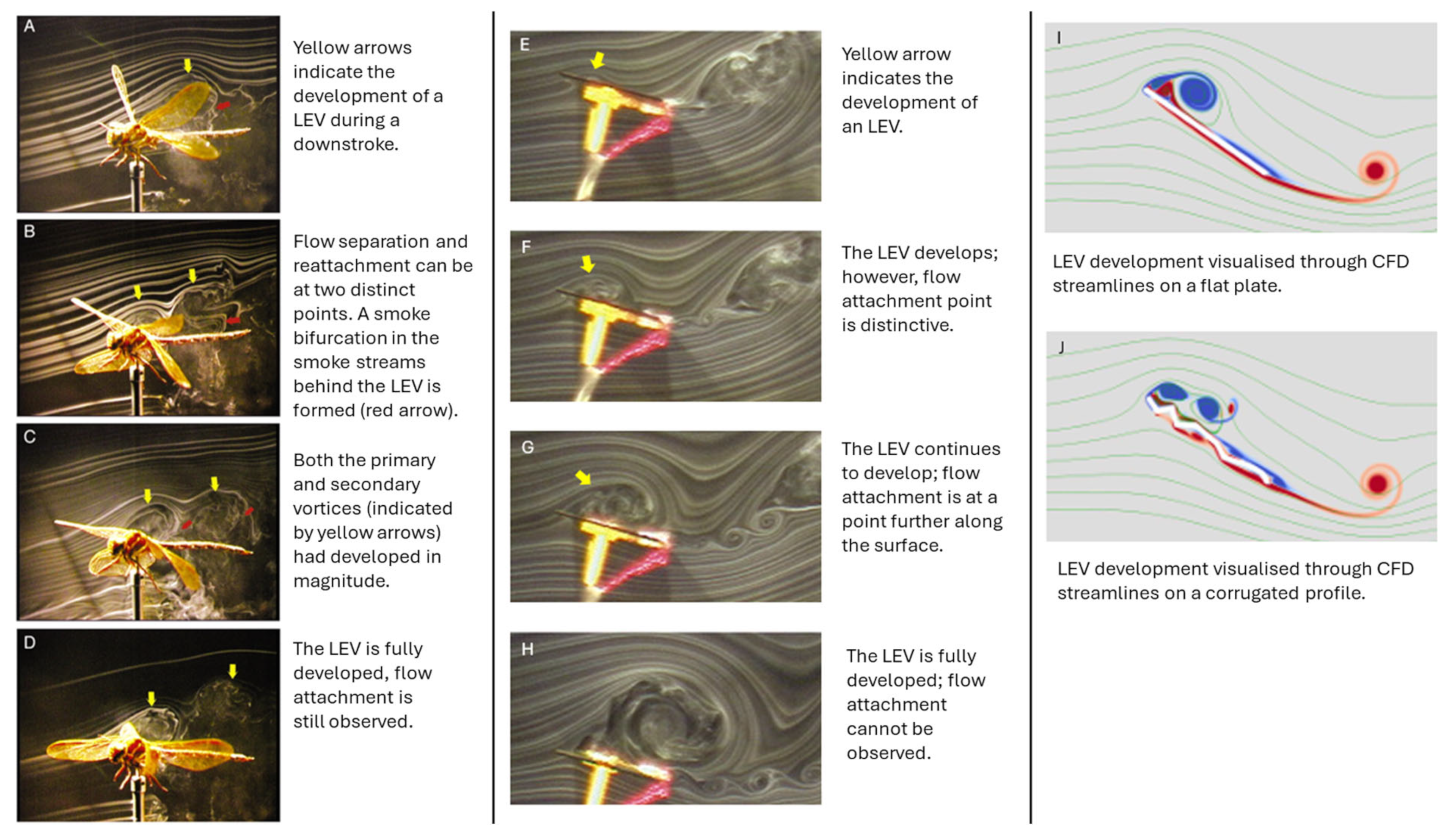
4.1.2. Leading Edge Vortex (LEV)

An LEV forms on the leading edge of profiles at low Reynolds numbers of 104 or lower. The revolving vortex location remains at the leading edge and allows for the upper surface flow to separate and reattach at the trailing edge. A wing with a stable LEV is, therefore, able to satisfy the Kutta condition at the trailing edge at angles of attack beyond which classical stall would occur for wings where no LEV is present; consequently, a substantial enhancement of the wing lift coefficient is achieved [96]. Figure 11 illustrates the development of a leading-edge vortex (LEV) on two profiles, visualized using smoke streamlines and CFD simulations.
The formation of LEVs during wing motion was discovered by Ellington [9]. By formulating a reduced-order model with six motors to flap the profile in mineral oil, the lift generated by varying wing motions could be determined. It was concluded that the primary contributor to the lift during hover is LEV generated.
Further research has been conducted on the formation of LEVs and their role in life enhancement in corrugated wings. The results conclude that the unique corrugated geometry offers a distinctive advantage in lift enhancement at low Reynolds numbers in comparison to traditional aerofoils and flat plates [97,98,99,100,101].
More recently, a study by [102], found that at Reynolds of 3500, 34,000, and 100,000 for a corrugated profile, the flow is trapped in the corrugations, and it is only at higher angles of attack that the flow contributes to the creation of the LEV. The research also found that a conventional profile experienced the smallest sized LEV, which was consistent with producing the lowest lift out of the corrugated and flat profiles within the study.
However, a study conducted by Abdizadeh et al. [60] focused on the formation of LEV on both a corrugated profile and a NACA 4412 but also considered ground effect. It was found that at lower Re (5 × 10³), like the previous studies, the corrugated profile created more concentrated and stronger vortices than the NACA profile. An opposite result is observed once the Reynolds is increased to 5 × 10⁴ however, with the NACA profile generating more lift than the corrugated profile. This was identified to be due to the high velocity flow the trapped eddy in the corrugation being unable to hold the vortices near the surface of the profile. Whilst the effect of LEVs is well documented to enhance lift, their effectiveness depends on flight conditions. At low altitudes, where air is denser, the wing would experience a higher Reynolds number. As shown, this will impact the lift generation. Therefore, integrating corrugated wings into flight vehicles requires careful consideration of the mission profile.

4.1.3. Lambda Vortex Breakdown

As the aerodynamically desirable LEV vortex is developed, a secondary vortex, the lambda vortex, also forms, rotating in the adverse direction to the LEV. The opposing development of the vortex breaks down and weakens the lift enhancement effect of the LEV stated above. The study by Fujita and Iima [91] investigated the differences in the formation of the additional vortex between a corrugated wing and a flat plate at Reynolds of 1500 and 4000 using CFD analysis. Through analysis of the results, Fujita concluded that the unique geometry of the corrugated profile induced variations in the air speed and level of turbulence experienced along the span of the profile. These distinctive variations hindered the lambda vortex from forming a stabilized and cohesive structure, resulting in a breakdown of the vortex. The LEV is therefore able to continue its lift enhancement effect on the corrugated profile. The result of this being that the performance of the corrugated wing was better when the AoA was greater than 30°.
The breakdown of the lambda vortex, however, was not the only desirable aerodynamic effect observed in the study. The paper highlighted the corrugation valley’s ability to ‘trap’ the broken vortex fragments within its valleys. Building on previous research by Fujita and Lima [103], this effect was presented as enhancing the lift. The ability to retain the fragments of the broken vortices was observed to create an averaged negative pressure area, producing a more adverse pressure gradient between the two surfaces, further enhancing lift production.
The research found that the corrugated wing recorded a larger maximum lift coefficient than the flat plate. The paper therefore suggests that, to enhance aerodynamic performance, the structure of the corrugated profile should be designed to encourage the lambda vortex to collapse and keep the split vortex inside the V-shaped structure.
The paper outlines several limitations, such as the study considering only two Reynolds numbers. At larger or smaller Reynolds numbers, the effect of flow viscosity could differ from the vortex motion analyzed. The study was also conducted using two-dimensional models, and it states that if expanded to three-dimensional analysis, a deeper understanding of the vortex interactions could be obtained.

4.1.4. Effect on Drag Reduction

A study conducted by Vargas et al. [5] utilized computational fluid dynamics to investigate the aerodynamic performance of dragonfly wings in gliding flight at ultra-low Reynold numbers. The study found that the aerodynamic performance was at least equivalent to and even sometimes better than a profiled aerofoil. At low angles of attack where the flow was attached to both surfaces of the wing profile, the corrugated profile experienced an increase in pressure drag. However, this effect was compensated by a concomitant decrease in the shear drag. This phenomenon was attributed to the presence of re-circularization zones within the valleys, which provided a negative shear drag contribution.
The lift enhancement of LEVs has been highlighted previously; however, due to the resultant pressure force acting normally on the wing surface, drag is also significantly increased by the presence of an LEV [103].
A key study into the effect of corrugated aerodynamics was undertaken by Levy and Seifert [44]. The study covered a Reynolds number range of 2000–8000. The research compared the aerodynamic performance of a simplified dragonfly model with a conventional low-speed wing design (Eppler-E61) through computational simulations. The results found that the corrugated wing not only generated significantly more lift but also experienced less drag. To further build on these findings, the researchers conducted further testing through means of wind tunnel and water channel testing. The results ultimately mirrored those observed through simulations. However, the key finding of this study was in the corrugated wing’s ability to reduce its drag to enhance overall flight performance. It was found that the corrugated profile generated small and temporary whirlpools (spanwise vortices) that reattached to the upper backside of the wing. This was shown to minimize the intensity of the vortices shed by the profile, reducing the overall drag force experienced. Further studies have also found corrugation to have a notable impact on reducing the overall profile drag of a wing [79,82,104].

4.2. Flow Separation and Stall

Flow separation is a critical parameter in dictating aerodynamic performance. It occurs when the airflow over a body detaches from the surface, creating a turbulent wake field. The result is a significant reduction in lift, an increase in drag, and the potential for aircraft stalls. Studies have found that corrugated profiles can delay the onset of flow separation until much higher angles of attack (AoA) compared to flat plates or traditional aerofoils [78,79]. The following subsections summarize the mechanisms behind the ability of the corrugated profile to maintain its desirable aerodynamic characteristics and avoid stalling.

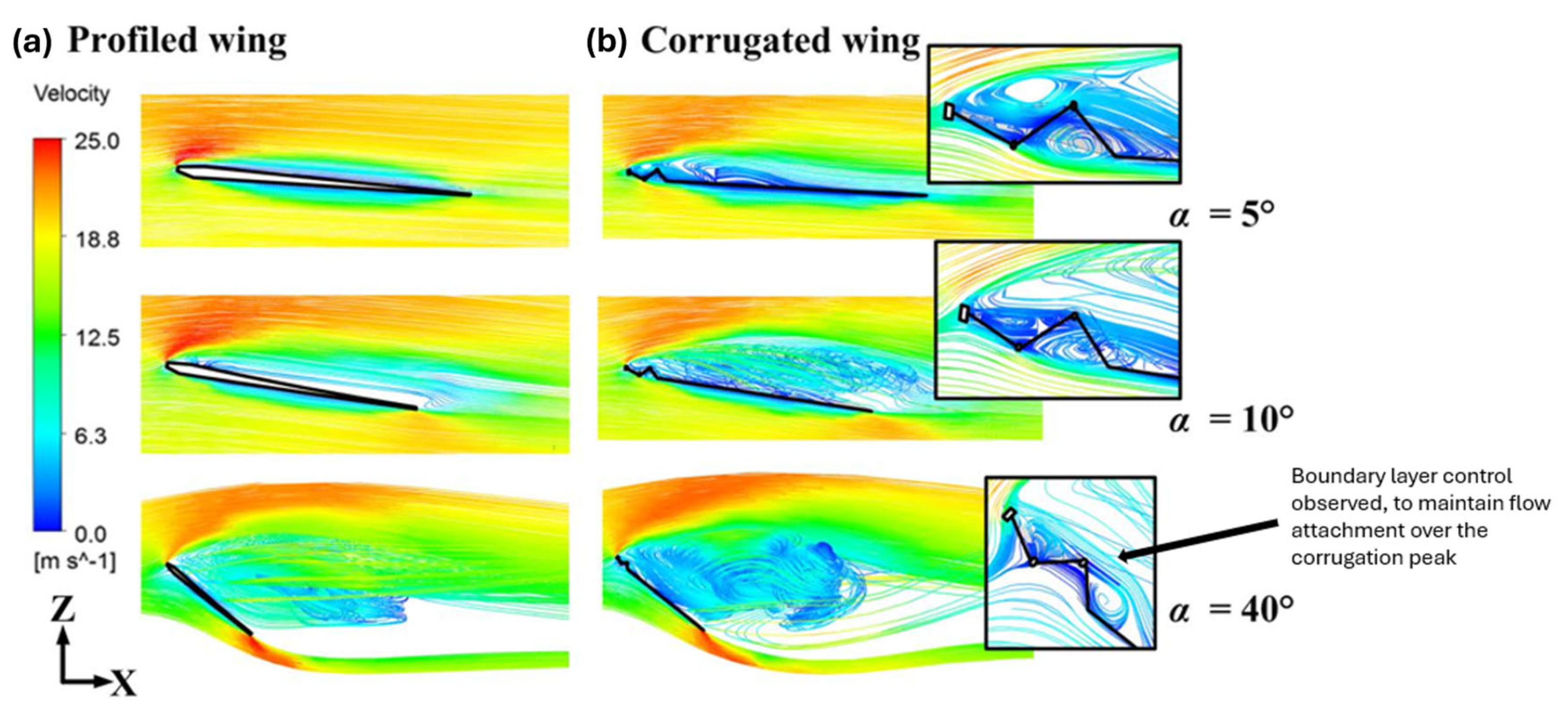
4.2.1. Boundary Layer Control

Research conducted by Ellington [9] suggested that the corrugated wing’s ability to delay flow separation is due to the ability of the geometry to influence the behavior of the flow’s boundary layer moving along the surface of the profile. As shown in Figure 12, at Reynolds numbers of 10,000 and lower, the rotating flow in the grooves generates negative viscous drag, but at higher Reynolds numbers, pressure drag becomes dominant, reducing the corrugated wing’s performance compared to the profiled wing [105].
Considering that boundary layer separation occurs along the profile surface, a significant decrease in lift and an increase in drag is observed. The findings of the research suggested that the corrugations have an effect in triggering an early transition of the flow. This promotes the transition in the flow from a laminar into a turbulent state at earlier AoA than conventional aerofoils can. Turbulence mixing is observed due to this transition, a phenomenon that delivers high-momentum fluid from the freestream to the profile wall. The additional momentum experienced allows the boundary layer to resist separation and retain its aerodynamic performance at angles where conventional profiles would experience separation and stall. Research conducted by Bauerheim [58] built directly on this, suggesting that the abrupt change induced by corrugation geometry destabilizes the shear layer of the boundary layer and freestream flow. This forms the mentioned recirculation zones, which were identified to have the ability to energize the boundary layer, further contributing to delaying flow separation. Beyond separation delay, research conducted by Lehmann et al. [78] suggested that corrugations have the potential to promote flow reattachment. Through wind tunnel testing it was observed that streamwise vorticity had the ability to draw separated flow back to the wing’s surface. The reattachment could improve stall characteristics. This mechanism was further identified as a key factor to the corrugated profile’s ability to maintain its aerodynamic advantages at high AoA detailed in [106,107].

4.2.2. Functionality

It must be noted that studies such as the one published by Sane [108] have attributed the dragonfly’s ability to delay flow separation to factors beyond corrugation. The research suggested that the natural twist in the corrugated profile helps manipulate the airflow, keeping it attached at the leading edge. This section will outline the unique aerodynamic functions enabled by wing corrugation.
A study outlined previously, by Salami et al. [80], noted the aerodynamic advantage of tandem wings. However, the study also found that tandem wings improve aerodynamic stability. This finding could potentially allow for stable hovering of the vehicle. Traditional aerofoils rely on constant forward motion to generate lift. So, this finding potentially identifies a distinctive advantage to integrating bio-inspired corrugated wings into current vehicles such as MAVs. Furthermore, the study by Alexander [109] presented the finding that dragonflies actively control their wing twist through muscle control, allowing them to further optimize their performance and delay flow separation during changes in angle of attack maneuvers. However, to replace this functionality within the current aircraft design would require the use of morphing wings. The suitability of this concept will be explored in subsequent sections.

5. Consequence of Angle of Attack (AoA)

Angle of attack is defined as the angle between installations in the relative wind in the plane of symmetry and the longitudinal axis of a body [110]. A well-documented relationship exists between the AoA and aerodynamic forces. An adverse pressure gradient produces an increasing amount of lift with increase in AoA until a critical point is reached. This section will review the existing research conducted on aerodynamic AoA studies on corrugated wings and how the performance varies compared to other researched profiles.
This section will also explore current studies which have gathered data on corrugated aerodynamics at a range of AoA, to identify the critical regions of operation and to high-light how viable corrugation aerodynamics are under various flight regimes. For general usefulness, Figure 13 provides key angle definitions that will be referenced throughout the text.

5.1. Role of AoA in Manoeuvrers

Accurately predicting corrugated wing performance requires a thorough understanding of the angle of attack (AoA) effects. AoA studies can define operational limits for bio-inspired wings, ensuring safe and efficient flight. This knowledge is critical for maneuvers exceeding conventional flight, such as vertical take-off, where high AoA lift generation is essential. Additionally, AoA analysis can identify optimal wing operating conditions by identifying the angles that maximize the lift coefficient to drag coefficient ratio ( C l C d ), a key performance parameter indicated in Table 1.

5.2. Effect of AoA on Boundary Layer Flow

A study by Lavimi et al. [111] analyzed the performance of a corrugated wing structure at various angles of attack using CFD. The study focused on the different physics of the flow at very high AoA. Results showed that the corrugation significantly improved lift by delaying flow separation and creating beneficial vortex patterns even at AoA as high as 30°. This was due to the development of a laminar bubble which affected turbulence and boundary layer development.
As seen in Figure 14, the increase in AoA for the corrugated profiles creates a more significant wake, as the corrugated profiles manipulate the boundary layer flow, mitigating flow separation more effectively than the flat plate. Additionally, the figure illustrates vortex development along the surface, with laminar separation bubbles forming at specific locations, increasing turbulence intensity and enhancing boundary layer stability. The vortices covering the aerofoil help delay flow separation in the corrugated profiles, contributing to a higher lift coefficient compared to the flat plate. Overall, research has shown that corrugated wings are less impacted by changes in AoA compared to profiles such as flat plates or conventional aerofoils at low Reynolds numbers [58,92,112,113]. This enhanced performance is attributed to the unique aerodynamic properties of the corrugated design.

5.3. Critical Angles of Attack

Critical angle of attack refers to the angle where airflow over the wing disrupts, causing a stall. Table 5 summarizes a wind tunnel study conducted by Kesel comparing corrugated profiles to a flat plate and an asymmetric aerofoil at a Reynolds number of 10,000 [1].
As seen from the Table 5, Kessel found that the corrugated profiles can achieve a higher lift generation at a higher AoA than the asymmetric profile (aerofoil). Although the flat plate shares the same critical angle as the corrugated profiles, two of the profiles have higher lift generation. The image below further captures the consequence of the increasing AoA on the flight of corrugated wings compared to a flat plate profile.
Across most angles of attack, a trend can be seen that the corrugated profile generates a greater gliding ratio than a flat plate, although at extreme angles the aerodynamic performance is similar. Unlike flat profiles, the corrugated design maintains a desired gliding ratio even at negative angles of attack (AoA). This versatility makes corrugated profiles well-suited for maneuvers requiring sharp AoA changes in both positive and negative directions. At an AoA of 0°, the corrugated profile can generate significantly more lift than the counter flat plate profile. As shown in Figure 15, Kessel [1] identifies a critical angle of attack at 8°, a value corroborated by various studies on corrugated aerodynamic profiles. Table 6 summarizes the critical angles of attack reported in different research studies, highlighting the consistency of findings across the field.

5.4. Consequence of AoA on Pressure Distribution

The corrugated wing’s ability to delay flow separation to outperform current wings has been highlighted, and the critical angles have been identified. However, it is important to explore the pressure distribution along the wing to understand where separation occurs and how this is influenced by a varying angle of attack.
As seen from Figure 16, a CFD study [111] reveals that the corrugated profile exhibits pressure drops in its valleys, whereas the flat profile maintains a mostly uniform pressure distribution along its surface. At higher angles of attack, the flat plate experiences flow separation, characterized by a reversal in pressure distribution along its upper surface. In contrast, the corrugated profile sustains a favorable pressure distribution and even demonstrates the ability to reattach flow at the rear of the profile. This indicates that the corrugated profile experiences fewer adverse effects from flow separation compared to the flat plate at high angles of attack. With an increased pressure differential, aerodynamic forces such as lift are enhanced, highlighting the corrugated profile’s ability to deliver superior performance across a range of AoA values.
The ability to retain flow attachment at high angles of attack is a key aerodynamic parameter, enabling the corrugated profile to outperform traditional wing designs in such conditions [38,98].
While the mechanisms behind the corrugated wing’s high AoA performance are well understood, the detailed pressure distribution across its surface remains largely unexplored. Previous studies have provided limited insight into the exact separation points along the corrugated profile under varying conditions. This gap in knowledge presents an opportunity to optimize wing geometries further, potentially unlocking even greater aerodynamic performance at higher angles of attack.

5.5. A Brief Note on Induced Errors

Many research papers utilize wind tunnel testing to capture corrugated aerodynamics. However, there is a large consequence of increasing AoA on experimentally induced errors. Wind tunnels operate through measurements of controlled airflow over a body. At high AoA, the area of the body exposed to the oncoming airflow is increased. This reduces the effective working area, which increases the velocity of the air as it flows over the model [41] and thus changes the pressure distribution. This can lead to inaccurate lift and drag measurements [115].
Wake blockage is a further error in wind tunnel testing; in a test section, a wake is formed behind the model which has a lower velocity and thus a higher pressure than the free stream [41]. This effect causes a pressure differential that affects the drag of the model. The larger the angle of attack, the more significant the discrepancy between the measured and actual forces. These errors must be considered when analyzing the consequence of AoA on corrugated aerodynamics, especially at high AoA, where the discrepancies are larger [116]. Moreover, this highlights the importance of using testing methods such as CFD and PIV to avoid these errors.

5.6. Vortex Shedding

Outlined in Section 4.1.4, a study conducted by Levy and Seifert [44] found that spanwise vortices help reduce the overall drag of a corrugated profile. However, this study also noticed interesting consequences of this phenomenon with varying AoA. By analyzing the mean lift against AoA for a Reynolds number of 6000, a dependence of lift amplitude on AoA was observed. It was found that the lift curve can be split into two distinctive regions. The first region, up to an incidence of 7° AoA, showed that the oscillations of the coefficient of lift as a function of time were small and constant. The second region, above 7°, found that the coefficient of lift suddenly grew because of increasing AoA. It is hypothesized that this growth is due to the production of a different vortex shedding mode, with larger amplitude and lower frequency.
As AoA continued to increase, a further increase in lift value was observed. Interestingly, the comparative aerofoil tested experienced a gradual increase in the coefficient of lift oscillations with increasing AoA. It was also observed that for the aerofoil, at low AoA (<0.7°), the transition to a different vortex shedding mode also appeared, causing flow separation from the lower surface of the technical aerofoil.

5.7. AoA on Tandem Wings

The study on tandem wings outlined in Section 3.3 conducted by Salami et al. [80], found that the AoA had a significant impact on the aerodynamic efficiency of the wings. The study found that at higher AoA, a greater pressure difference in the surface of the dragonfly wing was generated with higher angles of attack. Due to this, the lift increased with increasing AoA. However, in addition to this, the drag also increased with a positive AoA. These results validated those obtained in an earlier study by Bomphrey et al. [117]. The study measured aerodynamic coefficients at both varying AoA and also flapping frequencies. It was found that the higher frequencies correlated with a greater lift force than the lower frequency at all AoA up to 10°. The study managed to match the drag force of the MAV wing to one produced by a real dragonfly at natural wing frequency even at higher AoA (AoA > 10°). However, due to the flow separation and stall caused by the increasing AoA, the drag force increased dramatically. The hindwing has its stall between 10° and 12° AoA, whilst stall angles on the forewing were not found until 15° and 17°. It is stated that due to the flexible surface area, very high frequencies cause the MAV wing to have poor resistance to adverse pressure gradients at higher AoA. It was stated that the wing beat frequency does not have significant effects on L/D improvement at low AoA, which can be observed for high AoA. The critical gliding ratio angle of attack was found to be 10° out of those investigated. Although the paper has limitations due to the experiment only utilizing a setup with a corrugated profile, it provides valuable insights. However, it would benefit from further exploration with a comparative wing shape design alongside the corrugated profile. This would allow for a more comprehensive evaluation of the aerodynamic efficiency of the corrugated profile, particularly at AoA 5.8°, in comparison to other profiles at varying AoA. A more recent study, Ref. [88], explores how the angle of attack (AoA) and hindwing positioning in tandem flapping-wing arrangements affect aerodynamic performance, increasing lift by 78.1% with optimal setup and reducing it by 51.6% with poor arrangement.
It is important to consider that, due to the flapping nature of dragonfly wings, the wings experience a variety of angles of attack changes through a flight regime. The following image shows the variance of wing deformation throughout hovering flight maneuvers.
Figure 17 illustrates the spatial deformations and deflection of dragonfly wings during hovering, highlighting the load distribution and deformation during both upstroke and downstroke. The study [11] found the deformations during upstroke to be approximately twice as large when compared to the downstroke motion. The paper concludes that to be able to deal with the deformation due to changes in AoA a sophisticated aeroelastic design and actuation of the wings is required. A stiffer wing would experience higher performance due to less energy being dissipated due to deformation with changes in AoA. Another study [118] found that during the upstroke, inertial forces dominate wing deformation, while aerodynamic forces lead to downstroke. Inertial deformation increases sixfold with rapid rotation, influencing dragonfly wing mechanics and design inspiration. The structural deformation of flapping motion is a key area of corrugated flight which must be explored further. Through design optimization, more efficient MAV and UAV vehicles may be designed.

6. Morphing Wings

The concept of introducing morphing wings is an extension of bio-inspired wing concepts currently being studied to aid the development and improvement of current conventional aircraft designs. The technological concept is to develop aircraft wings that can dynamically change shape during flight to achieve performance optimization under different flight regimes and conditions [119].
Morphing wings aim to mimic the adaptability of insect and bird flight found in nature. This includes the ability to adapt wingspan, sweep angle, and wing twist. The technology has the potential to improve aircraft maneuverability and efficiency. However, with this potential comes a technological barrier, as challenges arise in implementing the technology into current aircraft wings. The technology relies on a highly advanced actuation system to control the shape of the wings and any fluctuations in design. Additionally, the addition of a wing morphing process increases the complexity of structural integration substantially, requiring research into materials and design procedures. Moreover, the addition of morphing technology to wings requires the development of control algorithms to enable transitions in wing shape. This presents a substantial computational challenge to overcome.
The following subsections will explore current research on morphing corrugated wings. An aircraft could be developed to combine exceptional performance in low Reynolds number flight and high angle of attack maneuverability by utilizing a corrugated configuration and adapting to high Reynolds number flight through a transition to traditional aerofoil designs. For example, the Figure 18 illustrates such a potential design that uses corrugated wing morphing aerodynamics to optimize performance across various flight regimes, starting with a low Reynolds number configuration and transitioning to a traditional aerofoil for high Reynolds number flight.

6.1. Morphing with Corrugation in Nature

Insects possessing corrugated wings, such as dragonflies, exhibit passive morphing during flight due to the flexibility of their wing membranes and veins. While the muscles at the base of their wings enable independent forewing and hindwing movement, the passive deformation of the wing structure occurs in response to aerodynamic forces. This spontaneous cambering improves aerodynamic efficiency and compensates for bending deformation caused by air pressure, highlighting the adaptive nature of their wing design [30,120,121,122].

Flow Sensing, Active Flow Control, and Application to Wing Morphing

As stated in the previous section, the dragonfly can passively morph its wings to enhance the aerodynamic capability of its corrugated wings. It is important to understand how this passive effect is possible and how it can be integrated into bio-inspired aircraft.
A detailed study investigating the aerodynamic sensing capabilities of dragonfly wings [123] used neural activation models and CFD simulations to determine that strategically positioned bristles on wing ridges can effectively capture aerodynamic flight parameters. The dragonfly’s wings, including bristle–bump complexes and leading-edge serrations, act as a biological filter, enhancing sensor specificity. The research highlighted the potential of bio-inspired flow sensors, which could enable real-time monitoring of flight parameters and initiate wing morphing to suit the desired flight regime. Using a leading-edge sensor, active control of wing morphing could be implemented, as shown in Figure 19.
Dragonflies exhibit fixed-wing shapes that cannot actively morph like those of birds or bats. Despite this limitation, they achieve exceptional flight control through unique mechanisms. Using two pairs of independently controlled wings, dragonflies combine the passive mechanical properties of their wings, including structural features like corrugation, with active muscle control to adjust flight dynamics [124]. Nevertheless, exploring and understanding active flow control and wing morphing is essential for enhancing aerodynamic efficiency in bio-inspired designs like Micro Air Vehicles (MAVs). Birds, bats, and insects use morphing wings to adapt their flight mechanics, often through muscle-controlled flexing or passive deformations [70]. For example, Liu [125] examined the active and passive control of dragonfly wings, demonstrating that passive rotation dominates most of the wing’s flapping cycle, with muscle-driven adjustments enhancing vortex strength at upstroke reversal. Previously, [86] modeled the dynamic morphing of wings to increase lift by altering the flow structure and wing area. As outlined earlier, the complex surface corrugations on dragonfly wings have been shown to potentially enhance aerodynamic performance by increasing spanwise stiffness [32,86,126]. While many studies suggest that such morphing mechanisms improve stability and performance, e.g., [28], some computational models argue that corrugated surfaces do not necessarily outperform smooth plates [127]. However, active flow control and morphing remain significant focuses in biomimetic design, offering the potential for more efficient flight in UAVs and MAVs.

6.2. Aerodynamic Coefficients of Corrugated Morphing Wings

A study explored corrugated composites for morphing structures by adding a corrugated section to the trailing edge of an aerofoil, allowing a 4% change in chord length and 12° deflections. Wind tunnel testing showed that the concept worked well at low speeds, reducing drag in the corrugated trailing edge with minimal impact on structural performance [128]. A subsequent study [129] tested a NACA 0012 aerofoil, finding that while corrugation had adverse effects on aerodynamic performance, it retained flexibility in morphing.
From the perspective of static aeroelastic behavior, the work [130] uses a nonlinear aeroelastic framework to model the aerodynamic and structural responses of these wings under large deformations. The findings indicate that corrugations can negatively impact aerodynamic performance, but proper design—such as low amplitude, low wavelength corrugations and recessing them within the aerofoil—can mitigate these effects. The study also demonstrates the framework’s ability to analyze complex aeroelastic characteristics of morphing wings. A study [131] further explored the aerodynamic performance of aerofoils with corrugated skins in the aft 1/3 of the chord. It showed that such configurations caused a reduction in lift slope (d C l /dα) and an increase in drag at zero lift ( C d 0 ). Figure 20 shows the experimental wing profiles and results emanating from the results of [130]. However, these effects could be minimized with careful design of corrugation shape, wavelength, and Reynolds number. Low amplitude and low wavelength corrugations provided the best results, and recessing corrugations within the aerofoil shape restored lift and drag to levels similar to a smooth aerofoil. The study also highlighted that morphing aerofoils with corrugations offer potential for improved performance with the right design considerations.

6.3. Structural Considerations of Corrugated Morphing Wings from an Aerodynamic Perspective

Although this review paper primarily focuses on aerodynamics, the structural design of corrugated wings plays a significant role in their performance. The structural characteristics, including the ability to adapt and distribute loads, directly influence aerodynamic behavior. Therefore, we will briefly discuss the key aspects of the corrugated structural considerations from the perspective of aerodynamics, as it is crucial for the effectiveness of a morphing wing structure.
Morphing aircraft wings adapt mid-flight to enhance aerodynamic performance, adjusting span, chord, twist, or camber to optimize lift, reduce drag, and improve maneuverability. A key challenge is designing skins that combine stiffness for aerodynamic loads with flexibility for shape changes. Corrugated skins, with their anisotropic properties, provide an effective solution, offering flexibility, structural strength, energy absorption, and aerodynamic efficiency while being easy to fabricate [127]. From an aerodynamic perspective, cyclic stresses on morphing corrugated skins—arising from aerodynamic forces or actuator-induced loads—are critical for understanding fatigue behavior. Dayyani et al. [132] found that elastomeric coatings on corrugated skins dissipate energy through the ‘stress-softening’ phenomenon known as the Mullins effect, even before reaching the elastic limit, due to micro-damage. This highlights the importance of material resilience under repeated aerodynamic loading and the need for coatings that balance energy dissipation with structural integrity to maintain aerodynamic efficiency and durability in morphing applications.
A study by [133] used MATLAB to perform beam-element to optimize in-plane stiffness whilst minimizing skin mass. The study found a large potential in corrugated skin in having the ability to increase bending stress which allowed for fewer structural stringers to be required to actuate morphing. This led to a lighter overall structure. In another work by [134], it was found that through prototyping, that additional structural support is required to maintain the load bearing capability of a none-morphing wing. Thill et al. [128] demonstrated the use of composite corrugated skins for a morphing trailing edge of a NACA 0024 aerofoil, achieving camber morphing and chord extension using a scissor mechanism. Despite achieving up to 4% stretch and 12° deflection, the lack of internal support led to skin buckling under aerodynamic and structural loads, causing increased drag. Yokozeki et al. [131] integrated carbon fiber corrugated sheets and servomotor actuation for a camber morphing aerofoil, enhancing lift but encountering drag issues due to an uneven lower surface. Dayyani et al. [133] emphasized the interaction of corrugated skins with internal aeroelastic structures, proposing elastomer-coated designs for improved compliance [133]. Ursache et al. [135] developed a winglet design by incorporating a corrugated skin to allow flexible partition movement, enabling dynamic shape adaptation while maintaining aerodynamic efficiency. Figure 21 illustrates the design, achieving a 0.52 rad dihedral angle change and 0.055 rad twist angle change, showcasing the potential of corrugated structures in adaptive wing technologies. Fincham et al. [136] noted significant aerodynamic penalties from corrugation depth while advocating smooth coverings to mitigate drag.
The recent review of Ameduri and Concilio [119] effectively shows that morphing wing systems, including adaptive trailing and leading edges, can enhance aerodynamic efficiency, with benefits like a 3% fuel reduction from trailing edges and a 5% reduction from leading edges by maintaining laminar flow. Winglets and rudders improve fuel savings and operational capabilities, such as reduced runway requirements. It critically examines the interplay between innovation and regulatory challenges, addressing issues like load transmission, skin flexibility, scalability, and aeroelastic behavior, essential for advancing morphing technology in environmentally sustainable aviation. For a deeper understanding of these challenges, the authors direct readers to the original work, which explores the key obstacles in the development of morphing wings [119].

7. Concluding Reflections, Challenges, and Visions for the Future

The field of corrugated wing aerodynamics has grown massively; for instance, a simple Google Scholar search for ‘corrugated wing aerodynamics’ shows that approximately 2260 articles were published between 2020 and 1 January 2025, while 1600 articles were published from 2015 to 2019. This represents a remarkable trajectory of interest and innovation spanning multiple disciplines and research methodologies in the last decade. The scope of this review, along with its coverage of numerical and experimental methods in the aerodynamics of corrugated wings, selected advances and problems particularly timely to the progress from the past, present advancements, and potential future needs of this field.
Nonetheless, though, fortunately, a large number of researchers have already made great efforts in this field and their work is of substantial help in its progression, with due respect, to cover all the papers within the scope of this review would almost be impossible. Considering that this review focuses mainly on the situations and developments from the recent past, present, and reviews of future advancements in the field of aerodynamics of corrugation in wings, the information provided herein cannot be considered comprehensive, as it is ever evolving. Notwithstanding the level of technical complexities involved due to the great number of works and their contribution to a wide variety of multiphysics methods, it is not possible to integrate all contributions. Additionally, the rapid rate of development of computational tools and experimental methods often leaves early foundational work underexplored considering more recent breakthroughs. The current research overwhelmingly concentrates on skin corrugation for simple classes of aerofoils, such as trailing edges, where the aerodynamic advantages, like drag reduction, are understood to be high for a low Reynolds number regime. One such classic is the early work by Rechenberg in the 1960s, who used innovative analog randomization techniques to optimize corrugated plate configurations for aerodynamic drag reduction. Their work, although groundbreaking at such an era, has received limited attention but is a steppingstone towards the current machine learning (ML) applications in aerodynamic optimization, as indicated by [137]. For more information we direct readers to references [138,139]. At present, employing the improvement of machine learning (ML) and computational fluid dynamics (CFD), the prospect of optimizing corrugated geometries has the potential to be significantly improved [137], which can be beneficial to quantitative optimization of lift-to-drag ratios.
Despite much progress, some fundamental challenges remain. Current morphing wing studies have mostly been confined to localized skin wrinkling. In the future, work will be necessary to explore the feasibility of designing whole wings that transition between corrugated profiles and classical aerofoils to fully realize the technology potential. This morphing will enshrine the possibility of restoring the advantage of corrugation at low Reynolds numbers while balancing the advantages of a traditional corrugated aerofoil’s efficiency at higher Reynolds numbers and thus the best performance over the entire envelope of flight regimes. Bio-inspired designs, e.g., those inspired by dragonflies and fly wings, provide an intrinsic build framework for these versatile systems [53,140]. The use of ML in aerodynamic studies holds great promise. For instance, algorithms such as double deep Q-networks (DDQN) have been successfully tailored to minimize those corrugated aerofoil configurations that maximize lift-to-drag performance, achieving improvement of up to 5.6% [141]. Possible future developments in this area may involve real-time virtual representations of morphing wing designs using data updates from sensors coupled with AI-based models through physics informed fluid–structure interaction, leading to digital twins. Yet, such computational capabilities need to be accompanied by rigorous experimental validation through, for example, PIV, wind tunnel measurements, and high-fidelity 3D-printed prototypes [113,142]. These approaches will help fill the discrepancy between theoretical models and applications.
Fluid–structure interaction is, to this day, one of those most challenging elements that needs to be determined in the case of corrugated wings, and even more so under dynamic flight conditions, and when analyzed from a tandem wing’s perspective. While experimental and computational studies have advanced significantly, some discrepancies remain in modeling transition, vortex interactions, and aerodynamic efficiency at different Reynolds numbers. Corrugation has been previously demonstrated to increase mechanical stiffness but to retain enough flexibility to allow for effective load transfer in flapping and during gusty exposures leading to wing damage [140,143]. High-fidelity FSI models involving multiphysics phenomena such as aeroacoustics and thermal effects will play an increasing role in the design process of wing shape optimization for noise management and energy efficiency. This integration will also broaden the scope for the use of corrugated wings in contemporary air transportation, from small UAVs to larger commercial aircraft. Sustainability is one of the key concerns for future aerospace systems, and corrugated morphing technologies could play a role in achieving these objectives, though further validation is needed. Lightweight, bio-inspired-based materials and morphers contribute to new avenues for profound energy savings as well as emissions reduction, and aerodynamic efficiency. Research on MAVs and UAVs reveals the possibility of ultra-lightweight materials and composite materials to build strong, low-drag structures [119,144]. With the advancements in additive manufacturing technologies [145], the potential for high-fidelity, large-scale production of corrugated wing shapes shall only continue to grow, thereby incentivizing aerodynamic development for each application explored.
Standardization and benchmarking shall be crucial in promoting research into corrugated wings. The current discrepancy in geometries, testing procedures, and performance measures hampers the comparative analysis. For the creation of unified datasets and benchmarks, it is essential for experimentalists and computational researchers to ensure the reproducible, consistent evaluation of new designs. The incorporation of biological data, such as 3D scans of natural wings, provides a strong basis from which to combine biological realism with engineering realism [31,43]. Looking forward, the key to facing these challenges will undoubtedly be an interdisciplinary collaboration among researchers, scientists, and technologists supported by industries and governments. Extending the intersection of takeaways from biology, materials science, artificial intelligence, and engineering, future work in aerodynamic and aeroelastic-based optimization can continue to stretch the limits of what is feasible. As presented in this work, the hybrid models, which combine AI, CFD, FSI, and aeroacoustics simulations, would be the most effective toward achieving real-time, adaptive solutions for UAVs, MAVs, and others. Also, investigations into corrugated wing geometry as applied to larger scales, e.g., commercial aircraft and renewables, is a promising field in which their influence can be extended.
As a closing remark, the developments of the past 10 years in corrugated wing aerodynamics all highlight the disruptive impact that this technology will be able to bring about in the next decade. It has transitioned from the basic experimental history of the last decades to the contemporary, advanced, AI-based optimization, and the discipline has evolved into a multidisciplinary activity combining natural inspired engineering with engineering innovation. Reflecting on the existing challenges in scalability, morphing, and experimental validation, corrugated wings offer a promising aerodynamic concept that may contribute to future aerial vehicle designs by improving sustainability and efficiency, though further research is needed to address these limitations.

Author Contributions

Conceptualization, A.A. and H.V.; methodology, E.L., H.V. and A.A.; software, H.V.; formal analysis, H.V. and E.L.; investigation, E.L., A.A. and H.V.; resources, H.V.; data curation, H.V.; writing—original draft preparation, E.L. and H.V.; writing—review and editing, A.A. and H.V.; visualization, H.V. and A.A.; supervision, H.V. and A.A.; project administration, H.V.; funding acquisition, H.V. All authors have read and agreed to the published version of the manuscript.

Funding

This research received no external funding.

Data Availability Statement

Not applicable.

Acknowledgments

H.V. acknowledges the support of Sheffield Hallam University’s department (Research Innovation and Knowledge Exchange, RIKE) internal grant, that enabled E.L. to conduct the review work and contribute to the writing of this paper.

Conflicts of Interest

The authors declare no conflicts of interest.

Nomenclature

The following abbreviations are used in this manuscript:
UAVUnmanned Aerial Vehicle
MAVMicro Aerial Vehicle
CFDComputational Fluid Dynamics
PIVParticle Image Velocimetry
AoAAngle of Attack
FSIFluid Structure Interaction
DDQNDouble Deep Q-Networks
MLMachine Learning
AIArtificial Intelligence
LEVLeading Edge Vortex
TEVTrailing Edge Vortex
FVMFinite Element Method
FEAFinite Element Analysis
CTComputed Tomography
LESLarge Eddy Simulation
ILESImplicit Large Eddy Simulation
GPUGraphics Processing Unit
IBMImmersed Boundary Method
FW-HFfowcs-Williams and Hawkings
2DTwo dimensions
3DThree dimensions
C d Coefficient of drag
C l Coefficient of lift
C p Pressure coefficient
C f Skin friction coefficient
R e Reynolds number
S t Strouhal number
D Drag force
L Lift force
A Area
p Pressure
p Ambient pressure
ρ Density of the fluid
τ w Wall shear stress
l Characteristic length scale
f Frequency of vortex shedding
V Flow velocity
ψ Phase angle
C H Horizontal force coefficient

References

  1. Kesel, A.B. Aerodynamic Characteristics of Dragonfly Wing Sections Compared with Technical Aerofoils. J. Exp. Biol. 2000, 203, 3125–3135. [Google Scholar] [CrossRef] [PubMed]
  2. Abd El-Latief, M.E.; Elsayed, K.; Madbouli Abdelrahman, M. Aerodynamic study of the corrugated airfoil at ultra-low Reynolds number. Adv. Mech. Eng. 2019, 11, 1687814019884164. [Google Scholar] [CrossRef]
  3. Xia, Y.; Bilgen, O.; Friswell, M.I. The effect of corrugated skins on aerodynamic performance. J. Intell. Mater. Syst. Struct. 2014, 25, 786–794. [Google Scholar] [CrossRef]
  4. Tamai, M.; Wang, Z.; Rajagopalan, G.; Hu, H.; He, G. Aerodynamic Performance of a Corrugated Dragonfly Airfoil Compared with Smooth Airfoils at Low Reynolds Numbers. In Proceedings of the 45th AIAA Aerospace Sciences Meeting and Exhibit, Reno, NV, USA, 8–11 January 2007. [Google Scholar]
  5. Vargas, A.; Mittal, R.; Dong, H. A computational study of the aerodynamic performance of a dragonfly wing section in gliding flight. Bioinspir. Biomim. 2008, 3, 026004. [Google Scholar] [CrossRef]
  6. Kim, W.-K.; Ko, J.H.; Park, H.C.; Byun, D. Effects of corrugation of the dragonfly wing on gliding performance. J. Theor. Biol. 2009, 260, 523–530. [Google Scholar] [CrossRef]
  7. Li, Q.; Zheng, M.; Pan, T.; Su, G. Experimental and Numerical Investigation on Dragonfly Wing and Body Motion during Voluntary Take-off. Sci. Rep. 2018, 8, 1011. [Google Scholar] [CrossRef]
  8. Brodskij, A.K.; Brodskij, A.K. The Evolution of Insect Flight; Oxford science publications; Oxford University Press: Oxford, UK, 1996; ISBN 978-0-19-850089-6. [Google Scholar]
  9. Wakeling, J.M.; Ellington, C.P. Dragonfly Flight: I. Gliding Flight and Steady-State Aerodynamic Forces. J. Exp. Biol. 1997, 200, 543–556. [Google Scholar] [CrossRef]
  10. Liu, C.; Chen, G.; Wang, Q.; Sun, L.; Wang, K. A study on the aerodynamic behaviors learned from microscopy imaging of beetle corrugated hindwing. Microsc. Res. Techol. 2024, 87, 1822–1835. [Google Scholar] [CrossRef]
  11. Jongerius, S.R.; Lentink, D. Structural Analysis of a Dragonfly Wing. Exp. Mech. 2010, 50, 1323–1334. [Google Scholar] [CrossRef]
  12. Forbes, W.T.M. The Origin of Wings and Venational Types in Insects. Am. Midl. Nat. 1943, 29, 381. [Google Scholar] [CrossRef]
  13. Fage, A. The Smallest Size of a Spanwise Surface Corrugation Which Affects Boundary Layer Transition on an Aerofoil. Aeronautical Research Council Reports & Memoranda 1943. Available online: https://reports.aerade.cranfield.ac.uk/handle/1826.2/3987 (accessed on 14 February 2025).
  14. Wood, D. Tests of Large Airfoils in the Propeller Research Tunnel, Including Two with Corrugated Surfaces; Technical Report; NASA: Greenbelt, MD, USA, 1930. Available online: https://ntrs.nasa.gov/citations/19930091406 (accessed on 11 March 2025).
  15. Barnes, C.J.; Visbal, M.R. Numerical exploration of the origin of aerodynamic enhancements in [low-Reynolds number] corrugated airfoils. Phys. Fluids 2013, 25, 115106. [Google Scholar] [CrossRef]
  16. Moscato, G.; Romano, G. Biomimetic Wings for Micro Air Vehicles. Biomimetics 2024, 9, 553. [Google Scholar] [CrossRef] [PubMed]
  17. Ma, Z.; Krings, A.W.; Hiromoto, R.E. Dragonfly as a model for UAV/MAV flight and communication controls. In Proceedings of the 2009 IEEE Aerospace conference, Big Sky, MT, USA, 7–14 March 2009; pp. 1–8. [Google Scholar]
  18. Adak, R.; Mandal, A.; Saha, S. Aerodynamic Performance of a Tandem Wing Configuration Inspired from Dragonfly Gliding Flight for MAV Application. In Fluid Mechanics and Fluid Power; Singh, K.M., Dutta, S., Subudhi, S., Singh, N.K., Eds.; Lecture Notes in Mechanical Engineering; Springer Nature: Singapore, 2024; Volume 2, pp. 409–418. ISBN 978-981-9957-51-4. [Google Scholar]
  19. Gaissert, N.; Mugrauer, R.; Mugrauer, G.; Jebens, A.; Jebens, K.; Knubben, E.M. Inventing a Micro Aerial Vehicle Inspired by the Mechanics of Dragonfly Flight. In Towards Autonomous Robotic Systems; Natraj, A., Cameron, S., Melhuish, C., Witkowski, M., Eds.; Lecture Notes in Computer Science; Springer: Berlin/Heidelberg, Germany, 2014; Volume 8069, pp. 90–100. ISBN 978-3-662-43644-8. [Google Scholar]
  20. Hu, Y.; Ru, W.; Liu, Q.; Wang, Z. Design and Aerodynamic Analysis of Dragonfly-like Flapping Wing Micro Air Vehicle. J. Bionic Eng. 2022, 19, 343–354. [Google Scholar] [CrossRef]
  21. Zoell, W. Leonardo Da Vinci’s Mechanical Dragonfly. The Great Canadian Model Builders Web Page. 2016. Available online: https://thegreatcanadianmodelbuilderswebpage.blogspot.com/2016/03/leonardo-da-vincis-mechanical-dragonfly.html (accessed on 11 March 2025).
  22. Chitsaz, N.; Siddiqui, K.; Marian, R.; Chahl, J. An experimental study of the aerodynamics of micro corrugated wings at low Reynolds number. Exp. Therm. Fluid Sci. 2021, 121, 110286. [Google Scholar] [CrossRef]
  23. Chahl, J.; Chitsaz, N.; McIvor, B.; Ogunwa, T.; Kok, J.-M.; McIntyre, T.; Abdullah, E. Biomimetic Drones Inspired by Dragonflies Will Require a Systems Based Approach and Insights from Biology. Drones 2021, 5, 24. [Google Scholar] [CrossRef]
  24. Du, G.; Sun, M. Effects of wing deformation on aerodynamic forces in hovering hoverflies. J. Exp. Biol. 2010, 213, 2273–2283. [Google Scholar] [CrossRef]
  25. Calafate, C.T.; Tropea, M. Unmanned Aerial Vehicles—Platforms, Applications, Security and Services. Electronics 2020, 9, 975. [Google Scholar] [CrossRef]
  26. Badrya, C.; Govindarajan, B.; Chopra, I. Basic Understanding of Unsteady Airfoil Aerodynamics at Low Reynolds Numbers. In Proceedings of the 2018 AIAA Aerospace Sciences Meeting, Astronautics, Kissimmee, FL, USA, 8–12 January 2018. [Google Scholar]
  27. Winslow, J.; Otsuka, H.; Govindarajan, B.; Chopra, I. Basic Understanding of Airfoil Characteristics at Low Reynolds Numbers (104–105). J. Aircr. 2018, 55, 1050–1061. [Google Scholar] [CrossRef]
  28. Murphy, J.; Hu, H. An Experimental Investigation on a Bio-inspired Corrugated Airfoil. In Proceedings of the 47th AIAA Aerospace Sciences Meeting including The New Horizons Forum and Aerospace Exposition, Orlando, FL, USA, 5–8 January 2009. [Google Scholar]
  29. Salami, E.; Ward, T.A.; Montazer, E.; Ghazali, N.N.N. A review of aerodynamic studies on dragonfly flight. Proc. Inst. Mech. Eng. Part C J. Mech. Eng. Sci. 2019, 233, 6519–6537. [Google Scholar] [CrossRef]
  30. Wang, W.; Yuan, G. Review on the Structure Design of Morphing Winglets. Aerospace 2024, 11, 1004. [Google Scholar] [CrossRef]
  31. Liu, H.; Wang, S.; Liu, T. Vortices and Forces in Biological Flight: Insects, Birds, and Bats. Annu. Rev. Fluid Mech. 2024, 56, 147–170. [Google Scholar] [CrossRef]
  32. Shyy, W. Aerodynamics of Low Reynolds Number Flyers; Cambridge aerospace series; Cambridge University Press: Cambridge, UK, 2008; ISBN 978-0-521-20401-9. [Google Scholar]
  33. Rees, C.J.C. Aerodynamic properties of an insect wing section and a smooth aerofoil compared. Nature 1975, 258, 141–142. [Google Scholar] [CrossRef] [PubMed]
  34. Rees, C.J.C. Form and function in corrugated insect wings. Nature 1975, 256, 200–203. [Google Scholar] [CrossRef]
  35. Azuma, A.; Watanabe, T. Flight Performance of a Dragonfly. J. Exp. Biol. 1988, 137, 221–252. [Google Scholar] [CrossRef]
  36. Wakeling, J.M.; Ellington, C.P. Dragonfly Flight: II. Velocities, Accelerations and Kinematics of Flapping Flight. J. Exp. Biol. 1997, 200, 557–582. [Google Scholar] [CrossRef]
  37. Wakeling, J.M.; Ellington, C.P. Dragonfly Flight: III. Lift and Power Requirements. J. Exp. Biol. 1997, 200, 583–600. [Google Scholar] [CrossRef]
  38. Hu, H.; Tamai, M. Bioinspired Corrugated Airfoil at Low Reynolds Numbers. J. Aircr. 2008, 45, 2068–2077. [Google Scholar] [CrossRef]
  39. Murphy, J.T.; Hu, H. An experimental study of a bio-inspired corrugated airfoil for micro air vehicle applications. Exp. Fluids 2010, 49, 531–546. [Google Scholar] [CrossRef]
  40. Guilarte Herrero, A.; Noguchi, A.; Kusama, K.; Shigeta, T.; Nagata, T.; Nonomura, T.; Asai, K. Effects of compressibility and Reynolds number on the aerodynamics of a simplified corrugated airfoil. Exp. Fluids 2021, 62, 63. [Google Scholar] [CrossRef]
  41. Placek, R. Errors and problems while conducting research studies in a wind tunnel—selected exaples. Pr. Inst. Lotnictwa 2016, 245, 169–177. [Google Scholar] [CrossRef]
  42. Özer, Ö.; Quinn, M.K. Progress towards a Miniaturised PIV System. Sensors 2022, 22, 8774. [Google Scholar] [CrossRef] [PubMed]
  43. Basri, E.I.; Basri, A.A.; Ahmad, K.A. Computational Fluid Dynamics Analysis in Biomimetics Applications: A Review from Aerospace Engineering Perspective. Biomimetics 2023, 8, 319. [Google Scholar] [CrossRef] [PubMed]
  44. Levy, D.-E.; Seifert, A. Simplified dragonfly airfoil aerodynamics at Reynolds numbers below 8000. Phys. Fluids 2009, 21, 071901. [Google Scholar] [CrossRef]
  45. Levy, D.-E.; Seifert, A. Parameter study of simplified dragonfly airfoil geometry at Reynolds number of 6000. J. Theor. Biol. 2010, 266, 691–702. [Google Scholar] [CrossRef]
  46. Zhang, J.; Lu, X.-Y. Aerodynamic performance due to forewing and hindwing interaction in gliding dragonfly flight. Phys. Rev. E 2009, 80, 017302. [Google Scholar] [CrossRef]
  47. Hord, K.; Liang, Y. Numerical Investigation of the Aerodynamic and Structural Characteristics of a Corrugated Airfoil. J. Aircr. 2012, 49, 749–757. [Google Scholar] [CrossRef]
  48. Meng, X.G.; Sun, M. Aerodynamic effects of wing corrugation at gliding flight at low Reynolds numbers. Phys. Fluids 2013, 25, 071905. [Google Scholar] [CrossRef]
  49. Lian, Y.; Broering, T.; Hord, K.; Prater, R. The characterization of tandem and corrugated wings. Prog. Aerosp. Sci. 2014, 65, 41–69. [Google Scholar] [CrossRef]
  50. Chen, Y.H.; Skote, M. Gliding performance of 3-D corrugated dragonfly wing with spanwise variation. J. Fluids Struct. 2016, 62, 1–13. [Google Scholar] [CrossRef]
  51. Ho, W.; New, T. Unsteady numerical investigation of two different corrugated airfoils. Proc. Inst. Mech. Eng. Part G J. Aerosp. Eng. 2017, 231, 2423–2437. [Google Scholar] [CrossRef]
  52. Khan, M.A.; Padhy, C. Aerodynamic and structural analysis of bio-mimetic corrugated wing. Fluid Mech. Res. Int. J. 2019, 3, 61–67. [Google Scholar] [CrossRef]
  53. Stelzer, V.; Krenkel, L. 2D numerical investigations derived from a 3D dragonfly wing captured with a high-resolution micro-CT. Technol. Health Care 2021, 30, 283–289. [Google Scholar] [CrossRef]
  54. Zhang, Q.; Xue, R.; Li, H. Aerodynamic Exploration for Tandem Wings with Smooth or Corrugated Surfaces at Low Reynolds Number. Aerospace 2023, 10, 427. [Google Scholar] [CrossRef]
  55. Au, L.T.K.; Phan, H.V.; Park, S.H.; Park, H.C. Effect of corrugation on the aerodynamic performance of three-dimensional flapping wings. Aerosp. Sci. Technol. 2020, 105, 106041. [Google Scholar] [CrossRef]
  56. Abbott, I.H.; von Doenhoff, A.E. Theory of Wing Sections: Including a Summary of Airfoil Data; Correc. rep. of: McGraw-Hill Book, 1949; Dover Publications: New York, NY, USA,, 1959; ISBN 978-0-486-60586-9. [Google Scholar]
  57. Mueller, T.J.; DeLaurier, J.D. Aerodynamics of Small Vehicles. Annu. Rev. Fluid Mech. 2003, 35, 89–111. [Google Scholar] [CrossRef]
  58. Bauerheim, M.; Chapin, V. Route to chaos on a dragonfly wing cross section in gliding flight. Phys. Rev. E 2020, 102, 011102. [Google Scholar] [CrossRef]
  59. Liu, Y.; Li, P.; Jiang, K. Comparative assessment of transitional turbulence models for airfoil aerodynamics in the low Reynolds number range. J. Wind Eng. Ind. Aerodyn. 2021, 217, 104726. [Google Scholar] [CrossRef]
  60. Abdizadeh, G.R.; Farokhinejad, M.; Ghasemloo, S. Numerical investigation on the aerodynamic efficiency of bio-inspired corrugated and cambered airfoils in ground effect. Sci. Rep. 2022, 12, 19117. [Google Scholar] [CrossRef]
  61. Krüger, T.; Kusumaatmaja, H.; Kuzmin, A.; Shardt, O.; Silva, G.; Viggen, E.M. The Lattice Boltzmann Method: Principles and Practice; Graduate texts in physics; Springer International Publishing: Cham, Swizterland, 2017; ISBN 978-3-319-83103-9. [Google Scholar]
  62. Succi, S. The Lattice Boltzmann Equation for Fluid Dynamics and Beyond; Numerical mathematics and scientific computation; Oxford University Press: Oxford, UK, 2001; ISBN 978-0-19-850398-9. [Google Scholar]
  63. Procedure for Estimation and Reporting of Uncertainty Due to Discretization in CFD Applications. J. Fluids Eng. 2008, 130, 078001. [CrossRef]
  64. McCroskey, W.J.; Carr, L.W.; McAlister, K.W. Dynamic Stall Experiments on Oscillating Airfoils. AIAA J. 1976, 14, 57–63. [Google Scholar] [CrossRef]
  65. Oberkampf, W.; Trucano, T. Verification and Validation in Computational Fluid Dynamics; Sandia National Laboratories: Albuquerque, NM, USA, 2002.
  66. Oberkampf, W.L.; Roy, C.J. Verification and Validation in Scientific Computing, 1st ed.; Cambridge University Press: Cambridge, UK, 2010; ISBN 978-0-521-11360-1. [Google Scholar]
  67. Zheng, H.; Mofatteh, H.; Hablicsek, M.; Akbarzadeh, A.; Akbarzadeh, M. Dragonfly-Inspired Wing Design Enabled by Machine Learning and Maxwell’s Reciprocal Diagrams. Adv. Sci. 2023, 10, 2207635. [Google Scholar] [CrossRef]
  68. Rajabi, H.; Moghadami, M.; Darvizeh, A. Investigation of microstructure, natural frequencies and vibration modes of dragonfly wing. J. Bionic. Eng. 2011, 8, 165–173. [Google Scholar] [CrossRef]
  69. Jiang, S.; Hu, Y.; Li, Q.; Wang, H.; Lin, Y.; Zhou, X.; Liu, Q. The Noise-Reduction Characteristics of Microstructure of Dragonfly Wing Leading Vein. Appl. Sci. 2021, 11, 2970. [Google Scholar] [CrossRef]
  70. Moslem, F.; Babaie, Z.; Masdari, M.; Fedir, K. A review on insects flight aerodynamics, noise sources, and flow control mechanisms. Proc. Inst. Mech. Eng. Part G J. Aerosp. Eng. 2023, 237, 2907–2917. [Google Scholar] [CrossRef]
  71. Viswanathan, H.; Chode, K.K. The Role of Forebody Topology on Aerodynamics and Aeroacoustics Characteristics of Squareback Vehicles using Computational Aeroacoustics (CAA). Flow Turbul. Combust. 2024, 112, 1055–1081. [Google Scholar] [CrossRef]
  72. Wei, Z.; Wang, S.; Farris, S.; Chennuri, N.; Wang, N.; Shinsato, S.; Demir, K.; Horii, M.; Gu, G.X. Towards silent and efficient flight by combining bioinspired owl feather serrations with cicada wing geometry. Nat. Commun. 2024, 15, 4337. [Google Scholar] [CrossRef]
  73. Sun, W.; Wang, Y.; He, G.; Wang, Q.; Yu, F.; Song, W. Effects of kinematic parameters and corrugated structure on the aerodynamic performance of flexible dragonfly wings. J. Fluids Struct. 2024, 125, 104058. [Google Scholar] [CrossRef]
  74. Peng, L.; Zheng, M.; Pan, T.; Su, G.; Li, Q. Tandem-wing interactions on aerodynamic performance inspired by dragonfly hovering. R. Soc. Open Sci. 2021, 8, 202275. [Google Scholar] [CrossRef]
  75. Chen, S.; Li, H.; Guo, S.; Tong, M.; Ji, B. Unsteady aerodynamic model of flexible flapping wing. Aerosp. Sci. Technol. 2018, 80, 354–367. [Google Scholar] [CrossRef]
  76. Yoon, S.-H.; Cho, H.; Lee, J.; Kim, C.; Shin, S.-J. Effects of camber angle on aerodynamic performance of flapping-wing micro air vehicle. J. Fluids Struct. 2020, 97, 103101. [Google Scholar] [CrossRef]
  77. Wang, C.; Xu, Z.; Zhang, X.; Wang, S. Optimal reduced frequency for the power efficiency of a flat plate gliding with spanwise oscillations. Phys. Fluids 2021, 33, 111908. [Google Scholar] [CrossRef]
  78. Lehmann, F.-O. Wing–wake interaction reduces power consumption in insect tandem wings. Exp. Fluids 2009, 46, 765–775. [Google Scholar] [CrossRef]
  79. Shumway, N.; Gabryszuk, M.; Laurence, S. The impact of dragonfly wing deformations on aerodynamic performance during forward flight. Bioinspir. Biomim. 2020, 15, 026005. [Google Scholar] [CrossRef] [PubMed]
  80. Salami, E.; Montazer, E.; Ward, T.A.; Nik Ghazali, N.N.; Anjum Badruddin, I. Aerodynamic Performance of a Dragonfly-Inspired Tandem Wing System for a Biomimetic Micro Air Vehicle. Front. Bioeng. Biotechnol. 2022, 10, 787220. [Google Scholar] [CrossRef]
  81. Cho, H.; Gong, D.; Lee, N.; Shin, S.; Lee, S. Combined co-rotational beam/shell elements for fluid–structure interaction analysis of insect-like flapping wing. Nonlinear Dyn. 2019, 97, 203–224. [Google Scholar] [CrossRef]
  82. Lagopoulos, N.S.; Weymouth, G.D.; Ganapathisubramani, B. Deflected wake interaction of tandem flapping foils. J. Fluid Mech. 2020, 903, A9. [Google Scholar] [CrossRef]
  83. Wang, Z.J.; Russell, D. Effect of Forewing and Hindwing Interactions on Aerodynamic Forces and Power in Hovering Dragonfly Flight. Phys. Rev. Lett. 2007, 99, 148101. [Google Scholar] [CrossRef]
  84. Sivasankaran, P.N.; Ward, T.A.; Salami, E.; Viyapuri, R.; Fearday, C.J.; Johan, M.R. An experimental study of elastic properties of dragonfly-like flapping wings for use in biomimetic micro air vehicles (BMAVs). Chin. J. Aeronaut. 2017, 30, 726–737. [Google Scholar] [CrossRef]
  85. Zheng, Y.; Wu, Y.; Tang, H. An experimental study on the forewing–hindwing interactions in hovering and forward flights. Int. J. Heat Fluid Flow 2016, 59, 62–73. [Google Scholar] [CrossRef]
  86. Broering, T.; Lian, Y. The Effect of Wing Spacing on Tandem Wing Aerodynamics. In Proceedings of the 28th AIAA Applied Aerodynamics Conference, Chicago, IL, USA, 28 June–1 July 2010. [Google Scholar]
  87. Lua, K.B.; Lu, H.; Zhang, X.H.; Lim, T.T.; Yeo, K.S. Aerodynamics of two-dimensional flapping wings in tandem configuration. Phys. Fluids 2016, 28, 121901. [Google Scholar] [CrossRef]
  88. Bie, D.; Li, D. Numerical analysis of the wing–wake interaction of tandem flapping wings in forward flight. Aerosp. Sci. Technol. 2022, 121, 107389. [Google Scholar] [CrossRef]
  89. Rudolph, R. Aerodynamical properties of Libellula quadrimaculata L. (Anisoptera: Libellulidae) and the flow around smooth and cor-rugated wing section models during gliding flight. Odonatologica 1978, 7, 49–58. [Google Scholar]
  90. Newman, B.; Savage, S.; Schouella, D. Model Tests on a Wing Section of an Aeschna Dragonfly. In Scale Effects in Animal Locomotion; Pedley, T.J., Ed.; Academic Press: London, UK, 1977. [Google Scholar]
  91. Fujita, Y.; Iima, M. Aerodynamic performance of dragonfly wing model that starts impulsively: How vortex motion works. J. Fluid Sci. Technol. 2023, 18, JFST0013. [Google Scholar] [CrossRef]
  92. Chin, D.D.; Lentink, D. Flapping wing aerodynamics: From insects to vertebrates. J. Exp. Biol. 2016, 219, 920–932. [Google Scholar] [CrossRef]
  93. Kumar, S.; Gupta, P.; Mehdi, H. Numerical analysis of aerodynamic performance and fluid flow of dragonfly wing section at low Reynold numbers. In AIP Conference Proceedings; AIP Publishing: Rapid City, SD, USA, 2023; p. 020026. [Google Scholar]
  94. Shi, S.; Liu, Y.; Chen, J. An Experimental Study of Flow Around a Bio-Inspired Airfoil at Reynolds Number 2.0×10³. J. Hydrodyn. 2012, 24, 410–419. [Google Scholar] [CrossRef]
  95. Sun, X.; Gong, X.; Huang, D. A review on studies of the aerodynamics of different types of maneuvers in dragonflies. Arch. Appl. Mech. 2017, 87, 521–554. [Google Scholar] [CrossRef]
  96. Thomas, A.L.R.; Taylor, G.K.; Srygley, R.B.; Nudds, R.L.; Bomphrey, R.J. Dragonfly flight: Free-flight and tethered flow visualizations reveal a diverse array of unsteady lift-generating mechanisms, controlled primarily via angle of attack. J. Exp. Biol. 2004, 207, 4299–4323. [Google Scholar] [CrossRef]
  97. Nabawy, M.R.A.; Crowther, W.J. The role of the leading edge vortex in lift augmentation of steadily revolving wings: A change in perspective. J. R. Soc. Interface. 2017, 14, 20170159. [Google Scholar] [CrossRef]
  98. Shahzad, A.; RCMS NUST; Hamdani, H.R. National University of Sciences & Technology; Aizaz, A. National University of Sciences & Technology Investigation of Corrugated Wing in Unsteady Motion. J. Appl. Fluid Mech. 2017, 10, 833–845. [Google Scholar] [CrossRef]
  99. Han, C.-S.; Kang, J.-H.; Park, E.H.; Lee, H.-J.; Jeong, S.-J.; Kim, D.-W.; Park, C.-W. Corrugated surface microparticles with chitosan and levofloxacin for improved aerodynamic performance. Asian J. Pharm. Sci. 2023, 18, 100815. [Google Scholar] [CrossRef]
  100. Sooraj, P.; Sharma, A.; Agrawal, A. Dynamics of co-rotating vortices in a flow around a bio-inspired corrugated airfoil. Int. J. Heat Fluid Flow 2020, 84, 108603. [Google Scholar] [CrossRef]
  101. Shah, S.H.R.; Mckinney, M.; Shabbir, Z.; Ahmed, A. An Investigation of Varying Peak Height and Leading Edge Roundness on the Aerodynamic Performance of Corrugated Wings at Low Reynolds Number. American Institute of Aeronautics and Astronautics. In Proceedings of the AIAA SCITECH 2022 Forum, San Diego, CA, USA, 3–7 January 2022. [Google Scholar]
  102. Yd, D. Aerodynamic characterization of bio inspired corrugated wings. MOJ Appl. Bionics Biomech. 2019, 3, 1–10. [Google Scholar] [CrossRef]
  103. Fujita, Y.; Iima, M. Dynamic lift enhancement mechanism of dragonfly wing model by vortex-corrugation interaction. Phys. Rev. Fluids 2023, 8, 123101. [Google Scholar] [CrossRef]
  104. Ren, H.-H.; Wang, X.-S.; Chen, Y.-L.; Li, X.-D. Biomechanical behaviors of dragonfly wing: Relationship between configuration and deformation. Chin. Phys. B 2012, 21, 034501. [Google Scholar] [CrossRef]
  105. Xuan, H.; Hu, J.; Yu, Y.; Zhang, J. Aerodynamic effects of corrugation configurations in sweeping- pitching flight. MATEC Web Conf. 2020, 306, 05005. [Google Scholar] [CrossRef]
  106. Mulligan, R.; Rasool, A. Aerodynamic Performance of Dragonfly-Inspired Corrugated Airfoils. In Proceedings of the 2020 IEEE 23rd International Multitopic Conference (INMIC), Bahawalpur, Pakistan, 5–7 November 2020; pp. 1–5. [Google Scholar]
  107. Benedetti, L.; Bianchi, G.; Cinquemani, S.; Belloli, M. A numerical study about the flight of the dragonfly: 2D gliding and 3D hovering regimes. bioRxiv 2020. [Google Scholar] [CrossRef]
  108. Sane, S.P. The aerodynamics of insect flight. J. Exp. Biol. 2003, 206, 4191–4208. [Google Scholar] [CrossRef]
  109. Alexander, D.E. Unusual Phase Relationships Between The Forewings And Hindwings In Flying Dragonflies. J. Exp. Biol. 1984, 109, 379–383. [Google Scholar] [CrossRef]
  110. Anderson, D.F.; Eberhardt, S. Understanding Flight; McGraw-Hill: New York, NY, USA, 2001; ISBN 978-0-07-136377-8. [Google Scholar]
  111. Lavimi, R.; Hojaji, M.; Dehghan Manshadi, M. Investigation of the aerodynamic performance and flow physics on cross sections of Dragonfly wing on flapping and pitching motion in low Reynolds number. Proc. Inst. Mech. Eng. Part G J. Aerosp. Eng. 2019, 233, 589–603. [Google Scholar] [CrossRef]
  112. Biradar, G.S.; Khan, M.H.; Bankey, S.; Mishra, A.; Joshi, G.; Agrawal, A. Separated Flow Around Dragonfly Inspired Corrugated Airfoil at Large Angle of Attack in Freestream Turbulence. In Recent Advancements in Mechanical Engineering; Sudarshan, T.S., Sharma, A.K., Misra, R.D., Patowari, P.K., Eds.; Lecture Notes in Mechanical Engineering; Springer Nature: Singapore, 2024; pp. 235–246. ISBN 978-981-9708-99-4. [Google Scholar]
  113. Narita, Y.; Chiba, K. Aerodynamics on a faithful hindwing model of a migratory dragonfly based on 3D scan data. J. Fluids Struct. 2024, 125, 104080. [Google Scholar] [CrossRef]
  114. Tang, H.; Lei, Y.; Li, X.; Fu, Y. Numerical Investigation of the Aerodynamic Characteristics and Attitude Stability of a Bio-Inspired Corrugated Airfoil for MAV or UAV Applications. Energies 2019, 12, 4021. [Google Scholar] [CrossRef]
  115. Steinle, F.W.; Stanewsky, E. Wind Tunnel Flow Quality and Data Accuracy Requirements; Technical Report; Advisory Group for Aerospace Research and Development (AGARD) [NATO]: Neuilly sur Seine, France, 1982; Available online: https://apps.dtic.mil/sti/tr/pdf/ADA129881.pdf (accessed on 11 March 2025).
  116. Gorbachev, N.A.; Gorbushin, A.R.; Krapivina, E.A.; Sudakova, I.A. Use of accelerometers for measurement of pitch and bank angles in an aerodynamic experiment. Meas. Sci. Technol. 2012, 55, 883–889. [Google Scholar] [CrossRef]
  117. Bomphrey, R.J.; Nakata, T.; Henningsson, P.; Lin, H.-T. Flight of the dragonflies and damselflies. Philos. Trans. R. Soc. B Biol. Sci. 2016, 371, 20150389. [Google Scholar] [CrossRef] [PubMed]
  118. Hou, D.; Zhong, Z. Comparative analysis of deformation behaviors of dragonfly wing under aerodynamic and inertial forces. Comput. Biol. Med. 2022, 145, 105421. [Google Scholar] [CrossRef]
  119. Ameduri, S.; Concilio, A. Morphing wings review: Aims, challenges, and current open issues of a technology. Proc. Inst. Mech. Eng. Part C J. Mech. Eng. Sci. 2023, 237, 4112–4130. [Google Scholar] [CrossRef]
  120. Norberg, R.Å. The pterostigma of insect wings an inertial regulator of wing pitch. J. Comp. Physiol. 1972, 81, 9–22. [Google Scholar] [CrossRef]
  121. Ellington, C.P. The aerodynamics of hovering insect flight. VI. Lift and power requirements. Phil. Trans. R. Soc. Lond. B 1984, 305, 145–181. [Google Scholar] [CrossRef]
  122. Dickinson, M.H.; Lehmann, F.-O.; Götz, K.G. The Active Control of Wing Rotation by Drosophila. J. Exp. Biol. 1993, 182, 173–189. [Google Scholar] [CrossRef]
  123. Uhrhan, M.J.; Bomphrey, R.J.; Lin, H. Flow sensing on dragonfly wings. Ann. N. Y. Acad. Sci. 2024, 1536, 107–121. [Google Scholar] [CrossRef]
  124. Liu, D. Implications of Passive and Active Pitching on Dragonfly’s Flapping Aerodynamics. Ph.D. Thesis, The Hong Kong University of Science and Technology, Clear Water Bay, Hong Kong, 2022; p. 991013106348003412. [Google Scholar]
  125. Liu, D.; Hefler, C.; Shyy, W.; Qiu, H. Implications of dragonfly’s muscle control on flapping kinematics and aerodynamics. Phys. Fluids 2022, 34, 081902. [Google Scholar] [CrossRef]
  126. Shyy, W.; Aono, H.; Kang, C.; Liu, H. An Introduction to Flapping Wing Aerodynamics, 1st ed.; Cambridge University Press: Cambridge, UK, 2013; ISBN 978-1-139-58391-6. [Google Scholar]
  127. Meng, X.G.; Xu, L.; Sun, M. Aerodynamic effects of corrugation in flapping insect wings in hovering flight. J. Exp. Biol. 2011, 214, 432–444. [Google Scholar] [CrossRef]
  128. Thill, C.; Etches, J.A.; Bond, I.P.; Potter, K.D.; Weaver, P.M. Composite corrugated structures for morphing wing skin applications. Smart Mater. Struct. 2010, 19, 124009. [Google Scholar] [CrossRef]
  129. Thill, C.; Downsborough, J.D.; Lai, S.J.; Bond, I.P.; Jones, D.P. Aerodynamic study of corrugated skins for morphing wing applications. Aeronaut. J. 2010, 114, 237–244. [Google Scholar] [CrossRef]
  130. Tsushima, N.; Yokozeki, T.; Su, W.; Arizono, H. Geometrically nonlinear static aeroelastic analysis of composite morphing wing with corrugated structures. Aerosp. Sci. Technol. 2019, 88, 244–257. [Google Scholar] [CrossRef]
  131. Yokozeki, T.; Sugiura, A.; Hirano, Y. Development and Wind Tunnel Test of Variable Camber Morphing Wing. In Proceedings of the 22nd AIAA/ASME/AHS Adaptive Structures Conference, National Harbor, MD, USA, 13–17 January 2014. [Google Scholar]
  132. Dayyani, I.; Ziaei-Rad, S.; Friswell, M.I. The mechanical behavior of composite corrugated core coated with elastomer for morphing skins. J. Compos. Mater. 2014, 48, 1623–1636. [Google Scholar] [CrossRef]
  133. Dayyani, I.; Khodaparast, H.H.; Woods, B.K.; Friswell, M.I. The design of a coated composite corrugated skin for the camber morphing airfoil. J. Intell. Mater. Syst. Struct. 2015, 26, 1592–1608. [Google Scholar] [CrossRef]
  134. Bai, J.-B.; Liu, T.-W.; Yang, G.-H.; Xie, C.-C.; Mao, S. A variable camber wing concept based on corrugated flexible composite skin. Aerosp. Sci. Technol. 2023, 138, 108318. [Google Scholar] [CrossRef]
  135. Ursache, N.M.; Melin, T.; Isikveren, A.T.; Friswell, M.I. Technology Integration for Active Poly-Morphing Winglets Development. In Proceedings of the Smart Materials, Adaptive Structures and Intelligent Systems; ASMEDC: Ellicott City, MD, USA, 2008; Volume 1, pp. 775–782. [Google Scholar]
  136. Fincham, J.H.; Ajaj, R.M.; Friswell, M.I. Aerodynamic Performance of Corrugated Skins for Spanwise Wing Morphing. In Proceedings of the 14th AIAA Aviation Technology, Integration, and Operations Conference, Atlanta, GA, USA, 16–20 June 2014. [Google Scholar]
  137. Brunton, S.L.; Noack, B.R.; Koumoutsakos, P. Machine Learning for Fluid Mechanics. Annu. Rev. Fluid Mech. 2020, 52, 477–508. [Google Scholar] [CrossRef]
  138. Rechenberg, I. Cybernetic solution path of an experimental problem. R. Aircr. Establ. Libr. Transl. 1965, 1122. [Google Scholar]
  139. Rechenberg, I. Evolution Strategy: Optimization of Technical Systems by Means of Biological Evolution; Fromman-Holzboog: Stuttgart, Germany, 1973. [Google Scholar]
  140. Krishna, S.; Cho, M.; Wehmann, H.-N.; Engels, T.; Lehmann, F.-O. Wing Design in Flies: Properties and Aerodynamic Function. Insects 2020, 11, 466. [Google Scholar] [CrossRef]
  141. Hirooka, S.; Kurahashi, T.; Toyama, S.; Nonami, R. Shape optimization of a corrugated wing to improve lift force. JSIAM Lett. 2024, 16, 117–120. [Google Scholar] [CrossRef]
  142. Rose, J.B.R.; Natarajan, S.G.; Gopinathan, V.T. Biomimetic flow control techniques for aerospace applications: A comprehensive review. Rev. Envron. Sci. Biotechnol. 2021, 20, 645–677. [Google Scholar] [CrossRef]
  143. Wehmann, H.-N. Corrugation, Flexibility and Wear of Fly Wings. Doctoral Dissertation, Universität Rostock, Rostock, Germany, 2023. [Google Scholar] [CrossRef]
  144. Wang, L.; Song, B.; Sun, Z.; Yang, X. Review on ultra-lightweight flapping-wing nano air vehicles: Artificial muscles, flight control mechanism, and biomimetic wings. Chin. J. Aeronaut. 2023, 36, 63–91. [Google Scholar] [CrossRef]
  145. Najmon, J.C.; Raeisi, S.; Tovar, A. Review of additive manufacturing technologies and applications in the aerospace industry. In Additive Manufacturing for the Aerospace Industry; Elsevier: Amsterdam, The Netherlands, 2019; pp. 7–31. ISBN 978-0-12-814062-8. [Google Scholar]
Figure 1. (a) Digital reconstruction of the hindwing of Sympetrum vulgatum. (be) Cross section micro-CT images showing corrugated wing architecture made up of the wing’s veins and membrane [11].
Aerospace 12 00262 g001
Figure 2. The evolution of bio-inspired flight vehicles and technology: (a) Arial view showing the profile of a dragonfly found in nature. Reproduced with permission from [20]. Copyright 2014, Springer Nature. (b) Leonardo da Vinci’s dragonfly inspired unmanned aral vehicle the ‘mechanical butterfly’ [21]. (c) 3D scan and fabrication of a dragonflies corrugated wing profile [22]. (d) Developed bio-inspired dragonfly MAV concept [23].
Aerospace 12 00262 g002
Figure 3. Variation of a dragonfly wing’s profile geometry along the spanwise direction of the wing. as illustrated by [1]. Adapted with permission from [6]. Copyright 2025, Elsevier B.V.
Aerospace 12 00262 g003
Figure 4. Corrugated wing geometrical parameters showing the variation and measured parameters with wing side profiles.
Aerospace 12 00262 g004
Figure 5. Numerical studies on corrugated wing profiles showcasing various domains and sub-domains and mesh sizing approaches. (a) 2D structured mesh utilizing a rectangular domain [2]; (b) 2D unstructured mesh employing a C-domain [44]; (c) 3D unstructured mesh and C-domain [50]; (d) 3D unstructured mesh and half cylinder domain [55].
Aerospace 12 00262 g005
Figure 6. Comparison of velocity magnitude (a) and TKE (b) between computation and experiment. Reprinted with permission from [15]. Copyright 2025, AIP Publishing.
Aerospace 12 00262 g006
Figure 7. Vertical force coefficient of flexible corrugated structures, rigid corrugated structures, and rigid flat plate in one cycle (phase angle (ψ) = 0°). Reprinted with permission from [73]. Copyright 2025, Elsevier B.V.
Aerospace 12 00262 g007
Figure 8. Corrugated tandem wing aerodynamic wake at two different tandem configurations at 3° AoA. Reprinted with permission from [18]. Copyright 2025, Springer Nature.
Aerospace 12 00262 g008
Figure 9. Average CH for hovering and forward flights for different phase angles (ψ): (a) combined performance of both wings, (b) forewings, and (c) hindwings. The black solid line and red dash line in panel (a) indicate the CH of single hindwing in hovering and forward flights, respectively. Reprinted with permission from [85]. Copyright 2025, Elsevier B. V.
Aerospace 12 00262 g009
Figure 10. (a) The formation of recirculation zones within corrugated wing cavity (b) showing flow separation and reattachment due to steep geometry illustrated by [5]. Adapted with permission from [95]. Copyright 2025, Springer Nature.
Aerospace 12 00262 g010
Figure 11. Leading edge vortex (LEV) development on a dragonfly wing and a flat plate. (AD) LEV formation on a corrugated dragonfly wing profile during motion. (EH) LEV formation on a flat plate in still motion. (I,J) LEV formation obtained using CFD for a flat plate and a corrugated profile [95,96].
Aerospace 12 00262 g011
Figure 12. Vorticity field at 5°, 10°, and 40° AoA at Reynolds number of 10,000, showing flow attachment streamlines for two wing geometries. Left image: flow velocity around a flat plate. Right image: flow velocity around a corrugated profile [50].
Aerospace 12 00262 g012
Figure 13. A schematic illustrating the orientation of the Angle of Attack (AoA) experienced by the wing, highlighting the reference angle and the difference between the positive and negative phase shift angles. This serves as a reference for the subsequent discussion of AoA and maneuver-related angles.
Aerospace 12 00262 g013
Figure 14. Streamline plots at Re = 10,000 comparing two corrugated profiles to a flat plate: (a) AoA of 18.69° and (b) AoA of 38.36° [111].
Aerospace 12 00262 g014
Figure 15. Graph showing the variation in gliding ratio C l C d comparing a flat plate with a dragonfly wing (Profile 1, shown in Figure 3), as obtained by Kessel [1]. The inset illustrates the configuration and dimensions of the two profiles.
Aerospace 12 00262 g015
Figure 16. Numerically obtained pressure coefficient against chord position for a flat plate and two corrugated profiles at a Reynolds number of 10,000. (ac) Profile geometries. (d) AoA of −9.4°, (e) AoA of 12.94° [111].
Aerospace 12 00262 g016
Figure 17. Spatial deformations and deflection of dragonfly wings during hovering flight. (a) Distributional load application. (b) Deformation during downstroke. (c) Deformation during upstroke. Adapted from references [11,104].
Aerospace 12 00262 g017
Figure 18. Schematic showing the potential application of corrugated wing morphing aerodynamics to achieve desired performance across various flight regimes: (a) low Reynolds number configuration with a corrugated wing profile, (b) increased Reynolds number with a transitional corrugated to bio-inspired profiled aerofoil, and (c) high Reynolds number configuration with a traditional aerofoil.
Aerospace 12 00262 g018
Figure 19. Scanned electron microscopy image showing sensory bristle locations on the corrugated wing (indicated by the black arrows) [123].
Aerospace 12 00262 g019
Figure 20. Effects of skin corrugation on aerodynamic performance. (a) Profiles used within the experiment. (b) Graph of d C l /dα for three profiles, at six various Reynolds numbers. (c) Graph of C d 0 for three profiles, at six various Reynolds numbers. Adapted with permission from [129]. Copyright, 2025, Cambridge University Press.
Aerospace 12 00262 g020
Figure 21. A morphing winglet with a corrugated structure, illustrating its ability to extend and adjust its angle [135].
Aerospace 12 00262 g021
Table 1. Aerodynamic parameters of interest and their importance.
Parameter Metrics and Importance Equation
Coefficient of Lift—( C l )Quantifies a wing’s ability to generate lift relative to the dynamic pressure and wing area. It is a critical parameter for assessing aerodynamic performance, particularly in achieving sufficient lift during various flight conditions. C l = L 0.5 ρ A V 2
Coefficient of Drag—( C d )Quantifies the aerodynamic resistance experienced by a wing or body as it moves through air. It is a critical measure for evaluating and minimizing drag forces, directly impacting energy efficiency and overall aerodynamic performance. C d = D 0.5 ρ A V 2
Gliding Ratio—( C l C d )Represents aerodynamic efficiency, indicating the amount of lift generated relative to drag. A higher ratio signifies better performance, as more lift is produced for a given amount of drag, crucial for optimizing gliding and energy efficiency in flight designs. L D = C l C d
Pressure Coefficient—( C p )Allows for the analysis of pressure distribution across a surface, identifying regions of low pressure and pinpointing critical areas like flow separation points. This information is essential for understanding aerodynamic performance and optimizing designs to minimize drag and enhance lift. C p = p p 0.5 ρ A V 2
Skin Friction Coefficient—( C f )Skin friction significantly impacts aerodynamic efficiency by influencing the behavior of the boundary layer, particularly its transition from laminar-to-turbulent flow. This, in turn, affects drag and overall performance, making it a critical factor in optimizing aerodynamic designs. C f = τ w 0.5 ρ A V 2
Reynolds Number—( R e )A dimensionless number quantifies the ratio of inertial forces to viscous forces in a fluid flow. It characterizes the flow behavior (laminar or turbulent) and facilitates direct comparisons across varying flow conditions, including chord lengths, velocity, and fluid properties. R e = V l v
Strouhal Number—( S t )A dimensionless number that is important for predicting unsteady flow phenomena such as vortex shedding. It relates the oscillatory frequency of a flow structure to its characteristic length and velocity, providing insights into flow stability and periodicity in aerodynamics. S t = f l V
Stall Angle—(°)The stall angle refers to the critical angle of attack at which a wing operates efficiently before experiencing a rapid loss of lift due to flow separation. Identifying this angle is essential for optimizing aerodynamic performance and avoiding stall in flight conditions.-
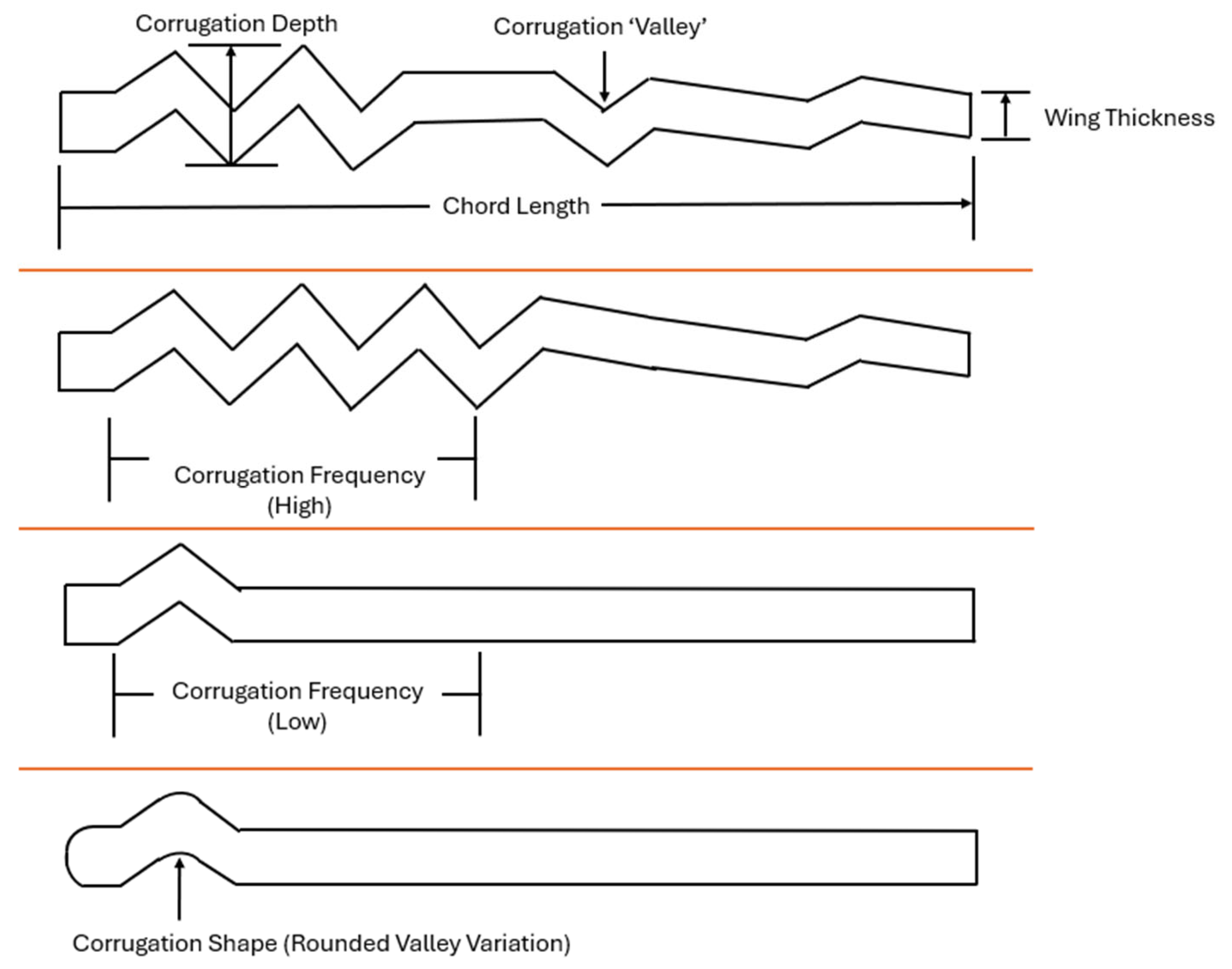
Table 2. Corrugated wing geometrical parameters.
Parameter Metrics and Description
Corrugation Depth The height of the valleys impacts boundary layer control mechanisms.
Corrugation FrequencyThe number of corrugations along the chord affects flow behavior.
Corrugation Shape The edge and peak shapes, from rounded to sharp, influence flow separation and lift.
Material of the Wing Impacts skin friction and boundary layer dynamics.
Wing ThicknessAffects structural integrity and aerodynamic drag.
Wing Configuration Tandem or isolated configurations influence overall aerodynamic efficiency.
Table 3. A list of experimental studies including the study parameters and flow Reynolds number.
Study Parameters and Experimental DescriptionReynolds NumberReferences
Scaled model in a water channel for fluid flow with beam analysis (structural). 450, 800, 900[33,34]
Flight performance of a dragonfly using wind tunnel and high-speed videography. 35,000–60,000[35]
Dragonfly flight (gliding, flapping flight and power requirements) using wind tunnel and high-speed videography. 700–2400[9,36,37]
Comparison between dragonfly wing sections and technical aerofoils using an open-circuit wind tunnel.10,000[1]
Detailed quantitative flow measurements of the flow over a corrugated aerofoil using a low-speed wind tunnel and PIV for MAV applications. 34,000[38]
Similar to [38], but considered a wider range of Reynolds number.58,000–125,000[39]
Developed a method for the 3D reconstruction of a dragonfly wing and tested the fabricated model in a low-speed wind tunnel with PIV.5000, 8000, 12,000[22]
Effects of compressibility on the aerodynamics of a simplified corrugated aerofoil using a “Mars Wind Tunnel” with force measurements, pressure sensitive paint, and schlieren imagery.10,000–25,000[40]
Wind tunnel experiments with MAVs equipped with bio-inspired corrugated and profiled wings, using PIV for flow analysis.80,000–130,000[16]
Table 4. A list of numerical studies including the study parameters and flow Reynolds numbers.
Study Parameters and Numerical MethodologyReynolds NumberReferences
Corrugated wing from [1].
2D—Unsteady (CFD)
500–10,000[5]
Simplified dragonfly aerofoil of Newman’s gliders.
2D—Unsteady (CFD)
2000–8000[44,45]
The interaction between forewing and hindwing in gliding dragonfly flight.
2D—Unsteady (CFD)
300–2000[46]
Corrugated wing from [1].
2D (CFD)—Unsteady and static 3D (FEA)
500–2000[47]
Simplified corrugated wing sections.
3D—Unsteady (CFD)
200–2400[48]
Corrugated wing from [1].
3D—Unsteady (CFD)
1000–10,000[15]
Flapping Tandem wings (aerofoil and flat plate) and corrugated wing form [1].
2D—Unsteady (CFD) and static 3D (FEA)
1000[49]
Reconstruction of the model from [1].
3D—Unsteady (CFD)
1400, 10,000[50]
Two corrugated wings from [1,45].
2D—Unsteady (CFD)
14,000[51]
Corrugated wing form [1] in gliding and flapping phases.
2D—Unsteady (CFD)
200, 4000[2]
Newly designed corrugated structure. 2D—Steady (CFD) and static 3D (FEA)15,632[52]
A realistic dragonfly wing.
2D—Unsteady (CFD)
10,000[53]
Aerofoils with corrugated skin in tandem.
3D—Unsteady (CFD)
120,000[54]
Table 5. Aerodynamic characteristics of wing profiles [1]. For details on 1, 2, and 3 profiles, refer to Figure 3.
Profile Flat PlateAsymmetric Profile 123
C L , 0 0.0220.3900.2700.0530.262
C L , m a x 1.2091.1821.3731.1701.410
Critical AoA+10°+8°+10°+10°+10°
Table 6. Critical AoA for corrugated wing aerodynamics.
Critical AoAMethodReference
CFD[114]
10°Wind Tunnel [40]
10°CFD[2]
Disclaimer/Publisher’s Note: The statements, opinions and data contained in all publications are solely those of the individual author(s) and contributor(s) and not of MDPI and/or the editor(s). MDPI and/or the editor(s) disclaim responsibility for any injury to people or property resulting from any ideas, methods, instructions or products referred to in the content.

