
Preliminary Design of a Tandem-Wing Unmanned Aerial System †

 ,
,  , and
, and
Abstract
:1. Introduction
2. Materials and Methods
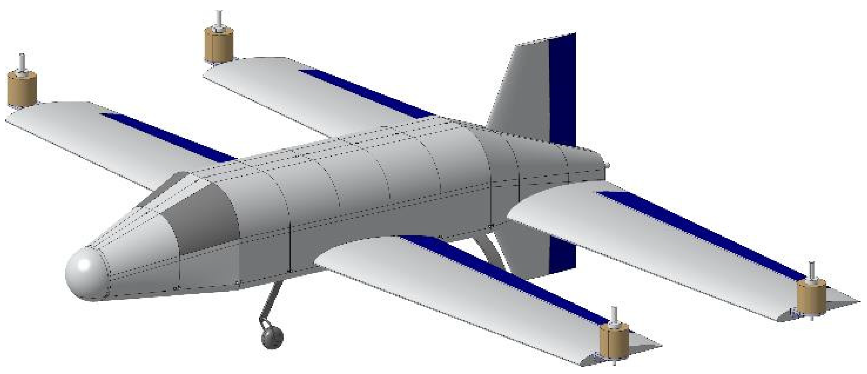
3. Case Study: Tandem-Wing UAS
3.1. Design Requirements
3.2. Fuselage
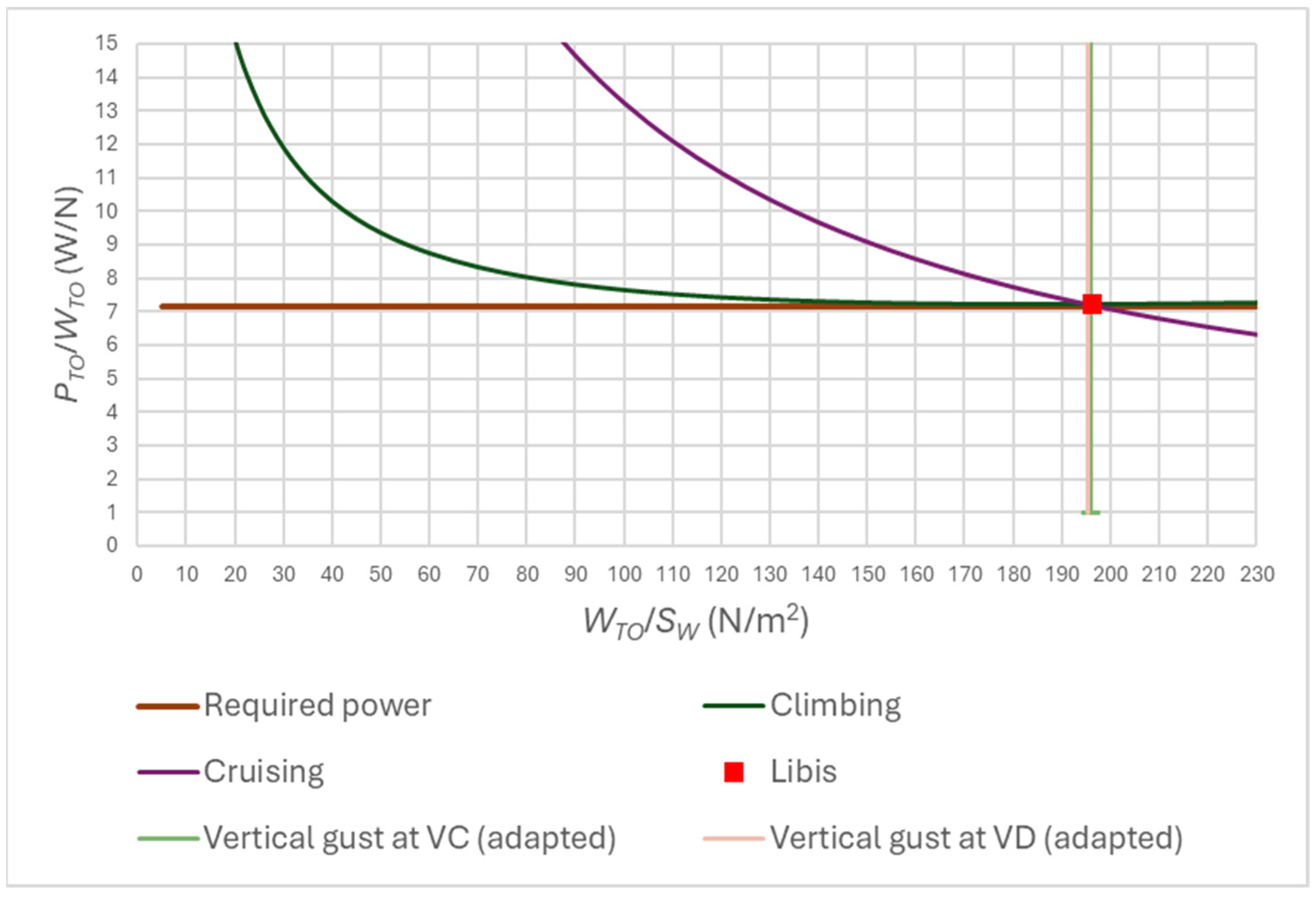
3.3. Design Point and Geometry
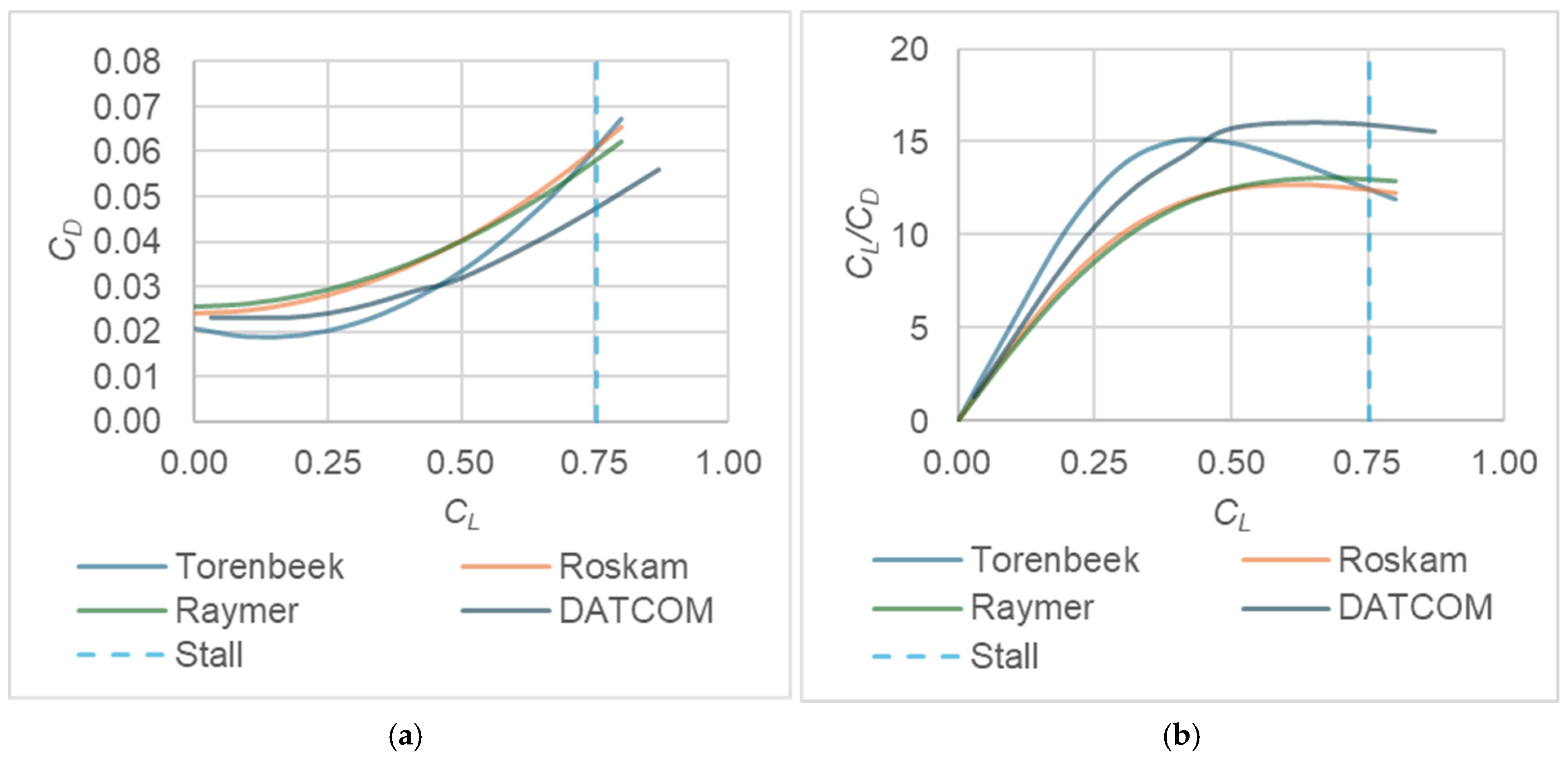
3.4. Aerodynamics
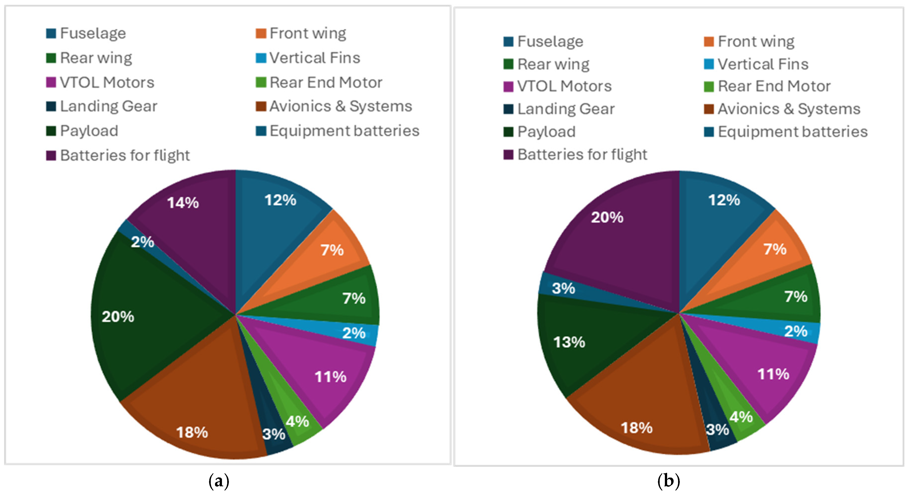
3.5. Weights
3.6. Performance
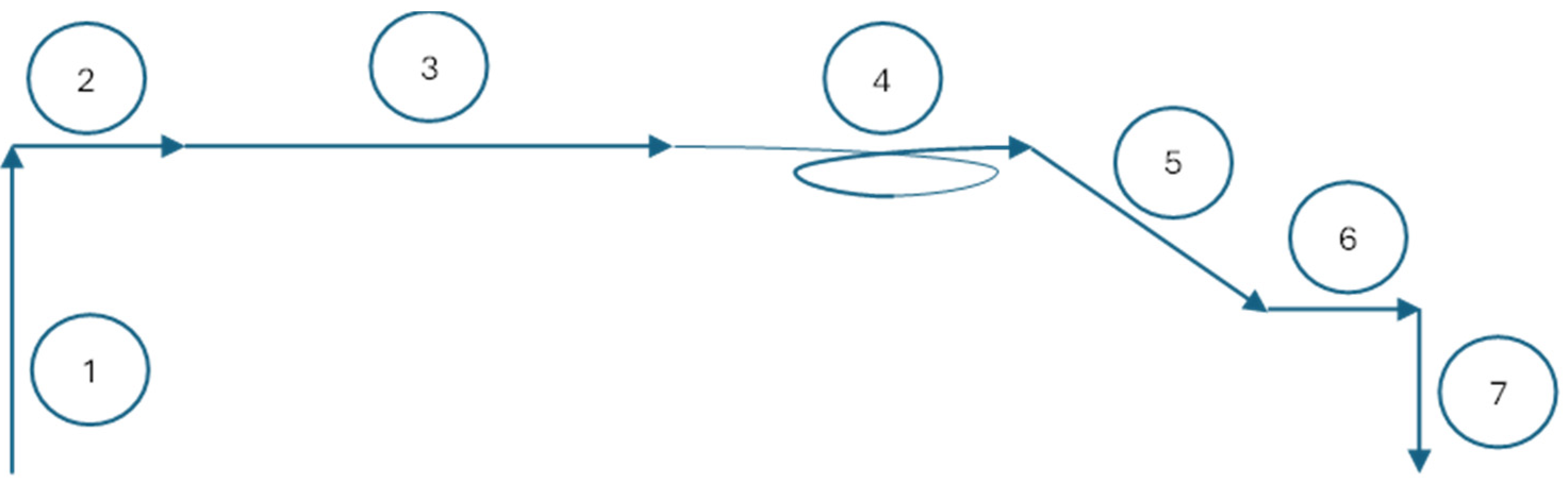
3.6.1. Design Mission
- Takeoff. As a rotary-wing aircraft, takeoff was executed from the ground to 300 feet with full throttle on VTOL motors.
- Acceleration stage. This stage was divided into two sub-stages. First, the weight of the aircraft was lifted by the rotary wing, while the rear motor generated the aircraft’s horizontal speed. During this stage, the angle of attack was kept in the minimum-drag position. This stage ended when the horizontal speed reached the stall speed. From this point, the power transmitted to the VTOL motors was reduced linearly until cruise speed was reached, at which point the VTOL motors were fully turned off. In this second stage, the angle of attack was changed to ensure that enough lift force was provided. At the end of this stage, lift was generated only by the fixed wings. The duration and energy consumption of this phase were carried out using a Runge–Kutta integration method. The horizontal distance traveled at this stage was considered.
- Cruise flight. This was developed at maximum range speed.
- Loiter. The aircraft loitered for 5 min at maximum endurance speed. Because maximum endurance speed and maximum range speed are very close to each other, we decided to fly the UAS at the same speed in both stages.
- Descent stage. Descent was performed at a descent angle of 5º. The constant speed reached at this stage was 32.1 m/s. The descent ended when a height of 33 feet was reached.
- Deceleration stage. The UAS decelerated from 32.1 m/s to 0 m/s. The hypotheses for this stage are like those for the acceleration stage.
- Landing. As a rotary-wing aircraft, the UAS was landed by lowering it from 33 feet to the ground.
3.6.2. Out–Off Design Mission
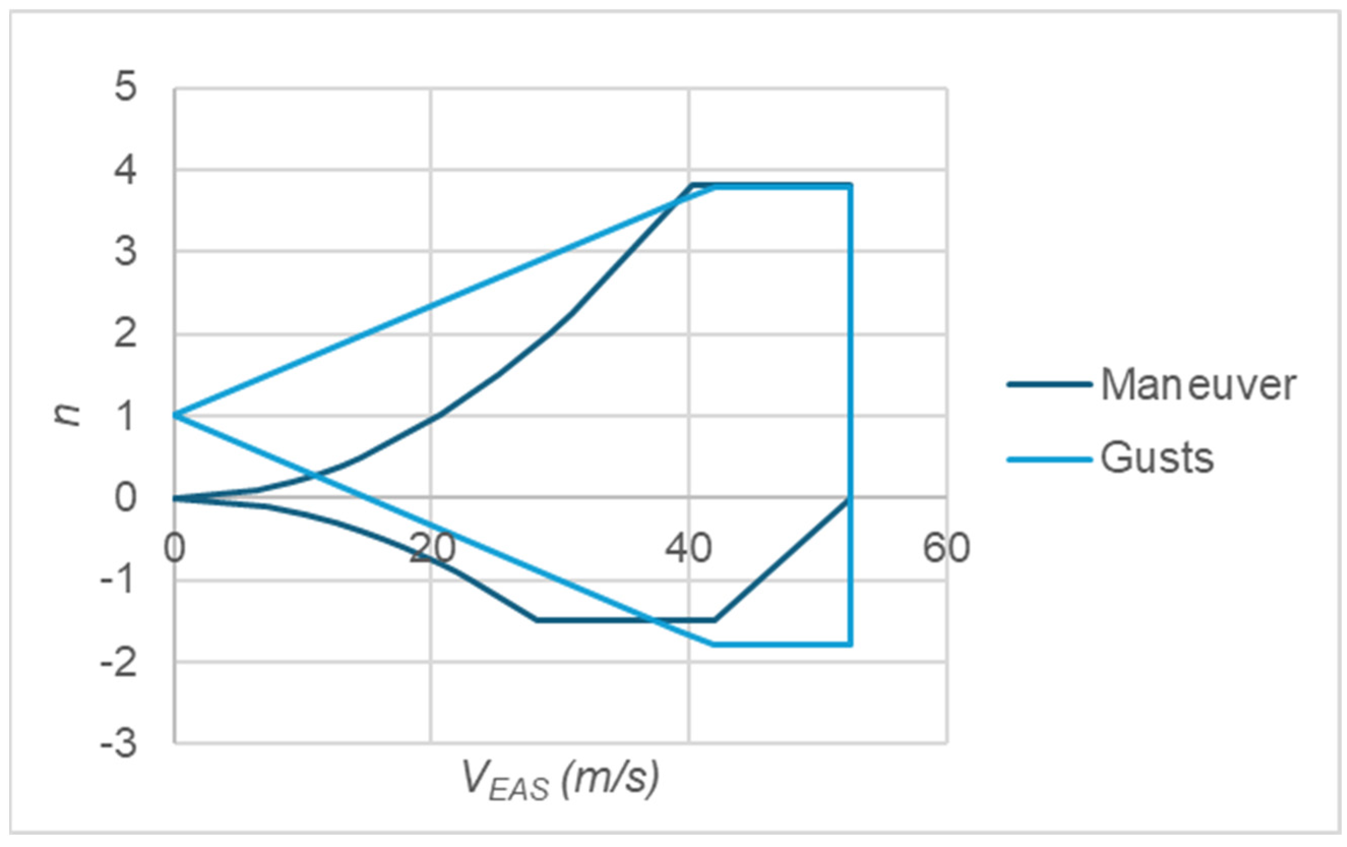
3.6.3. Wind Conditions and Flight Envelope
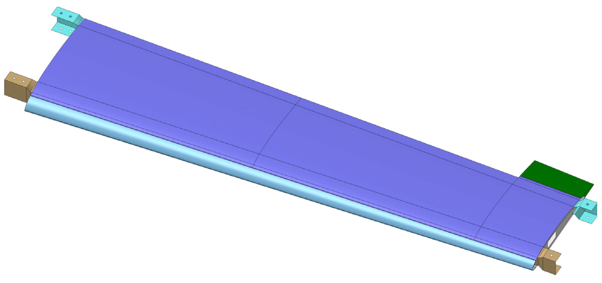
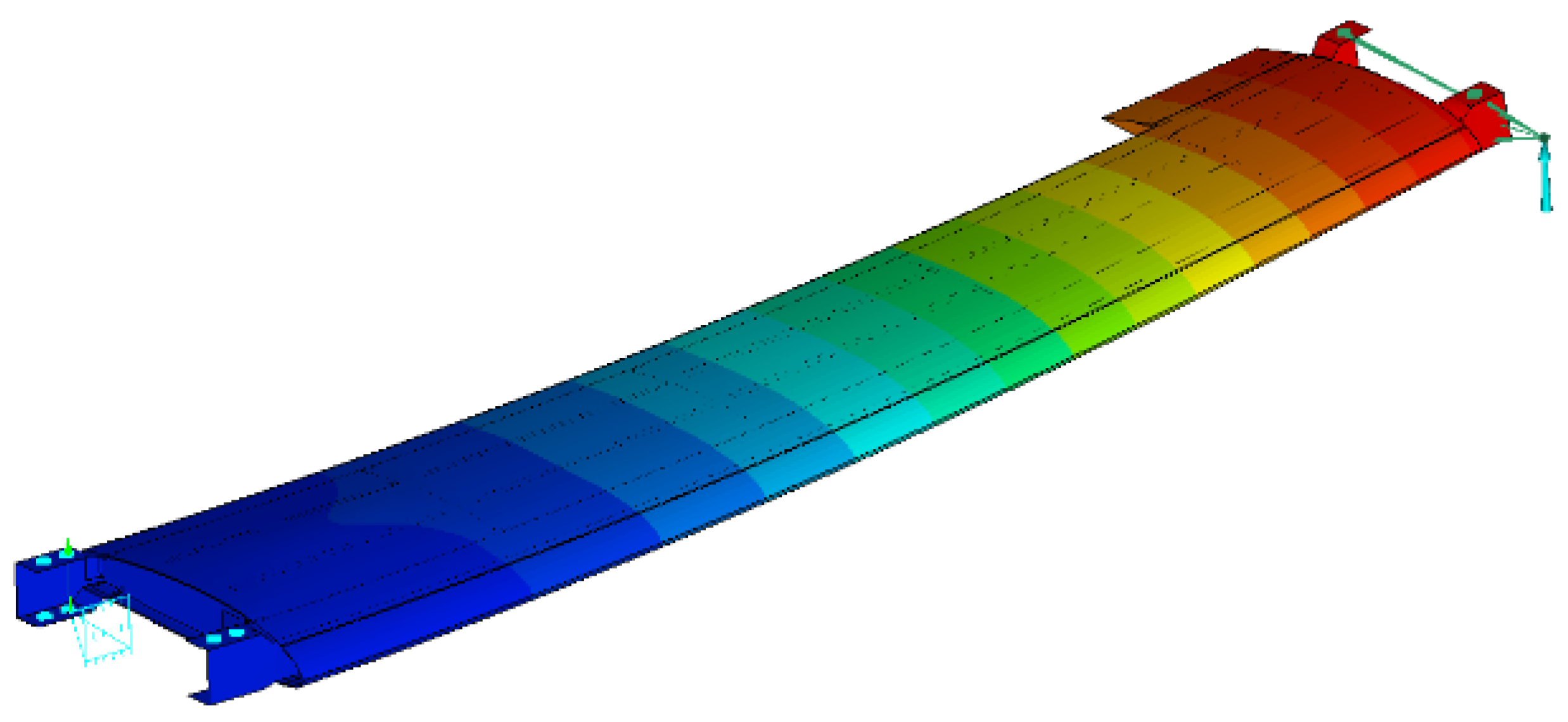
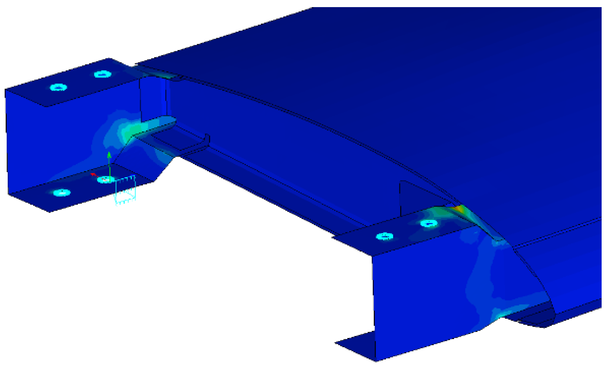
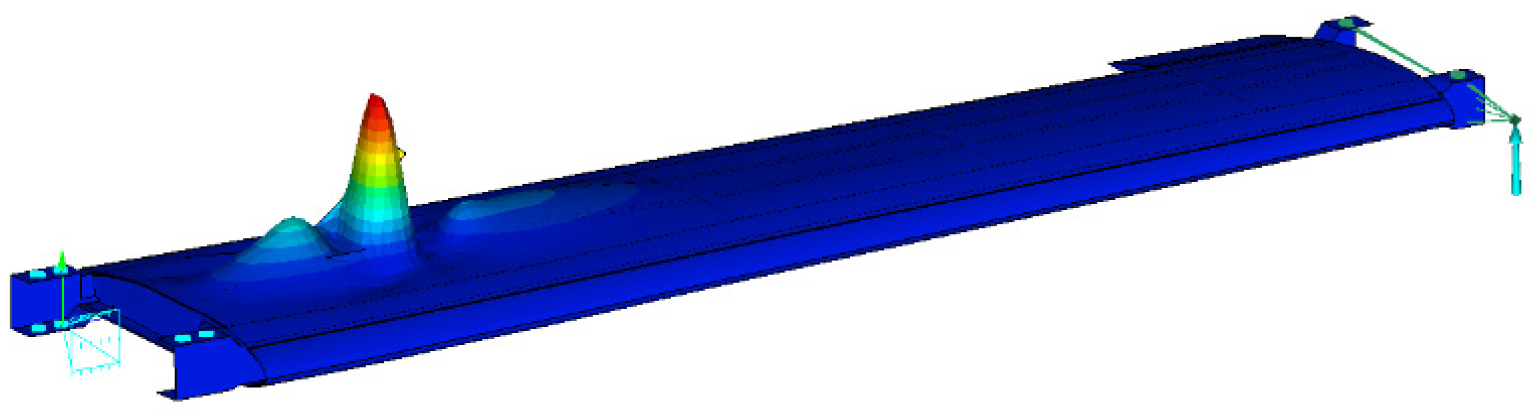
3.7. Structural Concept
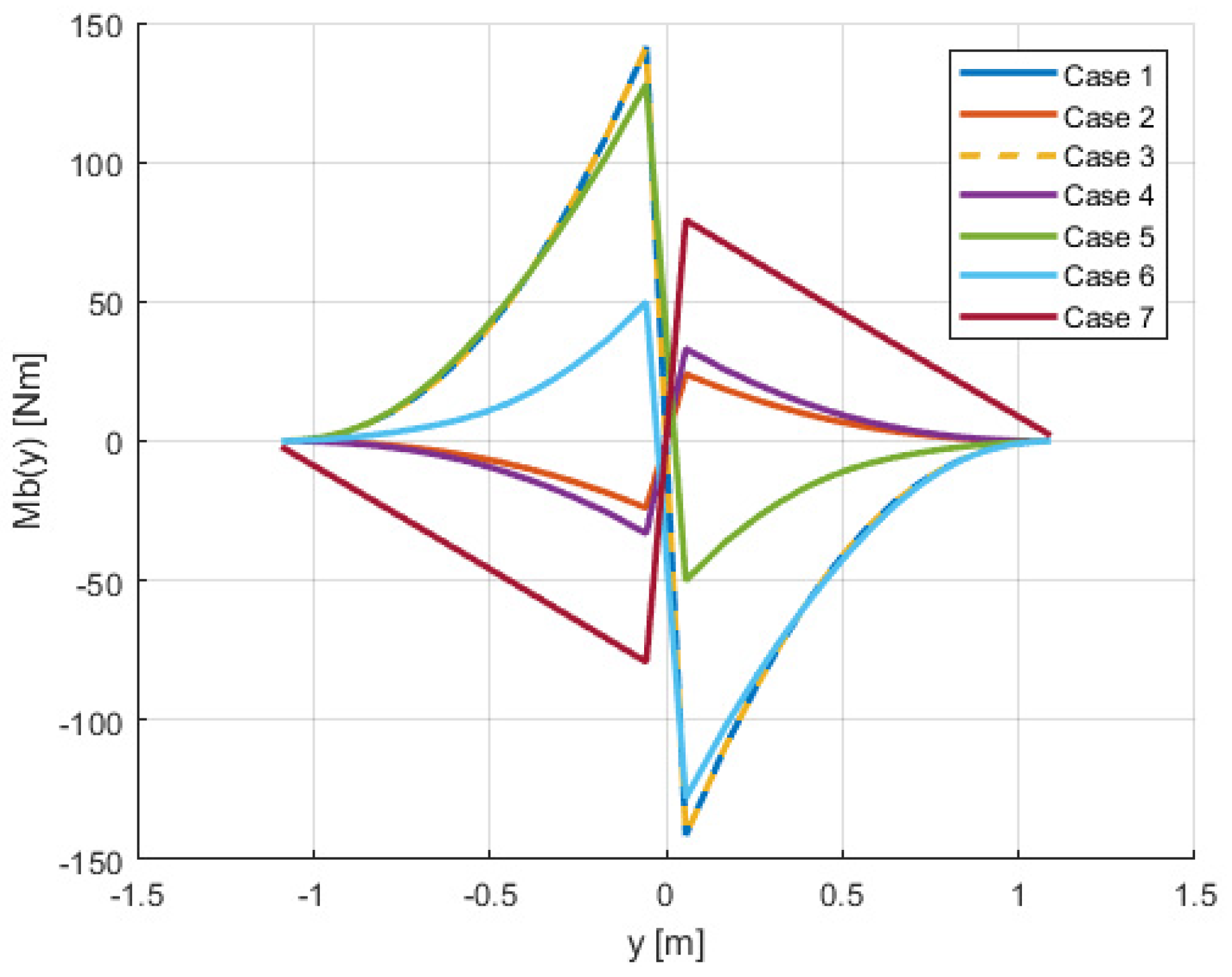
3.7.1. Load Cases
- A symmetric maneuver with the limit positive load factor at cruising speed;
- A symmetric maneuver with the limit negative load factor at cruising speed;
- Vertical gust with a positive load factor at design speed;
- Vertical gust with a negative load factor at design speed;
- An asymmetric maneuver with 2/3 of the limit positive load factor at maneuver design speed, with a steady turn with maximum deflection of the ailerons;
- An Asymmetric maneuver with 2/3 of the limit negative load factor at maneuver design speed, with a steady turn with maximum deflection of the ailerons;
- Axial flight as a quadrotor with a load factor equal to 1.2.
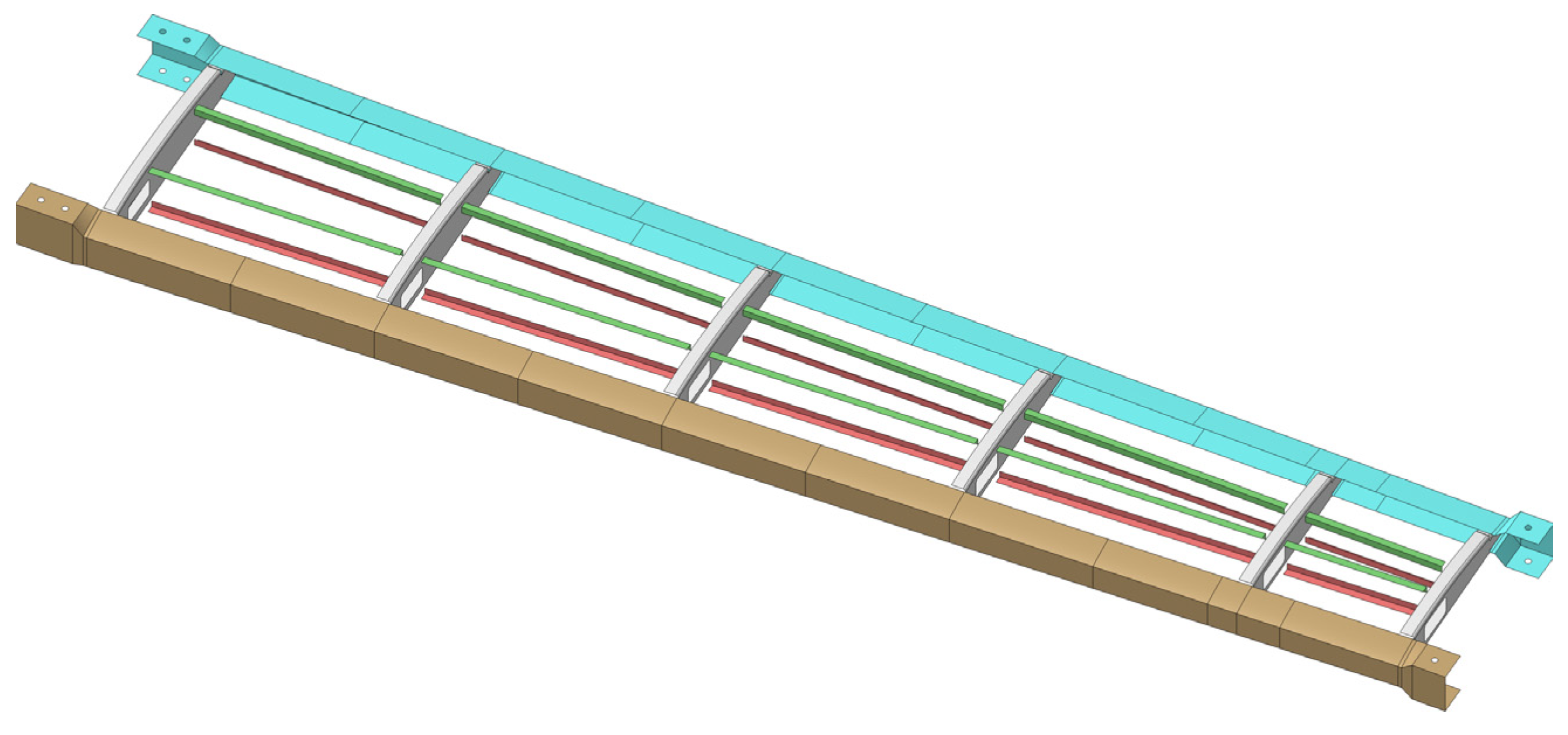
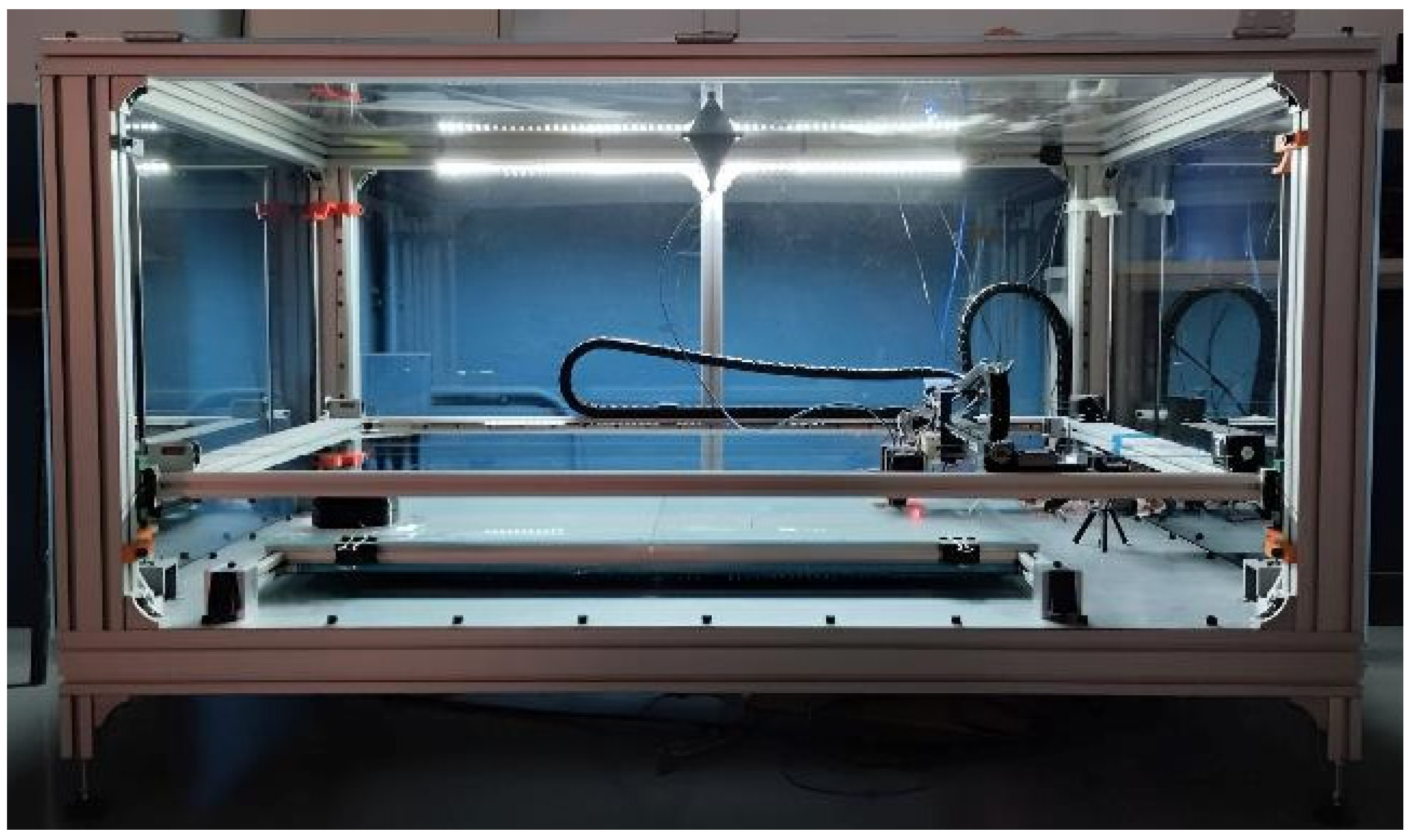
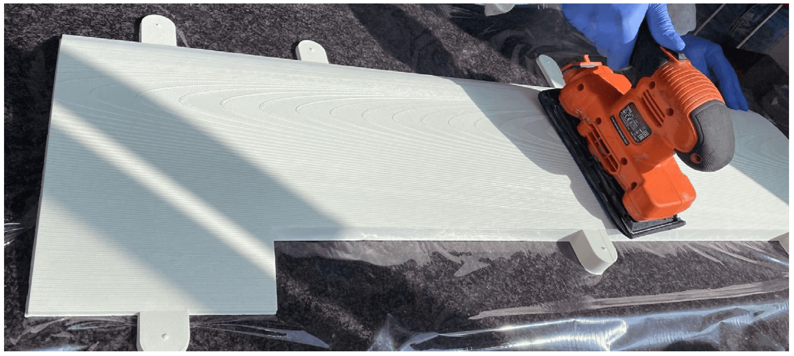
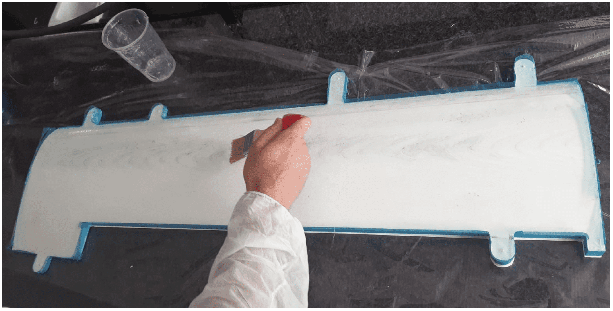
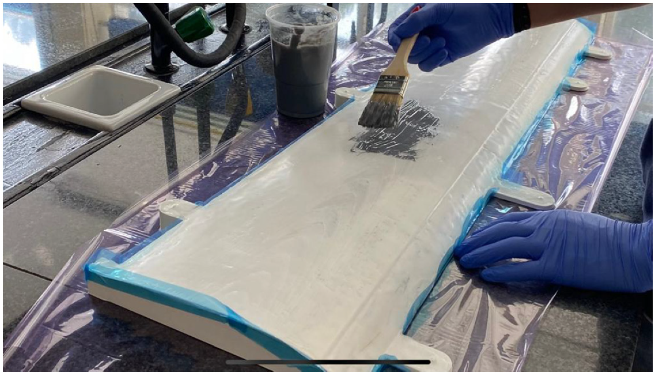
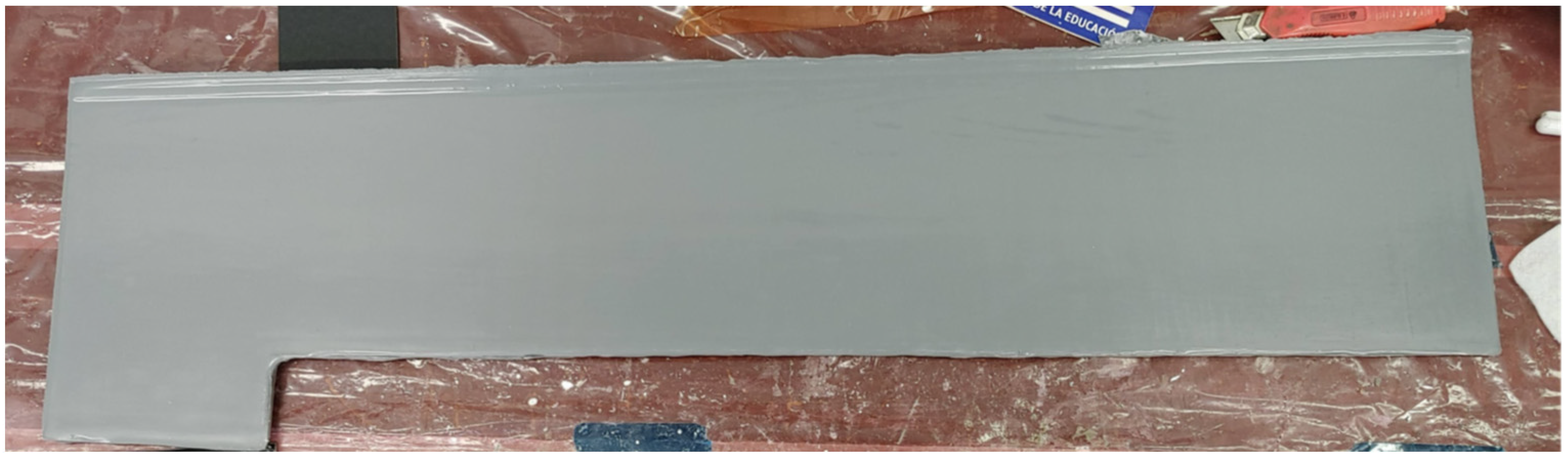
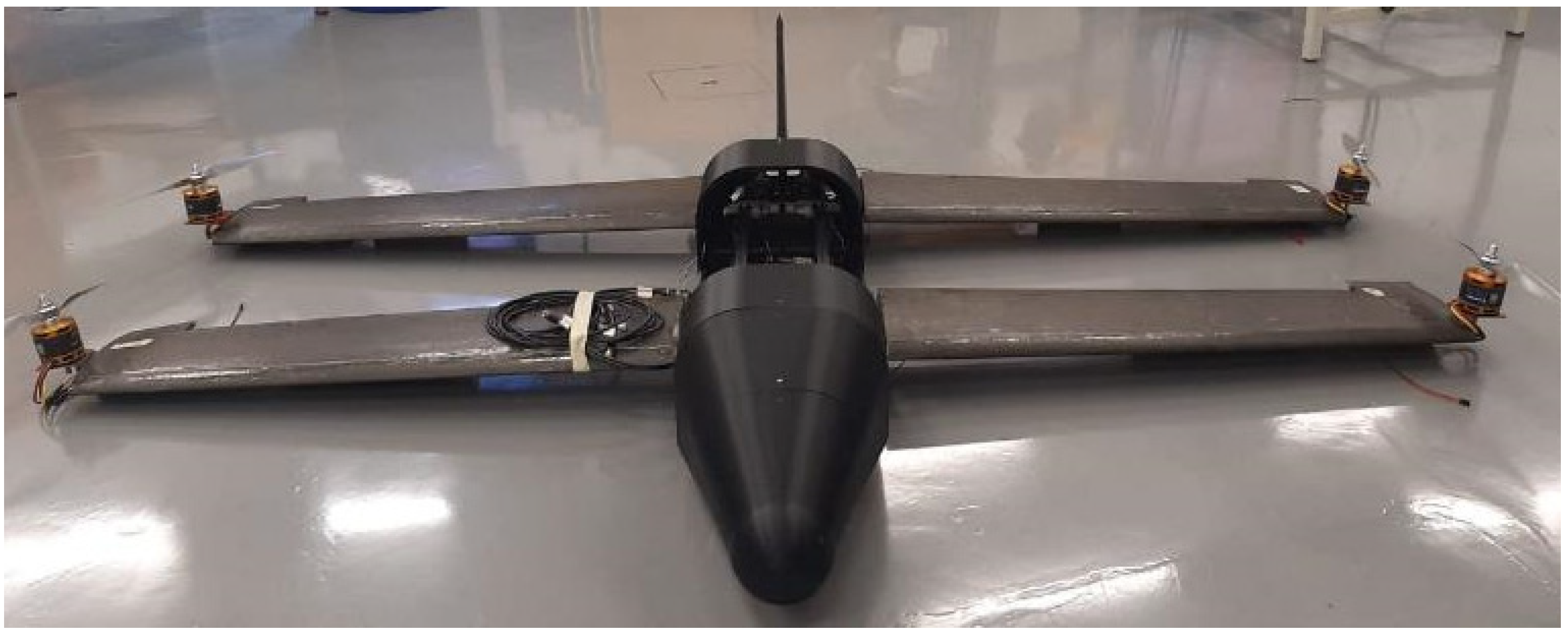
3.7.2. Sizing and Manufacturing
4. Discussion
5. Conclusions
Author Contributions
Funding
Data Availability Statement
Acknowledgments
Conflicts of Interest
References
- Gundlach, J. Civil and Commercial Unmanned Aircraft Systems; AIAA Education Series: Reston, VA, USA, 2016. [Google Scholar]
- Gundlach, J. Designing Unmanned Aircraft Systems: A Comprehensive Approach, 1st ed.; AIAA Educational Series: Reston, VA, USA, 2014. [Google Scholar]
- Austin, R. Unmanned Aircraft Systems; Willey: Hoboken, NJ, USA, 2010. [Google Scholar]
- Gómez-Rodríguez, Á.; Sanchez-Carmona, A.; García-Hernández, L.; Cuerno-Rejado, C. Preliminary Correlations for Remotely Piloted Aircraft Systems Sizing. Aerospace 2018, 5, 5. [Google Scholar] [CrossRef]
- Cuerno-Rejado, C.; García-Hernández, L.; Sánchez-Carmona, A.; Carrio, A.; Sanchez-Lopez, J.L.; Campoy, P. Historical evolution of the unmanned aerial vehicles to the present. Dyna 2016, 91, 282–288. [Google Scholar]
- Elmeseiry, N.; Alshaer, N.; Ismail, T. A Detailed Survey and Future Directions of Unmanned Aerial Vehicles (UAVs) with Potential Applications. Aerospace 2021, 8, 363. [Google Scholar] [CrossRef]
- Goraj, Z. Design challenges associated with development of a new generation UAV. Aircr. Eng. Aerosp. Technol. 2005, 77, 361–368. [Google Scholar] [CrossRef]
- EASA Drones & Air Mobility. Available online: https://www.easa.europa.eu/en/domains/civil-drones (accessed on 27 February 2025).
- FAA Drones. Available online: https://www.faa.gov/uas (accessed on 27 February 2025).
- Panagiotou, P.; Kaparos, P.; Salpingidou, C.; Yakinthos, K. Aerodynamic design of a MALE UAV. Aerosp. Sci. Technol. 2016, 50, 127–138. [Google Scholar] [CrossRef]
- Kontogiannis, S.G.; Ekaterinaris, J.A. Design, performance evaluation and optimization of a UAV. Aerosp. Sci. Technol. 2013, 29, 339–350. [Google Scholar] [CrossRef]
- Bravo-Mosquera, P.D.; Botero-Bolivar, L.; Acevedo-Giraldo, D.; Cerón-Muñoz, H.D. Aerodynamic design analysis of a UAV for superficial research of volcanic environments. Aerosp. Sci. Technol. 2017, 70, 600–614. [Google Scholar] [CrossRef]
- Goetzendorf-Grabowski, T.; Rodzewicz, M. Design of UAV for photogrammetric mission in Antarctic area. Proc. Inst. Mech. Eng. Part G J. Aerosp. Eng. 2017, 231, 1660–1675. [Google Scholar] [CrossRef]
- Panagiotou, P.; Fotiadis-Karras, S.; Yakinthos, K. Conceptual design of a Blended Wing Body MALE UAV. Aerosp. Sci. Technol. 2018, 73, 32–47. [Google Scholar] [CrossRef]
- Cipolla, V.; Dine, A.; Viti, A.; Binante, V. MDAO and Aeroelastic Analyses of Small Solar-Powered UAVs with Box-Wing and Tandem-Wing Architectures. Aerospace 2023, 10, 105. [Google Scholar] [CrossRef]
- Zhao, X.; Zhou, Z.; Zhu, X.; Guo, A. Design of a Hand-Launched Solar-Powered Unmanned Aerial Vehicle (UAV) System for Plateau. Appl. Sci. 2020, 10, 1300. [Google Scholar] [CrossRef]
- An, J.H.; Kwon, D.Y.; Jeon, K.S.; Tyan, M.; Lee, J.W. Advanced Sizing Methodology for a Multi-Mode eVTOL UAV Powered by a Hydrogen Fuel Cell and Battery. Aerospace 2022, 9, 71. [Google Scholar] [CrossRef]
- Suewatanakul, S.; Porcarelli, A.; Olsson, A.; Grimler, H.; Chiche, A.; Mariani, R.; Lindbergh, G. Conceptual Design of a Hybrid Hydrogen Fuel Cell/Battery Blended-Wing-Body Unmanned Aerial Vehicle—An Overview. Aerospace 2022, 9, 275. [Google Scholar] [CrossRef]
- Bishay, P.L.; Kok, J.S.; Ferrusquilla, L.J.; Espinoza, B.M.; Heness, A.; Buendia, A.; Zadoorian, S.; Lacson, P.; Ortiz, J.D.; Basilio, R.; et al. Design and Analysis of MataMorph-3: A Fully Morphing UAV with Camber-Morphing Wings and Tail Stabilizers. Aerospace 2022, 9, 382. [Google Scholar] [CrossRef]
- Airbus Cargo Drone Challenge. Available online: https://www.airbus.com/en/newsroom/press-releases/2016-07-airbus-group-and-local-motors-name-winners-of-next-generation (accessed on 11 March 2025).
- Torenbeek, E. Synthesis of Subsonic Airplane Design; Delft University Press: Delft, The Netherlands; Kluwer Academic Publishers: Dordrecht, The Netherlands, 1982. [Google Scholar]
- Roskam, J. Airplane Design, Part I: Preliminary Sizing of Airplanes; Roskam Aviation and Engineering Corporation: Ottawa, KS, USA, 1985. [Google Scholar]
- Roskam, J. Airplane Design, Part II: Preliminary Configuration Design and Integration of the Propulsion System, 1st ed.; Roskam Aviation and Engineering Corporation: Ottawa, KS, USA, 1989. [Google Scholar]
- Roskam, J. Airplane Design, Part III: Layout Design of Cockpit, Fuselage, Wing and Empennage: Cutaways and Inboard Profiles; Roskam Aviation and Engineering Corporation: Ottawa, KS, USA, 1986. [Google Scholar]
- Roskam, J. Airplane Design, Part IV: Layout Design of Landing Gear and Systems; Roskam Aviation and Engineering Corporation: Ottawa, KS, USA, 1986. [Google Scholar]
- Roskam, J. Airplane Deisgn. Part V: Component Weight Estimation; DAR Corporation: Ottawa, KS, USA, 1999; ISBN 1884885500. [Google Scholar]
- Roskam, J. Airplane Design, Part VI: Preliminary Calculation of Aerodynamic, Thrust and Power Characteristics; Roskam Aviation and Engineering Corporation: Ottawa, KS, USA, 1987. [Google Scholar]
- Roskam, J. Airplane Design, Part VII: Determination of Stability, Control and Performance Characteristics: FAR and Military Requirements; Roskam Aviation and Engineering Corporation: Ottawa, KS, USA, 1988. [Google Scholar]
- Roskam, J. Airplane Deisgn, Part VIII: Airplane Cost Estimation: Design, Development, Manufacturing And operating; Roskam Aviation and Engineering Corporation: Ottawa, KS, USA, 1985. [Google Scholar]
- Raymer, D.P. Aircraft design: A Conceptual Approach, 4th ed.; AIAA: Reston, VA, USA, 2006. [Google Scholar]
- NATO. STANAG 4703/AEP-83 Light Unmanned Aircraft; Edition B Version 1; Nato Standardization Agency: Brussels, Belgium, 2016. [Google Scholar]
- Torenbeek, E. Advanced Aircraft Design; John Wiley & Sons, Ltd.: Chichester, UK, 2013. [Google Scholar]
- Cuerno-Rejado, C.; García-Hernández, L.; Sanchez-Carmona, A.; Fernández-López, A.; Pintado-Sanjuanbenito, J.M. Diseño Modular de un Rpas de ala Tándem de Despegue Vertical. In Proceedings of the CivilDRON’17, Fundación de la Energía de la Comunidad de Madrid, Madrid, Spain, 25–26 January 2017. [Google Scholar]
- Nicolai, L.M.; Carichner, G.E. Fundamentals of Aircraft and Airship Design; AIAA Education Series: Reston, VA, USA, 2020; Volume I-Aircraft Design, ISBN 9789896540821. [Google Scholar]
- Pratt, K.G. A Revised Formula for Calculation of Gust Loads; NACA-TN-2964; NACA: Boston, MA, USA, 1953. [Google Scholar]
- Roskam, J. Airplane Flight Dynamics and Automatic Flight Controls. Part I and II; Roskam Aviation and Engineering Corporation, USA: Ottawa, KS, USA, 1982. [Google Scholar]
- Finck, R.D. USAF Stability and Control DATCOM. Flight Dyn. Labaratory 1978, 18, 3200. [Google Scholar]
- Kheit, E. Software Development and Validation for Subsonic and Transonic Aircraft Class 2 Drag Polar Determination. In Proceedings of the 18th International Congress of Mechanical Engineering, Ouro Preto, MG, Brazil, 6–11 November 2005. [Google Scholar]
- Roskam, J. Methods for Estimating Stability and Control Derivatives of Conventional Subsonic Airplanes, 4th ed.; Roskam Aviation and Engineering Corporation: Ottawa, KS, USA, 1983. [Google Scholar]
- Drela, M. AVL (Athena Vortex Lattice). Available online: https://web.mit.edu/drela/Public/web/avl/ (accessed on 6 April 2025).
- APC. Propeller Performance Data. Available online: https://www.apcprop.com/technical-information/performance-data/ (accessed on 4 March 2025).
- AXi Model Motors. Available online: https://www.modelmotors.cz/product/motors/ (accessed on 4 March 2025).
- e-calc. Available online: https://www.ecalc.ch/ (accessed on 4 March 2025).
- Melin, T. A Vortex Lattice MATLAB Implementation for Linear Aerodynamic Wing Applications. Master’s Thesis, Royal Institute of Technology (KTH), Stockholm, Sweden, 2000. [Google Scholar]
- Easycomposites. XCRTM Epoxy Coating Resin—Technical Datasheet 2024. Available online: https://media.easycomposites.co.uk/datasheets/EC-TDS-XCR-Epoxy-Coating-Resin.pdf (accessed on 13 April 2025).
- Easycomposites. EG160 High Temp Epoxy Tooling Gelcoat—Technical Datasheet 2023. Available online: https://media.easycomposites.co.uk/datasheets/EG160-High-Temp-Epoxy-Tooling-Gelcoat-v2.pdf (accessed on 13 April 2025).
- Esaycomposites. EMP160 High Temperature Moulding Paste—Technical Datasheet 2024. Available online: https://media.easycomposites.eu/datasheets/EC-TDS-EMP160-High-Temp-Moulding-Paste.pdf (accessed on 13 April 2025).


| Length [mm] | Width [mm] | Height [mm] | |
|---|---|---|---|
| Flight control computer | 170 | 180 | 80 |
| Internal measurement unit | 100 | 30 | 40 |
| ADS-B transponder | 89 | 46 | 18 |
| Antennas and externally mounted systems | - | - | - |
| Flight termination parachute | 280 | 120 | 50 |
| Flight termination system | 200 | 55 | 55 |
| Camera | 97 | 95 | 97 |
| Communication system | 57 | 98 | 86 |
| Payload | 473 | 368 | 210 |
| Induction system charger | 174 | 94 | 43 |
| Induction system coil | 300 | 300 | 10 |
| Length | |
|---|---|
| Length | 2.00 m |
| “Cylindrical zone” length | 1.00 m |
| Nose length | 0.50 m |
| Rear end length | 0.50 m |
| Maximum width | 0.42 m |
| Maximum height | 0.33 m |
| Phase | Duration [min] | Energy Consumption [Wh] | Horizontal Speed [m/s] | Vertical Speed [m/s] | |
|---|---|---|---|---|---|
| 1 | Takeoff | 0.76 | 54.32 | 0 | 2.5 |
| 2 | Acceleration | 0.13 | 9.86 | 0–23.11 | 0 |
| 3 | Cruise | 45.6/73.2 | 489/798 | 23.11 | 0 |
| 4 | Loiter | 5 | 37.25 | 23.11 | 0 |
| 5 | Decent | 0.48 | 1.76 | 31.98 | −2.8 |
| 6 | Deceleration | 0.19 | 7.12 | 32.1–0 | 0 |
| 7 | Landing | 0.08 | 5.89 | 0 | −2 |
Disclaimer/Publisher’s Note: The statements, opinions and data contained in all publications are solely those of the individual author(s) and contributor(s) and not of MDPI and/or the editor(s). MDPI and/or the editor(s) disclaim responsibility for any injury to people or property resulting from any ideas, methods, instructions or products referred to in the content. |
© 2025 by the authors. Licensee MDPI, Basel, Switzerland. This article is an open access article distributed under the terms and conditions of the Creative Commons Attribution (CC BY) license (https://creativecommons.org/licenses/by/4.0/).
Share and Cite
Sanchez-Carmona, A.; del Río Velilla, D.; Fernández López, A.; Cuerno-Rejado, C. Preliminary Design of a Tandem-Wing Unmanned Aerial System. Aerospace 2025, 12, 363. https://doi.org/10.3390/aerospace12050363
Sanchez-Carmona A, del Río Velilla D, Fernández López A, Cuerno-Rejado C. Preliminary Design of a Tandem-Wing Unmanned Aerial System. Aerospace. 2025; 12(5):363. https://doi.org/10.3390/aerospace12050363
Chicago/Turabian StyleSanchez-Carmona, Alejandro, Daniel del Río Velilla, Antonio Fernández López, and Cristina Cuerno-Rejado. 2025. "Preliminary Design of a Tandem-Wing Unmanned Aerial System" Aerospace 12, no. 5: 363. https://doi.org/10.3390/aerospace12050363
APA StyleSanchez-Carmona, A., del Río Velilla, D., Fernández López, A., & Cuerno-Rejado, C. (2025). Preliminary Design of a Tandem-Wing Unmanned Aerial System. Aerospace, 12(5), 363. https://doi.org/10.3390/aerospace12050363