3.1. Interaction of the Bounded Combined Filament with the Supersonic Blunt Cylinder
Consider the interaction of the bounded combined filament with the supersonic cylinder shock layer in the case of α
ρ1 < α
ρ. This means that the temperature of the gas in the internal part of the filament is greater than in the external one. The dynamics of density are presented in
Figure 2a,b (Δ
l = 4
D, dimensionless time moments are indicated), and below in
Section 3.1 and
Section 3.2 ti = 13.01. Two density stratified vortices caused by the Richtmyer–Meshkov instabilities are seen to be formed in front of the body. The density stratified structure of these vortices is caused by the rolling contact discontinuities (boundaries of the energy source) under the accelerating effect of the bow shock wave [
5]. Gas inside these vortices is rotating clockwise. The corresponding pressure fields demonstrate the presence of two points of local minima (at the centers of these vortexes) and the complicated lambda-waves configuration which arises above the vortices. Also, the piece-wise linear fracture of the bow shock wave front is forming (
Figure 2c,d).
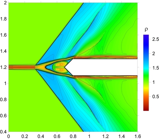
The dynamics of the density field in the case of α
ρ1 > α
ρ when the temperature of the gas in the internal part of the filament is smaller than in the external one is presented in
Figure 3a,b. Two vortices accompanying the Richtmyer–Meshkov instabilities are seen. The upper vortex is rotating clockwise; the lower vortex is rotating counterclockwise. The according pressure fields are presented in
Figure 3c,d. The vortex structure causes the reduction of the frontal drag force, too, but to a lesser degree than in the previous case.
Figure 4 demonstrates the face drag force dynamics for different α
ρ1. Here, the drag force is normalized by its value in the absence of energy deposition
F0. It is seen that, the higher density in the internal filament, the smaller the drop in the drag force that is obtained. For α
ρ1 < α
ρ the second vortex from the internal part enhances the effect from the first one and as a result the drag force drop is also increased.
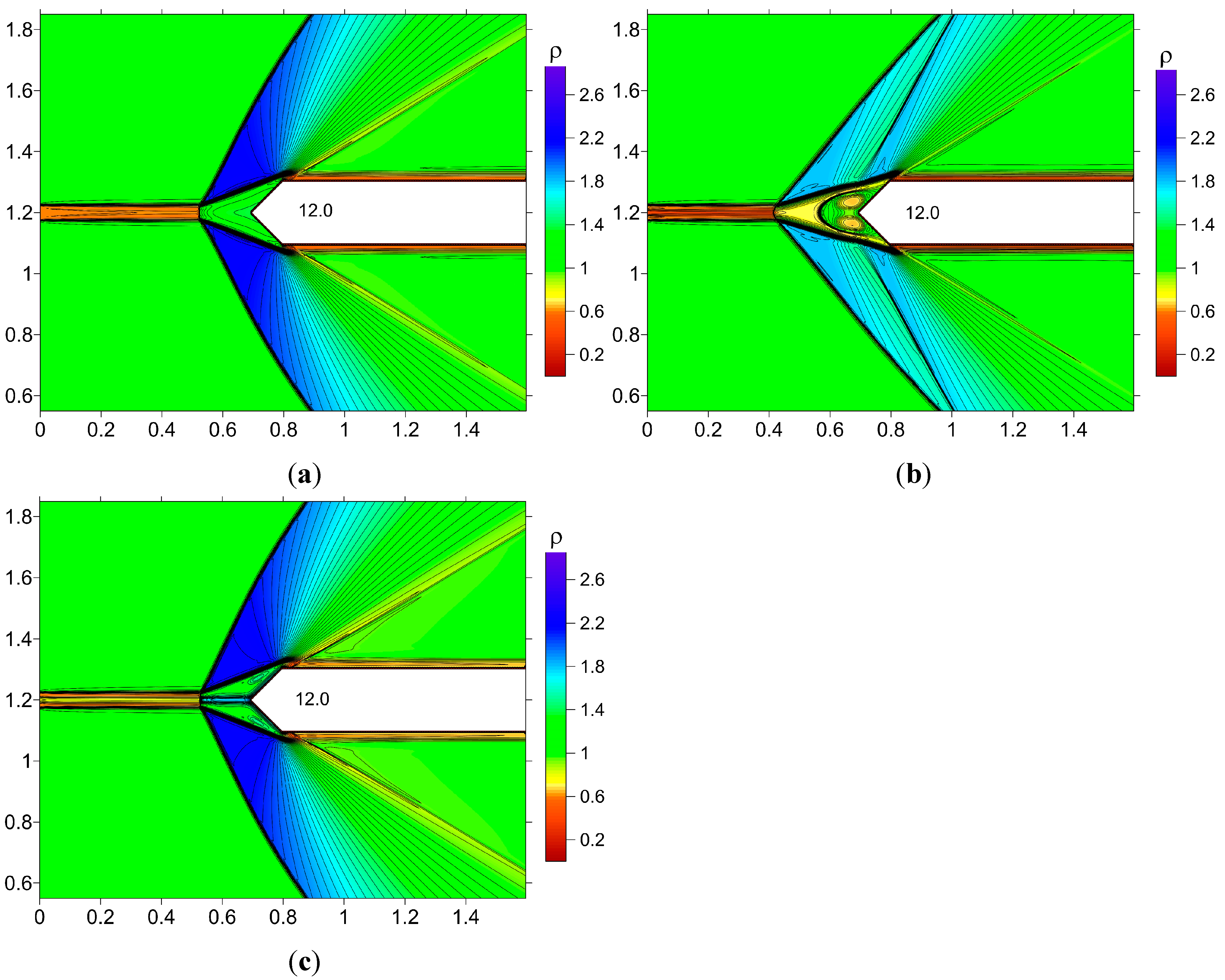
Figure 2.
Generation of two vortices rotating clockwise as the result of the Richtmyer–Meshkov instabilities, d/D = 0.25, d1/D = 0.075, αρ = 0.5, αρ1 = 0.35: (a,b) Density fields; (c,d) Pressure fields.
Figure 2.
Generation of two vortices rotating clockwise as the result of the Richtmyer–Meshkov instabilities, d/D = 0.25, d1/D = 0.075, αρ = 0.5, αρ1 = 0.35: (a,b) Density fields; (c,d) Pressure fields.
Figure 3.
Generation of two vortices rotating in opposite directions as the result of the Richtmyer–Meshkov instabilities, d/D = 0.25, d1/D = 0.075, αρ = 0.5, αρ1 = 0.75: (a,b) Density fields; (c,d) Pressure fields.
Figure 3.
Generation of two vortices rotating in opposite directions as the result of the Richtmyer–Meshkov instabilities, d/D = 0.25, d1/D = 0.075, αρ = 0.5, αρ1 = 0.75: (a,b) Density fields; (c,d) Pressure fields.
Figure 4.
Dynamics of frontal drag force for non-combined and combined filaments for d/D = 0.25, Δl/D = 4, αρ = 0.5 and different values of αρ1 and d1/D.
Figure 4.
Dynamics of frontal drag force for non-combined and combined filaments for d/D = 0.25, Δl/D = 4, αρ = 0.5 and different values of αρ1 and d1/D.
For αρ1 > αρ the second vortex weakens the first one and the opposite effect is seen in the drag force dynamics. Also, it shows that the results are weakly dependent on the value of d1 (for two filaments with different d1 the face drag force dynamics are quite similar—curves 2 and 3).
In
Table 2 the drag force characteristics for the different parameters of the filaments are presented. For α
ρ = 0.5 and α
ρ1 = 0.35 the combining energy sources effect on drag force reduction of 18.8% (related to the non-combined filament) occurs.
Table 2.
Blunt cylinder, M = 1.89.
Table 2.
Blunt cylinder, M = 1.89.
| Type of Filament | (F0 − Fmin)/F0 (%) |
|---|
| Non-combined, d/D = 0.25, αρ = 0.5 | 74.4 |
| Combined, d/D = 0.25, d1/D = 0.125, αρ = 0.5, αρ1 = 0.35 | 88.4 |
| Combined, d/D = 0.25, d1/D = 0.075, αρ = 0.5, αρ1 = 0.35 | 86.9 |
| Combined, d/D = 0.25, d1/D = 0.075, αρ = 0.5, αρ1 = 0.65 | 63.6 |
| Combined, d/D = 0.25, d1/D = 0.075, αρ = 0.5, αρ1 = 0.85 | 55.0 |
3.2. Interaction of the Infinite Combined Filament with the Supersonic Blunt Cylinder
The effect of the infinite combined filament on the supersonic shock layer is examined. The interaction of the body’s face with the vortex structure is accompanied by the drag force reduction, the drop in the drag force being practically the same as in the case of the bounded energy release. The simulations show that the introduction of the internal part into the filament causes the qualitative reconstruction of the flow (
Figure 5). For α
ρ1 < α
ρ introduction of the internal part stabilizes the flow suppressing the shear layer Kelvin–Helmholtz instability (or decreasing the scale of the vortices).
Figure 5a shows the line of vortices accompanying this instability in the case of non-combined (homogeneous) filament. In
Figure 5b the suppression of this instability is seen for the external part of the combined filament, this instability being produced only by the internal part of the filament. For α
ρ1 > α
ρ the suppression does not take place; the lines of vortices are generating from the external part of the filament. Also, one can see two heated layers arising in front of the body (
t = 15.2) the layer neighboring to the axis is colder than the surrounding one. So in this case forming the combined filament favors the transport of the heated gas to the body’s surface.
Figure 5.
Density contours, M = 1.89, αρ = 0.5: (a) Non-combined filament; (b) Combined filament, αρ1 = 0.4; (c) Combined filament, αρ1 = 0.75.
Figure 5.
Density contours, M = 1.89, αρ = 0.5: (a) Non-combined filament; (b) Combined filament, αρ1 = 0.4; (c) Combined filament, αρ1 = 0.75.
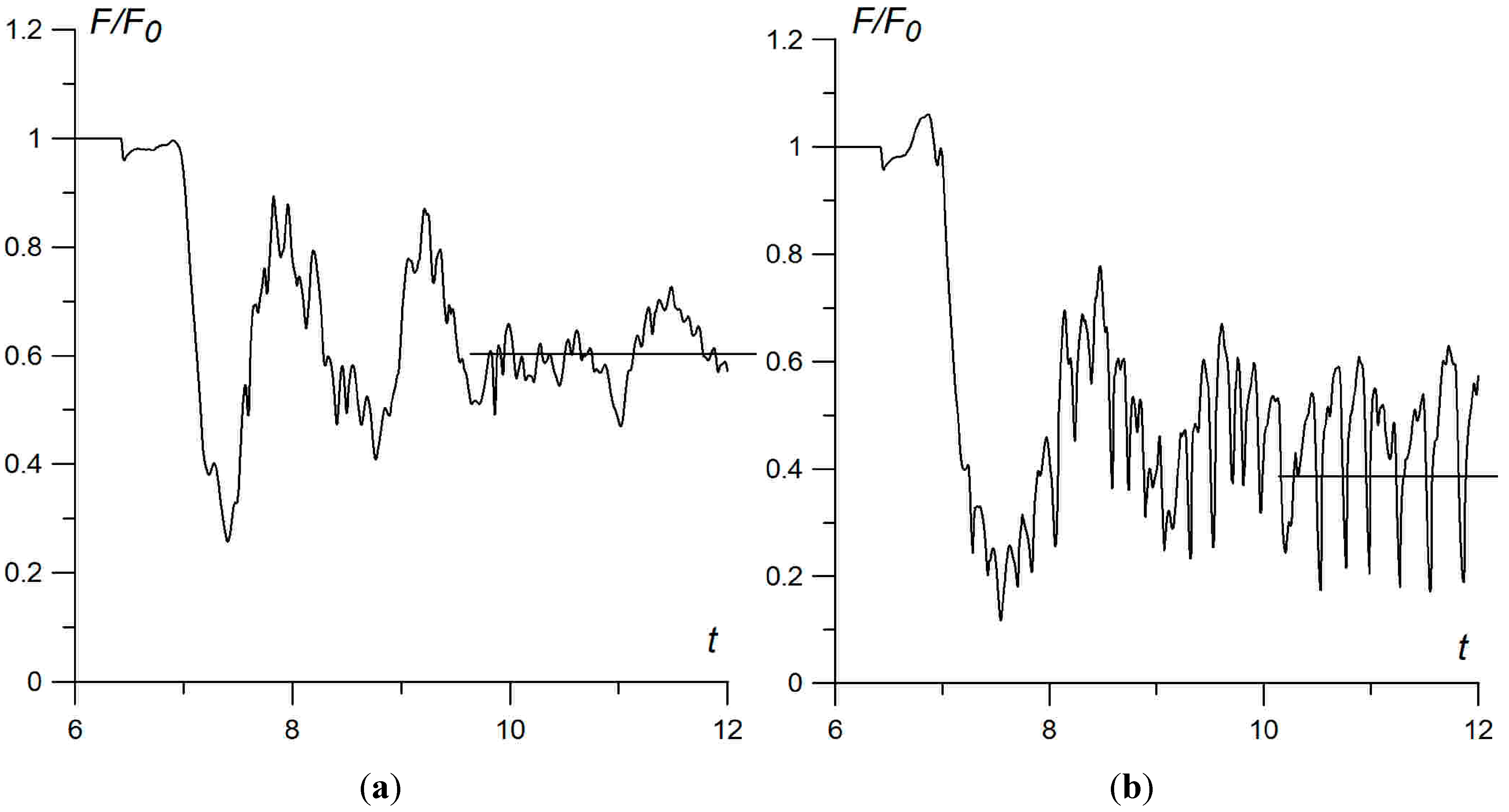
In addition, the most important effect of the combined energy release is the suppression of the large scaled pulsations which are inherent to the flows produced by the homogeneous (non-combined) energy sources. The pulsating flow mode is established for the considered flow parameters in [
5,
7]. Compare the frontal drag force dynamics in the case of the non-combined filament (
Figure 6a) and produced by the same external filament with the introduced internal parts (
Figure 6b,c). It can be pointed out that the combined energy deposition favors the suppression of the large scaled flow pulsations via predominance of the small scaled fluctuations. Also, it is seen that the mean values of the drag force in the statistically steady state are smaller for smaller α
ρ1.
Figure 6.
Dynamics of dimensionless frontal drag force, M = 1.89, αρ = 0.5: (a) Non-combined filament; (b) Combined filament, αρ1 = 0.4; (c) Combined filament, αρ1 = 0.75.
Figure 6.
Dynamics of dimensionless frontal drag force, M = 1.89, αρ = 0.5: (a) Non-combined filament; (b) Combined filament, αρ1 = 0.4; (c) Combined filament, αρ1 = 0.75.
These results are confirmed for the flow at
M = 3. In
Table 3 the characteristics of the front drag force are presented during the first pulsation. It is seen that even for the moderate values of the gas rarefaction in the combined energy source the effect is 19.0% (and can be increased via decreasing α
ρ and α
ρ1). It is also seen, that in the statistically steady state the small scaled fluctuations prevail over the large scaled pulsations and the averaged drag force values are smaller for smaller α
ρ1 (
Figure 7,
ti = 6.01).
Table 3.
Blunt cylinder, M = 3.
Table 3.
Blunt cylinder, M = 3.
| Type of Filament | (F0 − Fmin)/F0 (%) |
|---|
| Non-combined, d/D = 0.25, αρ = 0.65 | 74.2 |
| Combined, d/D = 0.25, d1/D = 0.075, αρ = 0.65, αρ1 = 0.5 | 88.3 |
Figure 7.
Dynamics of dimensionless frontal drag force, M = 3, αρ = 0.65: (a) Non-combined filament; (b) Combined filament, αρ1 = 0.5.
Figure 7.
Dynamics of dimensionless frontal drag force, M = 3, αρ = 0.65: (a) Non-combined filament; (b) Combined filament, αρ1 = 0.5.
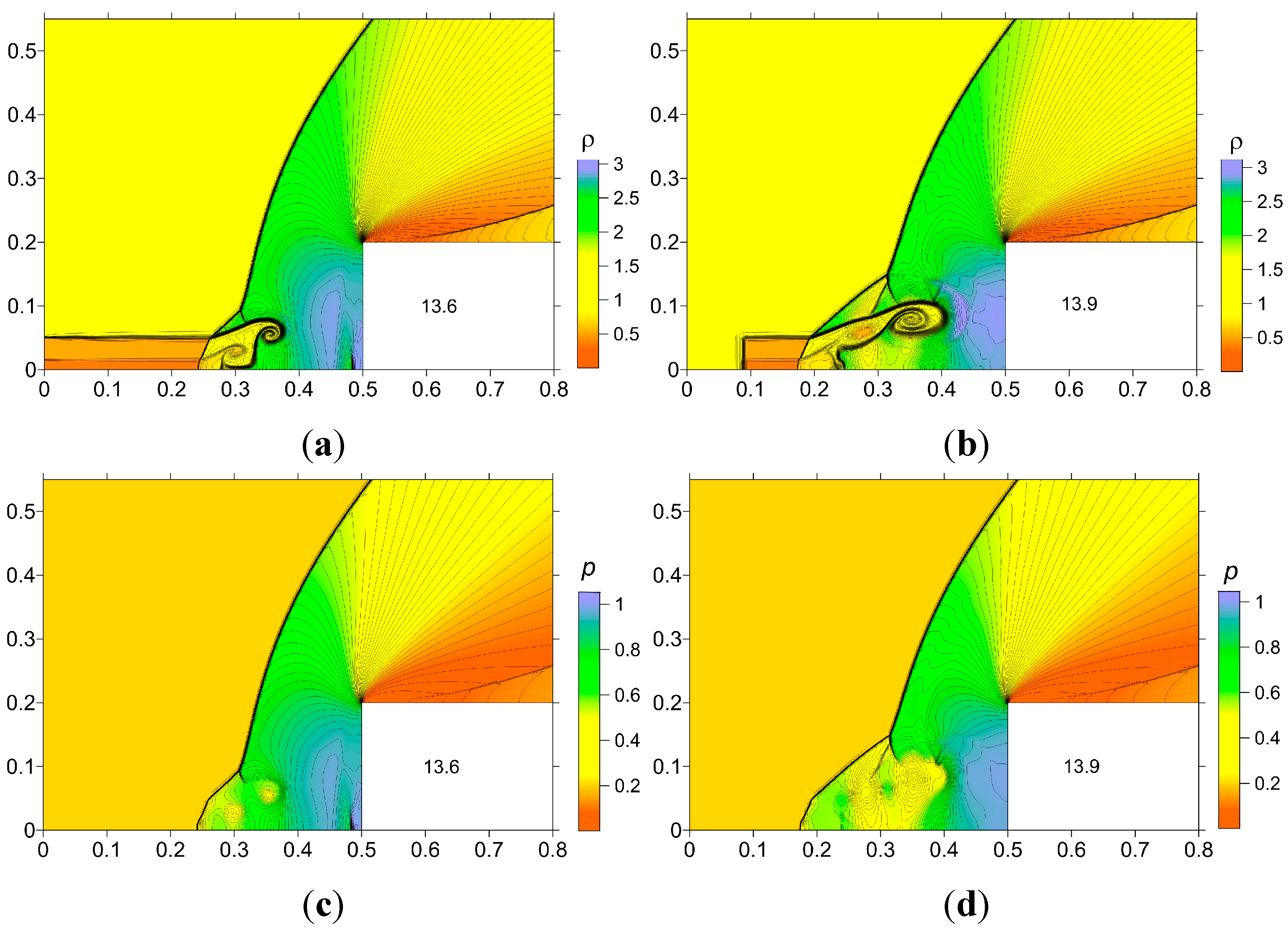
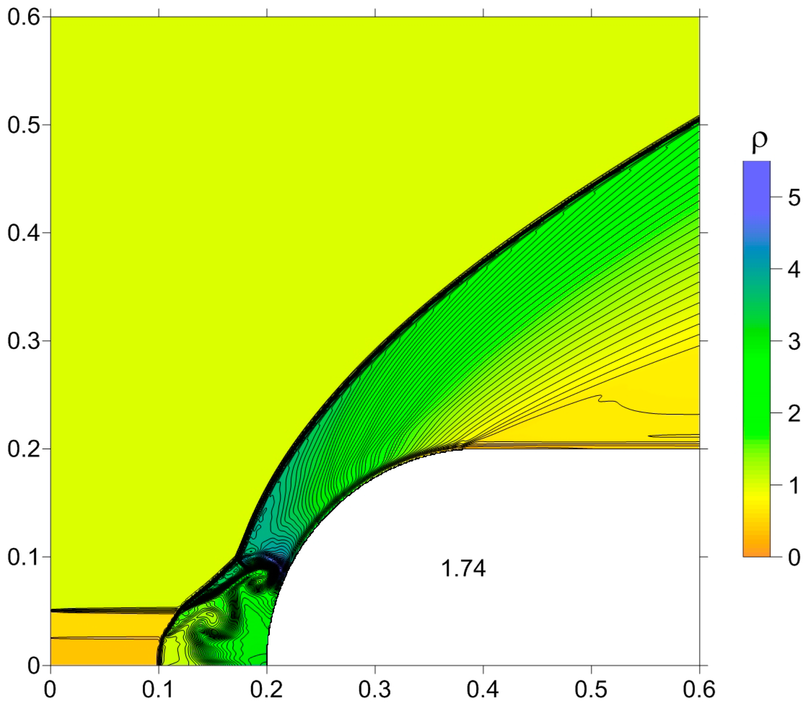
3.3. Interaction of the Combined Filament with the Supersonic Body “Hemisphere-Cylinder”
In this section the results of the interaction of different types of filaments with the supersonic body “hemisphere-cylinder” are presented (here
ti = 1.501). Superposition of two vortices’ effects on the half surface of the body (
Figure 8). The effect from the energy deposition is weaker for this shape of body but introducing the internal part strengthens it by 51.7% (
Figure 9a, see
Table 4). For the infinite filaments, a similar effect is obtained at the steady state (
Figure 9b).
Figure 8.
Beginning of the interaction, M = 3.45, αρ = 0.5, αρ1 = 0.35, t = 1.74.
Figure 8.
Beginning of the interaction, M = 3.45, αρ = 0.5, αρ1 = 0.35, t = 1.74.
Figure 9.
Dynamics of dimensionless frontal drag force, M = 3.45, αρ = 0.5, αρ1 = 0.35: (a) Bounded filaments; (b) Infinite filaments.
Figure 9.
Dynamics of dimensionless frontal drag force, M = 3.45, αρ = 0.5, αρ1 = 0.35: (a) Bounded filaments; (b) Infinite filaments.
Table 4.
Hemisphere-cylinder, M = 3.45.
Table 4.
Hemisphere-cylinder, M = 3.45.
| Type of Filament | (F0 − Fmin)/F0 (%) |
|---|
| Non-combined, d/D = 0.25, αρ = 0.5 | 23.6 |
| Combined, d/D = 0.25, d1/D = 0.125, αρ = 0.5, αρ1 = 0.35 | 35.8 |
3.4. Infinite Combined Filament/Supersonic Pointed Body Interaction
Consider the interaction of the infinite combined filament with the shock layer produced by the pointed body (with the half top angle equal to 45°) at M = 1.89 (ti = 4.01). Here the flow is planar and the calculation area includes two symmetrical parts. It is seen that the symmetrical vortex structure causing by the Richtmyer–Meshkov instabilities is generated. While the vortex structure is moving to the body, the pressure on the face of the body falls, causing the drag force reduction.
Figure 10.
Unsteady vortex structures in front of the body: density, αρ = 0.6: (a) Non-combined filament; (b) Combined filament, αρ1 = 0.4; (c) Combined filament, αρ1 = 0.8.
Figure 10.
Unsteady vortex structures in front of the body: density, αρ = 0.6: (a) Non-combined filament; (b) Combined filament, αρ1 = 0.4; (c) Combined filament, αρ1 = 0.8.
Comparison of the unsteady vortex structures in front of the body for non-combined and combined filaments is presented in
Figure 10. It is seen that for α
ρ1 > α
ρ the most complicated flow structure is obtained which is connected with the generation of the vortices rotating in opposite directions (
Figure 10c). The corresponding steady flow modes are presented in
Figure 11. One can conclude that these flow modes are quite different. The combined filament with α
ρ1 < α
ρ produces two constantly present vortices in front of the body (
Figure 11b). The combined filament with α
ρ1 > α
ρ produces two weaker vortices and the streams of more cold gas in the areas neighboring to the axis of symmetry close to the pointed part of the body (
Figure 11c).
Figure 11.
Steady fields of density, αρ = 0.6: (a) Non-combined filament; (b) Combined filament, αρ1 = 0.4; (c) Combined filament, αρ1 = 0.8.
Figure 11.
Steady fields of density, αρ = 0.6: (a) Non-combined filament; (b) Combined filament, αρ1 = 0.4; (c) Combined filament, αρ1 = 0.8.
The dimensionless dynamics of the front drag force
F are presented in
Figure 12. It is seen that the combined filament with α
ρ1 < α
ρ causes much greater frontal drag force reduction than another ones. In
Table 5 the face drag force values are presented during the first pulsation and for the steady flow mode (subscript “s”). It is seen that for α
ρ1 < α
ρ the effect of the combining energy sources achieves 60.8% (related to the non-combined one) for the first pulsation and 70.9% for the steady flow mode. The drag force reduction for α
ρ1 < α
ρ at the steady state is connected with two constantly effecting vortices in front of the body (
Figure 11b). It should be mentioned that the coarse grid is used in this part and small flow details in
Figure 12 are not resolved. However, in [
15] it is shown that on a coarse grid the applied difference schemes give the steady values close to their mean values on a fine grid.
Figure 12.
Dynamics of front drag force for different αρ1; αρ = 0.6.
Figure 12.
Dynamics of front drag force for different αρ1; αρ = 0.6.
Table 5.
Pointed body. M = 1.89.
Table 5.
Pointed body. M = 1.89.
| Type of Filament | (F0 − Fmin)/F0 (%) | (F0 − Fs)/F0 (%) |
|---|
| Non-combined, d/D = 0.25, αρ = 0.6 | 38.3 | 28.5 |
| Combined, d/D = 0.25, d1/D = 0.075, αρ = 0.6, αρ1 = 0.4 | 61.6 | 48.7 |
| Combined, d/D = 0.25, d1/D = 0.075, αρ = 0.6, αρ1 = 0.8 | 34.8 | 25.2 |
3.5. Examples of the Computational Convergence and Grid Independence
Consider the interaction of non-combined filament with supersonic shock layer over a blunt cylinder at
M = 1.89.
Figure 13 demonstrates the comparison of the results obtained with the use of three Cartesian difference grids with
hx =
hr (
Table 6).
Table 6.
Using difference grids.
Table 6.
Using difference grids.
| Characteristics | Coarse Grid | Fine Grid I | Fine Grid II |
|---|
| hx, hr | 0.001 | 0.0005 | 0.00012 |
It is seen that at the stage of the drag force reduction caused by the primary vortex action in the calculations with the use of the coarse grid (
Figure 13a) the main flow details are practically the same as in the case when the fine grid I is used (
Figure 13b). In the drag force dynamics the small scale details are less visualized than on the fine grid I (
Figure 13c). On the other hand, on the fine grid II the additional small scale details (secondary vortexes) are visualized and the base flow elements are retained (
Figure 14a,b). It can be concluded that computational convergence with decreasing space steps takes place in the applied difference schemes. Also, the results show that the chosen grids are sufficiently sensitive and the results are grid-independent in the sense of retaining the base flow elements.
Figure 13.
Density contours, t = 14.1: (a) Fine grid I; (b) Coarse grid (the body is moved on 0.05 to the right); (c) Front drag force dynamics: F1—fine grid I, F2—coarse grid; αρ = 0.5.
Figure 13.
Density contours, t = 14.1: (a) Fine grid I; (b) Coarse grid (the body is moved on 0.05 to the right); (c) Front drag force dynamics: F1—fine grid I, F2—coarse grid; αρ = 0.5.
Figure 14.
Density contours, αρ = 0.4: (a) Fine grid I; (b) Fine grid II.
Figure 14.
Density contours, αρ = 0.4: (a) Fine grid I; (b) Fine grid II.


