Investigation of a Morphing Wing Capable of Airfoil and Span Adjustment Using a Retractable Folding Mechanism

Abstract
:1. Introduction
1.1. Wingspan Morphing
- The aerodynamic area
- The wingspan
1.2. Camber Morphing
2. Materials and Methods
2.1. Endurance Improvement and Morphing Efficiency
2.1.1. Mission’s Scenario
2.1.2. Working Points and Morphing Efficiency
- Aspect ratio selection—The initial input parameter for the analysis was chosen to be the aspect ratio. However, it was possible to launch the analysis with any number of valid parameters: wing area, and wing loading to name a few.
- Drag assumptions—Skin friction coefficient and Oswald efficiency number were chosen from experience. Wetted area was also assumed to be a function of wing area and airfoil thickness so that ; this assumption serves to simplify the drag calculation.
- Drag calculation—A wing loading selection is made and using Equation (4) with the above input and assumptions yields drag data at specific wing loading and aspect ratio.
- Minimum power velocity calculation—The lift coefficient and drag force are estimated. The velocity at which the power requirement is minimal is calculated for the glider configuration and accordingly, the minimum power requirement velocity of the aerobatic configuration is also computed.
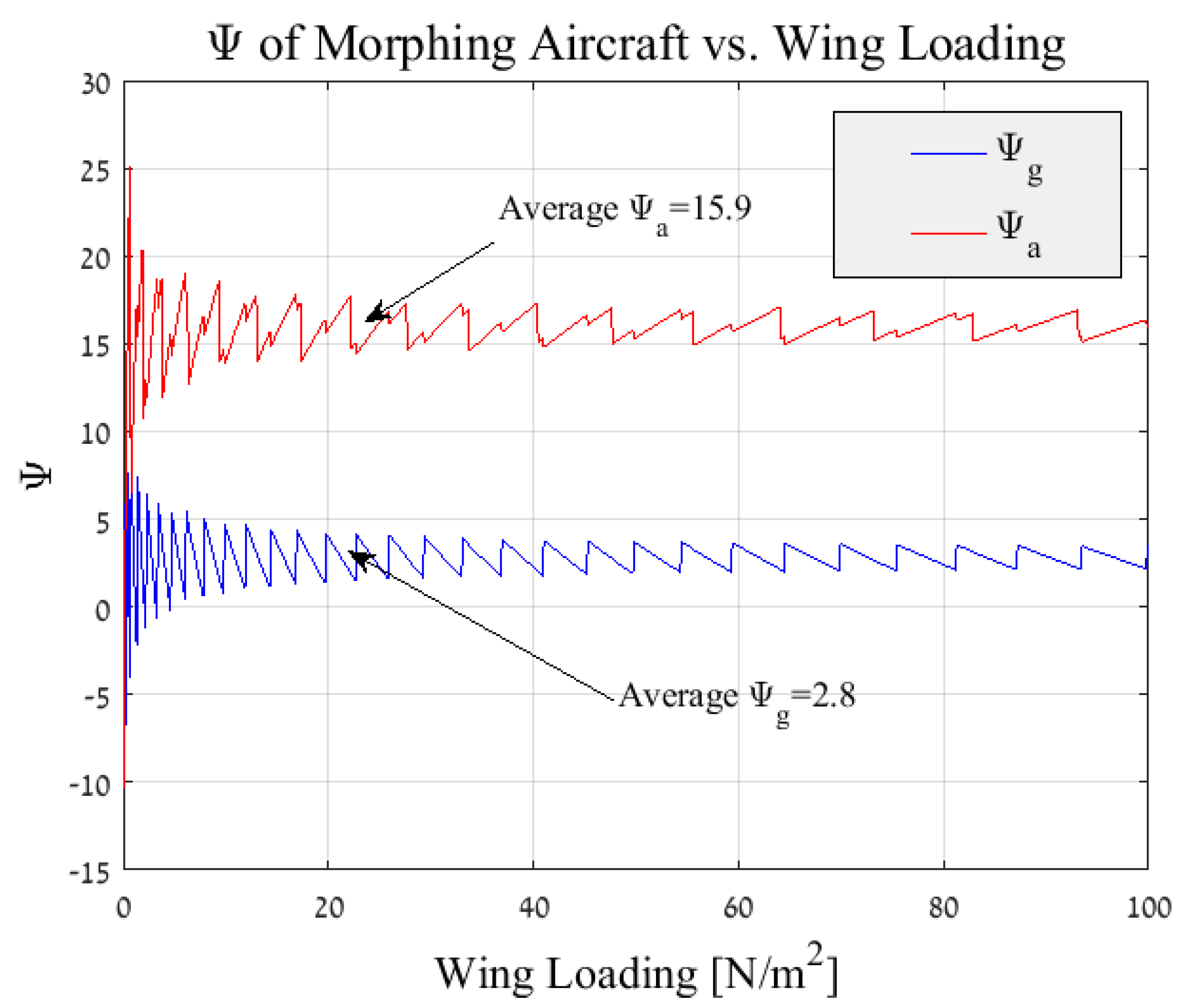
- Flight Scenario impact—A flight scenario is introduced into the analysis using and the morphing efficiency is calculated using Equations (7) and (8). In order to attain results at various wing loadings, an iteration loop is set from the drag calculation phase recalculating the efficiency at different wing loading values.Figure 7 depicts the morphing efficiency for a glider’s aspect ratio of and a flight scenario of . It can be seen that the morphing efficiency is quite constant above a minimal wing loading. Thus for most applications, an average can be made and a single value of efficiency per aspect ratio and flight scenario is attained. This stagnation in efficiency is due to the affect of the wing loading on the minimum power velocity which serve as a control loop that maintains a steady value throughout the examined wing loading spectrum.
- Final morphing efficiency calculation—Given a single value for the efficiency at every , an iteration loop is set from the aspect ratio selection (initial phase) and finally the calculating of the morphing efficiency at different flight scenario is obtained for a given spectrum of aspect ratios.Figure 8 and Figure 9 depict the results of the analysis for the morphing aircraft efficiency over the standard glider and aerobatic aircraft, respectively. Each line represents a specific and it is apparent that the flight scenario and aspect ratio are the main factors in determining the added value of the present morphing concept. As expected, for given flight scenarios that are defined with a larger value of (flight scenarios with increased phases of steady flight, such as loiter and others) the morphing efficiency or the “gain” from morphing over a standard glider is less prominent (see Figure 8). In a similar fashion, for flight scenarios that are defined with the same larger value of the morphing efficiency or the “gain” from morphing over aerobatic aircraft is increased (see Figure 9).Furthermore, it is visible that for this typical example the morphing efficiency is significantly higher than meaning that the power requirements are substantially lower for the morphing aircraft over its standard aerobatic counterpart. This is due to the behaviour of the power vs. velocity as is presented in Figure 5. During the flight phases where the standard aerobatic aircraft is required to maintain the glider’s velocity , the power is significantly increased, subsequently the overall efficiency is increased. However, during flight phases were the standard glider is required to maintain the aerobatic aircraft’s velocity , the power is indeed increased only not by the same magnitude leading to less “profit” for the morphing concept, yielding to a lower morphing efficiency.This is not a general conclusion and is bounded to the assumptions made during the analysis pertaining the drag and wetted surface functions.
2.1.3. Weight Consideration
2.2. Morphing Algorithm
Roll Stability during the Morphing Process
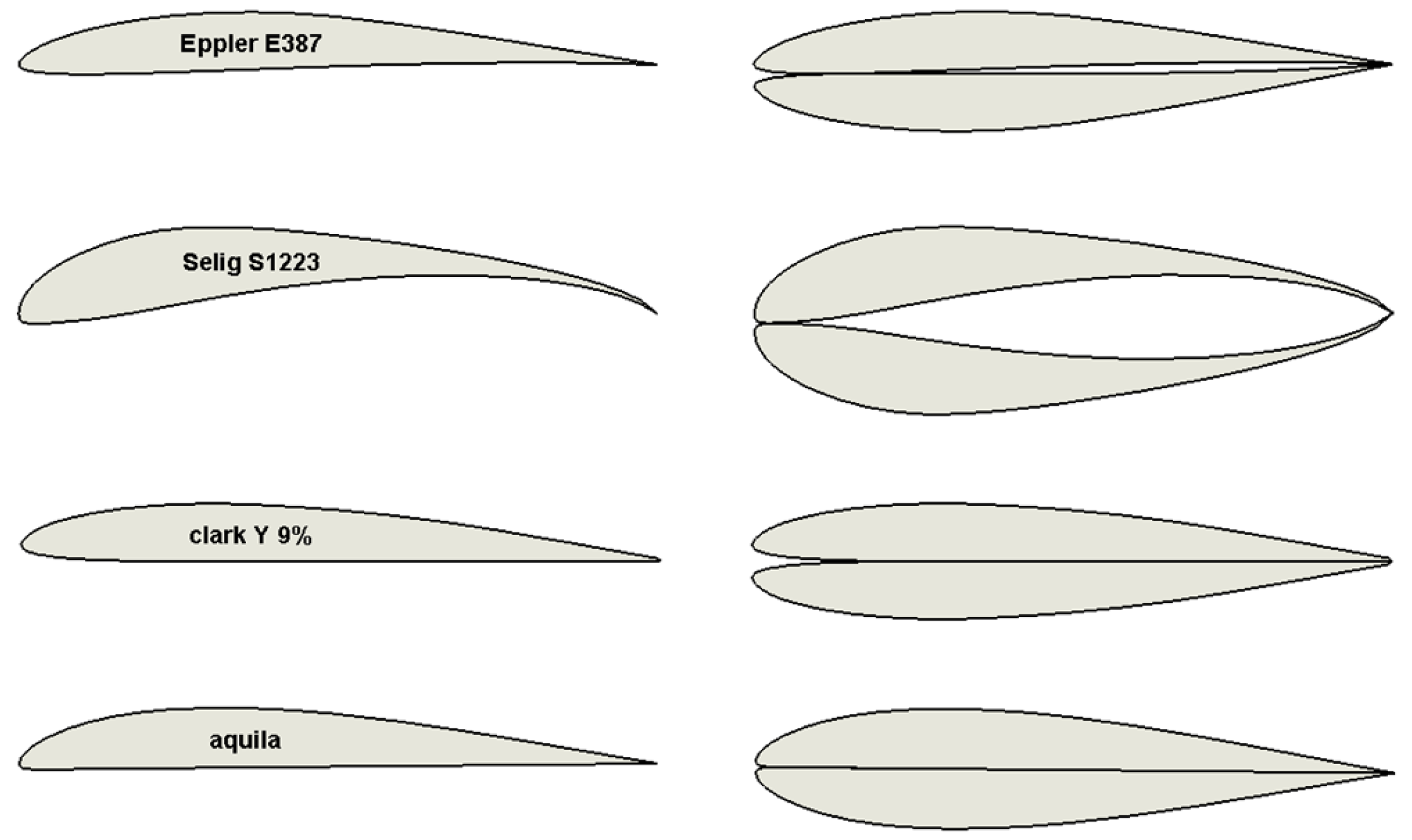
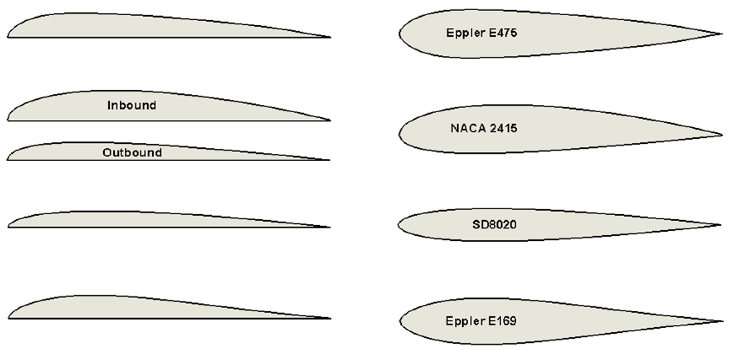
2.3. Airfoil Selection
2.3.1. Dominant Aerobatic Aircraft Working Point
2.3.2. Dominant Glider Working Point
- Surface panelIn this concept a single panel on the lower or upper surface of the wing would retract and pushed forward in a manner that would eliminate the gap. This concept can be realized by either two methods, either two panels from both the static and folding wings are used to close the gap, or a single panel originated from the static wing would solely perform the gap closing action. The latter method serves to reduce mechanism weight at the wing tips. The surface concept, if implemented, would result in a new airfoil, in which the leading edge gap is sealed from the airflow and can be visualized (in the most general way) as an airfoil with a single panel that connects the forward most points of the upper and lower surface (see Figure 17). Several airfoils were compared to an equivalent NACA 4 digit approximation airfoil. This was done in order to evaluate the adverse effect of the leading edge gap. This comparison might be considered fair, since the NACA 4 series airfoils represent improvements to the shape of the leading edge with minimal effect to the remainder of the chord-wise geometry of the airfoil and thus can alleviate some analysis complications for an early stage design.The closing of the leading edge via a NACA 4 digit approximation is valid for preliminary design and is likely to give good indication for either the mechanically closed gap as well as the original opened gap airfoil. As for the deeper gaped airfoils, the approximation is not as productive. It poorly predicts the mechanically closed gap and is further intuitive that these approximations will not correlate with the opened gap airfoil.
- Thickness reductionThickness reduction is an amending concept which eliminates the gap entirely by means of allowing the two wing sections to contract along their lower surface toward one another. This would be achieved by a flexible skin at the front lower surface which allows that two wing sections to merge into a more slick gap-less airfoil. The contracting form used for this procedure is based on two contact points between the two lower surfaces of the mirrored airfoil. An aft contact point at the trailing edge and a forward contact point at the origin of the gap (see Figure 18).Let us denote the angle of retraction as the angle between the chord line and the symmetry plane of the two airfoils with the symbol (see Figure 18), so that the angle between the two chord lines of the airfoils is .The gap can also be expressed as a function of the distance between the symmetry plane and the leading edge, noted . Reduction in diminishes the leading edge distance to the symmetry plane until , meaning that the gap is eliminated. The correlation between the two is presented in Equation (15).An investigation of the resulting parameters of thickness reduction method was performed; the airfoil used was an initially long-gaped airfoil, the outcome of a ClarkY 9% folding, possessing a 30.7%c gap prior to reduction. Figure 19 provides a visual representation of the assimilation of the two airfoils.At the gap is no more and the ’new’ airfoil can be assessed via conventional analysis tools which were unavailable up to this point.
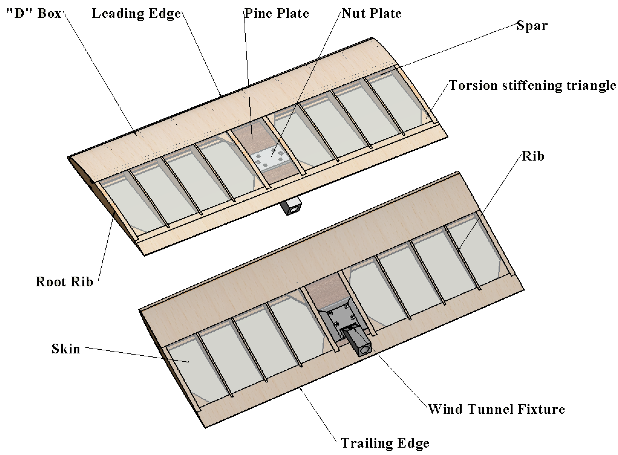
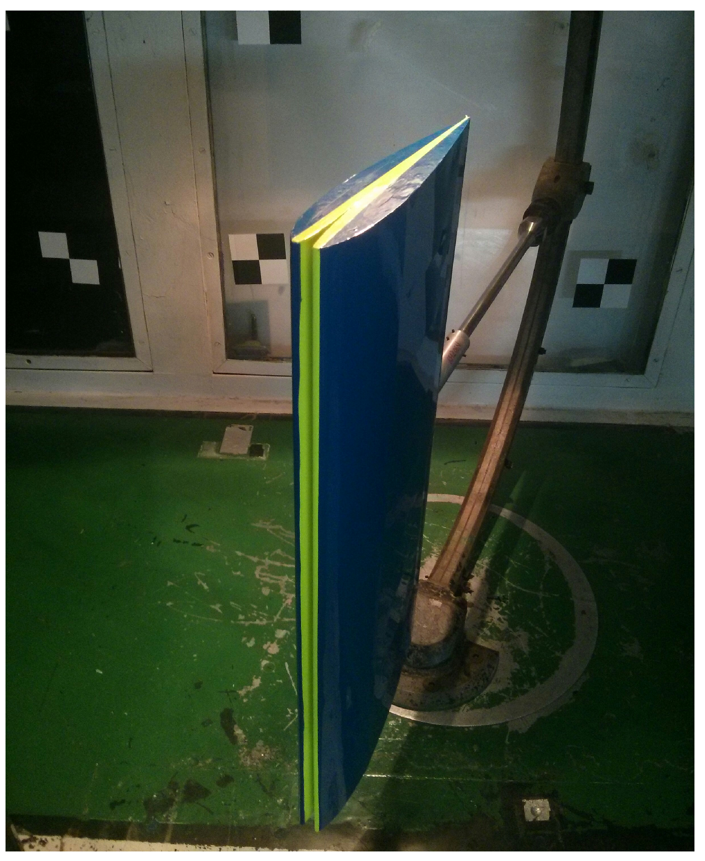
2.4. Wind Tunnel Models and Testing
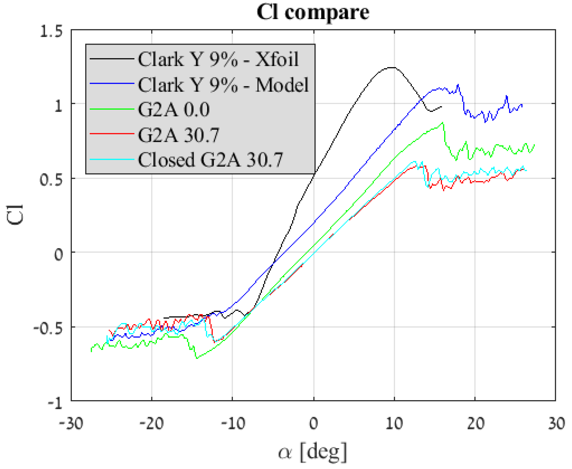
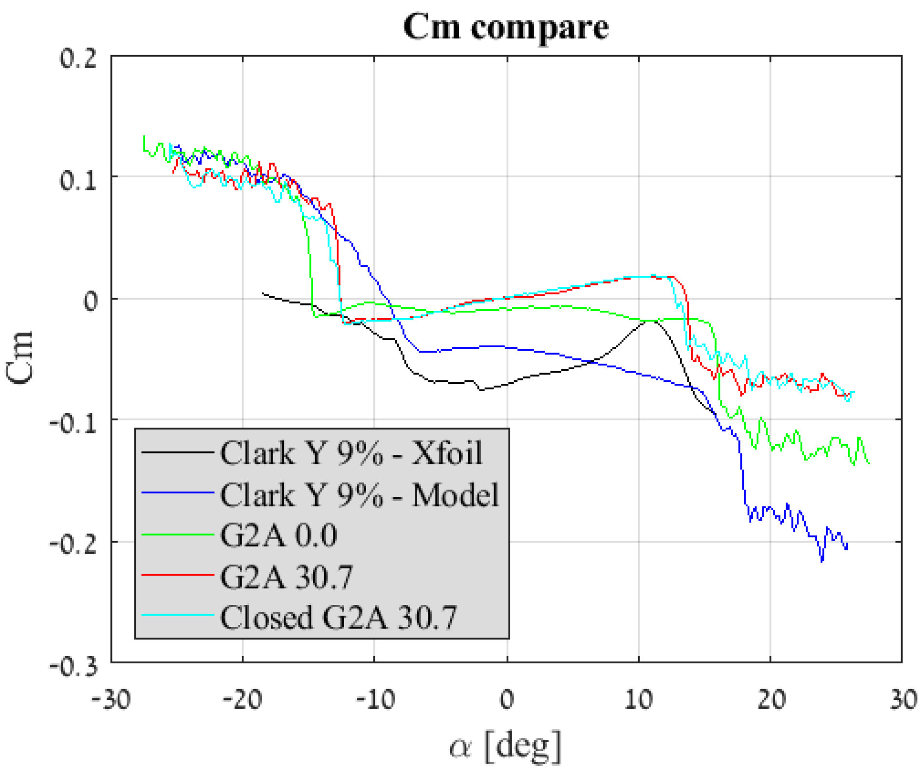
3. Results and Discussion
4. Conclusions
Author Contributions
Funding
Conflicts of Interest
Abbreviations
| Aspect ratio | |
| b | Wingspan |
| Horizontal stabilizer span | |
| Zero-lift drag coefficient | |
| Drag coefficient at maximum endurance condition | |
| Airfoil drag coefficient | |
| Skin friction drag | |
| Lift coefficient at maximum endurance condition | |
| Lift coefficient derivative of angle of attack | |
| Airfoil lift coefficient | |
| Pitch coefficient | |
| c | Chord |
| Added weight due to morphing mechanism | |
| Roll moment | |
| m | Mass |
| Total mission required power for an aerobatic aircraft | |
| Total mission required power for a glider | |
| Power required for levelled flight | |
| Power required for a manoeuvre or climb | |
| Total mission required power for a morphing aircraft | |
| Total mission required power | |
| S | Wing area |
| Horizontal stabilizer area | |
| Wetted area | |
| t | Thickness of airfoil |
| Velocity at maximum endurance condition | |
| Ideal aerobatic plane velocity for endurance | |
| Horizontal stabilizer volume | |
| Ideal glider velocity for endurance | |
| Stall Velocity | |
| W | Gross weight of the aircraft |
| Weight of morphing aircraft | |
| Wing loading of morphing aircraft | |
| Wing loading | |
| Leading edge distance normal to folded airfoils symmetry plane | |
| Anhedral angle | |
| Morphing added efficiency over aerobatic plane | |
| Morphing added efficiency over glider | |
| Angle of attack | |
| Angle of airfoil retraction | |
| Climbing angle | |
| Air density | |
| Portion of flight scenario governed by gliding conditions |
References
- Culick, F.E.C. The Wright Brothers: First Aeronautical Engineers and Test Pilots. AIAA J. 2003, 41, 985–1006. [Google Scholar] [CrossRef] [Green Version]
- Weisshaar, T. Morphing Aircraft Systems: Historical Perspectives and Future Challenges. J. Aircr. 2013, 50, 337–353. [Google Scholar] [CrossRef]
- Barbarino, S.; Bilgen, O.; Ajaj, R.M.; Friswell, M.I.; Inman, D.J. A Review of Morphing Aircraft. J. Intell. Mater. Syst. Struct. 2011, 22, 823–877. [Google Scholar] [CrossRef]
- Blondeau, J.; Richeson, J.; Pines, D.J. Design, development and testing of a morphing aspect ratio wing using an inflatable telescopic spar. In Proceedings of the 44th AIAA/ASME/ASCE/AHS Structures, Structural, Norfolk, VA, USA, 7–10 April 2003; Volume 1718, pp. 1–11. [Google Scholar]
- Samuel, J.B.; Pines, D.J. Design and Testing of a Pneumatic Telescopic Wing for Unmanned Aerial Vehicles. J. Aircr. 2007, 44, 1088–1099. [Google Scholar] [CrossRef]
- Polmar, N.; Genda, M. Aircraft Carriers. Volume 1, 1909–1945: A History of Carrier Aviation and Its Influence on World Even; Potomac Books: Washington, DC, USA, 2006; ISBN 9781574886658. [Google Scholar]
- Bourdin, P.; Gatto, A.; Friswell, M.I. Aircraft Control via Variable Cant-Angle Winglets. J. Aircraft 2008, 45, 414–423. [Google Scholar] [CrossRef]
- Abdulrahim, M. Morphing Flight Performance Characteristics of a Biologically-Inspired Morphing Aircraft. In Proceedings of the 43rd AIAA Aerospace Sciences Meeting and Exhibit, Reno, NV, USA, 10–13 January 2005; Volume 345, pp. 1–15. [Google Scholar]
- Manzo, J. Analysis and Design of a Hyper-Elliptical Camberd Span Morphing Wing. Master’s Thesis, Cornell University, Ithaca, NY, USA, 2006. [Google Scholar]
- Wiggins, L.D.; Stubbs, M.D.; Johnston, C.O.; Robertshaw, H.H.; Reinholtz, C.F.; Inman, D.J. A design and analysis of a morphing Hyper-Elliptic Cambered Span (HECS) wing. Collect. Tech. Pap. 2004, 5, 3979–3988. [Google Scholar]
- Davidson, J.; Chwalowski, P.; Lazos, B. Flight Dynamic Simulation Assessment of a Morphable Hyper-elliptic Cambered Span Winged Configuration. In AIAA Atmospheric Flight Mechanics Conference and Exhibit; American Institute of Aeronautics and Astronautics: Reston, VA, USA, 2003. [Google Scholar]
- Diaconu, C.G.; Weaver, P.M.; Mattioni, F. Concepts for morphing airfoil sections using bi-stable laminated composite structures Concepts for morphing airfoil sections using bi-stable laminated composite structures. Thin-Walled Struct. 2008, 46, 689–701. [Google Scholar] [CrossRef]
- Woods, B.K.S.; Bilgen, O.; Friswell, M.I. Wind tunnel testing of the fish bone active camber morphing concept. J. Intell. Mater. Syst. Struct. 2014, 25, 772–785. [Google Scholar] [CrossRef]
- Bettini, P.; Airoldi, A.; Sala, G.; Di Landro, L.; Ruzzene, M.; Spadoni, A. Composite chiral structures for morphing airfoils: Numerical analyses and development of a manufacturing process. Compos. Part B Eng. 2010, 41, 133–147. [Google Scholar] [CrossRef]
- Jenett, B.; Calisch, S.; Cellucci, D.; Cramer, N.; Gershenfeld, N.; Swei, S. Cheung, Kenneth C. Digital Morphing Wing: Active Wing Shaping Concept Using Composite Lattice-Based Cellular Structures. Soft Robot. 2017, 4, 33–48. [Google Scholar] [CrossRef] [PubMed]
- Shevell, R.S. Fundamentals of Flight; Prentice Hall: Englewood Cliffs, NJ, USA, 1989; Chapter 15. [Google Scholar]
- Drela, M. XFOIL: An analysis and design system for low Reynolds number airfoils. In Conference on Low Reynolds Number Airfoil Aerodynamics; Springer: Berlin/Heidelberg, Germany, 1989; pp. 1–12. [Google Scholar]


| Glider (g) | Aerobatic (a) | Value |
|---|---|---|
| b | Wingspan | |
| Aspect Ratio | ||
| S | Wing Area | |
| Wing Loading | ||
| t | Airfoil Thickness |
| Parameter | Clark Y 9% | G2A 0.0 | G2A 30.7 | Closed G2A 30.7 |
|---|---|---|---|---|
© 2019 by the authors. Licensee MDPI, Basel, Switzerland. This article is an open access article distributed under the terms and conditions of the Creative Commons Attribution (CC BY) license (http://creativecommons.org/licenses/by/4.0/).
Share and Cite
Geva, A.; Abramovich, H.; Arieli, R. Investigation of a Morphing Wing Capable of Airfoil and Span Adjustment Using a Retractable Folding Mechanism. Aerospace 2019, 6, 85. https://doi.org/10.3390/aerospace6080085
Geva A, Abramovich H, Arieli R. Investigation of a Morphing Wing Capable of Airfoil and Span Adjustment Using a Retractable Folding Mechanism. Aerospace. 2019; 6(8):85. https://doi.org/10.3390/aerospace6080085
Chicago/Turabian StyleGeva, Amit, Haim Abramovich, and Rimon Arieli. 2019. "Investigation of a Morphing Wing Capable of Airfoil and Span Adjustment Using a Retractable Folding Mechanism" Aerospace 6, no. 8: 85. https://doi.org/10.3390/aerospace6080085