Article

Reusable and Reliable Flight-Control Software for a Fail-Safe and Cost-Efficient Cubesat Mission: Design and Implementation

1
Faculty of Sciences Dhar El Mhraz, Université Sidi Mohammed Ben Abdellah of Fez, Fes 30050, Morocco
2
School of Science and Engineering, Al Akhawayn University in Ifrane (AUI), Ifrane 53000, Morocco
*
Author to whom correspondence should be addressed.
Aerospace 2020, 7(10), 146; https://doi.org/10.3390/aerospace7100146
Submission received: 12 August 2020 / Revised: 2 October 2020 / Accepted: 6 October 2020 / Published: 10 October 2020
(This article belongs to the Special Issue Verification Approaches for Nano- and Micro-Satellites II)

Abstract

:
While there is no rigorous framework to develop nanosatellites flight software, this manuscript aimed to explore and establish processes to design a reliable and reusable flight software architecture for cost-efficient student Cubesat missions such as Masat-1. Masat-1 is a 1Unit CubeSat, developed using a systems engineering approach, off-the-shelf components and open-source software tools. It was our aim to use it as a test-bed platform and as an initial reference for Cubesat flight software development in Morocco. The command and data handling system chosen for Masat-1 is a system-on-module-embedded computer running freeRTOS. A real-time operating system was used in order to simplify the real-time onboard management. To ensure software design reliability, modularity, reusability and extensibility, our solution follows a layered service oriented architectural pattern, and it is based on a finite state machine in the application layer to execute the mission functionalities in a deterministic manner. Moreover, a client-server model was elected to ensure the inter-process communication and resources access while using uniform APIs to enhance cross-platform data exchange. A hierarchical fault tolerance architecture was also implemented after a systematic assessment of the Masat-1 mission risks using reliability block diagrams (RBDs) and functional failure mode, effect and criticality analysis (FMECA).

1. Introduction

In order for a satellite to be operational, every system needs to operate correctly and in unison with the rest of the spacecraft main bus subsystems. It also needs to be robust enough to ensure continuous operation in spite of the outer space harsh environmental constraints. To satisfy all of these requirements, a flight-control software is implemented on the main on-board computer (OBC) of Masat-1 to manage and monitor the system and interface from the ground station. Masat-1 is a 1Unit nanosatellite with the dimensions of 10 × 10 × 10 cm and a maximum weight of 1.33 kg. It is a standardized format of nanosatellites known as Cubesats. This standard was established to expedite the aerospace mission design life cycle and decrease development costs while providing the same scientific capabilities as bigger aerospace programs. Since their creation in 1999, more than 400 nanosatellites have been launched by universities, industries and military. Indeed, as it is illustrated in Figure 1, the Cubesat market is growing. This is mainly because all these parties came to realize that a Cubesat is a cost-efficient ticket to space. Thereby, it is our intention to use the Masat-1 mission as an initiative to join the aerospace community [1,2]. The Masat-1 mission is led by three universities—the Univeristy Sidi Mohammed Ben Abdellah (USMBA), Al Akhawayn University in Ifrane (AUI), and the University Mohammed First of Oujda, and it is planned to be launched in late 2021 at a low Earth’s orbit. Masat-1 will also serve as an earning platform to enable capability building for developing a generic software architecture that is easy to modify and reuse, within minimal cost and time budgets for subsequent academic Cubesat missions. It is worth mentioning that since Masat-1 is our first space mission project, technical difficulties are prone to occur. Thus, Masat-1 development philosophy was to keep the design, implementation, and testing processes as simple as possible without compromising the main mission objectives. The main research problem could therefore be stated as follows: “What is the simplest, yet reliable and reusable design for the flight-control software to ensure Masat-1 mission success and reduce the inherent risks?”
With this aim in mind, further research questions were formulated:
  • What design and implementation approach shall we adopt given the Masat-1 mission objectives and design philosophy?
  • What concept of operations satisfies Masat-1 requirements; is it open or closed mode?
  • What standard risk assessment methods should we use to identify and prioritize the criticalities in the Masat-1 mission design, while considering the absence of accurate quantitative data in the early development phases of the mission?
  • Given the Masat-1 mission autonomy levels and the results of mission reliability and risk analysis, what fault tolerance strategies shall we employ to manage Masat-1 mission criticalities in a simple, efficient and low-cost manner?
  • Which architecture pattern shall we adopt to ensure the reliability and reusability of onboard flight software?
According to orbit analysis results [2], communication between Masat-1 and the ground segment is possible six times a day for an average 8.9 min during each pass. During the remaining time, it must survive on its own in the outer space harsh environment. Thus, Masat-1 is prone to anomalies/failures. Therefore, it should be able to handle those failures autonomously to ensure the mission safety till the next contact with the ground, especially when no hardware redundancy is supported. In this context, the flight software has to be as reliable as possible, while keeping its design simple and low-cost to reduce Masat-1 mission programmatic risks. In the literature, we surprisingly found little explicit formal works on satellites’ reliability and control software design within structured frameworks based on aerospace standards, such as the European Cooperation for Space Standardization (ECSS) system. Some graduate research dissertations were found. However, they usually report Cubesat mission development findings with specific technical information and little to no relevance to other missions [4,5,6]. In addition, no practical guidelines and workflows within standardized frameworks were described. Therefore, the rationale of this manuscript is to provide a practical and systematic approach to develop a reliable flight software for a low-cost Cubesat mission based on the application of fault detection, isolation and recovery (FDIR) concepts following the ECSS framework [7]. The standard approach for FDIR is to implement on-board procedures that executes a predefined set of actions to detect faults and manage failures [8]. Thus, a deep understanding and diagnosis of the failure scenarios is of paramount importance. Given the CubeSat mission peculiarities, formal reliability prediction and assessment methodologies are then necessary to prioritize satellite system criticalities. The findings of this analysis will justify the selection of the final design solution of the flight software in terms of writing or changing of the requirements, software patterns, and the definition of mitigation strategies. Thus, this work will also serve as a complement to the current literature on satellite reliability research through providing the relevant methodologies used, while considering some common constraints, such as a lack of the quantitative reliability data of components, “the absence of clear criteria for the specification of qualitative/quantitative requirements and lack of statistical confidence” [9].
To address the previous research questions, this manuscript has been organized in the following way: Section 2 introduces the reader to the design and development approach of Masat-1 throughout its life cycle. Section 3 provides an overview of Masat-1 autonomy levels and main bus architecture with a focus on the hardware architecture of the onboard computer. To increase Masat-1 mission reliability, Section 4 describes the FDIR strategies and concepts applied during the design phase with a focus on functional FMECA—failure mode, effects, and criticality analysis—for a systematic identification of the possible failure scenarios. Section 5 analyzes the Masat-1 flight software-derived requirements. Then, Section 6 outlines the Masat-1 concept of operations—CONOPS. Finally, the software architectural design was explored, and the main features of the detailed design and implementation are presented in Section 7. Additionally, this section describes how the Masat-1 flight software functional requirements and quality attributes were implemented.

2. Masat-1 Mission Design Approach

In addition to Masat-1 educational purpose, the primary goals of Masat-1 mission are the following:
  • Develop a reliable bus architecture to withstand outer space harsh environmental conditions that is reusable for subsequent student Cubesat missions;
  • Establish a reliable communication link with the control ground station;
  • Capture the images of target earth locations using an off-the-shelf high-resolution camera.
Within these objectives, we established in a previous work [1] a generic framework by tailoring the ECSS system to define a feasible and reliable architecture for the Masat-1 mission, while addressing the peculiarities and inherent risks in the operational context of aerospace projects. The full ECSS standard was beyond the scope of low-cost Cubesat missions such as Masat-1. Therefore, ECSS standard tailoring ensures the efficient development and testing of Masat-1 proto-flight within the scope of the project budgets and boundaries. ECSS standards were chosen over SMAD—space mission analysis and design standard system, that was proposed by the National Aeronautics and Space Administration (NASA), because they offer comprehensive and user-friendly guides to the management and development processes throughout the mission life cycle. Within this framework, we adopted an iterative and recursive systems engineering approach, to cope with the eventual changes and updates during the design and development process (Figure 2). This approach shall also facilitate the functional breakdown of Masat-1 systems to a level of detail, concrete enough to easily elicit high-level and derived requirements, to identify, prioritize and manage Masat-1 mission criticalities, to implement the smallest component and identify interfaces and task flows, and then to integrate it into larger subsystems until the proto-flight has been assembled, tested and validated.
In order to come up with a reliable and reusable software architecture for Masat-1, the project’s context needs to be clear. Therefore, mission objectives, autonomy levels, and available resources were defined. Then, mission budgets analysis—orbit analysis, power budget and communication budget analysis—was conducted. With the orbit known and budgets established, the Masat-1 functional breakdown tree was generated, and the system requirements were elicited and refined. Thereafter, we established Masat-1 mission CONOPS to define in detail what the system is supposed to do during each phase of the mission. Finally, the preliminary software architecture was defined, and detailed design requirements can be reached.
Throughout Masat-1 design and the development of a life cycle, we intended to follow the KISS (keep it simple stupid) principle and off-the-shelf technology was leveraged [1,2]. Indeed, using qualified commercially-off-the-shelf (COTS) system-on-module products with proven flight heritage seemed more viable, reliable and low-cost than in-house custom-made components.

3. Masat-1 Mission Overview

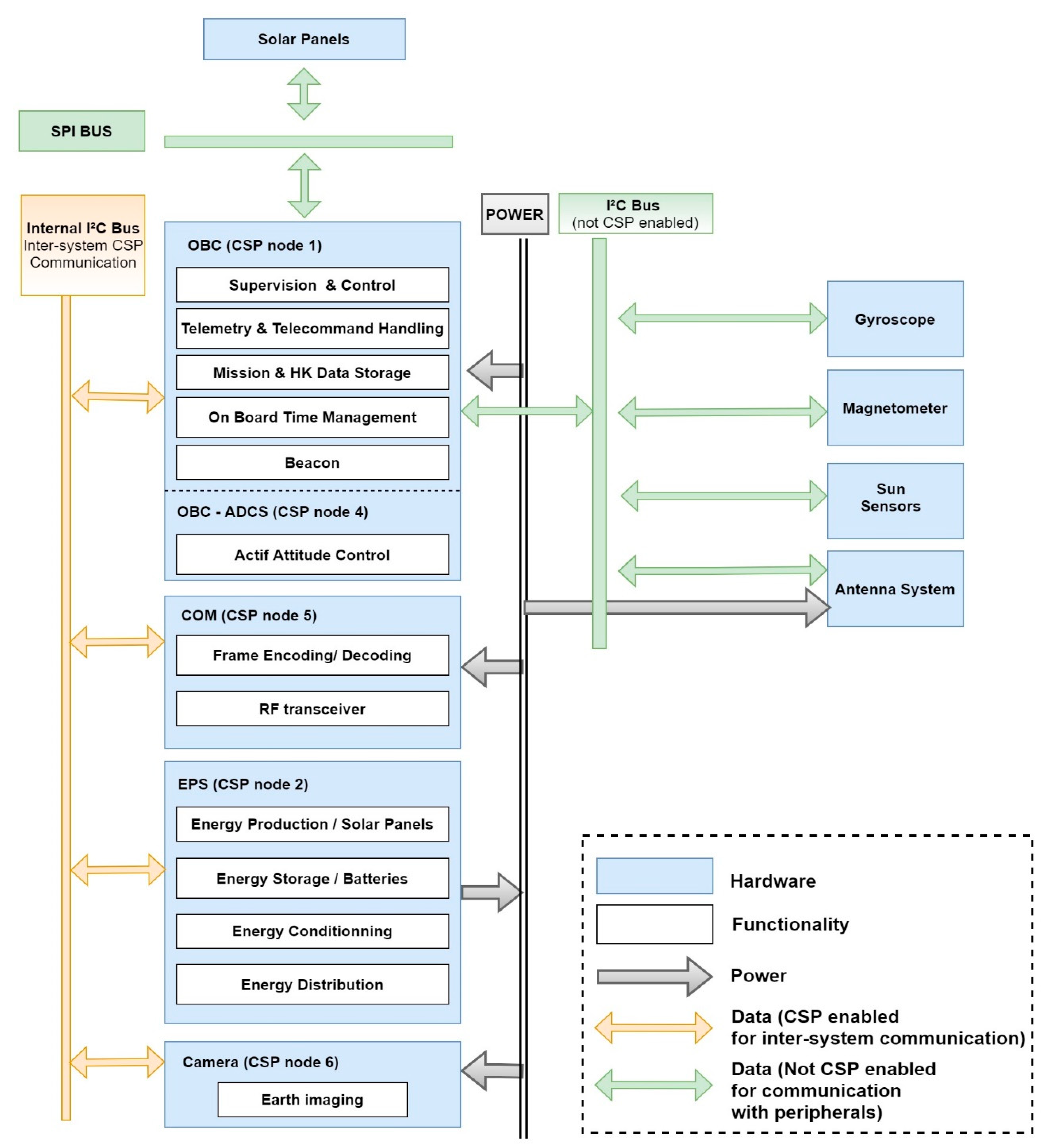
3.1. Masat-1 Mission General Architecture

Masat-1 uses a 1Unit Cubesat form factor, and it is implemented using COTS modules with extensive flight heritage. To simplify the mechanical and electrical interfaces of the satellite, these modules are designed to the PC/104 standard [10]. The main subsystems implemented onboard Masat-1 include: structure, onboard computer (OBC), active attitude determination and control system (ADCS), electrical power system (EPS), communication system (COM), and a camera as mission payload. The EPS system consists of the power management and distribution unit, batteries and solar panels. The COM system includes a UHF half-duplex transceiver and an omnidirectional dipole antenna. Figure 3. illustrates the Masat-1 main bus architecture. We will not elaborate on each of these subsystems, instead we will focus on the OBC system.
The Masat-1 command and data handling system design revolve around one single board computer. Using this centralized architecture allows the satellite to rapidly respond to commands and efficiently manage the unexpected issues. Masat-1 OBC main responsibilities are time synchronization, housekeeping data collection and storage, spacecraft health monitoring and anomalies’ handling, power consumption monitoring, event reporting and memory management. It is also responsible for the satellite functions/mode activation/deactivation to set the satellite state appropriately. Moreover, the OBC acts as a gateway between the satellite main bus subsystems and the ground station; all commands received from the ground are executed only after verification, and telemetry—payload and housekeeping data—are downlinked to ground upon the operator request. That is to say, the OBC system is a vital component and Masat-1 mission success strongly relies on its efficiency and reliability, especially when no full redundancies were supported onboard. Therefore, resiliency against the harsh environmental constraints of outer space is a crucial requirement for Masat-1 OBC. For this mean, we chose to exploit qualified off-the-shelf products with extensive flight heritage. To ensure the proper selection of a qualified COTS System-on-Module OBC for Masat-1 while considering the previous requirements, the following choice criteria were identified: energy consumption, calculation power, temporal reference generation, and memory storage. Then, a comprehensive statistical study was carried out to investigate different OBC hardware architectures used in 39 Cubesat missions launched since 2003 [2]. Based on the experience of these missions and Masat-1 OBC requirements, we selected a COTS module that is based on a new AVR32 RISC architecture with advanced power-saving features designed for on-board applications with limited resources. The Masat-1 OBC module is empowered by the Atmel AT32UC3C0512C microcontroller. In addition to its high calculation power and low mass, the selected module also features various memories and communication interfaces. The board supports a 128 MB NOR serial flash for storage. ROM/Flash memory shall be used as a mass memory for operating system storage and custom flight-control software since it is radiation resistant. It will also contain the bootloader and shall serve as a safe backup of permanent application data and spacecraft housekeeping data log. For applications which require more ram than what is supported in the MCU, the board also has 32 MB SDRAM connected to the microcontroller. Masat-1 OBC board main interfaces to other subsystems are CAN and I2C.
To be able to communicate both with the ground station and the rest of the satellite, the OBC is connected to the onboard transceiver via I2C main bus. Two I2C controllers are supported onboard; one for the main bus and the other can be used as the interface to external I2C components such as the antenna system or additional payloads. For interfacing with SPI devices, the board has one external connection with three chip selects. Furthermore, the RTC chip on the board also functions as a processor companion while 32 kB of FRAM provides nonvolatile storage.

3.2. Masat-1 Mission Execution Autonomy Levels

As illustrated in Table 1a,b, a spacecraft autonomy level is defined by its level of independence from ground support when achieving mission objectives. According to ECSS standards [4], spacecraft autonomy is the lowest when onboard operations rely mainly on ground control, and only limited on-board capabilities are implemented to deal with anomalies when the satellite is out of contact with the ground. On the other hand, the autonomy level of a spacecraft is the highest when goal-oriented mission operations are automatically executed on-board without any intervention from the ground.
To address the research questions stated in the introduction while ensuring software design simplicity, Masat-1 mission execution shall be mainly under ground control during contact windows and only limited on-board intelligence will be implemented. Therefore, the autonomy level E2 has been chosen for Masat-1 mission. Besides, Masat-1 is an Earth-observation mission. Thus, during failure scenarios, mission availability is not our foremost priority; short mission interruptions are allowed and have no consequences. In our case, ensuring spacecraft recovery is of more paramount importance than mission follow on. Hence, fault isolation and management autonomy level F1 were chosen; a simple FDIR strategy was used to lead the spacecraft to its safe mode during major on-board errors/failure cases, waiting for ground intervention.

4. Masat-1 Mission Fault-Tolerance Management: Concepts and Analysis

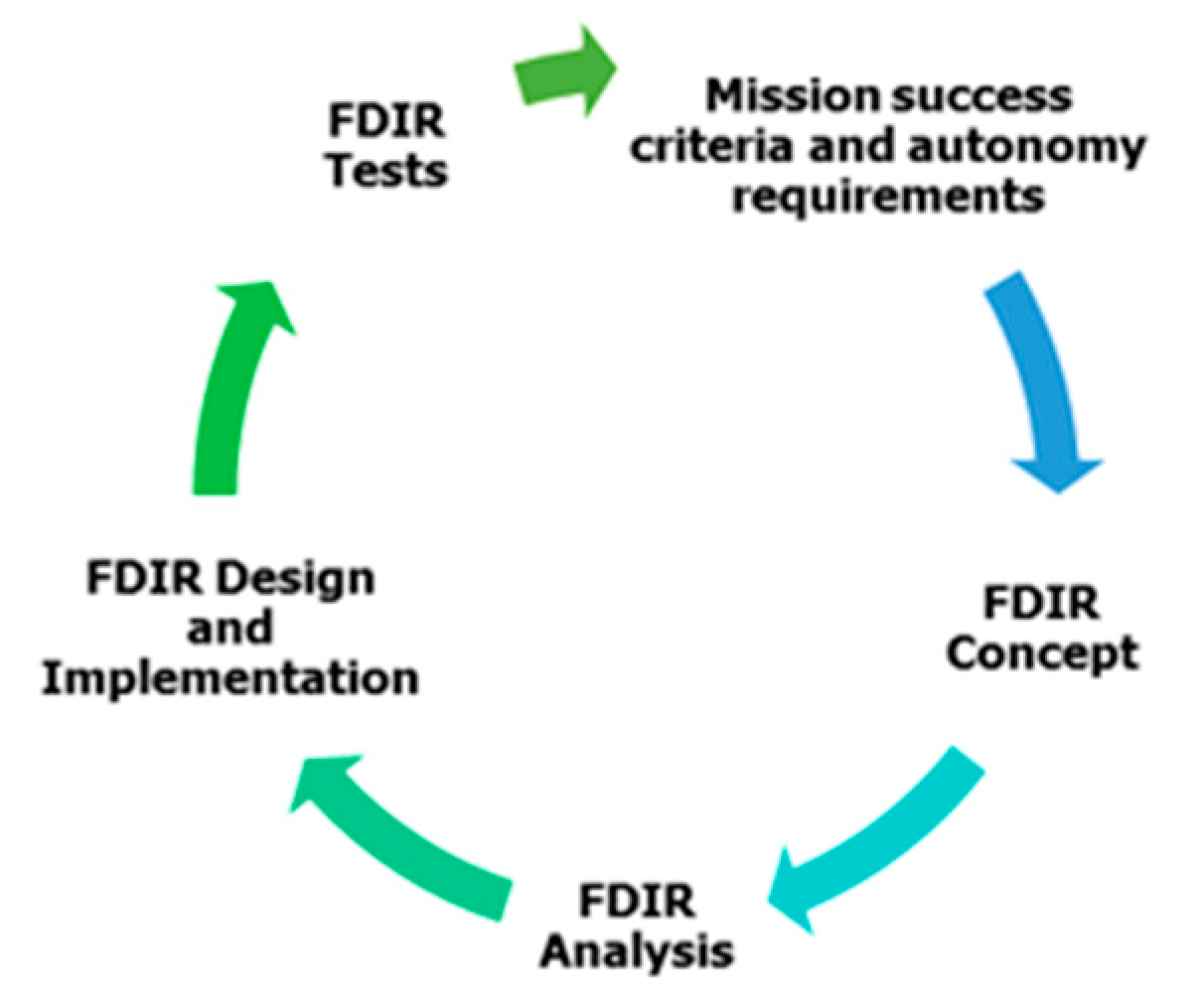
4.1. FDIR Concepts and Strategies

Fault detection, isolation and recovery (FDIR) analysis main goals are to detect anomalies, isolate the problem, and recover spacecraft systems and capabilities. FDIR analysis is a highly iterative process (Figure 4). First, the mission success criteria, autonomy levels and constraints are defined. Then, the system functional indentures are identified, and FDIR boundaries are defined in respect of the project; this is to prevent unnecessary analysis expansion and a waste of effort and time. Subsequently, the FDIR concepts and strategy are described. After that, a list of system and subsystem failure modes is developed using systematic reliability analysis tools [5]. Finally, the mission FDIR procedures are defined, and candidate contingency scenarios are proposed to perform verification and validation tests. The latter falls outside the scope of this paper, and it shall be the subject of further works.
In the literature [12,13,14], we identified two FDIR strategies: half-satellite’s and hierarchical FDIR strategies. In the half-satellite’s FDIR strategy, no isolation is performed when an anomaly is detected, instead the spacecraft is fully configured to switch to redundant units. Then, the failed components are recovered during the next contact with the ground. This strategy is quite simple as it requires basic validation mechanisms. On the other hand, the hierarchical FDIR is based on hierarchical levels, thus providing a graduated reaction depending on the fault/failure criticality. Therefore, it enables failure recovery at the lowest levels, isolation is guaranteed, and the effects perimeter is minimized. Besides, the hierarchical FDIR can be defined to match the project breakdown for organizational needs.
Given the Masat-1 financial budget, the hardware redundancy of the main bus subsystems was not an option. Moreover, it was decided to keep Masat-1 mission execution autonomy as low and simple as possible. Thus, the hierarchical FDIR strategy is a better fit for the mission objectives and needs. Since the Masat-1 platform was developed using off-the-shelf modules, hardware redesign or implementation changes are definitely not an option. Therefore, the FDIR analysis have been performed early enough to influence only Masat-1 software design given the hardware architecture previously defined. That is to say, we focused mainly on failure modes that can be detected and corrected through ground command and onboard software procedures. All other hardware failures are considered as catastrophic. FDIR implementation at the unit level falls outside the scope of this work, and FDIR functions are implemented only in the subsystem and mission levels.

4.2. Failure Mode, Effect and Criticality Analysis (FMECA)

In the literature, there are two approaches used in risk assessment and management: (i) a purely statistical approach and (ii) an analytical approach. Purely statistical methods rely on testing a sample of a population either for a pre-defined duration or until the wear-out of every unit of the sample [15]. Thereby, the mean time to failure (MTTF) is recorded, and the units’ reliability can be calculated. On the other hand, analytical methods can be used in either a quantitative or a qualitative manner. Qualitative risk assessment focuses on tracing the causes and effects of failure events. This can be executed using inductive (bottom-up) or deductive (top-down) analytical approaches. As for quantitative methods, they provide estimations about failure severity and their probability of occurrence. During the analysis phase of the FDIR process for Masat-1 (Figure 4), several analytical tools can be used such as FMEA—failure mode and effect analysis and its variant FMECA, FTA—fault tree analysis, ETA—event tree analysis, and RBD—reliability block diagram [5] to optimize the process of reliability analysis. In the remaining part of this section, we highlight the strengths and drawbacks of two popular tools in civil aerospace, FTA and FMEA/ FMECA.
FTA is a deductive top-down method based on the principle of multi-causality [7,16,17]. It is used to trace backward the potential causes of every failure event of a system. This contrasts with the FMEA analysis. The latter is a systematic, inductive and usually bottom-up analysis tool. It focuses on tracing forward the effects of a single component/function failure on the performance of different system levels. This analysis is systematically carried out for all the components in a system. Therefore, whilst the FTA focuses on identifying the interrelationship between the events inducing a top-level adverse effect [18], FMEA highlights all adverse effects caused by a single component failure. Consequently, unlike bottom-up FMEA, FTA is uncapable of exhaustively defining all initiating events of all potential failure scenarios.
In the literature [16,19], there are different types of FMEA analyses, namely functional (top-down), piece-part (bottom-up) and process. The piece-part approach (bottom-up) approach is hardware oriented. It is used when a system concept has been decided, and hardware items can be uniquely identified from the schematics and design data. This approach yields comprehensive results because all components at the lowest level of the system are considered, thus all potential failures are identified. Although it is time-consuming, the piece-part approach is a better fit when every component of a system must be reviewed. However, it will become inefficient when analyzing complex systems requiring progressive analysis or when analyzing incomplete systems during early design phases. It is also inadequate to provide risk-related information for a focused problem within the predefined boundaries of an existing system. Unlike the piece-part approach, the functional FMEA approach is function oriented. Thus, it lends itself extremely well to this type of problem. Functional FMEA is also a better fit to directly address only the most important contributors to major potential problems with significant effects on the system rather than every failure of each component. Intrinsically, functional FMEA results may not be comprehensive; not all failure events in a system may be covered, only major ones. It is also unable to identify the complex failure scenarios involving a combination of multiple failure modes within a subsystem. This is the reason why in practice functional FMEA is commonly used along with FTA or RBDs. A brief description of RBD analysis is provided in the next section.
By adding a criticality analysis, the purely qualitative FMEA can be made quantitative. According to MIL-STD-1629A and ECSS-Q-ST-30-02-C standards [7,20], FMECA analysis can be used following either a qualitative or a quantitative approach. The ECSS-Q-ST-30-02-C standard clearly suggests that: “The qualitative approach based on engineering judgment shall be used if specific failure rate data are not available” [7]. Following the qualitative method, the severity levels and likelihood of occurrence are assigned to each potential failure effect, and the criticality number is calculated. Then, a criticality matrix of severity versus occurrence is used to prioritize failures according to risk levels [7].
In summary, we selected functional FMECA in conjunction with RBD analysis for Masat-1 mission risk assessment and management mainly because the scope of our study is limited to the subsystem level, given the aforementioned design constraints in Section 4.1. We aim to use functional FMECA in an iterative and timely manner to increase its effectiveness. A quantitative analysis was not possible because of the absence of quantitative data about specific failure rates and the probability of occurrence for COTS. As Stesina et al. reported in [21], “anomaly analysis is complicated by the absence of a statistic database for Commercial Off-the-Shelf (COTS) items limiting the reliability analysis to a qualitative exercise without effective quantitative estimations”. Instead, a qualitative approach of functional FMECA was used as per ECSS-Q-ST-30-02-C standard suggestion. Therefore, the scores of each failure mode were assigned based on the statistical studies and results of similar FMECA studies reported in previous Cubesat missions, such as Lumio [8], Swampsat [22] and e-st@r missions. Using functional FMECA, we could identify all major failure modes of each subsystem in Masat-1 and assess the resulting consequences. As a result, adequate FDIR design provisions and testing plans were defined. In our case, this step was essential to devise a reliable solution for Masat-1 flight-control software, and hence assure the Masat-1 mission reliability. According to the ECSS-Q-ST-30-02-C standard, the sequence of functional FMECA activities is summarized as follows [7,23]:
Step 1 
Provide system schematic diagrams such as reliability block diagrams (RBDs) or system functional diagrams for a system description that is detailed enough to match both the targeted depth of the analysis and the current design maturity;
Step 2 
Fill out the FMECA worksheet which contains the following elements: all potential failure modes for each functional block of the system, all potential causes of the failure mode (optional), the worst potential consequences locally and on other subsystems, failure detection methods (optional), and methods to prevent or recover from each failure mode. It also assesses the failure criticality number (CN) given the worst potential severity level of the failure (SN) and its probability of occurrence (PN). The severity and probability categories were customized according to Masat-1 requirements and constraints. They are listed in Table 2a,b, respectively. The CN is calculated as the product of the ranking assigned to each factor: CN = SN × PN. It is worth mentioning that combinations of failures are not considered, and each single item failure is assumed to be the only failure in the system [5];
Step 3 
Define the overall mission critical items list (CIL): an item is critical if its failure mode severity is classified as catastrophic, or if a failure mode CN is greater or equal to 6 in conformance with the criticality matrix (Table 3);
Step 4 
Define corrective/preventive solutions (such as design provisions or operator actions) necessary to eliminate the failure or to mitigate/control the risk.

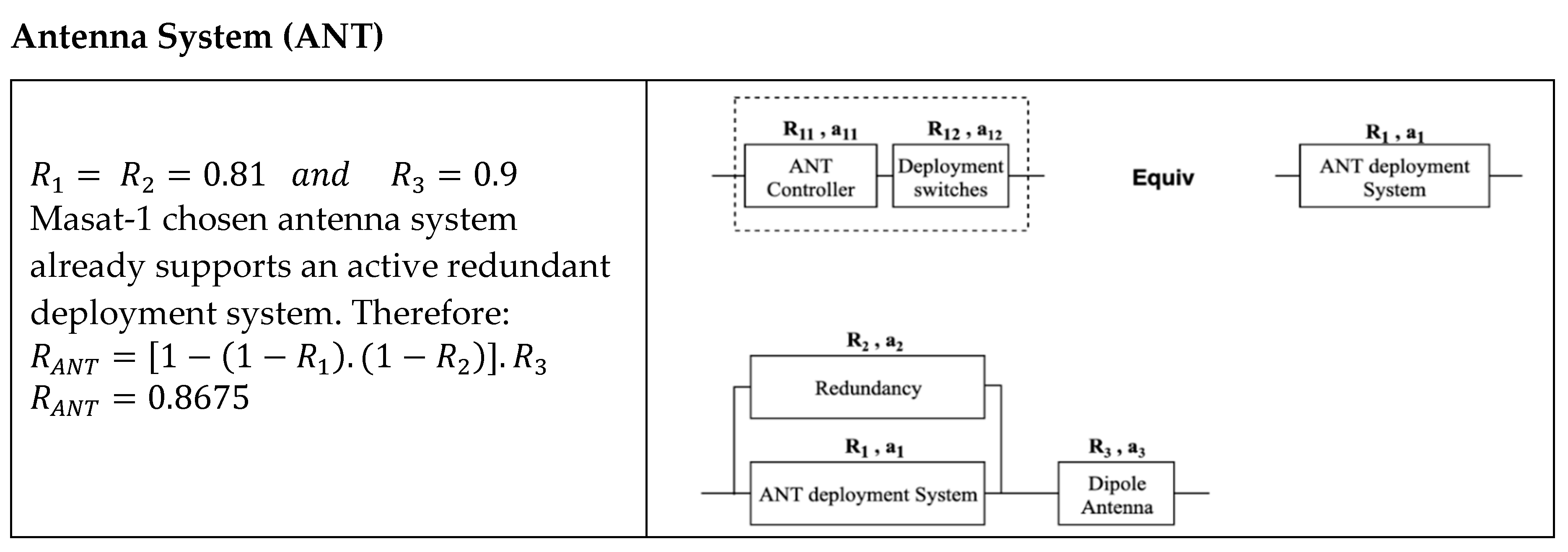
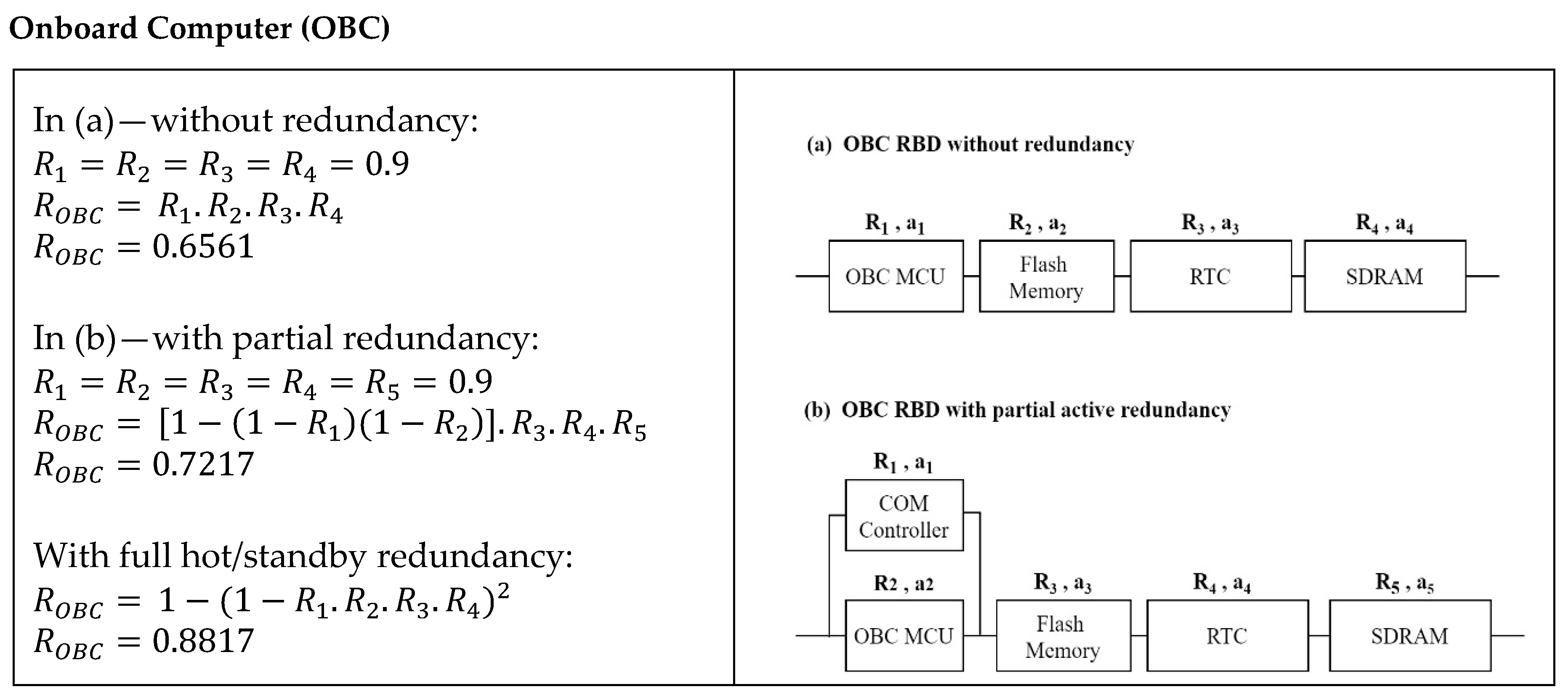
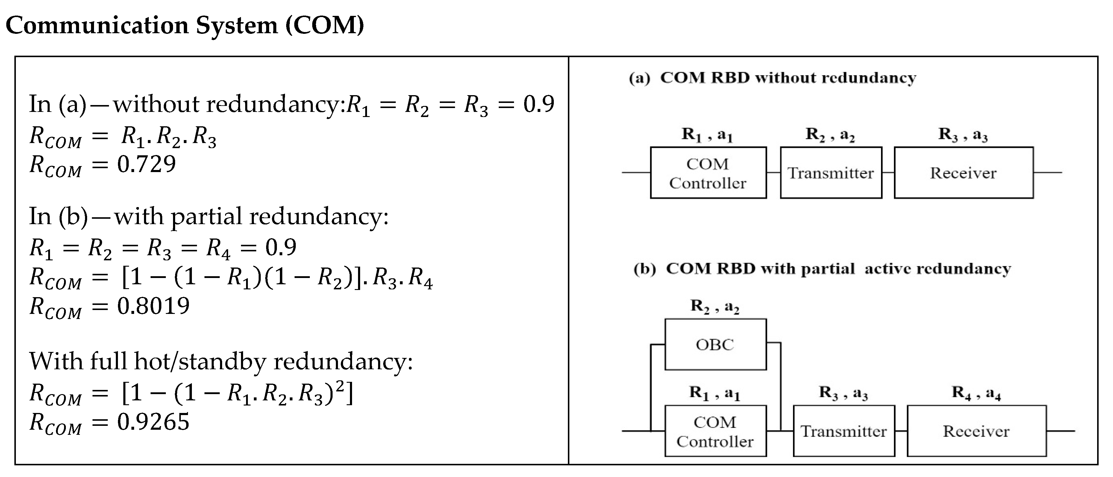
4.3. Masat-1 Reliability Block Diagram Analysis

Defining a functional RBD requires system functional partitioning into blocks with clearly defined tasks. The blocks are then linked depending on their effects on the system; for each required function, necessary blocks are connected in series, while blocks ensuring redundancy are connected in parallel. Obviously, the ordering of the blocks in series is arbitrary [16].
The system reliability Rs of N serial blocks and N parallel blocks are computed using Equations (1) and (2), respectively:
R s = Π i = 1 N R i
R s = 1     Π i = 1 N ( 1 R i )
It is worth mentioning that connectors and EEE parts failures are mainly due to vibrations, mechanical loads, short-circuits, extreme thermal conditions, etc. Such events might jeopardize the whole mission. Unfortunately, they cannot be prevented/corrected by Masat-1 flight-control procedures only. In addition, hardware design enhancement is beyond the scope of the Masat-1 mission. Therefore, selecting COTS modules with extensive flight heritage, previously used in successful missions, seemed to be the right decision to improve Masat-1 reliability. Indeed, to ensure COTS products robustness, manufacturers usually account for the effect of these events early on during the development phase, and they undertake extensive functional and environmental testing on design/qualification models under nominal and sub-optimal circumstances. Besides, at the time of the writing of this paper, no quantitative data about the failure rate of each COTS item were available or found in the literature [21]. Thus, we limited RBD analysis to the subsystem level, and the following assumptions were made to simplify the calculations for the Masat-1 RBD analysis:
  • All parts have a constant failure rate (a(t) = t);
  • As we previously mentioned, all parts used in Masat-1 are qualified COTS, from the same manufacturer, with extensive flight heritage in successful missions. Thus, we assumed that they have the same reliability, R = 0.9;
  • Thermal and environmental characteristics are not considered; only system architecture is considered for the reliability calculation;
  • Major parts such as the controller and the memory are considered to calculate reliability. Connectors and EEE parts such as resistors and diodes are neglected;
  • Redundancy switching mechanisms are considered perfect. Therefore, active and hot/standby redundancies are considered the same [24].
Needless to say, these assumptions might affect the accuracy of the results. However, accuracy is not our top priority at this level. Instead, we aim to roughly define the critical subsystems given their functional partitioning. This is also to assess the effect of hardware redundancy on the overall reliability of the system. Therefore, the remaining part of this section shows the reliability calculation for Masat-1 subsystems and compares the results before and after integrating the partial/full redundancies.
The RBDs with partial and full redundancies are compared to RBDs without redundancy for each subsystem in Figure 5, Figure 6, Figure 7, Figure 8 and Figure 9. In partial active redundancy, subsystems’ controllers are shared, or a secondary MCU might be used. However, full redundancy refers to using a separate secondary module in hot/standby mode, such as a secondary transceiver or OBC. Table 4 summarizes the RBD analysis findings. All subsystems’ reliability rates decreased when compared to the individual components reliability of 0.9. The reliability of the EPS and the ADCS are the lowest. Assuming 0.9 as the baseline, EPS and ADCS reliability reduction is 34.4%. This is mainly because many blocks are serialized since they are all necessary for the required function. Therefore, the failure of any block results in performance degradation or subsystem failure if no hardware or software redundancies are supported.
The estimated results of this reliability analysis revealed how the EPS and ADCS are frail and need to consider reliability enhancement. On the other hand, all subsystem rates of reliability have increased when partial and full redundancies are integrated. A good example of this is the antenna system; thanks to the antenna deployment mechanism-implemented redundancy, a reliability rate of 0.8675 was achieved. This analysis also demonstrates that using redundancy techniques, such as active and standby redundancies by means of secondary modules or through sharing controllers in case of graceful degradation, enhances the overall system reliability.

4.4. FMECA Results and Discussion

The FMECA analysis enabled the identification of all potential failure modes, their potential causes and their impact on the system/mission. During the analysis, combinations of failure modes are not considered, and each single item failure is assumed to be the only failure in the system [5]. Moreover, all unrecoverable hardware failures were considered as “catastrophic” because no redundancies are supported onboard. Any hardware failure will lead to the partial or total mission failure. At the time of the writing of this paper, Masat-1 project was in the late stages of development phase. Moreover, the metrics concerning the operational phase, such as the system/subsystems failure rates, were not available. Therefore, we rated the failure modes‘ likelihood based on the criteria defined in Table 2 (b) and statistical studies on previous small satellites mission failures from 2003 to 2019 [8,25,26]. As a result, the criticality number (CN) of each failure mode was assessed. Table 5 and Table 6 exhibit a subset of Masat-1 FMECA sheet. Failure detection and mitigation methods were not included in the tables below.
Thanks to the FMECA analysis, Masat-1 mission CIL was defined; the EPS, ADCS and the flight-control software were found to be the most critical items. These findings concur with the previous results of the RBD analysis. The EPS system criticality stems from (i) the failures impact severity, as it is illustrated in Table 5 and Table 6, and (ii) the fact that some units of the EPS, such as solar panels, are more prone to physical damages due to radiations or heavy mechanical loads during launch. Likewise, the ADCS system sensors and actuators are also heavily affected by the extreme environmental and launch conditions. Failure criticality of the ADCS system is not as severe as the EPS, however, they are more likely to occur because not only the attitude control software is an in-house solution with no flight heritage, but also due to the absence of any system redundancies. On the other hand, the flight-control software was also found to be critical since it has no flight heritage, and any major failure might jeopardize the Masat-1 mission. The FMECA analysis reveals three main sources of Masat-1 flight software faults/failures, namely bit flips, software bugs that might surface during operations and human errors during operations. The latter might endanger the mission depending on the criticality of the parameter being modified. For example, a wrong command to the ADCS might induce satellite tumbling and greatly affect communication with the ground; or setting inadequate beacon frequency may drain the available onboard power.
Recovery from catastrophic hardware failures is best ensured using system redundancies. Indeed, Masat-1 RBD analysis demonstrated that using redundancy techniques, such as partial/total hot/standby redundancies, enhances the overall system reliability. However, implementing hardware redundancies is not a feasible option in the case of the Masat-1 mission. An alternative plan is to use components with extensive flight heritage in conjunction with rigorous functional and integration testing. This will decrease the probability occurrence of unrecoverable hardware failures. To further increase Masat-1 overall reliability, we shall map FDIR functions versus hardware or/and software functions to handle software errors/failures and minor hardware faults. Table 7 highlights some of the mitigation techniques implemented per level. In our case, FDIR functions custom implementation is only applicable at levels 1, 2 and 3. For the units’ level, we rely on COTS modules built-in detection and recovery functions. Further discussion of mitigation strategies is presented in Section 7.4. We also consider using software redundancies where applicable to back up some hardware components.

5. Flight-Control Software Requirement Analysis

Within the Masat-1 mission generic objectives and requirements presented previously, a complete set of specific requirements for the flight-control software branched off overtime. For example, to make contact with the ground, the onboard software shall generate a periodic beacon which contains basic housekeeping data to alert operators that the satellite is within range and ready to start a communication session. To monitor the Masat-1 state, the onboard software shall be able to collect and periodically log whole the orbit payload and housekeeping data, depending on the operating mode, for the entire duration of the mission. The typical housekeeping data collected and sent are the following set of parameters: time, spacecraft mode, battery bus voltage and current, current on regulated buses 3.3 V and 5 V, subsystems temperature, etc. Housekeeping data are stored periodically in the OBC flash memory until they are successfully downlinked. These data would allow the ground operators to check critical parameters and perform the complete diagnosis looking for any anomalies. Then, the software should process and execute ground commands after authenticating their source and shall reject any invalid or illegal packets. This is to protect the satellite against any misuse. The commands received from the ground could be direct or delayed (time-tagged), and they shall be sent during nominal and contingency modes to control onboard operations and ensure the spacecraft’s safety. Furthermore, to manage onboard errors and failures, the OBC software should monitor the satellite state and configuration, log errors and anomalies, and switch to safe mode waiting for ground intervention.
Beyond functional requirements, non-functional requirements are more relevant during the design and development phase. In fact, these are the quality attributes of the flight-control software that will define guidelines affecting all architectural decisions. Masat-1 FDIR analysis findings revealed that increasing the mission reliability is only possible through the enhancement of the flight software resilience to faults/failures. Indeed, it is of paramount importance for the flight software to operate reliably throughout the mission life cycle without the need for maintenance. It is also recommended to separate the payload functionalities from the core functionalities. As a result, the architecture of the flight software shall be “generic” enough to be used in subsequent missions. Moreover, only payload specific modifications from one mission to the next are required. Therefore, the Masat-1 software architecture main goals are modularity, reliability, re-usability and extensibility.
  • Modularity (Q1): in a modular flight software, functionalities related to each component/subsystem are well defined in a separate module. Therefore, modularity shall facilitate the team members’ technical coordination and shall enhance mission extensibility and flexibility to integrate, modify or remove non-vital hardware and software components; hardware such as payloads, and software such as an additional set of commands or software functionalities, etc. Modularity shall also facilitate software debugging and testing.
  • Reliability (Q2): Masat-1 is a 1Unit Cubesat that must operate during one year in a LEO orbit. Given the harsh environment of outer space, Masat-1 is prone to errors and failures that might compromise the whole mission. Thus, a failure and fault management system implemented in the software is needed to ensure mission safety until next contact with the ground control station. The latter is crucial since no hardware redundancy is supported. Thus, any malfunction of vital components or subsystem shall result in catastrophic consequences. Besides the extensive testing of flight software is a must before launching.
  • Reusability (Q3): CubeSats are commonly used as a scientific testbed to adopt newer technologies and validate custom-made components with limited to no in-space heritage. Since hardware components evolve rapidly with the advent of newer and better technology, it is highly desirable to cope with this evolution across subsequent missions. Therefore, the design reuse of flight software solutions is strongly recommended.
  • Extensibility (Q4): in the sense that the addition of other payloads or increase in clients or commands shall not affect the system structure or performance.
Software requirement elicitation is an iterative process (Figure 1); deriving functional and non-functional requirements shall continue to the point where it is completely clear what should be expected during the design and implementation of the flight-control software system and verified that the proposed architecture meets all top-levels requirements.

6. Concept of Operations (CONOPS)

Definition and refinement of the mission CONOPS is a continuous and iterative process. It is important for the software developers to understand what events need to take place, and in what order, to execute a successful mission. The first step to define a spacecraft concept of operations is the freezing of the mission operational modes to which satellite subsystems operational states shall be defined. Then, software developers shall select either an open or closed mode concept for the spacecraft concept of operations in respect of predefined mission autonomy levels. During each mission phase, the spacecraft shall be in different states where relevant subsystems are switched to diverse operational modes. In an open mode concept, the entire spacecraft is commandable to a target mode via ground TC—e.g., Swampsat mission concept of operations [27]. The safe hold is an infinite loop that is interrupted when a TC from the ground is received to switch to one of the following modes: ADS, CMG, Detumble or Comm. The sequencing of actions is ruled by ground TC.
The open mode concept is more flexible, however, great caution is necessary since there is a higher risk to switch to non-optimal configurations of essential equipment. While in a closed mode concept, all main bus subsystems are driven by the spacecraft’s operating mode. In other words, when the spacecraft is transitioning to an operating mode, e.g., Mission mode, all the subsystems will also switch to their local Mission mode. Therefore, the closed mode will not be able to handle a high number of modes switching, which an open mode concept allows [4]. It is also not possible to activate non-relevant subsystems by TC from the ground. This is to avoid switching the spacecraft to a non-optimal or undefined mode. The selection of a mode concept depends in most cases on the mission objectives and constraints, such as autonomy and availability.
Masat-1 CONOPS were identified early on during the mission analysis phase. However, as derived requirements of the flight software have been defined and Masat-1 mission hardware architecture was established, the original CONOPS was modified to incorporate more information related to the flight-control software and fault management strategies. We decided to adopt a closed mode of concepts to ensure the deterministic behavior of the spacecraft. Therefore, Masat-1 operating modes are ruled by a finite state machine. During each state, we plan procedures to be executed given occurring events, such as the low battery level, sun eclipse, ground visibility or errors. Therein, we also defined the subsystems involved, the power mode the satellite was in, and triggers to the transition to another mode or to exit a certain mode after the tasks completion.
Switching between the Masat-1 operational mode is ruled by four factors: (i) ground telecommand received; (ii) automatic onboard transition when a task or satellite initialization is completed; (iii) the battery charge is under the nominal level; or (iv) an automatic FDIR reconfiguration order upon some anomalies detected. Thus, fast reactivity to those triggering events and timely reconfiguration are crucial; failing to do so would yield unwanted results. Therefore, throughout verification and validation (V&V), testing is necessary to verify the time constraints and detect any possible unwanted situations and anomalies.
Figure 10 summarizes the Masat-1 mission CONOPS where the modes and the transitions among them are defined. Each mode is briefly described below:
INIT mode: upon the launch of the satellite from the P-POD and the separation of the kill-switch, the EPS and OBC systems are powered up. The flight-control software then enters the INIT mode at the power ON pseudo-state in Figure 11. It is also the starting point for any satellite restart due to power blackouts, failures, ground commands or watchdog resets. The boot counter is then updated to keep track of the satellite reboot count. The antenna system deployment mechanism is designed to be executed 45 min after launch. This is to protect the main subsystems and payload from any interferences and to avoid damaging the antenna in case the satellite was still close to other launcher payloads. A “deployed” flag was used to track the antenna deployment state. In the case of unexpected failures, three attempts to redeploy the antenna were planned after which the satellite was rebooted in case the antenna deployment failure persisted. After a successful deployment, the COM, ADCS system and the payload were initialized. The rotational rate damping of the satellite was performed to stabilize its attitude; the satellite initial attitude was acquired, and the attitude and orbit correction maneuvers took place to point the antenna to Earth. Thereafter, the Masat-1 shall enter safe mode during which the satellite is totally commandable. In this mode, no downlink telemetry is generated.
Safe mode is entered after INIT mode, upon ground command or after a system fault/failure event. In this mode, the satellite is fully commandable from the ground when a contact opportunity presents itself during sun visibility. While in this mode, the following vital functions must be ensured:
  • Maintain power supply: the payload is turned off, only vital subsystems are operational, and the beaconing rate is reduced from 60 to 120 s;
  • Ensure thermal safe status for relevant equipment;
  • Maintain link to ground whenever possible: the satellite receiver shall be always ON waiting for GS command;
  • Maintain nadir pointing attitude whenever possible;
  • Carry out housekeeping data collection and persisting operations.
Critical mode is entered when the battery charge level is under 86%. To save power onboard, the payload is powered off; the EPS, OBC and COM and ADCS are switched to low power mode. Moreover, normal housekeeping data collection and persisting operations are also carried out, and beacon rate is reduced from 60 to 120 s. After recharging batteries to a nominal level, we shall revert back to IDLE mode.
IDLE mode is a temporary mode that the Masat-1 switches to, after exiting safe mode or when the payload and communication operations are over. Depending on the sun visibility status, the satellite will switch to Sun-Vis or eclipse mode.
Eclipse mode: According to the Masat-1 power budget analysis results, during eclipse no payload operations or communication with the ground is possible even if the satellite is within reach. Therefore, the payload is turned off and the ADCS is switched to low power mode since no pointing attitude is required. Normal housekeeping data collection and persisting operations are also carried out in this mode.
Sun-Vis mode is designed to execute the mission’s secondary objectives: the OBC collects and persists payload data and executes time-tagged TC. The battery charging level in this mode is nominal—higher than 90%. The receiver is ON, waiting for a valid direct command from the ground. Normal housekeeping data collection and persisting operations are also carried out in this mode. A periodic beacon is sent at the rate of 60 s. The camera is on standby mode and the ADCS is ensuring nadir pointing attitude.
Mission mode: payload-related tasks, namely image acquisition upon delayed commands, image compression and persisting in memory, are carried out in this mode. The ADCS is maintains nadir pointing attitude; housekeeping data collection and persisting operations are also carried out. The beaconing rate is reduced to 120 s.
Communication mode is designed to downlink Masat-1 housekeeping and payload data upon direct TC from ground. Depending on the mission operator request, the data are either retrieved in real-time from a specific unit/subsystem, or from the OBC flash memory. In the latter case, data are periodically gathered and persisted in files, before they are stored in the flash. Moreover, the spacecraft is totally commandable in this mode, where it is designed to receive direct and time-tagged TC. In this mode, no basic beacon is sent. On the other hand, the flight-control software shall monitor the satellite attitude in this mode to ensure less than a 5° pointing error [28]. This is to enhance the communication link reliability. Besides, the communication mode is power intensive, so the flight software shall also run a battery level check periodically, and it will switch the spacecraft to critical mode if the battery level falls under 86%. Finally, the payload is kept on standby mode in respect of the power budget findings.

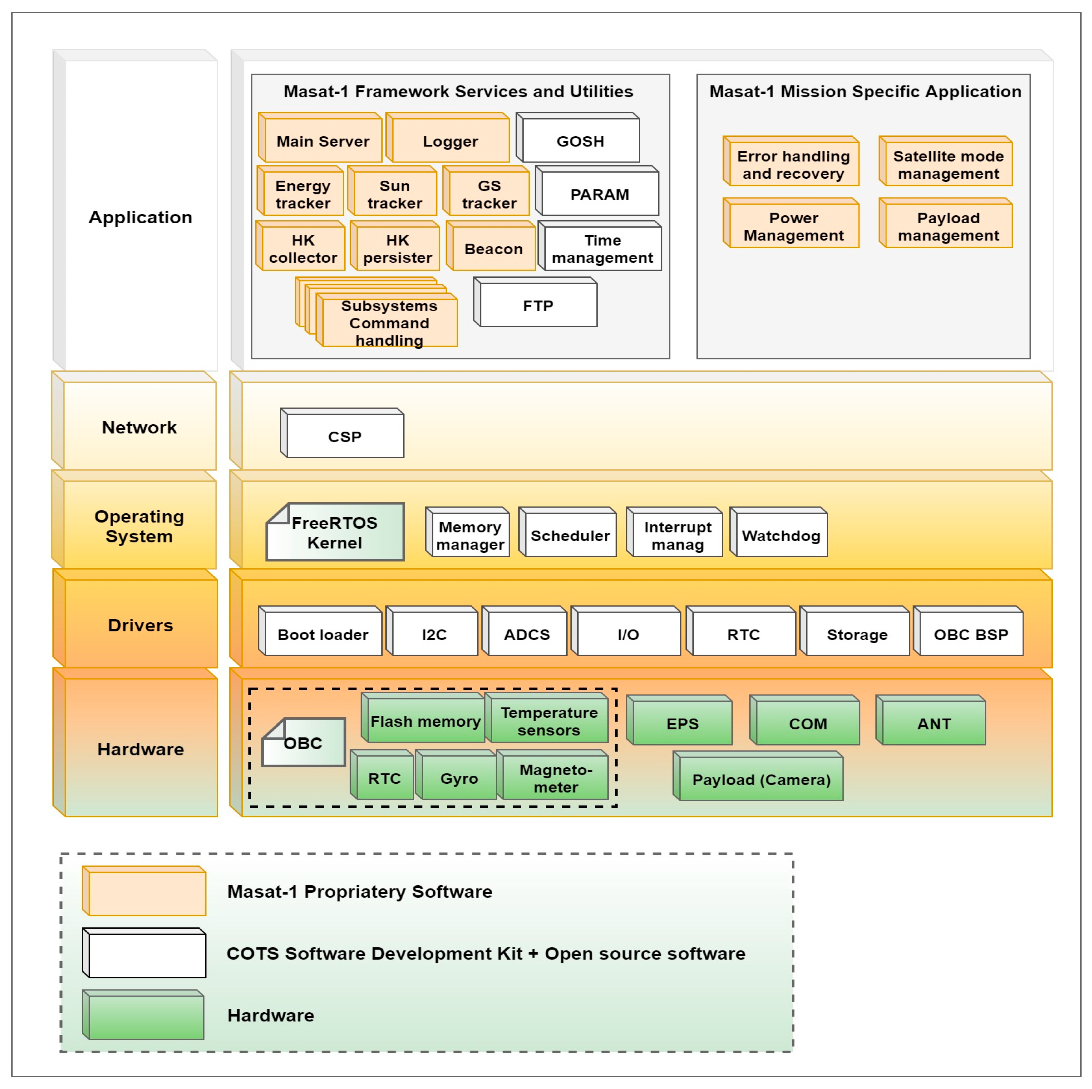
7. Masat-1 Flight Software Architecture Design and Implementation

As stated in Section 5, the Masat-1 software architecture main goals are modularity (Q1), reliability (Q2), re-usability (Q3) and extensibility (Q4). To ensure the traceability of these software qualities, the remaining part of this section will present all the design and implementation choices made regarding Masat-1 software architecture and the application level. Testing approaches and tools are highlighted; any detailed discussion is beyond the scope of this paper. Instead, it will the subject of future works.
Masat-1 flight-control software follows a layered architecture to encapsulate different abstraction levels as it is shown in Figure 12. Each layer functionality is divided into modules, while each module encapsulates a set of functionalities. In this design, a clear distinction was made between the generic platform services such as: the housekeeping data collection and persisting, command handling and scheduling, etc. and specific mission functions. Moreover, the operating system, drivers and hardware can be changed by design since they are abstracted from the application code thanks to the network layer. Therefore, this layered architecture satisfies Q1, Q3 and Q4 and enhances the system portability. The following sections each describe a layer with a special focus on the detailed design aspects of the application layer.

7.1. Drivers Layer

This layer encapsulates all the hardware-dependent software developed by manufacturers to interact with the hardware modules and peripherals. The set of functionalities supported at this level are the real-time clock, data storage system, Board Support Package (BSP), and drivers for external items such ADCS actuators and sensors.

7.2. Operating System Layer
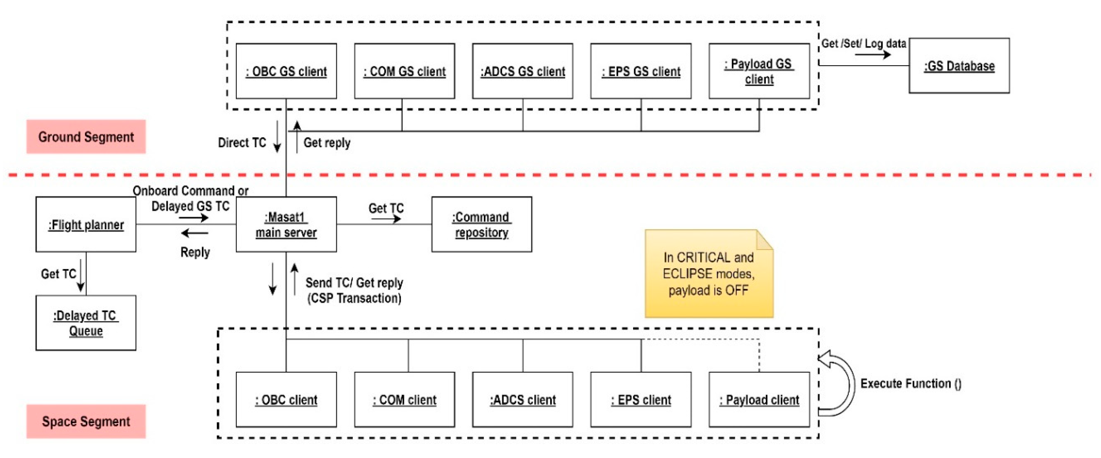
The operating system uses lower layers’ functionalities to provision high level features for upper layers, such as: multi-tasking, message queues, timers, and synchronization structures, so that mission-dependent functionalities are easily implemented or modified regardless of the underlying platform.
When developing the Masat-1 software, two operating systems were used: GNU/Linux and FreeRTOS; GNU/Linux was used during the software development and simulation phase. It will also enable the eventual support of powerfully embedded computers such as ARMTM Cortex and Raspberry Pi in subsequent missions. This would eventually ensure the reuse of Masat-1 software on different platforms and thus, enhance the requirement Q3. Then, the software was ported to FreeRTOS to enable onboard real-time management while using a small footprint. Besides, it is more adequate for low-power applications running in small-scale missions such as Masat-1. To achieve complete software portability, we intend to eventually include abstraction functionalities in the network layer, where both operating systems’ basic functionalities are mapped to a common API. For instance, to create a task, TaskCreate() function will be a wrapper to xTaskCreate() in FreeRTOS and to pthread_create() in Linux.

7.3. Network Layer

This layer abstracts the lower layer from the application layer where the uniform APIs using the Cubesat space protocol (CSP) are provided to access services and resources. Cubesat space protocol (CSP) is a small network layer protocol, open source written in GNU C. Its implementation is designed for both desktops and embedded systems such as the AVR- and ARM-based modules. This is currently ported to FreeRTOS, Posix OS, MacOS and Windows. Thus, not only is it facilitating cross-platform data exchange when using different COTS modules, but it will also enable abstraction of lower layers from Masat-1 application layer, hence fulfilling Q3 and Q4.
CSP design follows the TCP/IP model and includes a router, a socket buffer pool and a connection-oriented/connectionless socket API. As a result, communication among implemented tasks and services involves simple invocations and data passing using a CSP packet structure, which encapsulates the necessary network-layer information in a 32-bit header.

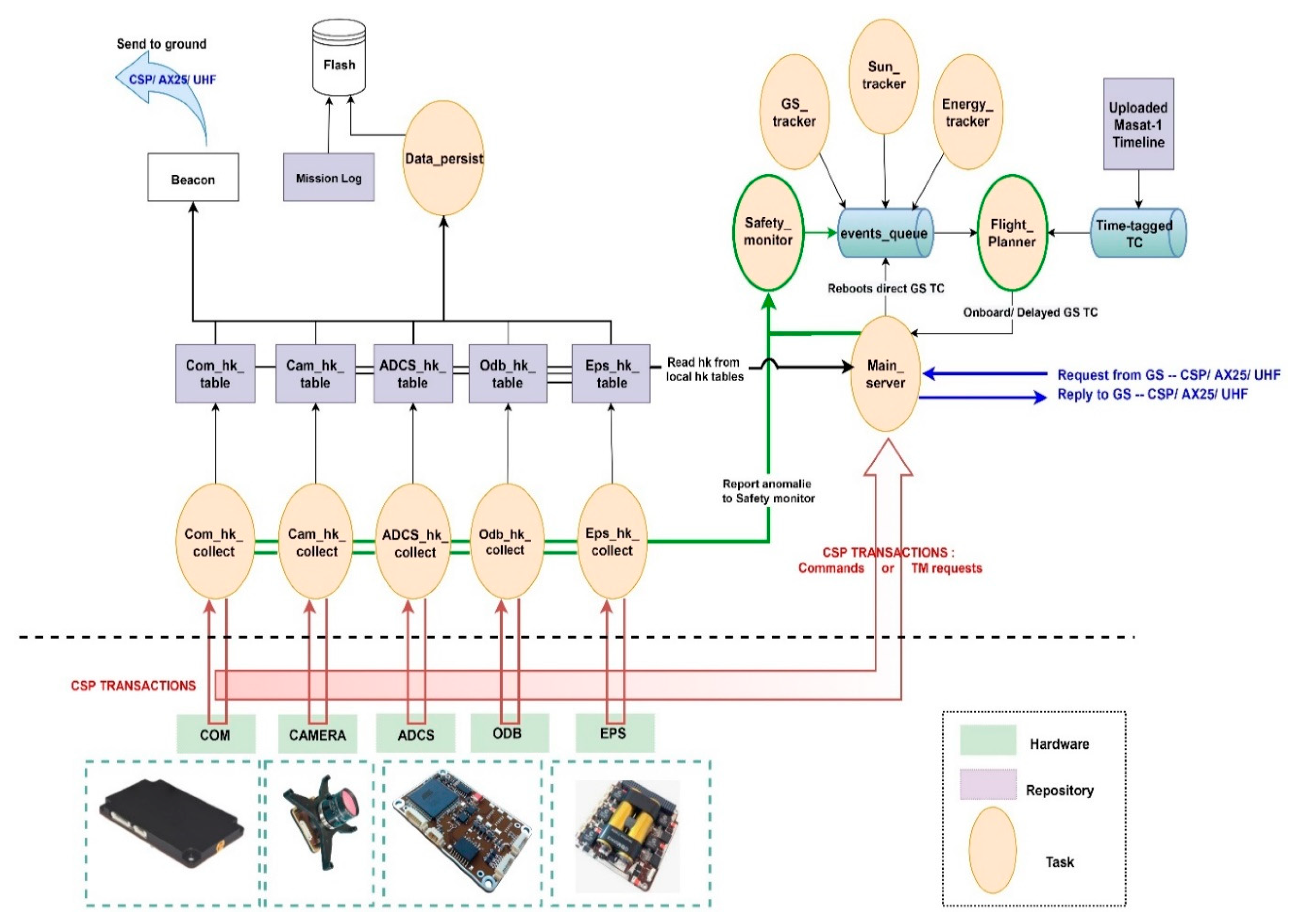
7.4. Application Layer

To further enhance Masat-1 software architecture modularity (Q1), we adopted a service-oriented pattern coupled with a finite state machine to execute Masat-1 mission functionalities in a deterministic manner. Moreover, every functional requirement was broken into well defined modules and concurrent tasks with simple interfaces and uniform APIs to communicate messages in the form of commands and requests. This messaging system was based on a client–server model, and it relies on CSP networking infrastructure. This enabled efficient inter-process and inter-node communication. This approach provided an intuitive way to implement Masat-1 functional requirements in a modular manner, where each task handles a particular functionality in a loosely coupled manner. For instance, to provide the onboard and ground monitoring of Masat-1 health state during its lifetime, the onboard software must be able to collect and persist onboard housekeeping data periodically. As it is depicted in Figure 13, dedicated collector tasks ensure these functionalities for each subsystem. Housekeeping data are collected from all subsystems using uniform CSP interfaces. Furthermore, housekeeping data are saved in tables to provide ground operators with immediate and easy access to housekeeping data. To keep these tables updated and readily available at all times, housekeeping collector tasks run periodically; then, a “Persistor” task saves the data to a binary file in the Flash memory. The service-oriented architecture enables requirements/functionalities encapsulation in services/commands, hence ensuring a modular design of the Masat-1 command system. These services are data structures containing all the necessary information to execute the target code, such as function handlers and data parameters; and they are invoked using uniform API thanks to CSP messaging system. All commands are stored in “Masat-1 services repository”, and they are identified by the target system node and a numerical ID. Moreover, their implementation is specific and independent; thus, command functional testing can be carried out separately. In this manner, services/commands can be easily added, removed or modified. Also, neat separation between mission generic and specific services can be achieved.
The architecture core modules are the main server, flight planner and the clients because they implement the command execution logic, which is illustrated by the UML communication diagrams in Figure 14. Packets are received using the main server task. When a CSP packet is received, its HMAC key validity is checked; the software should process and execute ground commands after authenticating their source and rejecting any invalid or illegal packets. This is to protect the satellite against any misuse. If the packet is valid, then it is either directly executed, where a direct message is sent to the adequate client using a CSP transaction, or it is added to a priority queue. Certain commands need to be executed at a time when the satellite is out of the control station range. To enable this type of event scheduling, commands are stored in a priority queue of delayed commands and executed at the specified time/event. Thereafter, the flight planner can pop commands to be processed one at a time during the Sun-Vis mode only when enough power is available for any mission-related maneuvers. It is worth mentioning that direct commands received from GS have the priority over delayed TCs. Finally, the main server calls the adequate function to generate command and requests to be sent as CSP messages to subsystems clients, and it increments several telemetry points, such as counters of valid and invalid received packets. In summary, enhancing the flight software modularity (Q1) will intrinsically ensure its reusability (Q3), extensibility (Q4) and flexibility to any further design modifications, thus supporting the incremental and recursive development of Masat-1 flight software.
On the other hand, to mitigate outer space risks and ensure reliability (Q2), several features were added to the software since hardware design changes and redundancy are off the budget of the Masat-1 project. Subsequently follows a discussion of the most notable of these features.
  • Architectural choices: Masat-1 flight software architecture pattern contributed to Masat-1 overall reliability by increasing system robustness through the loose coupling of modules and services. Additionally, a finite state machine was implemented at the level of the flight planner to manage Masat-1 operations in a deterministic manner. It also offered a simple and clean implementation of the control logic of the spacecraft.
  • Defensive programming: our solution was implemented in the C language using a defensive programming approach to develop a deterministic flight software with predictable behavior despite the unexpected user/event inputs. This also enhanced software bug detectability and isolation.
  • Event logging includes errors/failures reporting and the logging of important operations, such as packet events, queues or housekeeping data-persisting files creation/deletion after a reboot, etc. Distinct text files were used to differentiate between these events. Readable text files were used instead of binary files to facilitate the tracking of onboard operations and errors/failures in a timely manner. Besides, error logging was very helpful during software debugging and testing.
  • Fault-tolerance
    • Hierarchical FDIR architecture: several levels of faults are defined from units up to the mission/system level (Table 6). The “flight planner” that is the highest FDIR level is in charge of the execution of vital functions/ground commands to ensure the spacecraft integrity and safety; while lower level hierarchies, namely the “safety monitor” and the “housekeeping collectors” are responsible for errors/faults detection in the subsystem and component levels. Therefore, the Masat-1 FDIR hierarchical system is at the same time centralized and distributed: centralized as the on-board fault tolerance decisions are made at a single location, at the level of the flight planner. It is distributed in a sense that each subsystem implements part of the overall FDIR architecture by mapping FDIR functions versus the hardware and/or software safety functions. This concept allows the reuse of the centralized part and the decoupling of the FDIR levels; thus, enhancing system fault management modularity.
      To monitor the system health and detect anomalies, several detection methods depending on the type of errors/failures were implemented. Here, we present some of them: units’ internal health checks are easy to perform thanks to the units’ housekeeping data and events raised by built-in safety functions. These provided the health status reporting, and they will be sent to the ground for further analysis. They will also be used on-board to raise a local alarm. This detection method is applied mostly to monitor on-board sensors and actuators. Data transmission checks aim at detecting protocol communication anomalies. For example, received commands’ node and ID numbers are checked against “Masat-1 services repository”. If no match is found, the command is dropped, and the error is reported in the error events log. This concerns all the items connected to the CSP network. Consistency checks concern the data values monitoring. Two techniques were considered: the first one was rule-based limit checks to monitor the measures provided by a sensor or an actuator. For instance, if the values provided by temperature sensors of the EPS are consistently lower than a certain threshold, the heating system will be activated automatically. The second one is command consistency; onboard routines were implemented to verify the right execution of a given command. In a default case, a number of command retries is issued. After the failure of all attempts, the error is reported in the log, and an alarm is raised to higher FDIR levels. Therefore, quick detection time and efficient decision making are key factors during a failure scenario. Furthermore, important sensor data, such as voltages, currents, temperatures and orbit and attitude parameters are collected periodically and sent to the ground to be checked for safe operations. Other detection techniques include the periodic checks of flags for running tasks and periodic pinging to subsystems. For example, the OBC is a single point failure in Masat-1-centralized architecture. To mitigate this weak point, we used external watchdogs in the EPS to monitor the OBC’s well functioning. Periodic pings are sent; in case of any anomaly, after five failing pings, the EPS will reset the OBC, and the COM will send its own telemetry only to GS in a periodic beacon during the communication window. We used the same strategy to detect communication failures with the ground; if no packet is received within a predefined period from the ground, a local “RX idle timer” is set to reinitialize the receiver configuration. If the failure persists, an external watchdog in the EPS will induce the complete system reset. Periodic pinging and periodic checks of flags are especially useful to detect software errors/faults induced by single events upsets. They both rely on watchdog timers to monitor SW/HW items well functioning.
      Upon the detection of anomalies, events are raised and are handled through a decision matrix (event/action correlation) implemented at the level of the “safety monitor”. For failures at the subsystem or system level, the safety monitor sends signals to the flight planner to switch to safe mode. This mode was implemented to maintain the spacecraft in a safe-guarding configuration when major anomalies occur, and it will remain in this state until next contact with the ground segment. Indeed, a fail-safe approach was selected instead of the safe-to-fail approach to design the Masat-1 FDIR system due to lack of hardware. During safe mode, all non-vital onboard units and subsystems are powered off to conserve power. The spacecraft shall also be pointing to nadir—ideally, while maintaining an attitude that is thermally safe and energetically optimal.
    • Parameter defaulting: before launch, all Masat-1 parameters and settings are stored in “a boot-file” and “a default-file”. Both configurations are maintained in a local non-volatile memory of each subsystem for more resilience against SEU events. Unlike the boot-file, the default-file cannot be modified on orbit. This is to provision a valid backup configuration; upon first the startup or reboots, the system configuration of each module is read from the boot-file, and it can be easily modified by command. If, for some reason, the system parameters are out of range or in case of anomalies, the satellite is restored back to a valid state thanks to the backup configuration.
    • Protected variables: some variables are critical for the operation of the satellite. An example of these parameters is the encryption key, which is used for the authentication of communication with the ground, or the antenna deployment status. In fact, any run time modification of these parameters due to SEU events such as bit flips might jeopardize the mission. Therefore, the identification and persisting of these parameters is crucial.
  • System Reconfigurability: the Masat-1 parameter system enables the easy reconfiguration and calibration of the system without lengthy software upload. Besides, all commands accept a wide range of inputs, thus enhancing the commanding system flexibility. In addition, the parameters ruling Masat-1 operations can be easily changed to fit in-orbit behavior. For instance, beacon periods can be adjusted depending on the power available on-board; the collection and persisting rates can be modified; moreover, the parameter system enables operators to change the radio basic settings to optimize its operation for better link reliability and performance.
  • Throughout software validation and verification (V&V) testing: this is based on white box and integration testing. White box unitary testing will be applied to each command, since they are called independently as APIs or services provided to the ground segment. Integration tests are mini-applications running operation scenarios, such as switching the spacecraft through various states by generating events, running a command with different parameters, simulating failures scenarios, etc. This is to verify that the flight software is running in a deterministic manner and finishing tasks within specified deadlines. If an abnormal output or behavior in the software is identified, it will be fixed, and tests are repeated again. When integrated in its end environment, the overall reliability of the flight-control software is assessed using functional validation testing all within SIL and HIL simulations on a virtual model of each subsystem. Hardware–software interaction analysis (HSIA) will be used to analyze flight software reactions to hardware failures. It is worth mentioning that we also intend to use this V&V testing campaign to identify all failure modes that were unaccounted for during FMECA analysis. In such cases, the FMECA will be updated, the effects of new failure modes induced by these modifications will be evaluated, and adequate preventive/corrective functions will be implemented.

8. Conclusions

Cubesats have emerged as a cost-efficient ticket to reach space thanks to mission budgets downscaling by means of form factor standardization and the incorporation of agility in development processes. Cubesats have enabled actors with limited experience far beyond large space agencies, such as universities, to successfully undertake Cubesat programs despite the limited infrastructure available. However, this flexibility increased the inherent risks commonly faced in aerospace missions. To mitigate these risks, it is crucial to design and develop reliable hardware and flight software architectures. Following ad hoc design approaches would only increase these risks. Therefore, our methodology is based on a recursive and iterative system engineering approach applied throughout the mission design life cycle within a custom-tailored ECSS framework. Moreover, our approach revolves around developing a reliable hardware architecture in a timely manner using COTS modules with extensive flight heritage while focusing all efforts on implementing a simple, yet reliable software solution that verifies important quality criteria, namely modularity, reliability, reusability and extensibility. This is to establish a solid framework for subsequent missions’ development.
To define the scope of the flight software design and ensure the simplicity of the solution, mission autonomy level E2 has been selected according to the ECSS-E-ST-70-11C standard; hence, Masat-1 mission execution will be mainly under ground control, and only limited on-board intelligence is implemented. Similarly, fault isolation and management autonomy level F1 has been chosen; given Masat-1 mission objectives and design constraints, spacecraft recovery is more of paramount importance than mission follow-on Thus, as per the fail-safe approach, simple FDIR strategies and techniques were considered to lead the Cubesat to its safe mode after a failure while waiting for ground intervention. To efficiently implement FDIR functions, the evaluation of Masat-1 mission risks is necessary. Possible failure scenarios were defined using functional FMECA analysis, a top-down systematic approach as per ECSS guidelines. As a result, a key lesson was learned; provided it is a timely and an iterative activity, functional FMECA can be an effective tool during flight software requirement elicitation, and designing decision-making processes, and any late implementation or restricted application of the FMECA drastically limits its use. The findings of the RBD and FMECA analysis revealed that the EPS, ADCS system and the flight-control software were the most critical items. Moreover, Masat-1 RBD analysis results demonstrated that using redundancy techniques might enhance the system reliability. However, implementing hardware redundancies is not a feasible option in the case of the Masat-1 mission. Despite the fact that these findings might be overestimated/underestimated due to possible inaccuracy in the results of the FMECA qualitative approach and due to the lack of quantitative reliability in the data of COTS modules, they have revealed the most important contributors to major potential failures with significant effects on the Masat-1 mission. They also corroborate with statistical data reported in similar Cubesat missions. That being said, a feasible strategy to ensure Masat-1 mission overall reliability was devised. It relies on using, among others:
  • A modular hardware architecture based on COTS modules with extensive flight heritage in conjunction with rigorous functional and system integration testing; modularity shall increase the system reliability because it enhances errors/failures isolation.
  • Defensive programming to develop a deterministic flight software with predictable behavior despite unexpected user/event inputs. This will also enhance software bugs detectability and isolation.
  • A modularflight software architecture: a layered service-oriented pattern coupled with CSP network infrastructure was used to ensure a modular and loosely coupled architecture. Furthermore, the control logic of the spacecraft is based on a finite state machine implemented at the application layer. When coupled with a closed mode CONOPS, this will ensure the deterministic behavior of the spacecraft.
  • Fault management techniques such as a hierarchical FDIR architecture. FDIR functions were implemented at the system and subsystem levels to lead the spacecraft to its safe mode after a software failure or/and minor hardware faults, while waiting for ground intervention.
  • Throughout software V&V using white box unitary and integration testing. When integrated in its end environment, the overall reliability of the flight-control software is assessed using functional validation testing all within SIL and HIL simulations. Hardware Software Interaction Analysis (HSIA) might be used to analyze flight software reactions to hardware failures. This way, the V&V testing campaign will also help compensating for drawbacks of functional FMECA and possible inaccuracies of RBD results. Indeed, exhaustive testing will help identifying all unforeseen failure modes that might emerge during Masat-1 operational phase in-orbit. In such cases, the FMECA will be updated, effects of new failure modes induced by these modifications will be evaluated, and adequate preventive/corrective functions will be implemented. This process will continue even after satellite launch. This way, statistical data about the nature of any potential failures detected in orbit and their causes are accumulated, and the lessons learned built upon them will contribute to further enhancement of subsequent missions’ overall reliability.
This work is our first step towards establishing a solid framework to design and develop a simple, yet reliable and generic flight-control software of a Cubesat. To further enhance subsequent missions’ autonomy and reliability performance in term of the reaction time and flexibility of on-board decisions, future works will focus on (i) investigating hybridized flight-control systems that are based on time-tagged commanding using timelines and event-based onboard-control procedures; (ii) improving the detection and isolation phase of the hierarchical FDIR architecture. Incorporating SW/HW redundancies is also recommended. Further research should also focus on filling open gaps related to the epistemic uncertainty of FMECA risk indexes. The challenge in this sense consists of generating “relevant experimental data (test or field/in-orbit data) for support in the reliability prediction” [9].

Author Contributions

Conceptualization, I.L.; methodology, I.L. and T.R.; software, I.L. and T.R; validation, I.L., T.R. and A.H.; formal analysis, I.L.; anomaly investigation, I.L.; resources, I.L, T.R. and M.K.; writing—original draft preparation, I.L.; writing—review and editing, I.L. and T.R.; supervision, T.R. and M.K.; project administration, M.K.; funding acquisition, M.K. and T.R. All authors have read and agreed to the published version of the manuscript.

Funding

This research is supported by the CNRST under grant PPR/2015/12, and the APC was funded by the first author, Ms. Ibtissam Latachi.

Conflicts of Interest

The authors declare no conflict of interest.

References

  1. Latachi, I.; Rachidi, T.; Karim, M.; Hanafi, A. Building Low Cost CubeSat: Guidelines and Design Approach; Univelt, Inc.: Escondido, CA, USA, 2018; Volume 163. [Google Scholar]
  2. Hanafi, A. Etude et Conception du Segment Spatial du Nanosatellite Universitaire Masat-1 Avec Ordinateur de Bord Secondaire Reconfigurable à Base de FPGA. Ph.D. Thesis, Université Sidi Mohammed Ben Abdellah, Fez, Morocco, October 2017. [Google Scholar]
  3. Available online: https://www.nanosats.eu/ (accessed on 21 January 2020).
  4. Eickhoff, J. Onboard Computer, Onboard Software and Satelllite Operations; Springer: Berlin/Heidelberg, Germany, 2012. [Google Scholar]
  5. Nieto-Peroy, C.; Emami, M.R. CubeSat Mission: From Design to Operation. Appl. Sci. 2019, 9, 3110. [Google Scholar] [CrossRef] [Green Version]
  6. Langer, M. Reliability Assessment and Reliability Prediction of CubeSats through System Level Testing and Reliability Growth Modelling. Ph.D. Thesis, Technische Universität München, Munich, Germany, 2018. [Google Scholar]
  7. ESA-ESTEC, ECSS-Q-ST-30-02-C. In Space Product Assurance—Failure Modes, Effects and Criticality Analysis (FMEA/FMECA); ESA-ESTEC: Noordwijk, The Netherlands, 2009.
  8. Gelmi, S. Fault Detection Isolation and Recovery for LUMIO mission: Algorithm and methodology. Master’s Thesis, Delft University of Technology, Delft, The Netherlands, 2019. [Google Scholar]
  9. ESA. Effective Reliability Prediction for Space Applications. 2016. Available online: https://www.reliability.space/app/download/14847209524/ESA_WhitePaper_2016.pdf?t=1518002321. (accessed on 30 September 2020).
  10. PC/104 Embedded Consortium, “PC/104 Specification—Version 2.6,” 13 October 2008. Available online: https://pc104.org/wp-content/uploads/2015/02/PC104_Spec_v2_6.pdf (accessed on 13 September 2020).
  11. ECSS-E-ST-70-11C. In Space Engineering—Space Segment Operability; ESA-ESTEC: Noordwijk, The Netherlands, 2008.
  12. Gessner, R.; Kösters, B.; Hefler, A.; Eilenberger, R.; Hartmann, J.; Schmidt, M. Hierarchical FDIR Concepts in S/C Systems. In Proceedings of the Space OPS 2004 Conference; American Institute of Aeronautics and Astronautics (AIAA), San Diego, CA, USA, 28−30 September 2004. [Google Scholar]
  13. Wander, A.; Förstner, R. Innovative fault detection, isolation and recovery on-board spacecraft: Study and implementation using cognitive automation. In Proceedings of the 2013 Conference on Control and Fault-Tolerant Systems (SysTol), Nice, France, 9−11 October 2013; pp. 336–341. [Google Scholar]
  14. Xavier, O. FDI(R) for satellites: How to deal with high availability and robustness in the space domain? Int. J. Appl. Math. Comput. Sci. 2012, 22, 99–107. [Google Scholar]
  15. Shummer, F. Reliability Assessment of Small Spacecraft Before Launch. 2017. Available online: https://www.researchgate.net/publication/334132239_Reliability_Assessment_of_Small_Spacecraft_Before_Launch (accessed on 11 September 2020).
  16. Birolini, A. Reliability Engineering; Springer Science and Business Media LLC: Berlin, Germany, 2010. [Google Scholar]
  17. NASA. Fault Tree Handbook with Aerospace Applications. 2002. Available online: http://www.mwftr.com/CS2/Fault%20Tree%20Handbook_NASA.pdf. (accessed on 14 September 2020).
  18. Shafiee, M.; Enjema, E.; Kolios, A. An Integrated FTA-FMEA Model for Risk Analysis of Engineering Systems: A Case Study of Subsea Blowout Preventers. Appl. Sci. 2019, 9, 1192. [Google Scholar] [CrossRef] [Green Version]
  19. Rausand, M.; Barros, A.; Hoyland, A. System Reliability Theory—Models, Statistical Methods, and Applications, 2nd ed.; John Wiley & Sons: Hoboken, NJ, USA, 2020. [Google Scholar]
  20. Department of Defense, USA, Mil-Std-1629a-Military Standard—Procedures for Performing, a Failure Mode, Effects and Crltlcalliv Analysis. 24 November 1980. Available online: https://www.fmea-fmeca.com/milstd1629.pdf. (accessed on 13 September 2020).
  21. Stesina, F.; Corpino, S. Investigation of a CubeSat in Orbit Anomaly through Verification on Ground. Aerospace 2020, 7, 38. [Google Scholar] [CrossRef] [Green Version]
  22. Shiotani, B. Reliability Analysis of Swampsat. 2011. Available online: https://ufdc.ufl.edu/UFE0043397/00001 (accessed on 17 January 2020).
  23. Menchinelli, A.; Ingiosi, F.; Pamphili, L.; Marzioli, P.; Patriarca, R.; Costantino, F.; Piergentili, F. A Reliability Engineering Approach for Managing Risks in CubeSats. Aerospace 2018, 5, 121. [Google Scholar] [CrossRef] [Green Version]
  24. Li, J. Reliability Comparative Evaluation of Active Redundancy vs. Standby Redundancy. Int. J. Math. Eng. Manag. Sci. 2016, 1, 122–129. [Google Scholar] [CrossRef]
  25. Jacklin, S.A. Small-Satellite Mission Failure Rates; Nasa Ames Research Center: Mountain View, CA, USA, 2019. [Google Scholar]
  26. Tafazoli, M. A study of on-orbit spacecraft failures. Acta Astronaut. 2009, 64, 195–205. [Google Scholar] [CrossRef]
  27. Asundi, S.A.; Fitz-Coy, N.G. Design of command, data and telemetry handling system for a distributed computing architecture CubeSat. In Proceedings of the 2013 IEEE Aerospace Conference, Big Sky, MT, USA, 2–9 March 2013; pp. 1–14. [Google Scholar]
  28. Latachi, I.; Karim, M.; Hanafi, A.; Rachidi, T.; Khalayoun, A.; Assem, N.; Dahbi, S.; Zouggar, S. Link budget analysis for a LEO cubesat communication subsystem. In Proceedings of the 2017 International Conference on Advanced Technologies for Signal and Image Processing (ATSIP), Fez, Morocco, 22–24 May 2017; pp. 1–6. [Google Scholar]
Figure 1. Nanosatellites launched by organizations as of 21 April 2020 [3].
Aerospace 07 00146 g001
Figure 2. Masat-1 mission design approach [1].
Aerospace 07 00146 g002
Figure 3. Masat-1 main bus architecture overview.
Aerospace 07 00146 g003
Figure 4. Fault detection, isolation and recovery (FDIR) process in ECSS Standards.
Aerospace 07 00146 g004
Figure 5. EPS reliability block diagram (RBD).
Aerospace 07 00146 g005
Figure 6. Antenna system reliability block diagram.
Aerospace 07 00146 g006
Figure 7. ADCS reliability block diagram.
Aerospace 07 00146 g007
Figure 8. OBC reliability block diagram.
Aerospace 07 00146 g008
Figure 9. COM reliability block diagram.
Aerospace 07 00146 g009
Figure 10. Masat-1 concept of operations (CONOPS).
Aerospace 07 00146 g010
Figure 11. Masat-1 INIT mode.
Aerospace 07 00146 g011
Figure 12. Top-level building layers and modules of Masat-1 flight-control software.
Aerospace 07 00146 g012
Figure 13. Masat-1 flight software high-level architecture.
Aerospace 07 00146 g013
Figure 14. Masat-1 UML communication diagram.
Aerospace 07 00146 g014
Table 1. Chosen autonomy level regarding (a) mission operations and (b) fault management for Masat-1 mission, according to the European Cooperation for Space Standardization (ECSS) standards [11].
(a) Mission Operations Autonomy Levels According to ECSS-E-ST-70-11C
LevelDescriptionFunctions
E1Mission execution under ground control; limited on-board capability for safety issues• Real-time control from ground for nominal operations
• Execution of time-tagged commands for safety issues
E2Execution of pre-planned, ground-defined, mission operations on-board• Capability to store time-based commands in an on-board scheduler.
E3Execution of adaptive mission operations on-board• Event-based autonomous operations
• Execution of on-board operations control procedures
E4Execution of goal-oriented mission operations on-board• Goal-oriented mission re-planning.
(b) Failure and Fault Management Autonomy Levels According to ECSS-E-ST-70-11C
LevelDescriptionFunctions
F1Establish safe space segment configuration following an on-board failure• Identify anomalies and report to ground segment
• Reconfigure on-board systems to isolate failed equipment or functions
• Place space segment in a safe state
F2Re-establish nominal mission operations following an on-board failure• As F1, plus reconfigure to a nominal operational configuration
• Resume execution of nominal operations
• Resume generation of mission products
Table 2. (a) (Top)—severity level for each dependability effect; (b) (bottom)—probability levels.
(a)
Severity CategorySeverity Number (SN)Impact
Catastrophic4Total mission failure.
Critical3Partial loss of subsystems’ services, and recovery is not possible.
Mission is partially compromised.
Major2One or many subsystems/processes are affected by the unit fault/failure, but recovery is possible.
Minor/major degradation in mission performance.
Minor1No vital subsystem/process is affected by the unit fault/failure.
(b)
Likelihood of OccurrenceProbability Level (PN)
Probable: Custom SW/HW components with no space heritage, or failure mode probability is high as it occurred in almost every similar mission.4
Occasional: Custom SW/HW components and COTS with little space heritage, or failure mode probability is moderate as it occurred many times in similar missions.3
Remote: COTS with little space heritage, or failure mode probability is low as it occurred once or twice in similar missions.2
Extremely Remote: COTS with considerable space heritage, or failure mode probability is extremely low as it has never been experienced in similar missions.1
Table 3. Criticality matrix: severity level for each dependability effect, derived from [5].
Severity CategorySNsProbability Level
10−510−310−11
PNs
1234
Catastrophic4481216
Critical336912
Major22468
Minor11234
Table 4. Reliability analysis results.
SubsystemNon-RedundancyRedundancyReliability Growth through Redundancy %
ADCS0.59040.64956.56%
EPS0.59040.64956.56%
COM0.729* Partial: 0.8019
** Full: 0.9265
Partial: 8.1%
Full: 21.9%
OBC0.656Partial: 0.7217
Full: 0.8817
Partial: 7.3%
Full: 25%
ANT0.8675N/AN/A
* Partial active redundancy—either by sharing the subsystems’ controllers (e.g., OBC and COM) or by using a separate secondary MCU; ** Full redundancy refers to using a separate secondary module in hot/standby mode.
Table 5. Examples of failure mode, effect and criticality analysis (FMECA) analysis for EPS possible failure modes at levels 2 and 3.
Failure ModePotential Impact on:
a. Local
b. Other Subsystems
c. Mission/Satellite
Error/Failure CausesSeverity
(SN)
Probability
(PN)
Criticality
(CN)
Levels 2 and 3: Mission/Satellite
EPS System Failurea. No power supplied
b. Loss of all subsystems
c. Mission failure
• EPS board components failure
• Photovoltaic panels failure
• Batteries failure
• Connections failure
• RBF pin failure
• Deployment switch malfunction
4
4
4
4
3
4
1
2
2
2
3
3
4
8
8
8
9
1
2
EPS Low Powera. Less power available onboard
b. Only vital systems are ON
c. Mission partially compromised; mission lifetime reduction
• Batteries not fully charged
○ Charging voltage level below threshold Vsafe.
○ False battery DoD readings
• Boost converters not provided with enough power
• Battery over discharge due to other subsystems design errors
• ADCS failure

1

3
3

3

3

4

2
1

2

2

4

6
3

6

6
EPS Communication with OBC Failurea. Unable to provide power information to OBC
b. Wrong satellite mode switching
c. Mission performance degradation
• I2C communication error/failure
• EPS control software error/failure
• EPS system failure
• OBC board failure
• Flight software error/failure
3

3

4
4
3
2

2

2
2
3
6

6

8
8
9
Table 6. Examples of EPS possible failure modes at Level 1.
Failure ModePotential Impact on:
a. Local
b. Other Subsystems
c. Mission/Satellite
Error/Failure CausesSeverity
(SN)
Probability
(PN)
Criticality
(CN)
Level 1: Subsystems
Batteries Failurea. Fail to store power
b. No power provided to subsystems
c. Mission failure
• Outgassing
• Explosion
• Battery wirings disconnected
4
4
4
2
1
2
8
4
8
Batteries Overheatinga. Life cycle reduced
b. Decrease in power budget
c. Decrease in mission lifetime
• Short circuit224
Batteries Underheating• Heating system faults224
Photovoltaic Panels Failurea. Fail to produce power
b. Low/no power provided to subsystems
c. Mission partially/totally compromised
• Excessive mechanical loads during launch
• Environmental radiations
4

3
3

4
12

12
EPS Control Software Failurea. Inaccurate power budget estimation
b. Low/no power provided to subsystems
c. Mission partially/totally compromised
• Environmental radiations
• Operation failure due to wrong GS commands
• Software bugs
• Electrical failure
3
3

3
4
4
2

1
2
12
6

3
8
EPS Board Failuresa. Fail to distribute power
b. Low/no power provided to subsystems
c. Mission partially/totally compromised
• Burnout due to radiations, overcurrent or out of range temperature.
• Physical damage due to high mechanical load during launch
4


4
2


2
8


8
Table 7. Masat-1 FDIR breakdown: detection techniques and mitigation strategies per level.
Impact of Failure per LevelFault Detection Techniques per LevelFault Recovery Techniques per Level
Level 0:
Units
Unit faults: short currents, overvoltage, over temperature, etc.
No impact on subsystem performance.
Local in unit:
safety measures and watchdogs; log failures to inform ground.
SW/HW built-in safety functions; local correction.
Level 1: SubsystemsMinor failures: errors/faults of units or communication interfaces.
Degraded subsystem performance.
In respective subsystem level: limit checking; diagnosis of housekeeping data, critical parameters controlCommand retry,
log failures to inform ground, and isolate problem;
switch to safe mode.
Level 2 and 3: Satellite and MissionMajor SW/HW subsystem failures: one or more subsystems are affected; partial/total loss of vital subsystems’ services. Anomalies of the OBC module or SW.
Mission is partially compromised in terms of performance or limited operations.
Several alarms from level 0 and 1, faults on FDIR units, hardware alarms or control software alarms.Switch to safe mode;
subsystems reboots.Subsystem reconfiguration.

