Reusable and Reliable Flight-Control Software for a Fail-Safe and Cost-Efficient Cubesat Mission: Design and Implementation
Abstract
:1. Introduction
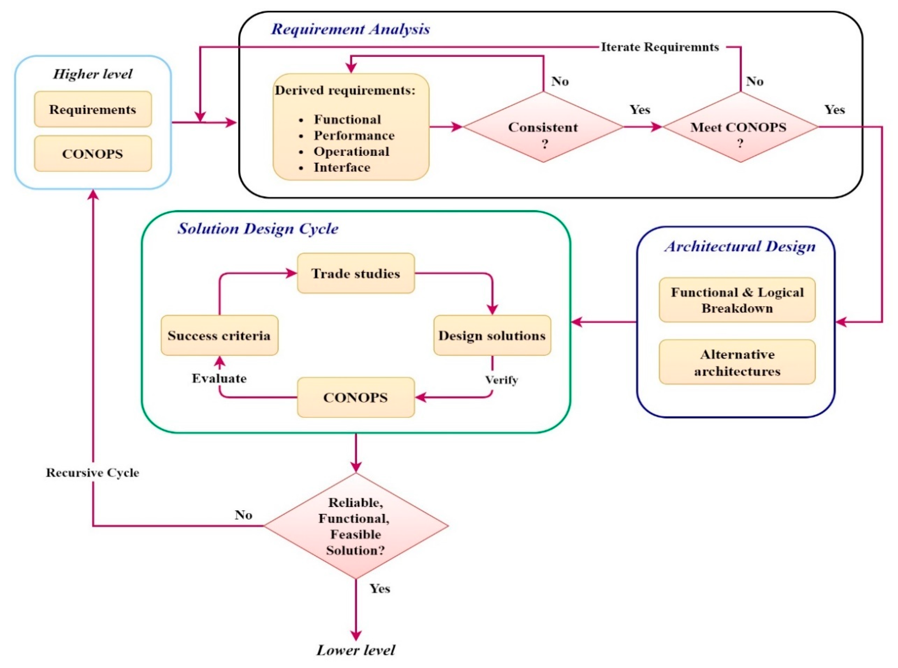
- What design and implementation approach shall we adopt given the Masat-1 mission objectives and design philosophy?
- What concept of operations satisfies Masat-1 requirements; is it open or closed mode?
- What standard risk assessment methods should we use to identify and prioritize the criticalities in the Masat-1 mission design, while considering the absence of accurate quantitative data in the early development phases of the mission?
- Given the Masat-1 mission autonomy levels and the results of mission reliability and risk analysis, what fault tolerance strategies shall we employ to manage Masat-1 mission criticalities in a simple, efficient and low-cost manner?
- Which architecture pattern shall we adopt to ensure the reliability and reusability of onboard flight software?
2. Masat-1 Mission Design Approach
- Develop a reliable bus architecture to withstand outer space harsh environmental conditions that is reusable for subsequent student Cubesat missions;
- Establish a reliable communication link with the control ground station;
- Capture the images of target earth locations using an off-the-shelf high-resolution camera.
3. Masat-1 Mission Overview
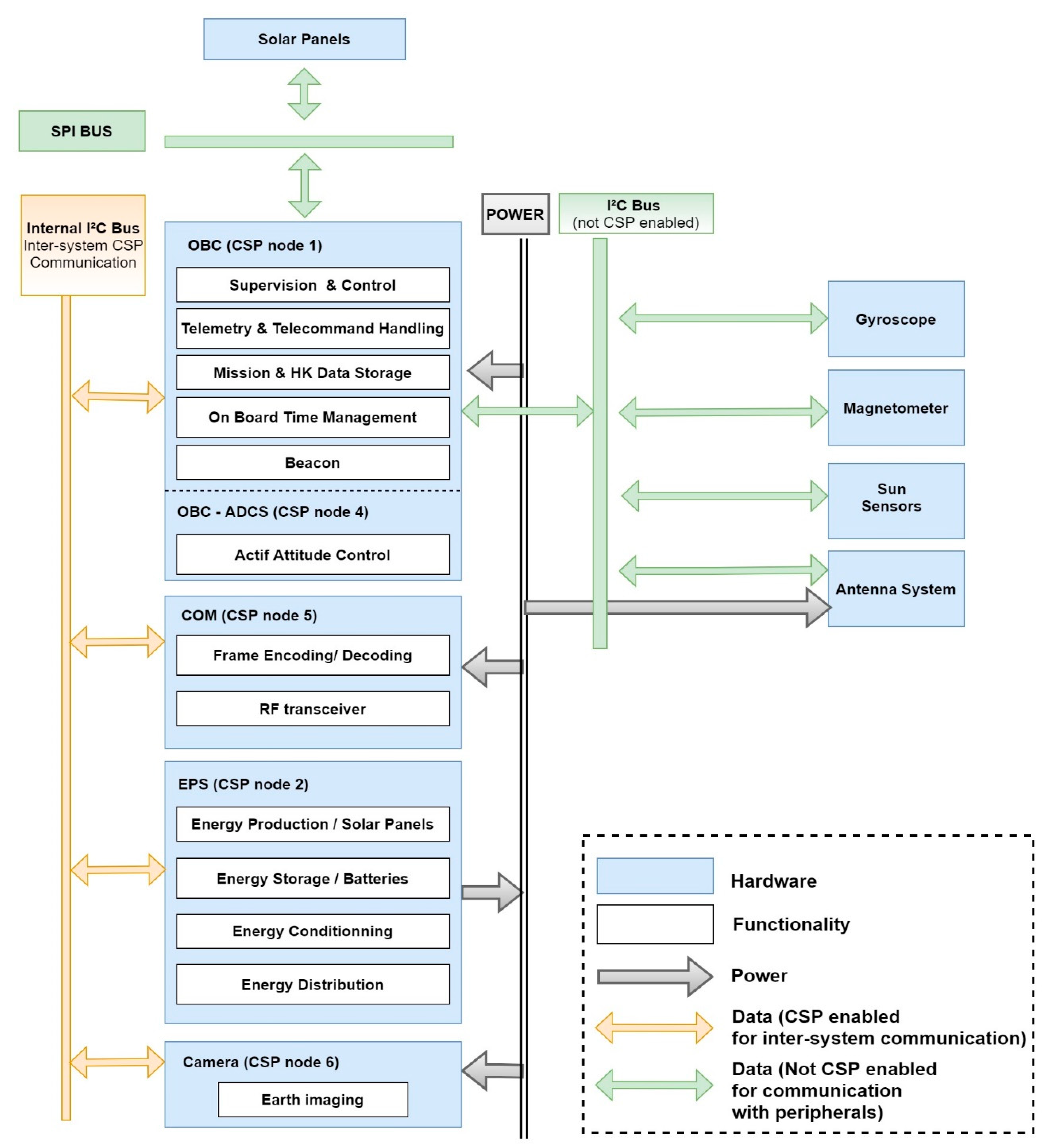
3.1. Masat-1 Mission General Architecture
3.2. Masat-1 Mission Execution Autonomy Levels
4. Masat-1 Mission Fault-Tolerance Management: Concepts and Analysis
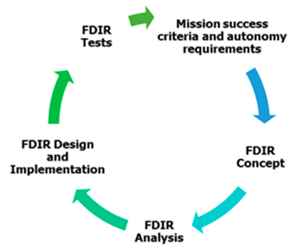
4.1. FDIR Concepts and Strategies
4.2. Failure Mode, Effect and Criticality Analysis (FMECA)
- Step 1
- Provide system schematic diagrams such as reliability block diagrams (RBDs) or system functional diagrams for a system description that is detailed enough to match both the targeted depth of the analysis and the current design maturity;
- Step 2
- Fill out the FMECA worksheet which contains the following elements: all potential failure modes for each functional block of the system, all potential causes of the failure mode (optional), the worst potential consequences locally and on other subsystems, failure detection methods (optional), and methods to prevent or recover from each failure mode. It also assesses the failure criticality number (CN) given the worst potential severity level of the failure (SN) and its probability of occurrence (PN). The severity and probability categories were customized according to Masat-1 requirements and constraints. They are listed in Table 2a,b, respectively. The CN is calculated as the product of the ranking assigned to each factor: CN = SN × PN. It is worth mentioning that combinations of failures are not considered, and each single item failure is assumed to be the only failure in the system [5];
- Step 3
- Define the overall mission critical items list (CIL): an item is critical if its failure mode severity is classified as catastrophic, or if a failure mode CN is greater or equal to 6 in conformance with the criticality matrix (Table 3);
- Step 4
- Define corrective/preventive solutions (such as design provisions or operator actions) necessary to eliminate the failure or to mitigate/control the risk.
4.3. Masat-1 Reliability Block Diagram Analysis
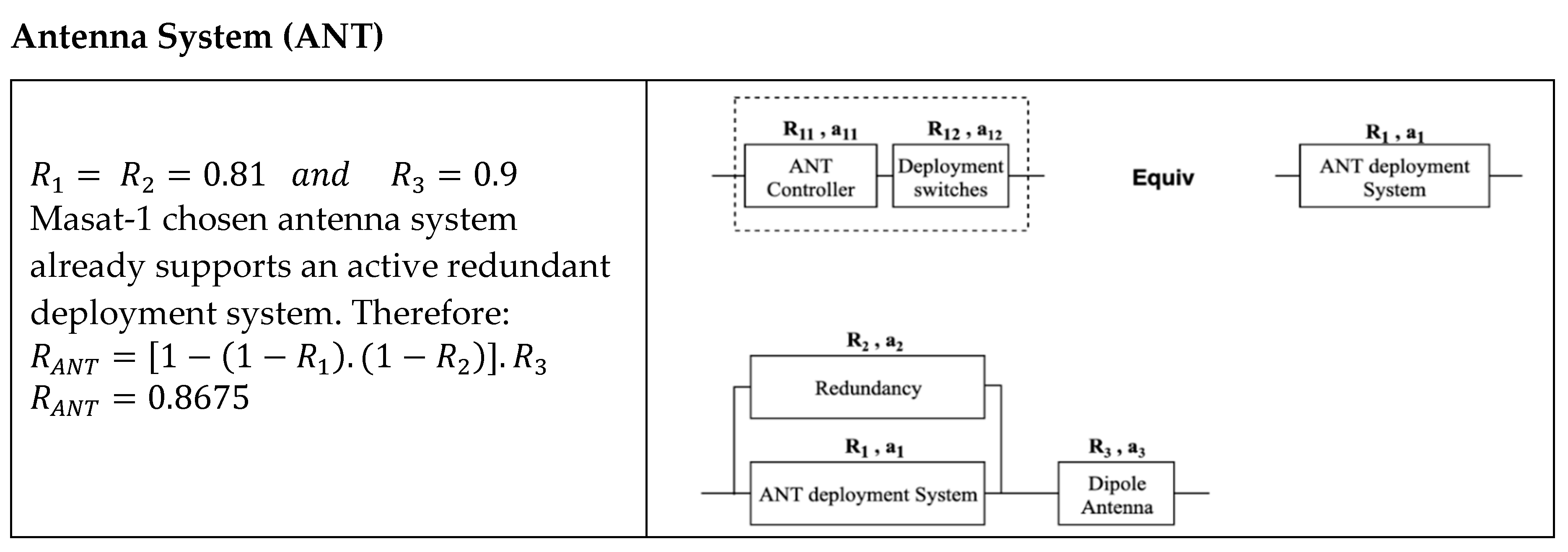
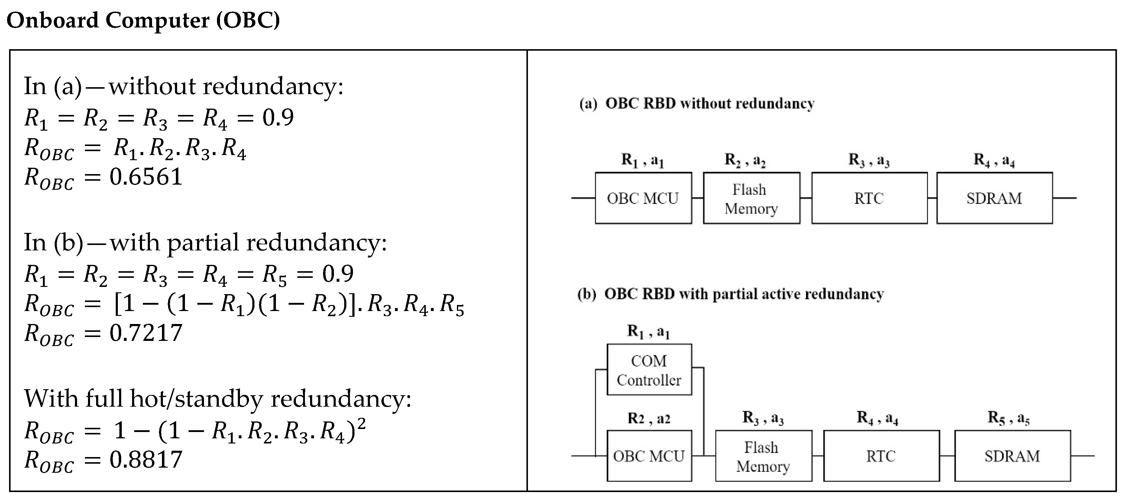
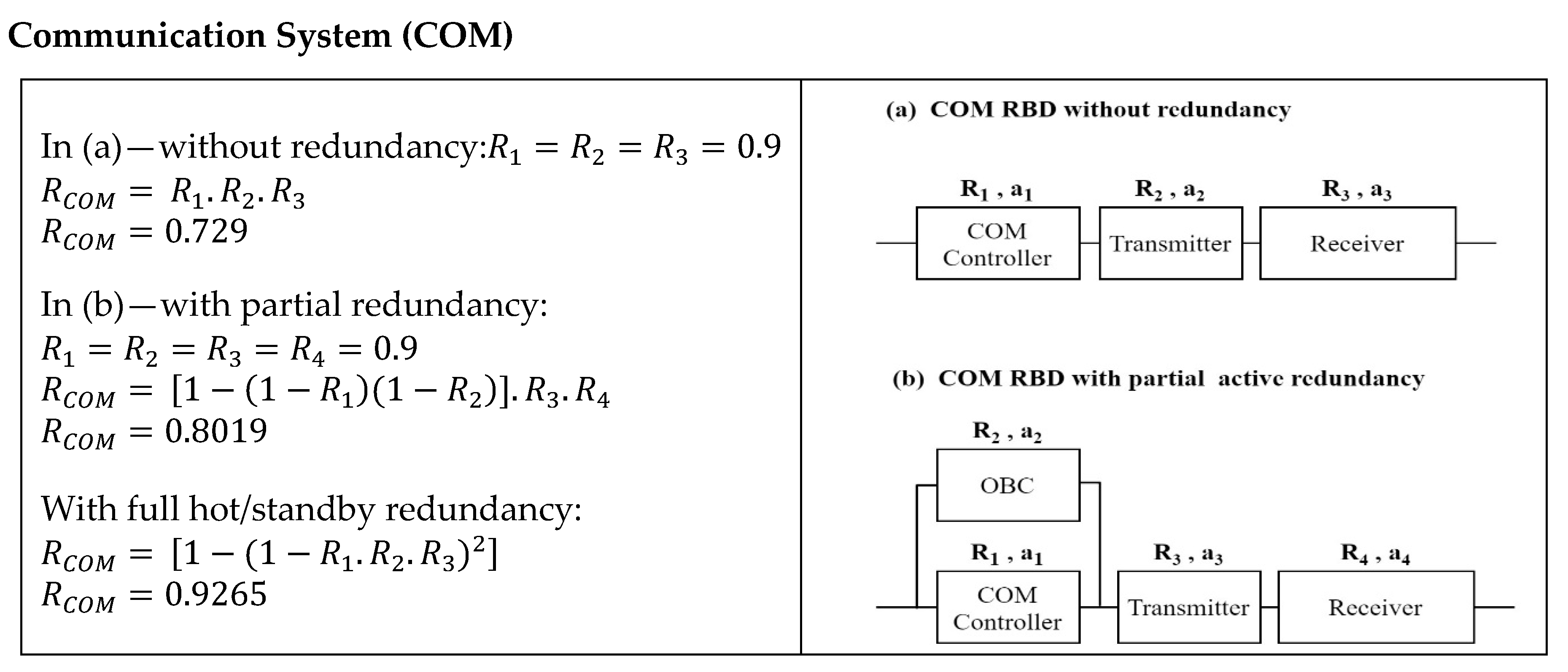
- All parts have a constant failure rate (a(t) = t);
- As we previously mentioned, all parts used in Masat-1 are qualified COTS, from the same manufacturer, with extensive flight heritage in successful missions. Thus, we assumed that they have the same reliability, R = 0.9;
- Thermal and environmental characteristics are not considered; only system architecture is considered for the reliability calculation;
- Major parts such as the controller and the memory are considered to calculate reliability. Connectors and EEE parts such as resistors and diodes are neglected;
- Redundancy switching mechanisms are considered perfect. Therefore, active and hot/standby redundancies are considered the same [24].
4.4. FMECA Results and Discussion
5. Flight-Control Software Requirement Analysis
- Modularity (Q1): in a modular flight software, functionalities related to each component/subsystem are well defined in a separate module. Therefore, modularity shall facilitate the team members’ technical coordination and shall enhance mission extensibility and flexibility to integrate, modify or remove non-vital hardware and software components; hardware such as payloads, and software such as an additional set of commands or software functionalities, etc. Modularity shall also facilitate software debugging and testing.
- Reliability (Q2): Masat-1 is a 1Unit Cubesat that must operate during one year in a LEO orbit. Given the harsh environment of outer space, Masat-1 is prone to errors and failures that might compromise the whole mission. Thus, a failure and fault management system implemented in the software is needed to ensure mission safety until next contact with the ground control station. The latter is crucial since no hardware redundancy is supported. Thus, any malfunction of vital components or subsystem shall result in catastrophic consequences. Besides the extensive testing of flight software is a must before launching.
- Reusability (Q3): CubeSats are commonly used as a scientific testbed to adopt newer technologies and validate custom-made components with limited to no in-space heritage. Since hardware components evolve rapidly with the advent of newer and better technology, it is highly desirable to cope with this evolution across subsequent missions. Therefore, the design reuse of flight software solutions is strongly recommended.
- Extensibility (Q4): in the sense that the addition of other payloads or increase in clients or commands shall not affect the system structure or performance.
6. Concept of Operations (CONOPS)
- Maintain power supply: the payload is turned off, only vital subsystems are operational, and the beaconing rate is reduced from 60 to 120 s;
- Ensure thermal safe status for relevant equipment;
- Maintain link to ground whenever possible: the satellite receiver shall be always ON waiting for GS command;
- Maintain nadir pointing attitude whenever possible;
- Carry out housekeeping data collection and persisting operations.
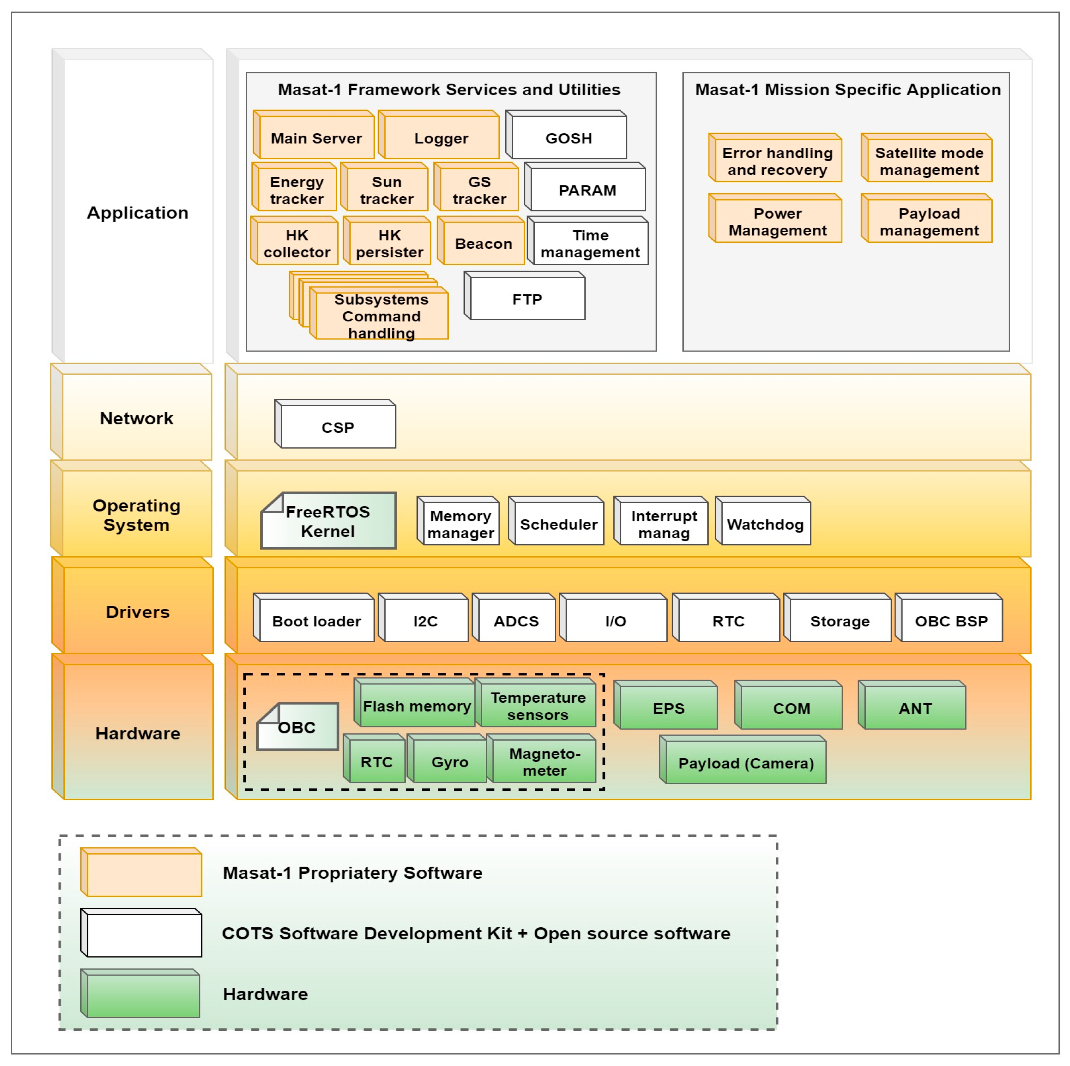
7. Masat-1 Flight Software Architecture Design and Implementation
7.1. Drivers Layer
7.2. Operating System Layer
7.3. Network Layer
7.4. Application Layer
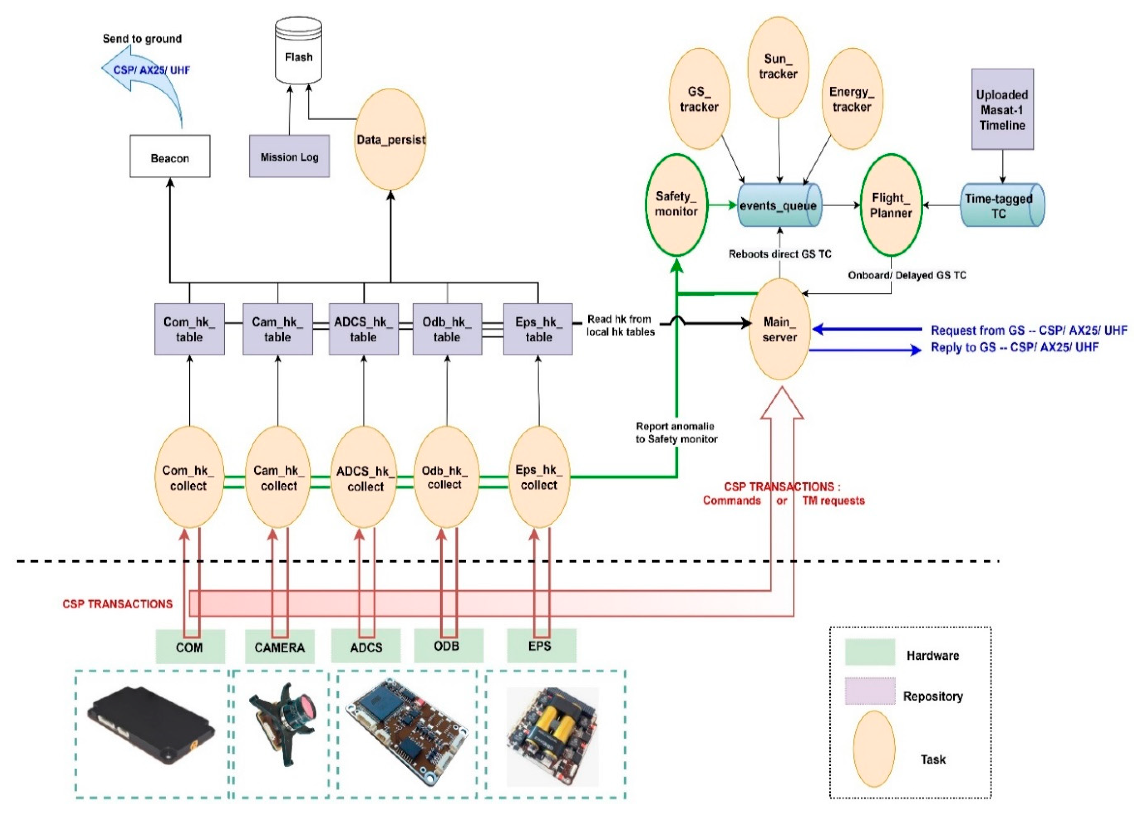
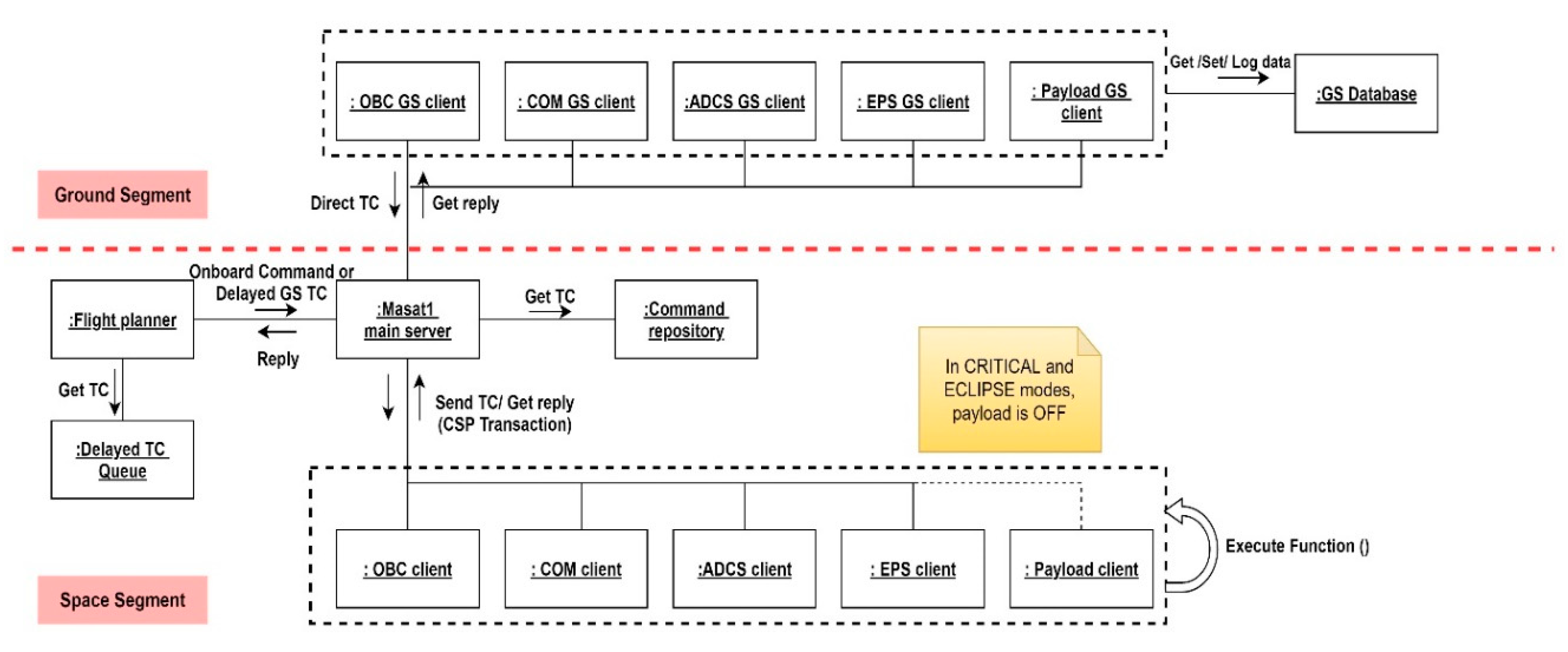
- Architectural choices: Masat-1 flight software architecture pattern contributed to Masat-1 overall reliability by increasing system robustness through the loose coupling of modules and services. Additionally, a finite state machine was implemented at the level of the flight planner to manage Masat-1 operations in a deterministic manner. It also offered a simple and clean implementation of the control logic of the spacecraft.
- Defensive programming: our solution was implemented in the C language using a defensive programming approach to develop a deterministic flight software with predictable behavior despite the unexpected user/event inputs. This also enhanced software bug detectability and isolation.
- Event logging includes errors/failures reporting and the logging of important operations, such as packet events, queues or housekeeping data-persisting files creation/deletion after a reboot, etc. Distinct text files were used to differentiate between these events. Readable text files were used instead of binary files to facilitate the tracking of onboard operations and errors/failures in a timely manner. Besides, error logging was very helpful during software debugging and testing.
- Fault-tolerance
- Hierarchical FDIR architecture: several levels of faults are defined from units up to the mission/system level (Table 6). The “flight planner” that is the highest FDIR level is in charge of the execution of vital functions/ground commands to ensure the spacecraft integrity and safety; while lower level hierarchies, namely the “safety monitor” and the “housekeeping collectors” are responsible for errors/faults detection in the subsystem and component levels. Therefore, the Masat-1 FDIR hierarchical system is at the same time centralized and distributed: centralized as the on-board fault tolerance decisions are made at a single location, at the level of the flight planner. It is distributed in a sense that each subsystem implements part of the overall FDIR architecture by mapping FDIR functions versus the hardware and/or software safety functions. This concept allows the reuse of the centralized part and the decoupling of the FDIR levels; thus, enhancing system fault management modularity.To monitor the system health and detect anomalies, several detection methods depending on the type of errors/failures were implemented. Here, we present some of them: units’ internal health checks are easy to perform thanks to the units’ housekeeping data and events raised by built-in safety functions. These provided the health status reporting, and they will be sent to the ground for further analysis. They will also be used on-board to raise a local alarm. This detection method is applied mostly to monitor on-board sensors and actuators. Data transmission checks aim at detecting protocol communication anomalies. For example, received commands’ node and ID numbers are checked against “Masat-1 services repository”. If no match is found, the command is dropped, and the error is reported in the error events log. This concerns all the items connected to the CSP network. Consistency checks concern the data values monitoring. Two techniques were considered: the first one was rule-based limit checks to monitor the measures provided by a sensor or an actuator. For instance, if the values provided by temperature sensors of the EPS are consistently lower than a certain threshold, the heating system will be activated automatically. The second one is command consistency; onboard routines were implemented to verify the right execution of a given command. In a default case, a number of command retries is issued. After the failure of all attempts, the error is reported in the log, and an alarm is raised to higher FDIR levels. Therefore, quick detection time and efficient decision making are key factors during a failure scenario. Furthermore, important sensor data, such as voltages, currents, temperatures and orbit and attitude parameters are collected periodically and sent to the ground to be checked for safe operations. Other detection techniques include the periodic checks of flags for running tasks and periodic pinging to subsystems. For example, the OBC is a single point failure in Masat-1-centralized architecture. To mitigate this weak point, we used external watchdogs in the EPS to monitor the OBC’s well functioning. Periodic pings are sent; in case of any anomaly, after five failing pings, the EPS will reset the OBC, and the COM will send its own telemetry only to GS in a periodic beacon during the communication window. We used the same strategy to detect communication failures with the ground; if no packet is received within a predefined period from the ground, a local “RX idle timer” is set to reinitialize the receiver configuration. If the failure persists, an external watchdog in the EPS will induce the complete system reset. Periodic pinging and periodic checks of flags are especially useful to detect software errors/faults induced by single events upsets. They both rely on watchdog timers to monitor SW/HW items well functioning.Upon the detection of anomalies, events are raised and are handled through a decision matrix (event/action correlation) implemented at the level of the “safety monitor”. For failures at the subsystem or system level, the safety monitor sends signals to the flight planner to switch to safe mode. This mode was implemented to maintain the spacecraft in a safe-guarding configuration when major anomalies occur, and it will remain in this state until next contact with the ground segment. Indeed, a fail-safe approach was selected instead of the safe-to-fail approach to design the Masat-1 FDIR system due to lack of hardware. During safe mode, all non-vital onboard units and subsystems are powered off to conserve power. The spacecraft shall also be pointing to nadir—ideally, while maintaining an attitude that is thermally safe and energetically optimal.
- Parameter defaulting: before launch, all Masat-1 parameters and settings are stored in “a boot-file” and “a default-file”. Both configurations are maintained in a local non-volatile memory of each subsystem for more resilience against SEU events. Unlike the boot-file, the default-file cannot be modified on orbit. This is to provision a valid backup configuration; upon first the startup or reboots, the system configuration of each module is read from the boot-file, and it can be easily modified by command. If, for some reason, the system parameters are out of range or in case of anomalies, the satellite is restored back to a valid state thanks to the backup configuration.
- Protected variables: some variables are critical for the operation of the satellite. An example of these parameters is the encryption key, which is used for the authentication of communication with the ground, or the antenna deployment status. In fact, any run time modification of these parameters due to SEU events such as bit flips might jeopardize the mission. Therefore, the identification and persisting of these parameters is crucial.
- System Reconfigurability: the Masat-1 parameter system enables the easy reconfiguration and calibration of the system without lengthy software upload. Besides, all commands accept a wide range of inputs, thus enhancing the commanding system flexibility. In addition, the parameters ruling Masat-1 operations can be easily changed to fit in-orbit behavior. For instance, beacon periods can be adjusted depending on the power available on-board; the collection and persisting rates can be modified; moreover, the parameter system enables operators to change the radio basic settings to optimize its operation for better link reliability and performance.
- Throughout software validation and verification (V&V) testing: this is based on white box and integration testing. White box unitary testing will be applied to each command, since they are called independently as APIs or services provided to the ground segment. Integration tests are mini-applications running operation scenarios, such as switching the spacecraft through various states by generating events, running a command with different parameters, simulating failures scenarios, etc. This is to verify that the flight software is running in a deterministic manner and finishing tasks within specified deadlines. If an abnormal output or behavior in the software is identified, it will be fixed, and tests are repeated again. When integrated in its end environment, the overall reliability of the flight-control software is assessed using functional validation testing all within SIL and HIL simulations on a virtual model of each subsystem. Hardware–software interaction analysis (HSIA) will be used to analyze flight software reactions to hardware failures. It is worth mentioning that we also intend to use this V&V testing campaign to identify all failure modes that were unaccounted for during FMECA analysis. In such cases, the FMECA will be updated, the effects of new failure modes induced by these modifications will be evaluated, and adequate preventive/corrective functions will be implemented.
8. Conclusions
- A modular hardware architecture based on COTS modules with extensive flight heritage in conjunction with rigorous functional and system integration testing; modularity shall increase the system reliability because it enhances errors/failures isolation.
- Defensive programming to develop a deterministic flight software with predictable behavior despite unexpected user/event inputs. This will also enhance software bugs detectability and isolation.
- A modularflight software architecture: a layered service-oriented pattern coupled with CSP network infrastructure was used to ensure a modular and loosely coupled architecture. Furthermore, the control logic of the spacecraft is based on a finite state machine implemented at the application layer. When coupled with a closed mode CONOPS, this will ensure the deterministic behavior of the spacecraft.
- Fault management techniques such as a hierarchical FDIR architecture. FDIR functions were implemented at the system and subsystem levels to lead the spacecraft to its safe mode after a software failure or/and minor hardware faults, while waiting for ground intervention.
- Throughout software V&V using white box unitary and integration testing. When integrated in its end environment, the overall reliability of the flight-control software is assessed using functional validation testing all within SIL and HIL simulations. Hardware Software Interaction Analysis (HSIA) might be used to analyze flight software reactions to hardware failures. This way, the V&V testing campaign will also help compensating for drawbacks of functional FMECA and possible inaccuracies of RBD results. Indeed, exhaustive testing will help identifying all unforeseen failure modes that might emerge during Masat-1 operational phase in-orbit. In such cases, the FMECA will be updated, effects of new failure modes induced by these modifications will be evaluated, and adequate preventive/corrective functions will be implemented. This process will continue even after satellite launch. This way, statistical data about the nature of any potential failures detected in orbit and their causes are accumulated, and the lessons learned built upon them will contribute to further enhancement of subsequent missions’ overall reliability.
Author Contributions
Funding
Conflicts of Interest
References
- Latachi, I.; Rachidi, T.; Karim, M.; Hanafi, A. Building Low Cost CubeSat: Guidelines and Design Approach; Univelt, Inc.: Escondido, CA, USA, 2018; Volume 163. [Google Scholar]
- Hanafi, A. Etude et Conception du Segment Spatial du Nanosatellite Universitaire Masat-1 Avec Ordinateur de Bord Secondaire Reconfigurable à Base de FPGA. Ph.D. Thesis, Université Sidi Mohammed Ben Abdellah, Fez, Morocco, October 2017. [Google Scholar]
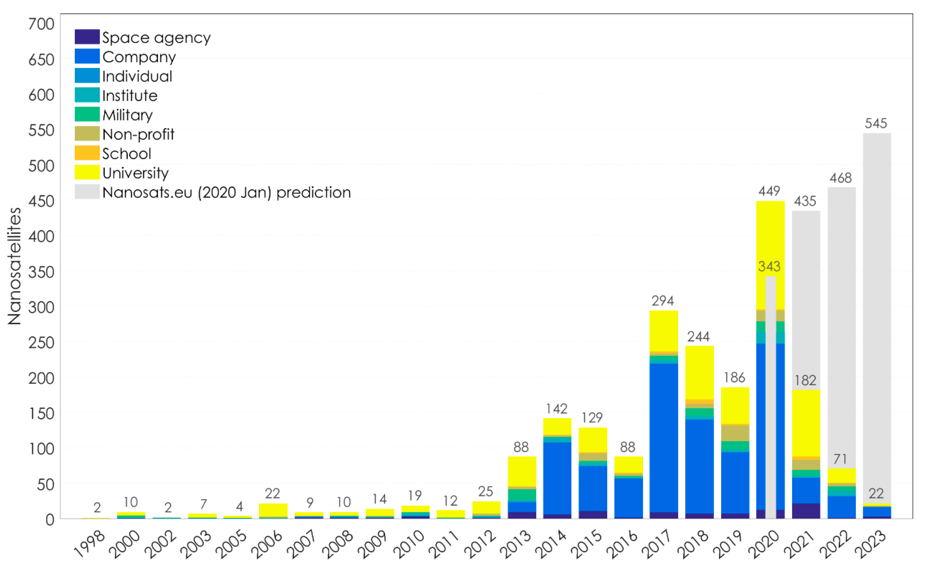
- Available online: https://www.nanosats.eu/ (accessed on 21 January 2020).
- Eickhoff, J. Onboard Computer, Onboard Software and Satelllite Operations; Springer: Berlin/Heidelberg, Germany, 2012. [Google Scholar]
- Nieto-Peroy, C.; Emami, M.R. CubeSat Mission: From Design to Operation. Appl. Sci. 2019, 9, 3110. [Google Scholar] [CrossRef] [Green Version]
- Langer, M. Reliability Assessment and Reliability Prediction of CubeSats through System Level Testing and Reliability Growth Modelling. Ph.D. Thesis, Technische Universität München, Munich, Germany, 2018. [Google Scholar]
- ESA-ESTEC, ECSS-Q-ST-30-02-C. In Space Product Assurance—Failure Modes, Effects and Criticality Analysis (FMEA/FMECA); ESA-ESTEC: Noordwijk, The Netherlands, 2009.
- Gelmi, S. Fault Detection Isolation and Recovery for LUMIO mission: Algorithm and methodology. Master’s Thesis, Delft University of Technology, Delft, The Netherlands, 2019. [Google Scholar]
- ESA. Effective Reliability Prediction for Space Applications. 2016. Available online: https://www.reliability.space/app/download/14847209524/ESA_WhitePaper_2016.pdf?t=1518002321. (accessed on 30 September 2020).
- PC/104 Embedded Consortium, “PC/104 Specification—Version 2.6,” 13 October 2008. Available online: https://pc104.org/wp-content/uploads/2015/02/PC104_Spec_v2_6.pdf (accessed on 13 September 2020).
- ECSS-E-ST-70-11C. In Space Engineering—Space Segment Operability; ESA-ESTEC: Noordwijk, The Netherlands, 2008.
- Gessner, R.; Kösters, B.; Hefler, A.; Eilenberger, R.; Hartmann, J.; Schmidt, M. Hierarchical FDIR Concepts in S/C Systems. In Proceedings of the Space OPS 2004 Conference; American Institute of Aeronautics and Astronautics (AIAA), San Diego, CA, USA, 28−30 September 2004. [Google Scholar]
- Wander, A.; Förstner, R. Innovative fault detection, isolation and recovery on-board spacecraft: Study and implementation using cognitive automation. In Proceedings of the 2013 Conference on Control and Fault-Tolerant Systems (SysTol), Nice, France, 9−11 October 2013; pp. 336–341. [Google Scholar]
- Xavier, O. FDI(R) for satellites: How to deal with high availability and robustness in the space domain? Int. J. Appl. Math. Comput. Sci. 2012, 22, 99–107. [Google Scholar]
- Shummer, F. Reliability Assessment of Small Spacecraft Before Launch. 2017. Available online: https://www.researchgate.net/publication/334132239_Reliability_Assessment_of_Small_Spacecraft_Before_Launch (accessed on 11 September 2020).
- Birolini, A. Reliability Engineering; Springer Science and Business Media LLC: Berlin, Germany, 2010. [Google Scholar]
- NASA. Fault Tree Handbook with Aerospace Applications. 2002. Available online: http://www.mwftr.com/CS2/Fault%20Tree%20Handbook_NASA.pdf. (accessed on 14 September 2020).
- Shafiee, M.; Enjema, E.; Kolios, A. An Integrated FTA-FMEA Model for Risk Analysis of Engineering Systems: A Case Study of Subsea Blowout Preventers. Appl. Sci. 2019, 9, 1192. [Google Scholar] [CrossRef] [Green Version]
- Rausand, M.; Barros, A.; Hoyland, A. System Reliability Theory—Models, Statistical Methods, and Applications, 2nd ed.; John Wiley & Sons: Hoboken, NJ, USA, 2020. [Google Scholar]
- Department of Defense, USA, Mil-Std-1629a-Military Standard—Procedures for Performing, a Failure Mode, Effects and Crltlcalliv Analysis. 24 November 1980. Available online: https://www.fmea-fmeca.com/milstd1629.pdf. (accessed on 13 September 2020).
- Stesina, F.; Corpino, S. Investigation of a CubeSat in Orbit Anomaly through Verification on Ground. Aerospace 2020, 7, 38. [Google Scholar] [CrossRef] [Green Version]
- Shiotani, B. Reliability Analysis of Swampsat. 2011. Available online: https://ufdc.ufl.edu/UFE0043397/00001 (accessed on 17 January 2020).
- Menchinelli, A.; Ingiosi, F.; Pamphili, L.; Marzioli, P.; Patriarca, R.; Costantino, F.; Piergentili, F. A Reliability Engineering Approach for Managing Risks in CubeSats. Aerospace 2018, 5, 121. [Google Scholar] [CrossRef] [Green Version]
- Li, J. Reliability Comparative Evaluation of Active Redundancy vs. Standby Redundancy. Int. J. Math. Eng. Manag. Sci. 2016, 1, 122–129. [Google Scholar] [CrossRef]
- Jacklin, S.A. Small-Satellite Mission Failure Rates; Nasa Ames Research Center: Mountain View, CA, USA, 2019. [Google Scholar]
- Tafazoli, M. A study of on-orbit spacecraft failures. Acta Astronaut. 2009, 64, 195–205. [Google Scholar] [CrossRef]
- Asundi, S.A.; Fitz-Coy, N.G. Design of command, data and telemetry handling system for a distributed computing architecture CubeSat. In Proceedings of the 2013 IEEE Aerospace Conference, Big Sky, MT, USA, 2–9 March 2013; pp. 1–14. [Google Scholar]
- Latachi, I.; Karim, M.; Hanafi, A.; Rachidi, T.; Khalayoun, A.; Assem, N.; Dahbi, S.; Zouggar, S. Link budget analysis for a LEO cubesat communication subsystem. In Proceedings of the 2017 International Conference on Advanced Technologies for Signal and Image Processing (ATSIP), Fez, Morocco, 22–24 May 2017; pp. 1–6. [Google Scholar]




| (a) Mission Operations Autonomy Levels According to ECSS-E-ST-70-11C | ||
| Level | Description | Functions |
| E1 | Mission execution under ground control; limited on-board capability for safety issues | • Real-time control from ground for nominal operations • Execution of time-tagged commands for safety issues |
| E2 | Execution of pre-planned, ground-defined, mission operations on-board | • Capability to store time-based commands in an on-board scheduler. |
| E3 | Execution of adaptive mission operations on-board | • Event-based autonomous operations • Execution of on-board operations control procedures |
| E4 | Execution of goal-oriented mission operations on-board | • Goal-oriented mission re-planning. |
| (b) Failure and Fault Management Autonomy Levels According to ECSS-E-ST-70-11C | ||
| Level | Description | Functions |
| F1 | Establish safe space segment configuration following an on-board failure | • Identify anomalies and report to ground segment • Reconfigure on-board systems to isolate failed equipment or functions • Place space segment in a safe state |
| F2 | Re-establish nominal mission operations following an on-board failure | • As F1, plus reconfigure to a nominal operational configuration • Resume execution of nominal operations • Resume generation of mission products |
| (a) | ||
| Severity Category | Severity Number (SN) | Impact |
| Catastrophic | 4 | Total mission failure. |
| Critical | 3 | Partial loss of subsystems’ services, and recovery is not possible. Mission is partially compromised. |
| Major | 2 | One or many subsystems/processes are affected by the unit fault/failure, but recovery is possible. Minor/major degradation in mission performance. |
| Minor | 1 | No vital subsystem/process is affected by the unit fault/failure. |
| (b) | ||
| Likelihood of Occurrence | Probability Level (PN) | |
| Probable: Custom SW/HW components with no space heritage, or failure mode probability is high as it occurred in almost every similar mission. | 4 | |
| Occasional: Custom SW/HW components and COTS with little space heritage, or failure mode probability is moderate as it occurred many times in similar missions. | 3 | |
| Remote: COTS with little space heritage, or failure mode probability is low as it occurred once or twice in similar missions. | 2 | |
| Extremely Remote: COTS with considerable space heritage, or failure mode probability is extremely low as it has never been experienced in similar missions. | 1 | |
| Severity Category | SNs | Probability Level | |||
|---|---|---|---|---|---|
| 10−5 | 10−3 | 10−1 | 1 | ||
| PNs | |||||
| 1 | 2 | 3 | 4 | ||
| Catastrophic | 4 | 4 | 8 | 12 | 16 |
| Critical | 3 | 3 | 6 | 9 | 12 |
| Major | 2 | 2 | 4 | 6 | 8 |
| Minor | 1 | 1 | 2 | 3 | 4 |
| Subsystem | Non-Redundancy | Redundancy | Reliability Growth through Redundancy % |
|---|---|---|---|
| ADCS | 0.5904 | 0.6495 | 6.56% |
| EPS | 0.5904 | 0.6495 | 6.56% |
| COM | 0.729 | * Partial: 0.8019 ** Full: 0.9265 | Partial: 8.1% Full: 21.9% |
| OBC | 0.656 | Partial: 0.7217 Full: 0.8817 | Partial: 7.3% Full: 25% |
| ANT | 0.8675 | N/A | N/A |
| Failure Mode | Potential Impact on: a. Local b. Other Subsystems c. Mission/Satellite | Error/Failure Causes | Severity (SN) | Probability (PN) | Criticality (CN) |
|---|---|---|---|---|---|
| Levels 2 and 3: Mission/Satellite | |||||
| EPS System Failure | a. No power supplied b. Loss of all subsystems c. Mission failure | • EPS board components failure • Photovoltaic panels failure • Batteries failure • Connections failure • RBF pin failure • Deployment switch malfunction | 4 4 4 4 3 4 | 1 2 2 2 3 3 | 4 8 8 8 9 1 2 |
| EPS Low Power | a. Less power available onboard b. Only vital systems are ON c. Mission partially compromised; mission lifetime reduction | • Batteries not fully charged ○ Charging voltage level below threshold Vsafe. ○ False battery DoD readings • Boost converters not provided with enough power • Battery over discharge due to other subsystems design errors • ADCS failure | 1 3 3 3 3 | 4 2 1 2 2 | 4 6 3 6 6 |
| EPS Communication with OBC Failure | a. Unable to provide power information to OBC b. Wrong satellite mode switching c. Mission performance degradation | • I2C communication error/failure • EPS control software error/failure • EPS system failure • OBC board failure • Flight software error/failure | 3 3 4 4 3 | 2 2 2 2 3 | 6 6 8 8 9 |
| Failure Mode | Potential Impact on: a. Local b. Other Subsystems c. Mission/Satellite | Error/Failure Causes | Severity (SN) | Probability (PN) | Criticality (CN) |
|---|---|---|---|---|---|
| Level 1: Subsystems | |||||
| Batteries Failure | a. Fail to store power b. No power provided to subsystems c. Mission failure | • Outgassing • Explosion • Battery wirings disconnected | 4 4 4 | 2 1 2 | 8 4 8 |
| Batteries Overheating | a. Life cycle reduced b. Decrease in power budget c. Decrease in mission lifetime | • Short circuit | 2 | 2 | 4 |
| Batteries Underheating | • Heating system faults | 2 | 2 | 4 | |
| Photovoltaic Panels Failure | a. Fail to produce power b. Low/no power provided to subsystems c. Mission partially/totally compromised | • Excessive mechanical loads during launch • Environmental radiations | 4 3 | 3 4 | 12 12 |
| EPS Control Software Failure | a. Inaccurate power budget estimation b. Low/no power provided to subsystems c. Mission partially/totally compromised | • Environmental radiations • Operation failure due to wrong GS commands • Software bugs • Electrical failure | 3 3 3 4 | 4 2 1 2 | 12 6 3 8 |
| EPS Board Failures | a. Fail to distribute power b. Low/no power provided to subsystems c. Mission partially/totally compromised | • Burnout due to radiations, overcurrent or out of range temperature. • Physical damage due to high mechanical load during launch | 4 4 | 2 2 | 8 8 |
| Impact of Failure per Level | Fault Detection Techniques per Level | Fault Recovery Techniques per Level | |
|---|---|---|---|
| Level 0: Units | Unit faults: short currents, overvoltage, over temperature, etc. No impact on subsystem performance. | Local in unit: safety measures and watchdogs; log failures to inform ground. | SW/HW built-in safety functions; local correction. |
| Level 1: Subsystems | Minor failures: errors/faults of units or communication interfaces. Degraded subsystem performance. | In respective subsystem level: limit checking; diagnosis of housekeeping data, critical parameters control | Command retry, log failures to inform ground, and isolate problem; switch to safe mode. |
| Level 2 and 3: Satellite and Mission | Major SW/HW subsystem failures: one or more subsystems are affected; partial/total loss of vital subsystems’ services. Anomalies of the OBC module or SW. Mission is partially compromised in terms of performance or limited operations. | Several alarms from level 0 and 1, faults on FDIR units, hardware alarms or control software alarms. | Switch to safe mode; subsystems reboots.Subsystem reconfiguration. |
© 2020 by the authors. Licensee MDPI, Basel, Switzerland. This article is an open access article distributed under the terms and conditions of the Creative Commons Attribution (CC BY) license (http://creativecommons.org/licenses/by/4.0/).
Share and Cite
Latachi, I.; Rachidi, T.; Karim, M.; Hanafi, A. Reusable and Reliable Flight-Control Software for a Fail-Safe and Cost-Efficient Cubesat Mission: Design and Implementation. Aerospace 2020, 7, 146. https://doi.org/10.3390/aerospace7100146
Latachi I, Rachidi T, Karim M, Hanafi A. Reusable and Reliable Flight-Control Software for a Fail-Safe and Cost-Efficient Cubesat Mission: Design and Implementation. Aerospace. 2020; 7(10):146. https://doi.org/10.3390/aerospace7100146
Chicago/Turabian StyleLatachi, Ibtissam, Tajjeeddine Rachidi, Mohammed Karim, and Ahmed Hanafi. 2020. "Reusable and Reliable Flight-Control Software for a Fail-Safe and Cost-Efficient Cubesat Mission: Design and Implementation" Aerospace 7, no. 10: 146. https://doi.org/10.3390/aerospace7100146
APA StyleLatachi, I., Rachidi, T., Karim, M., & Hanafi, A. (2020). Reusable and Reliable Flight-Control Software for a Fail-Safe and Cost-Efficient Cubesat Mission: Design and Implementation. Aerospace, 7(10), 146. https://doi.org/10.3390/aerospace7100146


