Article

Heavy Ion Induced Single Event Effects Characterization on an RF-Agile Transceiver for Flexible Multi-Band Radio Systems in NewSpace Avionics

1
Institute of Space Systems, German Aerospace Center (DLR), Robert-Hooke-Str. 7, 28359 Bremen, Germany
2
European Organization for Nuclear Research (CERN), CH1211 Geneve, Switzerland
3
Electronics and Sensor Systems, Brandenburg University of Technology Cottbus-Senftenberg (BTU), Siemens-Halske-Ring 14, 03046 Cottbus, Germany
*
Author to whom correspondence should be addressed.
Aerospace 2020, 7(2), 14; https://doi.org/10.3390/aerospace7020014
Submission received: 13 January 2020 / Revised: 5 February 2020 / Accepted: 7 February 2020 / Published: 9 February 2020
(This article belongs to the Special Issue Single Event Effect Prediction in Avionics)

Abstract

:
Nowadays, technologies have a massive impact on the design of avionic systems, even for the conservative space industry. In this paper, the single event effect (SEE) characterization of a highly integrated and radio frequency (RF) agile transceiver is being presented which is an outstanding candidate for future radio systems in NewSpace applications and space avionics. The device being investigated allows programmable re-configuration of RF specifications, where classical software-defined radios (SDR) only define an on-demand re-configuration of the signal processing. RF related configurations are untouched for common SDR and developed discretely by the specific application requirements. Due to the high integrity and complexity of the device under test (DUT), state-of-the-art radiation test procedures are not applicable and customized testing procedures need to be developed. The DUT shows a very robust response to linear energy transfer (LET) values up to 62.5 MeV.cm²/mg, without any destructives events and a moderate soft error rate.

1. Introduction

The Institute of Space System of the German Aerospace Center (DLR) is recently developing a highly integrated multi-band software-defined radio (SDR) platform for space applications with a radiation-tolerant approach [1,2]. State-of-the-art SDR systems in space avionics are typically limited to the re-configuration of the signal processing algorithms in the digital domain. Radio frequency (RF) relevant parameters, such as the RF bandwidth, mixing frequency, or the sample rate for analog to digital conversion (and vice versa) are specified by the operated application of these SDRs. New radio frequency integrated circuit (RFIC) technology designed for terrestrial applications (e.g., mobile services—5G) allows a software-based re-configuration of RF front-end related properties, but investigations about their behavior in a radiation environment are required for their utilization in space avionics. In previous works, the selected RFIC device has already been tested for total ionizing dose (TID) effects [2,3] and a characterization of proton-induced single event effects (SEE) has been performed [4]. In this paper, the heavy ion-induced SEE characterization of this RFIC device is presented. In Section 2, the device under test (DUT), the highly integrated and RF agile transceiver is presented. The test conditions and requirements are presented in Section 3 and the test procedures and test setup are given in Section 4. The test results of this SEE characterization under heavy ion are described in Section 5 and are later discussed in Section 6. The conclusion is made in Section 7.

2. The Highly Integrated Radio Frequency (RF)-Agile Transceiver

The selected RFIC is the AD9361, a RF-agile transceiver from Analog Devices that has been evaluated as an excellent candidate for future space avionic radio systems. The AD9361 device is a 2 × 2 RF transmitter and receiver including up to six individual RF front-ends, a mixed-signal baseband (BB) unit with an integrated frequency synthesizer, using a selectable low voltage differential signaling (LVDS) high speed digital interface. All functionalities of this device can be re-configured by software over a serial peripheral interface (SPI). A functional block diagram of the AD9361 is presented in Figure 1.
The different functions of the DUT are described in more detail in the following sections. Further information about the specification and performance of the selected DUT can be taken from the data sheet in [6].

2.1. Device Packaging and Chip Technology

The AD9361 is encapsulated in a 10 × 10 × 1.7 mm³, 144-pin chip scale package ball grid array housing. The semiconductor die is based on a 65 nm complementary metal-oxide-semiconductor (CMOS) process. A side-view X-ray picture of the device in Figure 2 shows that the die is located faced-up on a printed circuit board (PCB) stack interfaced with bond-wires.
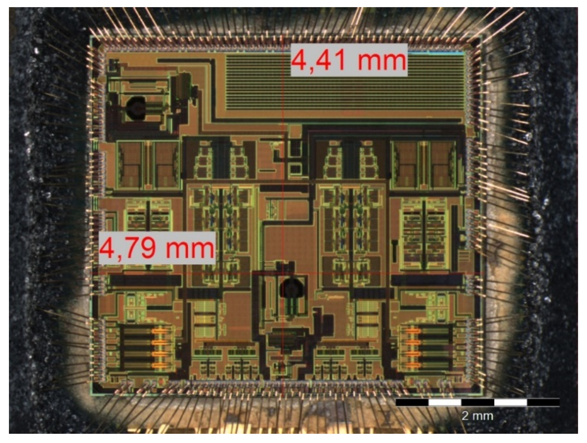
The molding compound is based on silica (86.20%), epoxy resin (6.00%), phenol resin (6.00%), metal hydroxide (1.50%), and carbon black (0.30%) [7]. Due to the plastic encapsulation, the devices need to be opened to test under heavy ion irradiation. Figure 3 shows the etched DUT with the exposed die surface and its measured dimensions. The die itself has a size of approximately 4410 × 4800 µm². The die has several metallization layers above the active regions (sensitive volume) which can be illustrated in a cross section view with a focused ion beam (FIB).
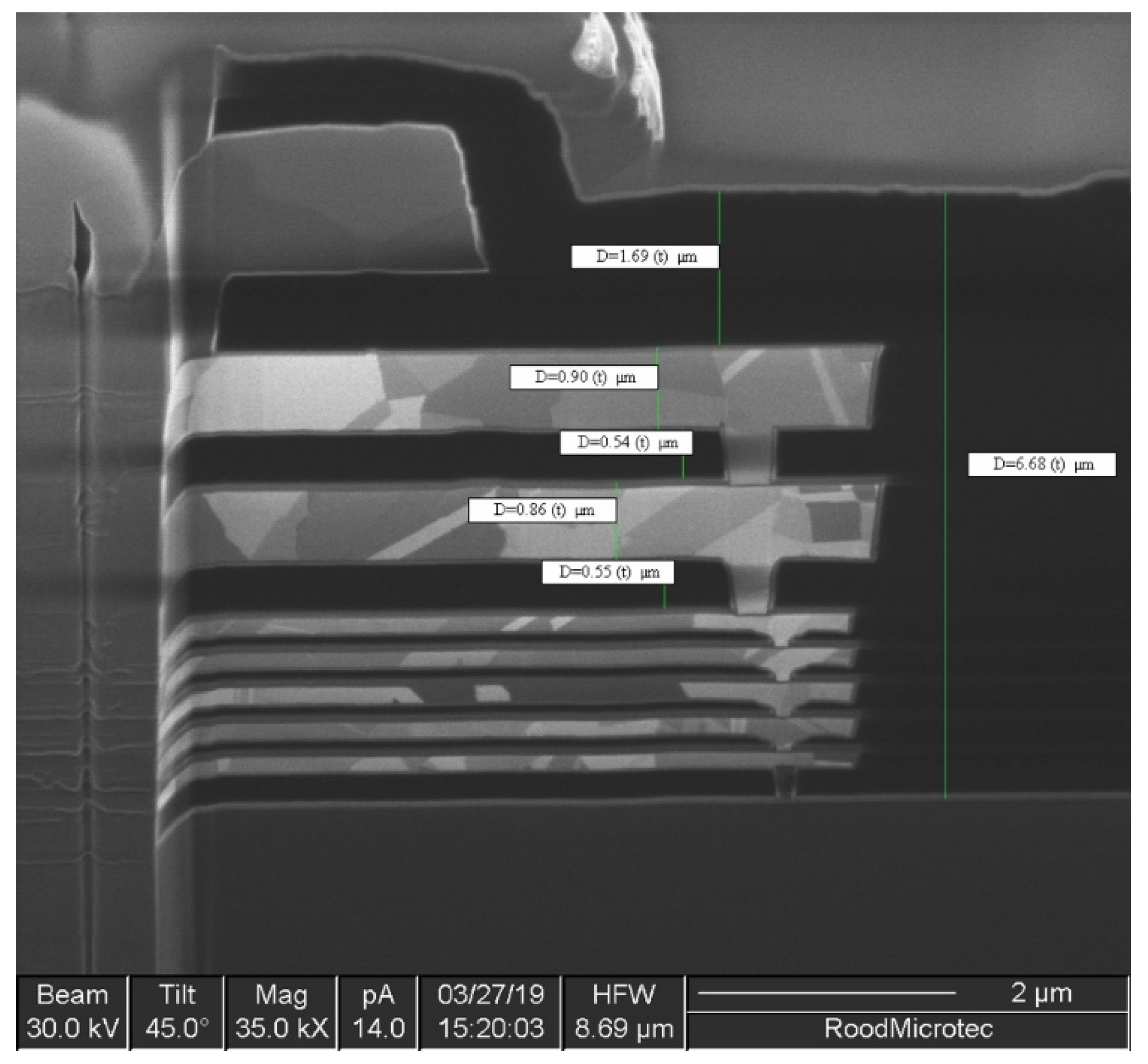
The FIB cross section in Figure 4 shows that a 7-metal-layer is used by the manufacturer. The layers are made of copper and have a thickness from approximately 300 to 900 nm. The dielectric material separating the metallization layers is silicon dioxide and has a thickness ranging from 550 nm to 6.68 µm.
The total thickness of those materials depends on the number of layers being used which varies by the local position of the die. The layer thickness and its material information become important to estimate the effective linear energy transfer (LET) on the active region when exposing the DUT with the heavy ions. The influence of the metallization layers to the LET in the active region will be discussed in more detail in Section 6.6.

2.2. Test Setup Preparation and Sample Information

For the heavy ion irradiation test, a specific test board has been developed to support accurate data processing of the DUT. The test board presented in Figure 5 consists of a Xilinx field programmable gate array (FPGA), a set of non-volatile and volatile memories, digital interfaces, power regulation devices, and the AD9361 (red frame). The data is processed by the FPGA in combination with two double data rate synchronous dynamic random access memory and is then streamed via Ethernet to the external test setup. Dedicated test points are provided to monitor the voltage and current behavior of the DUT.
The test board has been designed and tested for continuous operation under vacuum since the chosen test facility does not support heavy ion irradiation in air, mainly due to the limited heavy ion energy and range. To retrieve more accurate statistics, two boards have been manufactured to irradiate two samples individually. Table 1 shows the board and DUT sample information.
The device is being manufactured only on a single fabrication site and Analog Devices provides a product notification service that informs about changes in the process. Based on the lot date code and the product notification service of analog devices, it can be ensured that both samples are from of the same lot and similar test results can be expected.

3. Test Conditions and Requirements

3.1. Test Site

The selected test site for the heavy ion irradiation test campaign is the heavy ion facility (HIF) of the Cyclotron Resource Centre of the Catholic University of Louvain (UCL). The ion beams are produced with the UCL cyclotron Cyclone-110. A coupling of the cyclotron with an electron cyclotron resonance ion source working at 17.3 GHz produces a heavy ion cocktail with ~9.3 MeV/nucleon (M/Q = 3.33). The 25 mm diameter beam is provided with homogeneity better than 10%. In Table 2, the provided and used types of ions in the cocktail with their energy on device range in silicon and LET is presented.
The HIF is operated in vacuum and supports an XY-table that can be moved remotely. The area that could be centered in the beam is about 230 × 230 mm². The vacuum chamber supports numerous types of flanges to interface the DUT and test board.

3.2. Test Requirements

The selected test requirements are primarily referred to the European space components coordination (ESCC) test method and guidelines No. 25100 [8]. Due to the complexity of the DUT and its highly integrated functional architecture, a tailoring of the ESCC No. 25100 was considered. Both DUTs have been tested in two separated test campaigns. During the first campaign, the major objective was observing critical SEEs, such as single event latch-ups (SEL) and other destructive events. Therefore, both DUTs have been irradiated to target fluence of 1 × 10⁷ #/cm² with an LET of up to 62.5 MeV.cm²/mg. Using different incident/tilt angles increases the effective LET of up to 125 MeV.cm²/mg (Xe, tilt–pitch angle: 60°).
In a second test campaign, the target fluence and the average flux has been reduced to investigate the soft error response, such as for single event upsets (SEU) in the device functional registers and recoverable single event functional interrupts (SEFI).

4. Test Setup and Procedures

4.1. Test Setup

The setup presented in Figure 6 consists of a command and control (C&C) server running Linux and the DUTs with a corresponding secondary reference device (REF) outside the irradiated area to send and receive RF data. Both DUTs are physically interconnected via coax cables for RF transmission. The server connection to both devices is realized via Ethernet and a serial interface for debugging purposes. The test boards with the DUTs and the beam-shutter are supplied and controlled with a remote-controlled power supply unit.
A program runs on the test board to check the DUT functional registers, to detect failures in the device configuration and receive/transmit RF data. Both programs are started remotely from the C&C server, which is in control of the whole test procedure.

4.2. Failure Classification

Failures are generally categorized in potential destructive and non-destructive events. For the DUT, SELs are the most critical event that could destroy the device permanently. Non-destructive events are more likely and separated into different types.

4.2.1. Upsets in the Device Functional Registers

Upsets in the device functional registers are detected as SEUs and multiple bit upsets (MBU). The devices consist of an 8-bit register map (0x000 Hex to 0x3F6 Hex) that can be controlled via SPI. Multiple bits and registers have a relationship to each other to serve a particular function (e.g., registers used to configure automatic gain control). Thus, it is expected to observe SEFIs due to SEUs. Some registers have a continuously floating value (e.g., chip temperature) that needs to be masked for the register scrubbing process.

4.2.2. Single Event Functional Interrupts

SEFIs are separated into re-configurable functional interrupts and those where a device re-initialization is required. A re-configuration is performed by rewriting the initial functionality back to the device via SPI. In the case that a simple re-configuration fails, the device can be re-initialized by triggering a dedicated physical pin of the DUT. This re-initialization process takes a couple of microseconds and avoids a full reboot process of the test board (~25 s).

4.2.3. Corrupted Transmitted and Received RF Data

The RF data being transferred from and received by the DUT is digitized and evaluated in real-time. Expected failures in the digital in-phase/quadrature (IQ) data are glitches or single event transients (SET) that could be generated by SEEs in the integrated analog digital converter (ADC) or digital to analog converters (DAC) in the DUT. Moreover, a total corruption of the IQ data is expected, for example, due to malfunctions in the synthesizer. Transients or glitches are categorized as Soft IQ SEFI data and a total loss of the expected data is defined as Hard IQ SEFI.

4.3. Test Procedures

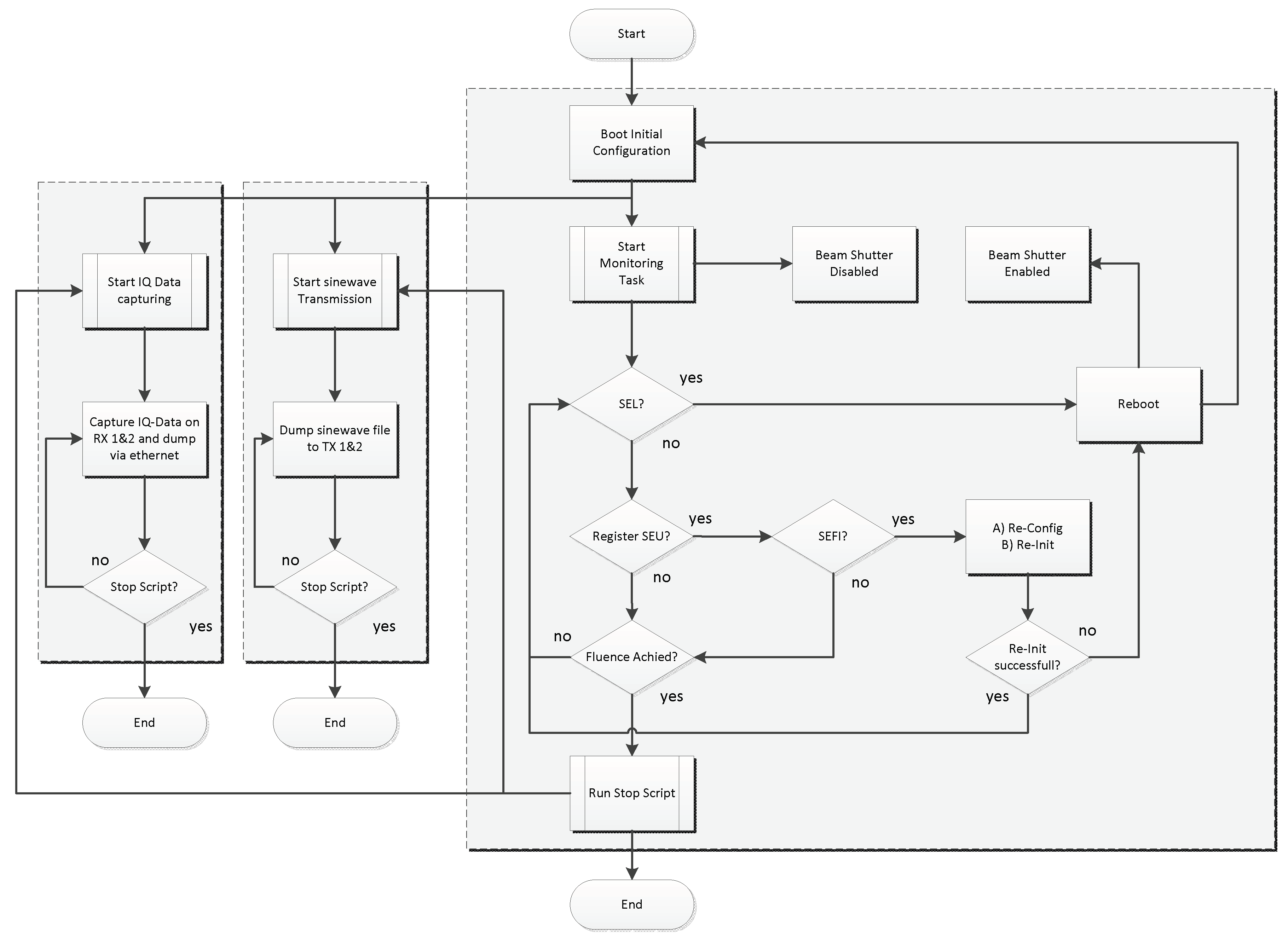
The test procedure flow chart for the AD9361 heavy ion SEE characterization is presented in Figure 7. The first step in this test procedure is the initialization of the DUT, where the correct configuration for the RF transmission is set. Secondly, the RF data is pulled from the DUT and its corresponding REF device to generate an IQ data reference data set (curve). This curve is then used during the test-run to check whether the RF data is still valid or not. If everything is set on the DUT, the test gets started with the beam-shutter opening. The supply voltages and current values are monitored with an ADC module that interrupts the test run and closes the beam shutter once an SEL or high current state is detected. The test board is then power cycled and will reboot to the nominal state.
The recent state of the functional registers and the driver values get pulled from the device every second and are compared to the initial set of data to evaluate SEUs and SEFIs. The RF data is dumped via Ethernet onto the C&C server where it is checked and compared with the generated reference curve for IQ data SEFIs.
When an error in the RF data is detected, the beam is shut off and the test is halted. The C&C control software then performs a re-initialization of the DUT and firstly verifies the correctness of the RF data before the beam shutter is being released and the run is continued. In case that the re-initialization failed three times in a row, the test board is power-cycled and one has to manually restart the test software on the test board. The RF data being transmitted is kept simple with a sinewave tone to evaluate the SEFI response as easy as possible.
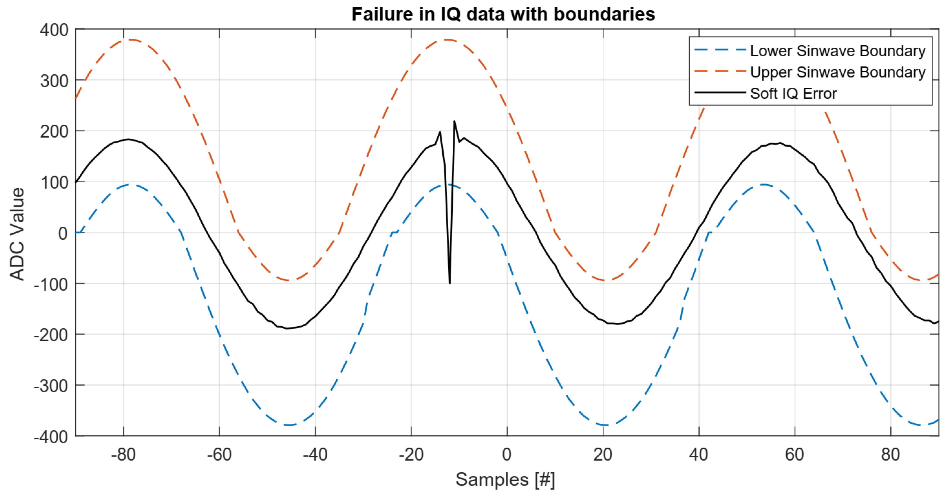
To create a reference curve from the RF data, first the periodicity and height are measured. Onto this, a margin of 10% is added to the period and 50% to the maximum of the curve. With this curve, incoming data can be compared in real time. Multiple zero crossings may be found due to the ADC quantization noise. Therefore, a margin of three bits has been applied. If the data lay not within the boundaries, a counter starts up to check if the error is continuous over at least three samples, before it is officially counted as an IQ SEFI.
A reference curve with the upper (red) and lower (blue) boundary is presented as in Figure 8. As an example for a Soft IQ SEFI, the corrupted sinewave (black) is presented as well. The evaluated sinewave glitches shortly below the lower boundary and below zero but goes back to the initial waveform without any external interaction.

5. Experimental Results

The experimental results are presented as a cross section vs. LET function for each individual classified failure. Uncertainties of the cross sections are calculated according to the recommendations given in the ESCC standard [8] with a confident level of 95%, and are highlighted with error bars in the corresponding figures. If not specified, the LETs out of Table 2 have been selected with a nominal incident angle of 0°. The influence of pitch angles is discussed separately in Section 6.5. For the cross section illustrations in Figure 9, Figure 10, Figure 11 and Figure 12, a Weibull fitting curve has been added to evaluate the LET threshold and cross section saturation. The corresponding fitting curve parameters are given in the figure captions.

5.1. Destructive Events

No destructive events have been observed during both test campaigns with a maximum LET of 62.5 MeV.cm²/mg neither at nominal incident angle, nor at an effective LET of 125 MeV.cm²/mg with a selected pitch angle of 60° on Xe. The target fluence for all runs was 1 × 10⁷ #/cm². In rare cases, high current states were observed in correlation to SEUs in the configuration registers. Those effects are discussed in Section 6.

5.2. Functional Register Upsets

SEU and MBU events have been observed for all selected LETs in a range of 3.3 to 62.5 MeV.cm²/mg. The target fluence varies between 2 × 10⁶ and 1 × 10⁷ #/cm² and depends on the SEU/MBU response and the chosen flux. The numbers of observed SEUs varies between 100 and 450 events, increasing with the LET. For MBUs, 11 to 50 events have been counted. The corresponding cross sections for SEUs (a) and MBUs (b) are presented in Figure 9. The saturation cross section is ~2 × 10⁻⁴ cm²/device for SEUs, ~1.5 × 10⁻⁵ cm²/device for MBUs, respectively. The LET threshold for both events is close to 0 MeV.cm²/mg.

5.3. Single Event Functional Interrupts

Figure 10 shows the cross sections of observed SEFIs for (a) re-configuration and (b) re-initialization failure recovery processes.
The target fluence depends on the LET and the SEFI response and varies between 3 × 10⁶ and 1 × 10⁷ #/cm². The saturation cross section SEFIs is ~1 × 10⁻⁵ cm²/device for re-configuration and ~1 × 10⁻⁶ cm²/device for re-initialization SEFIs, respectively. In general, the SEFI response that requires a re-initialization of the device was very low and has only been observed 1–3 times per run. Thus, the LET threshold differs for both DUTs (31 to 45 MeV.cm²/mg). The LET threshold for re-configuration SEFIS is close to 0 MeV.cm²/mg. Further testing to higher target fluences would have been required but was not considered during this test campaign.

5.4. Corrupted Transmitted and Received RF Data

5.4.1. Hard IQ SEFI

Hard IQ SEFIs are counted if the expected RF data is permanently lost or corrupted. Both the receiver (RX) and the transmitter (TX) chains were separately monitored and the cross sections for hard IQ SEFIs are presented in Figure 11a for RX and Figure 11b for TX.
The cross sections for both DUTs are similar and having a saturation of roughly 1 × 10⁻⁵ cm²/device. The statistical distribution for RX and TX failures is almost equal.

5.4.2. Soft IQ SEFI

Soft IQ SEFIs are counted when the expected signal deviates from the references data set but recovers to the initial waveform without any external interaction such as re-configuration or re-initialization of the DUT. Those effects can be indicated as SETs or glitches in digitized data. The cross section results are presented in Figure 12a for RX and Figure 12b for TX.
Glitches and SETs were observed much more often compared to hard IQ failures but are typically less critical and do not require a re-initialization process for the devices. Slightly more soft IQ SEFIs have been observed in the RX domain, resulting into a higher cross section compared to the soft IQ SEFIs in TX. It is assumed that the failure distribution would trend into an equal result if the numbers of failures observed would have been increased.

6. Analysis and Discussion

6.1. High Current States

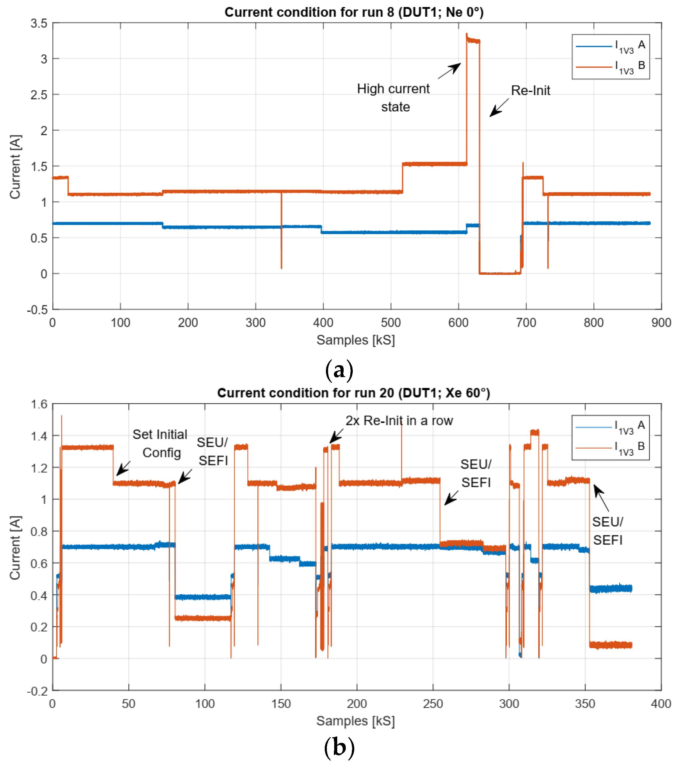
Even if no SELs or other destructive events have been observed for all tested LETs, some high current states have been monitored, which are mostly based on SEUs in the register configurations. An example of such high current states is presented in Figure 13a. As can be seen, the measured current increases from a nominal state of 1.1 Ampere on rail B to 3.2 Ampere. At the same time, several SEUs have been observed and the abnormal behavior could be reproduced in a post-test routine by changing the same registers without being affected by heavy ion irradiation.
In Figure 13b, several failures can be seen in the current consumption of the DUT. SEUs can also lead to a lower current value which could interrupt the function of the DUT (see Section 6.4). Furthermore, recovery processes by a re-initialization are shown multiple times.

6.2. SEFIs in the IQ Data

6.2.1. Soft IQ SEFIs

Soft IQ SEFIs have been observed in different ways, from simple SEUs in the ADC/DAC up to longer glitches in the IQ data.
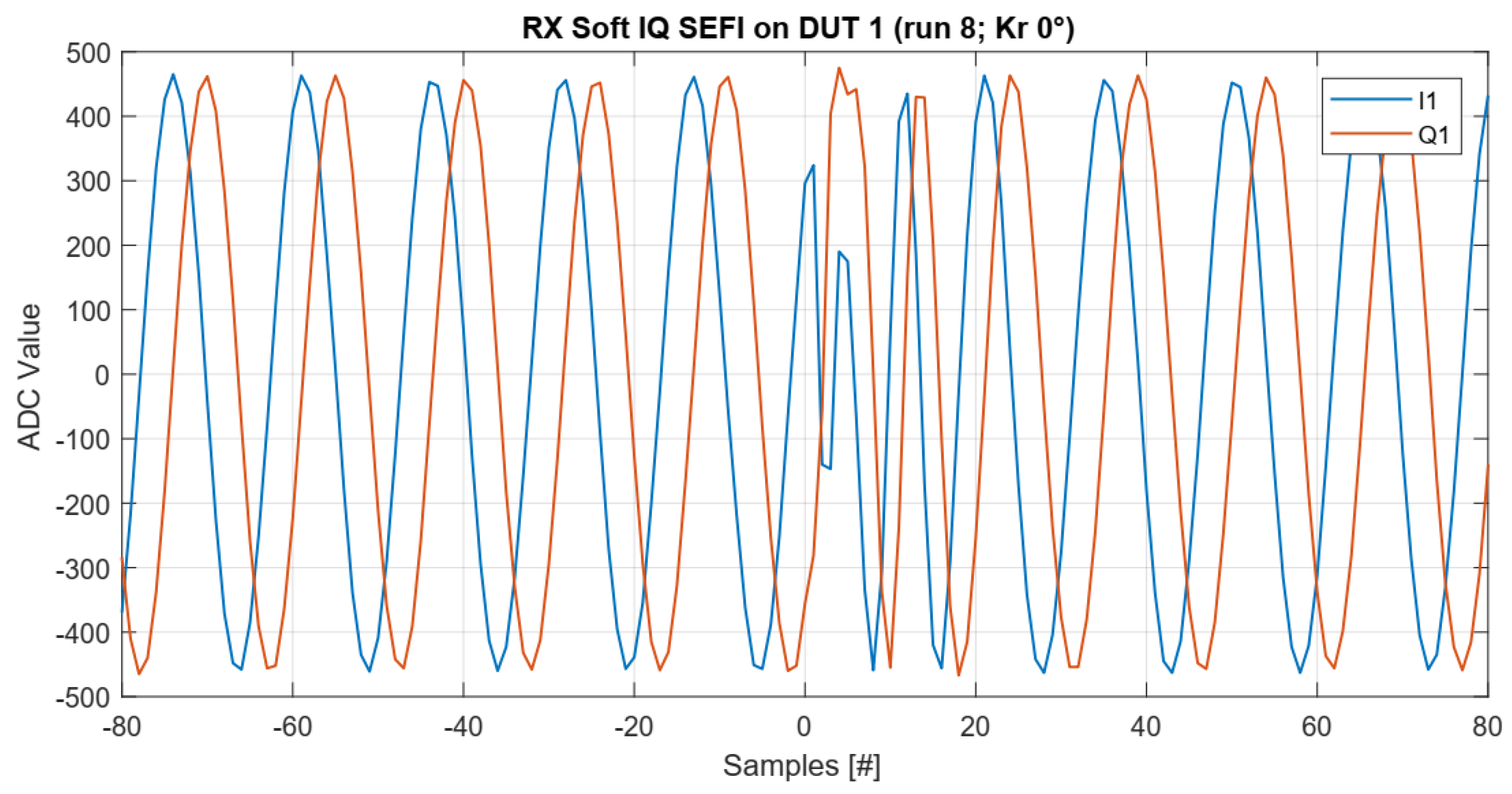
In Figure 14, an example for an SEU in the ADC data of the receiver channel 1 is presented, recorded in run 1 with Ne at 0° pitch angle. A long-termed failure of the ADC data (glitch) is presented in Figure 15. It is assumed that this malfunction is coming from the synthesizer or phase locked loop (PLL) of the DUT since the ADC values do not get stuck continuously. That type of failure would be an indicator for a failure inside of the ADC. Nevertheless, both types of failures have been observed for all runs, independently of the LET and selected pitch angle.
Soft IQ SEFIs are typically not critical since they can only increase the bit error rate (BER) for certain applications. Including error correction codes (e.g., block codes) in the specific application or data transmission can be a valid solution to mitigate the effects of soft IQ SEFIs.

6.2.2. Hard IQ SEFIs

Hard IQ SEFIs have been observed for all selected LETs. The total number of detected hard IQ SEFIs is about 50% of the recorded Soft IQ SEFIs. Two examples of observed hard IQ SEFIs are presented in Figure 16 and Figure 17.
For Figure 16, the transmitted IQ data from the DUT to the REF device has crashed and would result into a non-operating application. A re-initialization of the DUT recovers the functionality of the device and its application.
The SEFI presented in Figure 17 shows an increased value/power of the received IQ data. This type of SEFI correlates with an observed change in the driver state, where the receiver gain has been increased by about 3 dB (factor of two). The C&C control software recognized both type of events, the corrupted IQ data and the driver state change and successfully recovered these events by a re-configuration and also with a re-initialization process.

6.3. SEU and Functional Register Dependencies

Assuming a static random-access memory (SRAM)-based register structure, an equal distribution of SEUs would be expected for all registers in an infinite time. In Figure 18, the accumulated SEUs vs. functional registers are presented for different runs on DUT 1.
The accumulated SEU distribution is non-equal and particular registers showing a very high SEU response. This behavior is explained by the relationship of multiple registers and bits to each other as already noticed in the error classification section. Thus, single SEUs can cause further non-radiation related upsets. Hence, the effective numbers of upsets in the functional registers caused heavy ion-induced SEU is lower than recorded by the register scrubbing process and presented in the results. Nevertheless, the relationship is fixed by the DUT design and thus, this SEU propagation is unavoidable.
In the worst case, the SEU propagation could lead into a snow ball effect, where such high SEU values are reached as seen in Figure 19 on register 372 dez (>45 SEUs per run). In Figure 19, the accumulated SEUs for the Xe 0° run are compared to the functional register dependencies.
As can be seen, there is a match of the spikes of the dependencies and the observed and accumulated SEUs, which confirms the assumption of SEU propagations in the functional registers.

6.4. Correlation of SEUs to IQ SEFIs

It is assumed that the effect of the SEU propagation in the functional registers also affected the observed IQ SEFIs. Since the SEUs in the registers are just monitored and not restored to the initial values, except a driver state has been changed or the IQ data becomes invalid, only hard IQ SEFIs could be affected by SEUs. Table 3 shows the counted events for SEU and Hard IQ SEFIs and their ratio for all taken runs on DUT 1. Similar results are observed for DUT 2.
The average SEFI to SEU ratio is about 5%. Post-test analyses have shown that about 10% of all functional registers (and their propagation) have been responsible for Hard IQ SEFIs. Those registers could be specifically monitored and if an SEU is detected, a blind re-initialization could be performed without verifying the IQ data.

6.5. Tilt Angle Dependicies

Due to the fact that particles appear from any direction in space, the SEE responses were evaluated for different tilt (pitch) angles (0°, 43…45° and 60°). It has been shown in several works that the tilt angles can increase cross section, independent of the effective LET [9,10,11]. Additionally, NASA Godard Flight Center has shown in [12] that the SEFI response is increased with the tilt angle for the AD9364, which is basically the same device here studied, but just limited in 1 × 1 RX/TX configuration.
The observed SEU cross section for different ions and tilt angles affecting an effective LET of ~62.5 MeV.cm²/mg is presented in Figure 20.
Compared to [12], no significant increased cross section could be observed, whether for DUT 1 or DUT 2. A slightly increased cross section can be seen for a 43° tilt angle on Rh. However, the cross section is then again lower for Cr at 60°. Thus, the results of [12] could not be confirmed for the SEU response.
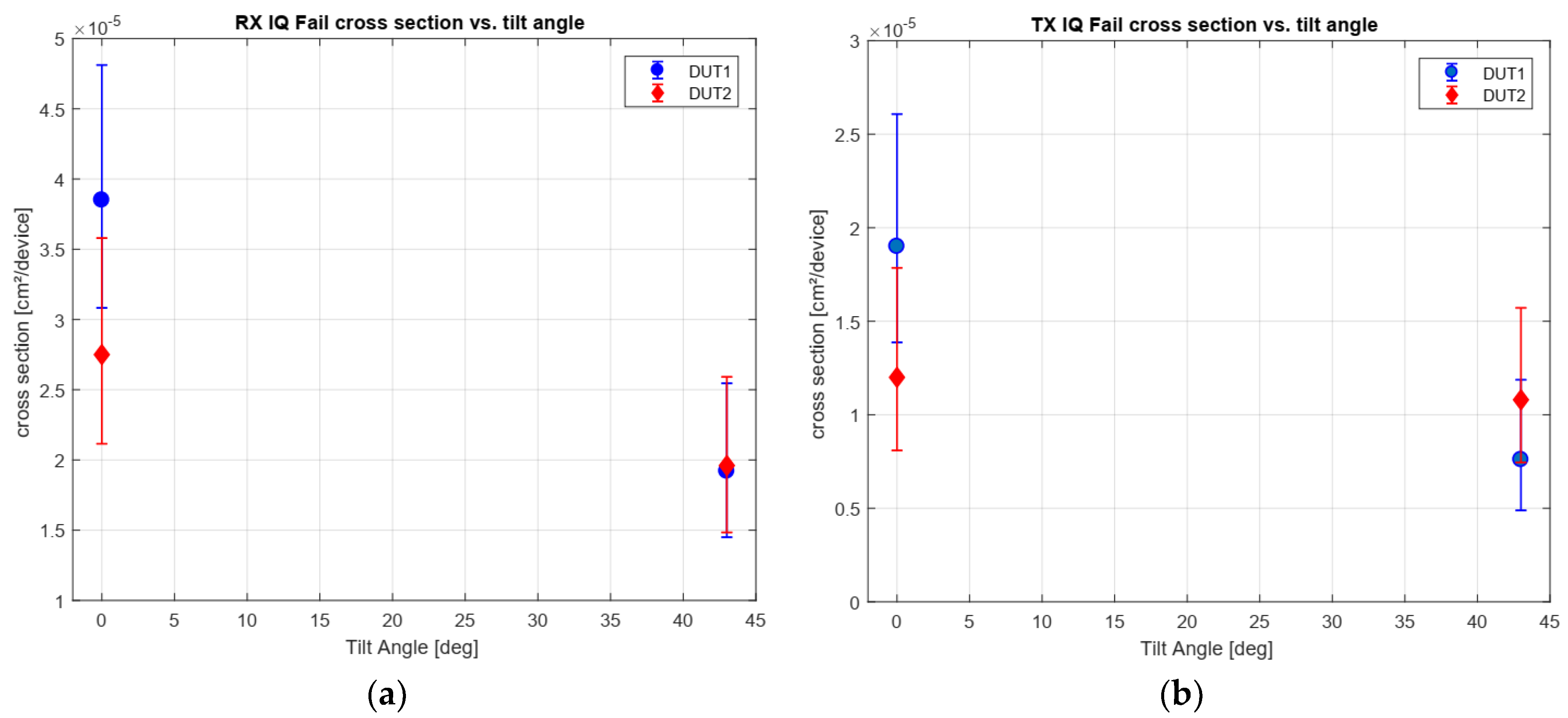
In Figure 21, the SEFI response for RX and TX IQ total failures (hard and soft IQ SEFIS combined) are represented for 0° and 43°. A third angle configuration of 60° has not been evaluated, since no higher cross section has been observed for the SEUs in the functional registers. As earlier shown, the observed SEFI cross sections differs slightly, depending on the selected tilt angle, but decreases with increased tilt angle. This is an opposite behavior as observed for the SEUs and is explained by the SEFI to SEU ratio as discussed in Section 6.4. However, like for SEUs, no tilt angle dependency can be assumed for IQ SEFIs.

6.6. LET on Active Region

Due to the different (metallization) layers, it could be possible that the LET in the active region might differ from the LET provided on the DUTs surface (Table 2). For this reason, a model has been developed in SRIM 2013 [13] to evaluate the effective LET in the active region. Due to the inhomogeneous use of the metallization layers, two scenarios are summed: (1) with all seven layers and their insulator material in between and (2) without any metallization above the sensitive volume. The layer thicknesses are derived from the FIB cross section of Figure 4. Simulations were made for all tested ion species to verify the LET and range in the die. The narrow metallization layers (3–7) have been combined to a single layer of copper. The simulation results of the stopping power in the material are presented in Figure 22 for Xe without metallization layers and in Figure 23 with all layers included. For each simulation, a long-range view (a) and a detailed view on the active region (b) are presented.
As seen for the non-metallization case, the ion range becomes longer compared to the metallization configuration until it stops. The LET in the active region is about 1500 eV/Angstrom. This equals a LET of 64.4 MeV.cm²/mg in silicon, which is a similar LET as given at the device surface.
Figure 23 shows the ion track and stopping power for the full layer configuration. In the copper metallization, the simulated LET increases to about 5000 eV/Angstrom.
The ion track for Xe becomes shorter compared to the non-metallization case and stops at about 8.2 µm. The initial ion range for Xe in silicon is usually about 73 µm (refer Table 2). In this case, the track is long enough to reach the active region of the die and induces a stopping power of about 1500 eV/Angstrom which is similar to the non-metallization case and results, also into a LET of 64.4 MeV.cm²/mg. Based on these analyses, it can be assumed that the metallization structure has no effect to the LET in the active region of the die.

6.7. Error Rate Prediction for Reference Missions

Based on the observed SEE response, an error rate prediction analysis is performed for two reference missions: (1) low earth orbit (LEO), 850 km sun-synchronous orbit with a life-time of 2 years and (2) geostationary orbit (GEO) for 15 years life-time. A 1 g/cm² solid aluminum sphere (shielding) is assumed for both reference missions. For the error rate prediction, the OMERE software (version 5.2.4) has been used [14]. The results for nominal conditions are presented in Table 4.
Error rates for worst case conditions (CREME96 model, one day solar flare) are presented in Table 5.

7. Conclusions

In this paper, the AD9361, a highly integrated RF-agile transceiver device has been tested under heavy ion irradiation. The DUT is an excellent candidate for future radio systems in NewSpace missions since it allows the integration of multiple RF applications into a single radio platform which reduces the overall mass and power consumption. Due to the DUTs complexity, a straight forward heavy ion radiation test procedure is not applicable and a specific test methodology has been designed successfully. The proposed test methodology could be applicable to other devices with such complex integrity, specifically related to the RF and digital processing domain. However, it still needs to be considered to adapt or optimize these test procedures for each individual DUT or even system under test. The DUT has been characterized in a high level of detail to its behavior under irradiation and shows a very robust response. Error rate prediction analysis shows that the device will have to recover from a fault only every 30 h, even for the worst case conditions in a solar flare. On nominal conditions, it takes years until a failure can be expected. Thus, even under radiation conditions, the DUT is definitely a candidate for long-term earth observation and also deep space missions.

Author Contributions

Design and concept, J.B.; test methodology, J.B. and M.J.; software, M.J.; test preparation, J.B. and M.J.; analysis, J.B.; data curation, J.B., M.J., A.C., R.G.A.; writing—original draft preparation, J.B.; writing—review and editing, All; supervision, R.G.A., A.K. All authors have read and agreed to the published version of the manuscript.

Funding

This research received no external funding.

Conflicts of Interest

The authors declare no conflict of interest.

References

  1. Budroweit, J. Design of a Highly Integrated and Reliable SDR Platform for Multiple RF Applications on Spacecraft. In Proceedings of the GLOBECOM 2017—2017 IEEE Global Communications Conference, Singapore, 4–8 December 2017; pp. 1–6. [Google Scholar]
  2. Budroweit, J.; Koelpin, A. Design challenges of a highly integrated SDR platform for multiband spacecraft applications in radiation environments. In Proceedings of the 2019 IEEE Topical Workshop on Internet of Space (TWIOS), Anaheim, CA, USA, 14–17 January 2018; pp. 9–12. [Google Scholar]
  3. Budroweit, J.; Jaksch, M.M. In-Situ TID Testing and Characterization of a Highly Integrated RF Agile Transceiver for Multi-Band Radio Applications in a Radiation Environment. In Proceedings of the 2019 IEEE International Conference on Wireless for Space and Extreme Environments (WiSEE), Ottawa, ON, Canada, 16–18 October 2019; pp. 1–6. [Google Scholar]
  4. Budroweit, J.; Jaksch, M.P.; Sznajder, M. Proton Induced Single Event Effect Characterization on a Highly Integrated RF-Transceiver. Electronics 2019, 8, 519. [Google Scholar] [CrossRef] [Green Version]
  5. Pu, D.; Cozma, A.; Hill, T. Four Quick Steps to Production: Using Model-Based Design for Software-Defined Radio. Analog. Dialogue 2015, 49, 1–5. [Google Scholar]
  6. AD9361 Data Sheet. Available online: https://www.analog.com/media/en/technical-documentation/data-sheets/AD9361.pdf (accessed on 6 December 2019).
  7. AD9361 Material Declaration. Available online: https://www.analog.com/media/en/package-pcbresources/material-declaration/cspbga/cspbga_10x10(bc-144-7).pdf (accessed on 6 December 2019).
  8. Single Event Effects Test Method and Guidelines, ESCC Basic Specification No. 25100; ESA: Paris, France, 2014; Issue 2.
  9. Gruermann, K.; Walter, D.; Herrmann, M.; Gliem, F.; Kettunen, H.; Ferlet Cavrois, V. SEU and MBU angular dependence of Samsung and Micron 8-Gbit SLC NAND-Flash memories under heavy-ion irradiation. In Proceedings of the IEEE Radiation Effects Data Workshop, Las Vegas, NV, USA, 25–29 July 2011; pp. 1–5. [Google Scholar]
  10. Cellere, G.; Paccagnella, A.; Visconti, A.; Bonanomi, M.; Harboe-Sorensen, R.; Virtanen, A. Angular dependence of heavy-ion effects in floating gate memory arrays. IEEE Trans. Nucl. Sci. 2007, 54, 2371–2378. [Google Scholar] [CrossRef]
  11. Zhang, H.; Jiang, H.; Assis, T.R.; Ball, D.R.; Narasimham, B.; Anvar, A.; Massengill, L.W.; Bhuva, B.L. Angular Effects of Heavy-Ion Strikes on Single-Event Upset Response of Flip-Flop Designs in 16-nm Bulk FinFET Technology. IEEE Trans. Nucl. Sci. 2017, 64, 491–496. [Google Scholar] [CrossRef]
  12. Chen, D.; Mondy, T.; Phan, A. Heavy Ion Test Report for the AD9364 RF Transceiver. Available online: https://ntrs.nasa.gov/archive/nasa/casi.ntrs.nasa.gov/20170009007.pdf (accessed on 2 December 2019).
  13. SRIM-2013 Professional Software. Available online: http://www.srim.org/ (accessed on 18 December 2019).
  14. The OMERE Software. Available online: http://www.trad.fr/en/space/omere-software/ (accessed on 20 December 2019).
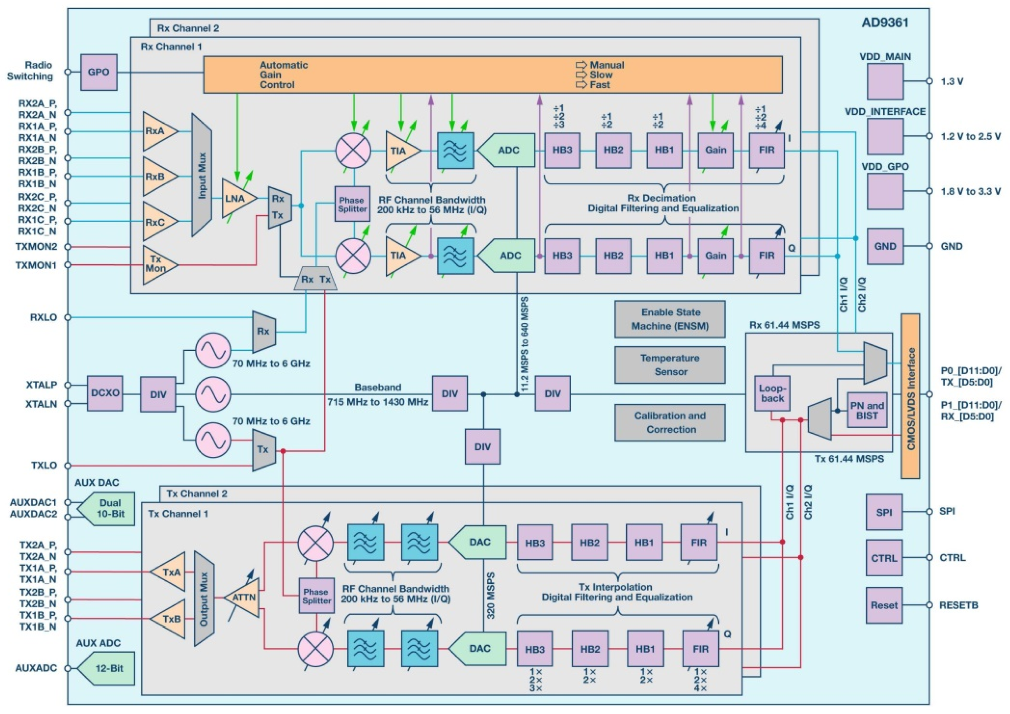
Figure 1. AD9361 functional block diagram [5].
Aerospace 07 00014 g001
Figure 2. Side view X-ray image of the AD9361 [4].
Aerospace 07 00014 g002
Figure 3. Picture of the acid-etched device under test (DUT) with exposed die and dimensions.
Aerospace 07 00014 g003
Figure 4. Focused ion beam (FIB) cross section of the die with the measured thickness.
Aerospace 07 00014 g004
Figure 5. Picture of the test board for the heavy ion test with the acid etched DUT on the right-hand side.
Aerospace 07 00014 g005
Figure 6. Heavy Ion test setup schematic at UCL/HIF.
Aerospace 07 00014 g006
Figure 7. AD9361 heavy ion test flow chart.
Aerospace 07 00014 g007
Figure 8. Reference curve with its boundaries for the in-phase/quadrature (IQ) data validation with a Soft IQ single event functional interrupts (SEFI).
Aerospace 07 00014 g008
Figure 9. Single event upsets (SEU) cross section (a) SEU and (b) multiple bit upsets (MBU) cross section for both DUTs with a corresponding Weibull fitting curve (W = 29.43, S = 1.63).
Aerospace 07 00014 g009
Figure 10. SEFI cross sections for (a) re-configuration and (b) re-initialization events with their corresponding Weibull fitting curve (W = 27.15, S = 1.44).
Aerospace 07 00014 g010
Figure 11. SEFI cross sections for re-initialization events based on (a) hard IQ failures on the receiver chain and (b) hard IQ failures on the transmitter chain (W = 34.84, S = 1.743).
Aerospace 07 00014 g011
Figure 12. SEFI cross sections for re-initialization events based on (a) soft IQ failures on the receiver chain and (b) soft IQ failures on the transmitter chain (W = 30.50, S = 1.809).
Aerospace 07 00014 g012
Figure 13. Current conditions during irradiation showing a high current state in (a) and several events and their recovery processes in (b).
Aerospace 07 00014 g013
Figure 14. Soft IQ SEFI on channel 1 (I1/Q1) of the DUT 2 receiver, showing an SEU in the ADC data.
Aerospace 07 00014 g014
Figure 15. Soft IQ SEFI on channel 1 (I1/Q1) of the DUT 1 receiver, showing a glitch in the data which recovers itself after 15–20 samples.
Aerospace 07 00014 g015
Figure 16. Hard IQ SEFI on channel 2 (I2/Q2) of the DUT 1 transmitter, showing total loss of the IQ data.
Aerospace 07 00014 g016
Figure 17. Hard IQ SEFI on channel 1 (I1/Q1) of the DUT 2 receiver, showing an amplified waveform which still contains its initial frequency.
Aerospace 07 00014 g017
Figure 18. Accumulated SEUs vs. monitored functional registers for DUT 1 on four runs (Cr 0°, Rh 0°, Rh 43°, and Xe 0°).
Aerospace 07 00014 g018
Figure 19. Accumulated SEUs and register dependencies for the monitored functional registers on DUT 1 with Xe 0°.
Aerospace 07 00014 g019
Figure 20. Tilt angle dependency for (a) SEUs on DUT 1 and DUT 2 at a LET of 62.5 MeV.cm²/mg with Xe on 0°, Rh on 43°, and Cr on 60° tilt angle.
Aerospace 07 00014 g020
Figure 21. Tilt angle dependency for (a) TX and (b) RX IQ SEFIs (Hard and Soft in total) at a LET of 62.5 MeV.cm²/mg with Xe 0° tilt angle and Rh on 43° tilt angle.
Aerospace 07 00014 g021
Figure 22. Effective LET in the different layers of the DUT for Xe (refer FIB cross section of Figure 4). (a) shows the long track of the ion stopping power and (b) a detailed view on the active silicon area of the DUT.
Aerospace 07 00014 g022
Figure 23. Effective LET in the different layers of the DUT for Xenon (refer FIB cross section of Figure 4). (a) shows the long track of the ion stopping power and (b) a detailed view on the active silicon area of the DUT.
Aerospace 07 00014 g023
Table 1. Part and test information table.
Sample NumberTest Board IDFull Part NumberLot Date Code (LDC)Part Serial NumberFabrication Site
101AD9364BBCZ#13502769606.1Singapore
202AD9364BBCZ#13502769606.1Singapore
Table 2. Ion, linear energy transfer (LET), range and flux based on the Catholic University of Louvain (UCL) heavy ion facility (HIF) specification.
Ion TypeIon ElementEnergy on DeviceRange on Device (Si)LET on DeviceAdjustable Flux
(MeV)(um)(MeV.cm²/mg)(#/cm²/s)
Neon22Ne7+2382023.3<1 × 101 to 1.5 × 10⁴
Chrom53Cr16+505105.516.1<1 × 101 to 1.5 × 10⁴
Krypton84Kr25+76994.232.4<1 × 101 to 1.5 × 10⁴
Rhodium103Rh31+95787.346.1<1 × 101 to 1.5 × 10⁴
Xenon124Xe35+99573.162.5<1 × 101 to 1.5 × 10⁴
Table 3. SEU vs. Hard IQ SEFIs for DUT 1.
IonLET (MeV.cm²/mg)SEUs (#)IQ Hard SEFIs (TX + RX) (#)SEFI/SEU Ratio (%)
Ne3.30936 + 815.1
Cr16.003756 + 155.6
Kr32.003959 + 145.9
Rh46.004226 + 83.3
Xe62.5045410 + 145.3
Table 4. Error rates for two references missions and the observed SEEs (launch date: 1st December 2019) under nominal conditions.
OrbitSEE TypeHeavy Ion SEE Rate (failure/device/day)Years for Failure
LEOSEU3.98 × 10−46.88
GEOSEU1.17 × 10−32.34
LEOSEFI re-config.2.22 × 10−5123
GEOSEFI re-config.6.43 × 10−543
LEOHard RX IQ SEFI1.26 × 10−5217
GEOHard RX IQ SEFI3.77 × 10−573
LEOHard TX IQ SEFI1.55 × 10−5176
GEOHard TX IQ SEFI4.64 × 10−561
Table 5. Error rates for two references missions and the observed SEEs (launch date: 1st December 2019) for worst case conditions (one day solar flare).
OrbitSEE TypeHeavy Ion SEE Rate (failure/device/day)Hours for Failure
LEOSEU3.06 × 1007.78
GEOSEU1.33 × 1011.8
LEOSEFI re-config.2.02 × 10−1120
GEOSEFI re-config.8.79 × 10−127.4
LEOHard RX IQ SEFI6.50 × 10−2370
GEOHard RX IQ SEFI2.84 × 10−185
LEOHard TX IQ SEFI6.19 × 10−2387
GEOHard TX IQ SEFI3.11 × 10−177