Review

A Review of Low-Power Electric Propulsion Research at the Space Propulsion Centre Singapore

by
George-Cristian Potrivitu
1,*,
Yufei Sun
1,
Muhammad Wisnuh Aggriawan bin Rohaizat
1,
Oleksii Cherkun
1,2,
Luxiang Xu
1,2,
Shiyong Huang
1 and
Shuyan Xu
1
1
Plasma Sources and Applications Centre/Space Propulsion Centre, National Institute of Education, Nanyang Technological University, Singapore 637616, Singapore
2
Center for Space Propulsion and Gravitational Universe (SPaGU), Hang Zhou Institute for Advanced Studies, University of Chinese Academy of Sciences, Hang Zhou 310024, China
*
Author to whom correspondence should be addressed.
Aerospace 2020, 7(6), 67; https://doi.org/10.3390/aerospace7060067
Submission received: 20 April 2020 / Revised: 10 May 2020 / Accepted: 26 May 2020 / Published: 28 May 2020
(This article belongs to the Special Issue Electric Propulsion)

Abstract

:
The age of space electric propulsion arrived and found the space exploration endeavors at a paradigm shift in the context of new space. Mega-constellations of small satellites on low-Earth orbit (LEO) are proposed by many emerging commercial actors. Naturally, the boom in the small satellite market drives the necessity of propulsion systems that are both power and fuel efficient and accommodate small form-factors. Most of the existing electric propulsion technologies have reached the maturity level and can be the prime choices to enable mission versatility for small satellite platforms in Earth orbit and beyond. At the Plasma Sources and Applications Centre/Space Propulsion Centre (PSAC/SPC) Singapore, a continuous effort was dedicated to the development of low-power electric propulsion systems that can meet the small satellites market requirements. This review presents the recent progress in the field of electric propulsion at PSAC/SPC Singapore, from Hall thrusters and thermionic cathodes research to more ambitious devices such as the rotamak-like plasma thruster. On top of that, a review of the existing vacuum facilities and plasma diagnostics used for electric propulsion testing and characterization is included in the present research.

1. Introduction

The deployment of large low-Earth orbit (LEO) satellite constellations became reality in the past couple of years, with hundreds of small satellites being placed on LEO [1,2]. It came with no surprise when the mission planners opted for electric propulsion as main propulsive system of their satellites. Proved to offer a drastic reduction in fuel consumption, compared to chemical propulsion systems, and capable of firing for long time intervals with high system fault tolerance, the electric propulsion systems seemed to be ideal for LEO small satellite missions, thus, increasing interest in developing efficient and reliable electric propulsion systems.
The space sector, and mainly the satellite telecom sector, shows an increasing interest in solar electric propulsion as propulsion systems for attitude determination and control systems (ADCS) and even as main propulsion system (orbit control). The rapid expansion of the solar electric propulsion domain came after the recognition of the successful interplanetary missions run by various space agencies which proved the reliability and the excellent versatility of those devices. High power electric propulsion thrusters have been developed in the range of 2–5 kW, such as the PPS1350-E and PPS5000 by Snecma, the T6 by QinetiQ, RIT-22 by ArianeGroup, and the HEMPT3050 (High Efficiency Multistage Plasma Thruster) by Thales Alenia Space. Commercial companies have already launched all-electric satellite platforms on geostationary orbit (GEO), such as Boeing’s 702SP platform [3], the fist high-power all-electric telecom satellite in the world, EUROSTAR3000EOR platform by Eutelsat and Eurostar NEO by SES [4,5]. GSAT-4, an Indian satellite, marks a first for the Asian telecom and navigation market with the first GEO platform equipped with four Hall thrusters [6], although the satellite failed to reach its orbit due to launch vehicle malfunction. The GSAT-9 mission was a success with the four Hall thrusters being used for station keeping and orbit control [7]. LEO constellations, like the one proposed by OneWeb and SpaceX’s Starlink, are planned to have hundreds of satellites deployed for internet coverage, all equipped with electric propulsion thrusters [8]. As of April 2020, Starlink constellation already has 422 satellites equipped with krypton-fed Hall thrusters [9], while OneWeb’s 76 satellites operate low-power xenon-fed Hall thrusters [1]. 
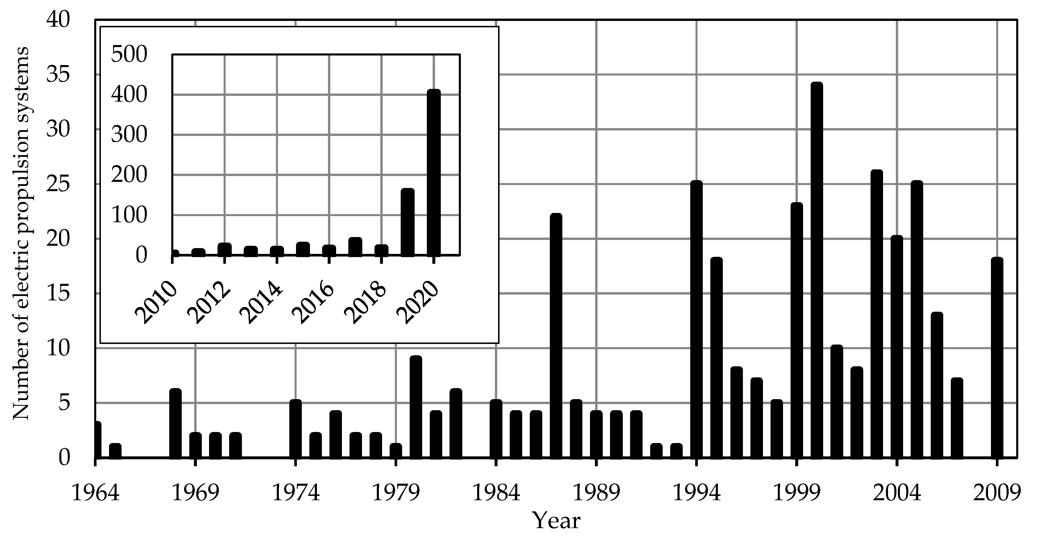
Figure 1 depicts the approximate number of electric propulsion systems that were deployed in space since 1964 until today. It is worth noticing that only in the past 10 years the number of electric propulsion systems more than doubled, compared to the first 45 years, and this can be explained by the large number of satellites with electric propulsion deployed by SpaceX and OneWeb. Furthermore, almost 80% of the total electric propulsion systems launched accounts for Hall thrusters, while 10% for ion engines.
Most of the systems counted in Figure 1 are high-power systems as they are the best choice for GEO missions, for both station keeping and orbit insertion, and for interplanetary travel. On the other hand, low-power electric propulsion systems can be employed for low orbit missions and small form-factor platforms (of a few units, 1U = 10 cm × 10 cm × 10 cm), 1–500 kg [11]. Such satellites would need thrusts up to several mN, and since the main tasks for such propulsion systems would be to compensate drag, ADCS and collision avoidance maneuvers, orbital phasing, and formation flying, they will need to produce a high delta-V. Another possible mission that will require a thruster would be the controlled deorbit at the end of life. For ADCS purposes, field emission electric propulsion (FEEP) systems, vacuum arc thrusters (VAT), pulsed plasma thrusters (PPT), or arcjets have been already extensively used. A first successful commercial in-orbit demonstration of a FEEP system for a 3U satellite was achieved in 2016 by Planet Labs’ Flock-3p satellite with IFM Nano from Enpulsion [12]. However, in the range of 50 W to 100 W the Hall thruster technology can be the perfect candidate for the job of producing relatively high thrusts with high efficiencies, allowing them to be used as a main propulsive system as well as an ADCS, thus, offering both off-orbit and in-orbit autonomy.
Low-power Hall thrusters with classical designs are known to lose thrust efficiency and specific impulse once the input power is lowered. A few innovative designs have been considered to overcome this drawback, including the wall-less technology and the magnetically shielded thrusters. Nevertheless, the cathode remains an instrumental component of a Hall thruster, and as the power level drops, such thermionic emitters would be required to sustain and neutralize a current usually under 1 A. Therefore, the development of low-current cathodes, working in self-sustained mode while consuming external power only during the startup, remains a priority for many electric propulsion research and industrial entities.
At the Plasma Sources and Applications Centre/Space Propulsion Centre Singapore (PSAC/SPC), research on electric propulsion encompasses topics such as low-power Hall thrusters, low-current thermionic cathodes and material processing [13,14,15]. Several classes of Hall thrusters have been designed, manufactured, and operated in the range of 5 to 200 W, while 1 A-class thermionic cathodes were developed to work with the Hall thrusters and have been studied in order to understand the discharge mode transition as well as to construct scaling laws for such devices. Harnessing the knowledge on the rotamak fusion device, at PSAC/SPC, substantial numerical and experimental research is dedicated to the conversion of the rotamak device into an electrodeless plasma thruster. To sustain the research in the field of electric propulsion, several vacuum test facilities of various sizes have been designed and set up, from small (<0.3 m3) chambers primarily for cathode studies to the Space Environment Simulation Chamber (SESC), a 19.7 m3, 4.75 m long vacuum test facility used for Hall thruster and cubesat research [16,17]. An innovative thrust stand was developed and installed in SESC, while a series of plasma diagnostics, including optical emission spectroscopy (OES), retarding potential analyzers (RPA), Hall probes, Faraday cups, and Langmuir probes were used to characterize plasma properties in the plumes of Hall thrusters, thermionic cathodes, as well as rotamak devices. The following sections introduce and discuss each of the aforementioned facilities, devices, and plasma diagnostics together with selected experimental results.

2. Vacuum Test Facilities and Plasma Diagnostics

Previous studies showed that the vacuum facility can impact the performance of the electric propulsion devices such as Hall thrusters and emissive cathodes [18,19,20,21]. A larger vacuum facility, with its walls as far away from the plasma plume, is hence desired. At PSAC/SPC a continuous effort was invested in the development of a large-scale vacuum facility to meet the purpose of Hall thruster and cubesat testing.

2.1. Space Environment Simulation Chamber

The Space Environment Simulation Chamber or Plasma Space Actuation Chamber is a cylindrical chamber that is 4.75 m long and 2.3 m in diameter, see Figure 2a. The background pressure inside the chamber can reach 10 6 Pa and is achieved using four turbomolecular and cryogenic pumps fully integrated into an automatic system for vacuum control readout and pump activation/purge sequence. The chamber is equipped with a multitude of electrical feedthroughs and optical diagnostics portholes. Its sheer size allows for testing of fully assembled cubesats with propulsion modules attached which makes the chamber the flagship space environment simulation facility in Southeast Asia.
The most important and permanent fixture to the chamber is the fully suspended quadfilar thrust measurement platform, which is presented in Section 2.3. Apart from the thrust measurement system, the chamber can accommodate multiple diagnostics for a complete plasma characterization of the Hall thrusters and cathodes. Such diagnostics include Faraday cups, retarding potential analyzers, and Langmuir probes, all integrated into an automated remote-controlled system.

2.2. Cathode Experiments Vacuum Chamber (CEVAC) and Thruster Experiments Vacuum Chamber (TEVAC)

Two small scale vacuum chambers are used primarily for cathode and low-power Hall thruster research. Figure 2b depicts the Cathode Experiments Vacuum Chamber (CEVAC). The vessel was previously used for material plasma processing studies and retrofitted to accommodate cathode testing in standalone mode. The chamber is a cylinder with a diameter of 0.4 m and a height of 0.3 m. CEVAC is equipped with a dry rotary pump and a 600 l·s−1 turbomolecular pump assuring a pressure inside the chamber of down to 5 × 10 4 Pa-N2. To access the chamber, a hatch 0.4 m in diameter can be removed from the top.
The Thruster Experiments Vacuum Chamber (TEVAC), see Figure 2c, is a medium size vacuum facility with a capacity of 275 l. The 1 m long and 0.65 m wide chamber is made of stainless steel and its interior can be accessed via a hatch located at the top of the chamber. TEVAC is primarily used for low-power Hall thruster lifetime testing as well as for cathode testing in standalone mode or when coupled with Hall thrusters. The chamber’s rotary pump, turbomolecular pump, and two 4000 l·s−1-N2 cryogenic pumps (with typical surface temperatures of 13 K) can ensure a pressure inside the chamber of 4 × 10 4 Pa-N2. Both the CEVAC and the TEVAC are equipped with observation windows, which provide view access to the chambers’ interiors, as well as several power, gas, and thermocouple feedthroughs. Diagnostics such as Langmuir probes, Faraday cups, and OES were installed in the two chambers.

2.3. Thrust Measurement System and Plasma Diagnostics

2.3.1. Quadfilar Thrust Pendulum

For electric propulsion thrusters, an important performance parameter is the thrust,   T , which can be further used in the definition of other related parameters such as the specific impulse, I s p , and the thrust efficiency,   η T . Figure 3 depicts the schematic of the thrust measurement system installed in the Space Environment Simulation Chamber. The system contains a suspended stage that has four torsional wires fixed to the top of the chamber. The Hall thruster system can be fully mounted on the suspended stage. The movement of the stage is measured by a high-resolution optoNCDT 1450 laser displacement sensor (LDS) mounted parallel to the axis of rotation of the stage when the thruster is fired. The measurement range of the LDS is up to 20 mm with a reproducibility of 2 μm at a rate of 2 kHz. The quadfilar thrust pendulum comes with an integrated calibration unit and null measurement unit. The calibration unit is composed of fine weights (copper loops) attached to a 4 μm diameter polyamide fiber connected directly to the rear of the Hall thruster anode. The system is actuated by a high-resolution stepper motor, while a Teflon bar serves as a pivoting point.
To independently verify the thrust measurements, a similar method of horizontally translated force from hanging weights is used by the null measurement unit. A line with fine weights is connected to the stage and actuated by a high-resolution stepper motor. The null measurement system is operated while the thruster is being fired.
The thrust can be computed by knowing the LDS baseline voltage,   V b a s e , i.e., prior to firing the thruster, the voltage measured by the LDS when the thruster is firing,   V m , and the sensitivity parameter,   S , obtained from the gradient of the calibration curve [22]:
T = S ( V b a s e V m ) .
An example of a calibration curve is presented in Figure 4a. Typical low-power Hall thrusters developed at PSAC/SPC yield a thrust in the range of 2–4 mN. The calibration starts by lowering a fine weight and waiting for the voltage output of the LDS to stabilize. The sequence is repeated 10 times with all the weights being used to cover a force range up to 5.5 mN. Several curves are then registered to ensure repeatability. In Figure 4a, a linear dependency is observed between the output voltage and the calibrated force, while the sensitivity parameter S can be computed as the inverse of the calibration factor, in this case S = 0.567 mN·V−1. It is worth stating that the sensitivity of the quadfilar thrust pendulum depends on the resolution of the LDS as well as the torsional wires’ stiffness. This last parameter can be altered using fine tuners and resonant frequency analysis for the wires. Moreover, the calibration system allows for in situ calibration process, under vacuum conditions before, during, and after the test to ensure that thermal effects on the materials are taken into account by closely observing the changes in the calibration sensitivity values. The system allows for a thrust resolution of 1 μN, while the measurement uncertainty remains below 10%.
The null measurement unit is triggered once the output of the LDS stabilises, i.e., the quadfilar stage stops oscillating and reaches an equilibrium steady state displacement. The stepper motor pulls the quadfilar stage back to the initial location before firing and stops once LDS detects that the stage is back at the initial location. The system computes the thrust needed as an independent value.
Figure 4b–d shows the performance parameters of a 200 W-class Hall thruster with a hybrid magnetic system, i.e., containing both magnetic coils and permanent magnets, developed at PSAC/SPC. The thruster is operated with Kr at power levels under 130 W and for anode mass flow rates ranging from 0.24 to 0.34 mg·s−1 (3.9 to 5.5 sccm). The thrust shows a linear dependency with the applied power, with higher thrust for higher discharge power, as depicted in Figure 4b. At a discharge power above 80 W, the thrust is increasing with the anode mass flow rate. For the range of discharge power and mass flow rates tested, the thrust varies between 3.2 and 5.25 mN. The specific impulse dependency on discharge power is shown in Figure 4c. A linear dependency is observed, with significantly higher specific impulse at lower anode mass flow rates, since this parameter is inversely proportional to the propellant mass flow rate. The thrust efficiency, depicted in Figure 4d, presents a slightly increasing trend over the range of discharge power, with higher values for lower mass flow rates. At 110 W and 0.24 mg·s−1-Kr the thruster reaches an efficiency of over 25% for a thrust level of 4.25 mN and a specific impulse of 1225 s.

2.3.2. Plasma Diagnostics for Electric Propulsion Systems

Apart from the thrust measurements, knowing the plasma properties of the discharge plumes of electric propulsion systems bolster the physical understanding of such devices and the optimization efforts. Both invasive and non-invasive plasma diagnostics are developed and used at PSAC/SPC to characterize the plumes of low-power Hall thrusters, low-current cathodes, and the rotamak. The main intrusive plasma probes are known as the automated integrated robotic systems (AIRS) [22] containing interchangeable Langmuir probes, Faraday cups, and retarding potential analyzers. The probes are actuated and controlled by Arduino microcontrollers to allow for spatially resolved measurements, while data are collected and processed in real-time via computer programs. Arduino microcontrollers proved to be suitable for vacuum environments and were previously tested in space [23] and used for Langmuir probe measurement systems [24].
Faraday probes are employed to measure the ion current density spatial distribution, providing valuable information about the divergence of the Hall thruster and total ion current related to the ionization efficiency. Copper and tungsten are used as collector and guard ring material which are separated by an alumina tube, while the collected ion current density is derived from the collected probe current [25]. The collector has a typical size of 1 mm × 1 mm. Ion current density profiles in the plume of a low-power Hall thruster are depicted in Figure 5a. The thruster is operated with Kr at two discharge powers of 110 and 140 W. The measurements showed that the higher the discharge power, the larger the full width at half maximum (FWHM) of the distribution. The FWHM of the distribution can provide information about the level of collimation of the thruster plume, strongly related to the divergence angle. Moreover, higher discharge power translates in a higher distribution maximum for the same mass flow rate. This latter trend can be attributed to a higher ionization level at higher discharge power. Another study was conducted with the same thruster and results for two discharge voltages V 1 = 150   V and V 2 = 200   V and anode Kr mass flow rates from 0.24 mg·s−1 to 0.3 mg·s−1 (3.9 to 4.8 sccm) were presented [25]. The influence of the discharge voltage and mass flow rate can be noticed on two characteristics of the ion current density distributions. First, the study showed that at a constant discharge voltage the distribution maximum increases as the propellant flow rate increases, since more gas is available for ionization within the discharge channel. Secondly, for the lower voltage V 1 , as the mass flow rate was increased the FWHM increased as well. A reverse of the effect was observed at the higher discharge voltage   V 2 . Here, the beam seemed more collimated for the highest mass flow rate. The same study reported that at a lower discharge voltage, the ion current density peak is saturated at the lower mass flow rates, while an increase in the discharge voltage can push the saturation threshold towards the upper level of the mass flow rate. In both cases, the finite discharge voltage did not allow for further ionization although more propellant was injected in the discharge channel.
Other invasive plasma diagnostics developed at PSAC/SPC include cylindrical Langmuir probes [26,27] for plasma density, electron temperature, plasma potential measurements, and four-grid miniaturized RPAs (0.5 cm × 4.5 cm) employed in Hall thrusters’ plumes to map the ion energy distribution functions [22]. Hall effect probes built in-house are extensively employed when characterizing the magnetic field topology and the rotating magnetic field in the rotamak devices. Such measurements help in understanding the physics of the rotamak at different operational points and support the PSAC/SPC endeavor in translating the rotamak technology to applications in electric propulsion.
Non-invasive plasma diagnostic methods offer the advantage of minimal to no interaction with the plasma, thus, reducing the perturbations induced into the system operation by the diagnostics. The simplest and most insightful diagnostic procedure is to monitor the time variation of the discharge electrical parameters, such as the discharge current and potential. Transforming the temporal variation of the two parameters into power spectral density profiles allows for the identification of the main oscillating phenomena in the plasma plume. Such phenomena can be linked with physical processes that can take place during the Hall thruster and cathode discharges, such as the emergence of predator–prey ionization instabilities, leading to plume mode for cathodes [28,29,30], or breathing mode for Hall thrusters [31,32]. More on how such measurements via Rogowski coils and voltage probes can offer valuable information about the cathode discharge is presented in Section 4.
At PSAC/SPCS, a quadrupole mass spectrometer (QMS) is employed as a non-invasive plasma diagnostic in the TEVAC during endurance testing for low-power Hall thrusters [33]. The QMS monitors the spectral lines that may correspond to electronic transitions of contaminant species due to erosion, such as copper, stainless steel, refractory metals (anode), LaB6 (cathode emitter), graphite, or ceramics (alumina, boron nitride).
Optical emission spectroscopy (OES) is also employed for Hall thrusters and cathodes plasma discharge diagnostics. Collimator lenses collect light emitted from specific locations in the plumes and direct it via fiber optic cables to a CCD UV/VIS/NIR spectrometer. The emission spectrum of the discharge can be monitored in real time via a computer software. Furthermore, OES can be a very valuable tool when different propellant mixtures are used for the thruster and cathode. An example of the integrated optical emission intensity in the range 300 nm to 1100 nm for a Hall thruster plume operating at two discharge voltages and several Kr mass flow rates is presented in Figure 5b, while an example of the raw emission spectra in near-infrared from the same thruster, but when operating with Xe, is shown in Figure 5c. The results are in good agreement with the data collected by the Faraday probe, proving that higher intensities at higher discharge voltages translate into higher ionization rates. Moreover, the saturation process at the discharge voltage V 1 = 150   V can also be observed, as the emission intensity increases with increasing mass flow rates until it reaches a plateau at higher mass flow rates. It is worth noting that OES combined with a collisional–radiative model (CRM) for Xe and Kr can provide information about the electron temperature and density in the plumes of Hall thrusters [34,35,36,37] and cathodes [38,39]. Real-time OES at high acquisition frequencies may be employed for cathode mode transition monitoring and offer insights on changes in plasma properties during the transition from spot to plume and vice versa.

3. Hall Thrusters: Development and Testing

The primary focus of the research at PSAC/SPC is the development of low-power Hall thrusters that can be used for small satellite platforms. Designing efficient low-power Hall thrusters has been an arduous process and research teams quickly realized that a miniaturized classical geometry of the thruster and the reduction in discharge power comes with a significant drop in thrust efficiency [40,41]. At PSAC/SPCS, three classes of Hall thruster have been developed spanning from several watts to hundreds of watts while producing a thrust from μN to mN range. Naturally, the development of Hall thrusters compelled the development of low-current cathodes, which is discussed in Section 4. The thrusters and cathodes are operated with Ar, Kr, and Xe and their performances are assessed using the diagnostics described in the previous sections. The latest class of Hall thrusters presented in Section 3.3 is an innovative concept that eliminated the need of an active, external electron emitter, while operating at high discharge voltages.

3.1. 200 W-Class Hall Thrusters

The first class of Hall thrusters developed at PSAC/SPC is a 200 W-class Hall thruster. The thruster has a classical design with a ceramic discharge channel and is operated with an external thermionic electron emitter. The first iteration of the thruster design employed a hybrid magnetic system with internal permanent magnets and external coil. The thruster operating with Xe together with the first design of the PSAC 1 A-class cathode is depicted in Figure 6a.
The second iteration of the thruster employed electromagnetic coils for both the internal and external magnetic circuit. In general, at low discharge power levels, the magnetic field can be generated only by the internal coil which requires 1 W of power on average. However, at higher discharge power levels, both the internal and external magnetic coils are used with an average power of 3 W. The upgraded thruster with the new generation of the PSAC cathode is presented in Figure 6b. Moreover, a schematic of the thruster is shown in Figure 6c.
The thruster can stably fire at discharge potentials from 110 to 270 V with mass flow rates ranging from 0.3 to 0.7 mg·s−1 (3 to 7.1 sccm), leading to an anode power from 50 to 220 W for Xe. Some of the thruster performance results when running with Kr are presented in Figure 4b–d [16]. When operating with Xe and at 200 W of discharge power, the thruster can yield a thrust of 9.34 mN and a specific impulse of 1729 s, while the thrust efficiency is 39.3% [42]. A picture of the thruster plume at this operational point is depicted in Figure 6d. At 100 W, when operating with Xe, the thruster produces a thrust of 5 mN with a specific impulse of 940 s, at a thrust efficiency of 23.4% [42].

3.2. 25 and 50 W-Class Hall Thrusters

At PSAC/SPC a continuous effort was dedicated to the development of Hall thrusters with a power consumption level below 100 W and aiming at a thrust level below 5 mN. Such low-power levels can induce a rapid loss in the thrust efficiency, which can be prevented with innovative propellant distribution inside the discharge channel and manipulation of the magnetic field topology.
Two classes of thrusters have been developed and tested: (a) 25 W nominal discharge power—a thruster with an outer discharge channel diameter of 24 mm, depicted in Figure 7a; (b) 50 W nominal discharge power—a thruster with an outer discharge channel diameter of 30 mm, presented in Figure 7b. The thrusters were designed employing a classical geometry configuration with ceramic discharge channels, while the significant improvement was made in gas distribution and the outer magnetic field topology in order to improve operation at low mass flow rates in the range of 0.1 to 0.5 mg·s−1-Xe (1 to 5.1 sccm) and within a high discharge voltage range of 200 to 300 V. The magnetic field is created by two electromagnetic coils, which are connected in series with the discharge power supply to reduce the number of power sources needed to operate the thruster.
Thruster performance evaluation is ongoing, and first in-space tests of the propulsion system based on the thrusters are scheduled in the last quarter of 2020. When operating at ~50 W, the thruster delivers 3 mN of thrust with an efficiency of 25.2%. Both thrusters operate with a BaO impregnated tungsten miniature dispenser cathode to reduce the overall propulsion system power consumption.

3.3. Cathodeless Hall Thrusters

Cathodeless Hall Effect Microjet Thruster is a flight proven thruster developed in PSAC/SPC and launched on board of a ~200 kg microgravity satellite, Taiji-1 [43,44]. Experimental measurements showed that the thruster can provide a wide thrust range of 1 to 100 µN with a resolution of 100 nN and extreme thrust stability in the frequency range of 0.01 to 1 Hz, consuming up to 5 W of power at high discharge voltages (~2000 V). The thruster has a magnetic system formed of permanent magnets and a narrow discharge channel. Plume neutralization is achieved passively using low work function materials placed at some locations on the thruster. A combination of multiple thrusters shall be used for space-based drag-free experiments to compensate the effects of solar radiation, atmosphere drag, tidal, and other non-conservative forces exerted on the spacecraft. Figure 8a presents the thruster operating with synthesis gas, while Figure 8b,c depicts the thruster firing in SESC with Xenon during the developmental and qualification campaigns.

4. Thermionic Cathodes for Hall Thrusters

Hall and ion thrusters rely on electron emitters for discharge maintenance as well as plume neutralization. Other electric propulsion systems, such as FEEP, employ electron emitters only for neutralization purposes. Thermionic cathodes are devices that supply the electrons needed for the aforementioned tasks and are a crucial part of the electric propulsion system. The core of a cathode is the emitter, or the insert made of low work function materials. To emit the required electron current, the emitter needs to reach a certain temperature level, dictated by the Richardson–Dushman equation [45]. This temperature can be reached via active external heating of the emitter, i.e., through a heating element surrounding the emitter, or solely via the emitter region plasma, i.e., electron and mainly ion current heating. The cathode can be started by applying enough heating power to reach a certain level of electron emission, i.e., hot cathode ignition [46], or through an electrical breakdown between, i.e., cold cathode ignition. The latter cathodes do not employ an external heater and are known as heaterless cathodes [47].
The main geometrical parameters of a hollow cathode are presented in Figure 9. The core of a cathode is the emitter which can be shaped as a cylinder or a pallet. In the case of cylindrical emitters, their internal diameter,   D e , and length, L e , define the total emission surface area. The orificed cathodes are characterized by the orifice diameter,   D o , and length,   L o , while the orifice aspect ratio,   A R o = L o / D o , is an important parameter that impacts the internal pressure of the device and the internal plasma properties. Some hollow cathodes do not have an orifice plate, and they are known as orifice-less cathodes. The cathode–keeper distance,   L C K , defines the emitter–keeper gap and plays an important role during the cathode startup, when the keeper potential extracts the electrons from the internal plasma out through the cathode orifice at supersonic velocities. The emitter shape, the existence of the cathode orifice, and the cathode–keeper distance are the main parameters that define the potential distribution and the intensity of the electric field inside the cathode. Next, the keeper orifice diameter,   D K , and length, L K , and the aspect ratio, A R K = L K / D K , are of high importance especially for the orifice-less cathodes, imposing the internal pressure. The electrons that are exiting through the orifice, extracted by the external anode, reach supersonic flow that is large enough to allow for deviations from the equilibrium electron energy distribution function (non-Maxwellian EEDF), leading to the emergence of plasma turbulence and instabilities in the plume [45,46,48].
In the space sector the paradigm changed from the very big satellite platforms to progressively smaller platforms [1,10,49]. A smaller platform means less power available. Therefore, the challenge is in designing electric propulsion systems that can consume increasingly less power, being very efficient at the same time. A quick calculation reveals that a 50 W Hall thruster imposes, ideally, a discharge current of around 0.2 A. Therefore, such a thruster will require a cathode that is capable of emitting a current below 1 A and should not require more than 50 W during the heating time. In order not to impact the thruster performance and efficiency, the cathode should require a very low propellant flow rate and also should operate stably, in a self-sustained mode, namely, after the thruster is ignited and the cathode heating is turned off. For the emitter material, lanthanum hexaboride (LaB6) remains the preferred choice. However, its relatively high work function [45] imposes higher operational temperatures and more power consumption. Therefore, the thermal management of such devices is crucial. When it comes to materials for the parts of the hollow cathode, a few choices are available, due to material incompatibility at high temperature [30,45,46]. Refractory metals (tungsten, molybdenum, tantalum, rhenium-tungsten alloys, and tantalum-zirconium-molybdenum alloys) are preferred as well as high temperature ceramics (alumina-Al2O3, boron nitride-BN) and graphite [49].
At PSAC/SPC, low-power thermionic cathodes are developed to work together with the low-power Hall thrusters. Another important aim of the cathode research is to understand the physics that govern their operation which is instrumental and greatly bolster the attempts of device design optimization by testing the cathodes in standalone mode. Although thermionic cathodes present a rather simple geometry, they produce flows that span across a wide range of aspects in plasma physics and fluid mechanics. From a cold propellant flow, through a partially ionized gas, to a compressible viscous flow and supersonic electrons as well as plasma micro-turbulences in the plume, cathodes are the perfect test benches for plasma physics, raising some of the most important challenges in the field of electric propulsion. The cathodes developed at PSAC/SPC are based on LaB6 hollow cylindrical emitters which are brought to initial thermionic emission via a heated element [25]. The cathodes are designed to produce emission currents below 1 A, while relying on low heating power [25,50]. New emitter designs allowed for a reduction in startup power consumption and self-sustained operation with low-power Hall thrusters.

4.1. PSAC 1 A-Class Cathode

PSAC 1 A-class cathodes are based on a LaB6 hollow cylindrical emitter with an emission surface area of 0.63 cm2. The emitter region continues with the orifice region formed by a 0.55 mm thick LaB6 plate with a 1 mm orifice. The emitter orifice plate has an emission surface area of 0.13 cm2, increasing the total emission surface area of the cathode to 0.76 cm3. A graphite holder contains the emitter and the orifice plate and is further attached to the gas line.
Around the emitter, and fixed to the graphite holder, the two ceramic parts of the heater enclose the tungsten-rhenium filament wire. A thermal shield formed of thin tantalum foils is placed around the heater to reduce the heat loss from the emitter region and improve the heating efficiency of the heater. The graphite keeper is a hollow cylinder with a 1 mm-diameter orifice that surrounds the internal parts, i.e., emitter, heater, and thermal shield. The internal parts are fixed to the stainless steel cathode base by press fitting via the gas line tube. A 3 mm thick complex ceramic insulator (BN-CrO) is placed between the keeper and the base. A schematic depicting the main components of the cathode is shown in Figure 10a. It is worth adding that several PSAC cathodes have the keeper electrode made of graphite, while others employ a stainless steel keeper with a keeper orifice plate made of graphite or refractory metals, such as tantalum or tungsten, with different thermal characteristics. Figure 10b,c depicts the various designs of the PSAC cathode.
The cathode was designed to provide a sufficient emission current, typically bellow 1 A, for the low-power Hall thrusters developed at PSAC/SPC. Based on the Richardson–Dushman equation, one can find that the emitter temperature should be around 1623 K for 1 A of the emission current (if the LaB6 work function is assumed to be 2.7 eV [45] and no Schottky field enhancement is present). The needed temperature drops to 1586 K if just 0.5 A are needed, while for a startup at 0.1 A the required emitter temperature is 1464 K. Previous tests showed that to startup, the cathode required around 65–70 W of heating power [25]. Moreover, this type of cathode showed self-sustained operation with xenon at 0.75 A and a mass flow rate as low as 0.028 mg·s−1 (0.45 sccm) when operating in conjunction with a Hall thruster at 0.4 mg·s−1 (6.4 sccm) of krypton [25].

4.1.1. Cathode Thermal Tests and Simulations

The PSAC cathode is intensively employed during the tests with the Hall thruster, running on both Kr and Xe. Apart from this primary purpose, the cathode is used as a test bench for thermionic emitter physics and to better understand the mechanism behind the mode transition in cathodes as well as their thermal behavior. Proper thermal management is instrumental for cathodes with hot emitters. The PSAC cathode consists of a LaB6 emitter heated by a metallic filament heater, and in order to characterize the thermal aspect of the cathode, temperature measurements for various heating power levels were conducted using K-type thermocouples. Each power level was maintained for 900 s before the measurements were recorded to allow for thermal equilibrium to occur. During the experiments, the background pressure in the CEVAC was 7.2 × 10 3 Pa. The positions of the three thermocouples are depicted in Figure 11a: TC1 was touching the stainless steel base; TC2 was placed on the rim of the keeper orifice plate; TC3 was inserted through the keeper orifice and touched the base of the emitter, around 13 mm inside the cathode.
Finite element steady-state thermal simulations were run in order to compare the simulated results with the experimental data. Figure 11a contains the main boundary conditions imposed for the thermal simulations. A fixed temperature was imposed at the cathode base and was taken from the thermocouple TC1 data. A simplified geometry of the cathode was used as a finite element model in a 2D axisymmetric steady-state thermal simulation that models heat transfer in solids and implements surface-to-surface radiation. It was observed that when 68 W is applied as heating power, the emitter temperature stabilizes around 1400 °C, as depicted in Figure 11c. This temperature is enough to allow the startup and steady-state operation of the cathode.
Figure 11b contains the results of the thermocouple measurements and simulations for a PSAC cathode with a stainless steel keeper and a graphite keeper orifice plate. For the thermocouple TC3, the simulation results are on average 130 °C higher than the experimental ones. TC1 measured a temperature of 1258 °C at 68 W, suggesting that at this temperature the cathode is capable of providing 0.27 A of emitted current (due to the emission surface area of 0.76 cm2). Nevertheless, the cathode was always started at 0.1 A of keeper current. Thermocouple T2 recorded the temperature at the edge of the keeper orifice plate. The experimental data is on average 163 °C lower than the simulated one. The experimental data show temperatures of up to 526 °C at this location at 68 W. Finally, the temperatures recorded by the thermocouple TC1 were used as boundary conditions (fixed temperature) for the thermal simulations. The cathode base temperature (TC1) gradually increases with the heating power but remains under 240 °C throughout the measurement. For the simulation, the finite-element ideal design of the cathode includes a thermal shield that is perfectly concentric. Moreover, the model assumes perfect contact between the different parts of the cathode, i.e., no contact thermal resistance due to surface rugosity and imperfect contact is taken into account. This can explain the differences in temperature between the simulated and experimental results, especially in the case of the temperatures measured by the thermocouple TC2 placed on the keeper edge rim, since here the orifice plate is press-fitted to the stainless steel cylinder.
The temperature measurements suggest that the thermal management of the PSAC cathode would need improvements to reduce the input heating power and keep the cathode self-sustained during steady-state operation. The high temperatures recorded by thermocouple TC1 at the cathode base may suggest high thermal loss from the emitter region. The main loss mechanisms may be conduction through the gas line and radiation inside the keeper electrode.

4.1.2. Cathode Discharge Modes and Mode Transition

A thermionic cathode discharge exhibits two main operational modes, spot and plume, with some authors defining also a transition mode [52,53,54,55]. Spot mode defines a stable cathode operation seen in the low level of anode/keeper current and voltage temporal fluctuations. On the other hand, when in plume mode, the anode/keeper current and voltage fluctuations are high and may induce the formation of energetic ions which in turn can backflow towards the keeper and cathode emitter surfaces inducing high sputtering rates and affecting the cathode lifetime [56,57]. To differentiate the modes, a visual inspection of the cathode plasma plume can help, whereas applying mode transition criteria can improve the accuracy of the recognition process [30].
Figure 12a depicts the PSAC cathode operating with Kr in spot and plume modes. Visually, when in spot mode, the cathode plume is focused in a spot-like structure close to the cathode orifice, displaying a light purple color which suggests a high content of Kr ions. The visual features of the plume in spot mode are induced by the high density of energetic electrons causing ionization and excitation of the propellant neutral only next to the cathode orifice. The remainder of the cathode–anode space is dark, with less ionization and excitation processes happening here. Due to the higher current densities that characterize this discharge mode, the electrical resistance of the plasma is in general lower. On the other hand, when operating in plume mode, visually, the plume of the cathode is less focused with a larger divergence and blue coloring, suggesting high contents of excited Kr atoms instead of ions. In contrast with the spot mode, the ionization and excitation events take place along the entire cathode–anode gap, produced by highly energetic electrons that overcome the sheath potential which usually forms at the cathode exit plane. The mode is characterized also by a lower plasma density, thus, lower collisionality and higher electron temperatures.
Several mode transition criteria were exposed and discussed in a previous publication and applied to identify the mode transition in a Kr-fed PSAC cathode [30]. Some of the results of the study are presented in Figure 12b. The cathode was operated over a range of anode current from 0.1 to 1 A, for three mass flow rate values and at a fixed value of keeper current of 0.1 A. One of the criteria used was the anode current oscillations criterion. Developed by Sary et al. and based on plasma simulations and experimental results [56,57], this criterion makes use of the time waveforms of the anode current and states the following: spot mode corresponds to the ratio of the anode current standard deviation to anode current mean value,   I a , s t d / I a , m e a n , being under 9%, while plume mode corresponds to ratios over 9%. This criterion takes into account the weight of ion acoustic turbulences (IAT) that can emerge in the cathode plume and lead to ionization-like instabilities [28,29,30,48]. It can be observed that the plume mode tends to be more present for low mass flow rates and at higher discharge current, as previously reported in literature [28,29,30,53,59,60,61,62,63]. A more powerful criterion was introduced by Georgin et al. [60] and was based on the team’s proposed turbulence-driven ionization instability theory. Figure 12b depicts a simplistic approach on the thermal electron parameter,   I t h / n e , where I t h is the electron thermal current and n e is the electron density, as a function of the cathode discharge current, I d = I a + I k , which is a sum of the anode current I a and keeper current I k . In the figure, both the theoretical expressions and the measurement results are presented for the three different mass flow rates. The experimental expressions were derived based on the discharge potential while assuming a constant electron density across the range of mass flow rates [30]. It was shown that the criterion succeeds to predict the mode transition under the assumption of an IAT spectrum average frequency of 1.5 MHz.
The power spectral density (PSD) of the anode current is obtained from the time variation of this parameter and can show the main range of frequency peaks and harmonics which are in turn related to the instabilities that appear in the cathode plume. An example of such spectra is depicted in Figure 12c for the same PSAC cathode operated with Kr at 0.1 A of keeper current and two different anode current levels. As previously presented in literature [28,29,30], plume mode operation is characterized by spectra with high energy and large variations in the energy with the frequency. Moreover, distinct frequency peaks and harmonics can be seen in the range of 10–150 kHz, characteristics of ionization-like instabilities, which may be induced by the emergence of IAT within the cathode plume [50,60]. In contrast, spot modes’ PSDs are less energetic with low fluctuations. By employing all those criteria and visual and spectral instruments, mode transition in thermionic cathodes for electric propulsion can be better understood and can be used in the developmental process of miniaturized low-current cathodes.

4.2. Knife-Edge Emitter Cathodes

The PSAC cathode proved to be an ideal baseline cathode for the new generation of low-current thermionic emitters developed at PSAC/SPC. The goal of reducing the input heating power leads to changes regarding the thermal management of the cathode, including geometrical modification and different materials for the various parts, as well as a new design of the emitter. Electron production can be favored by higher temperatures of the emitter as well as by a stronger electric field in the emitter region. To achieve the latter, a knife-edge emitter was designed: a hollow cylindrical emitter with a 45° chamfered edge at one of its ends. Electrostatic simulations showed that such geometry can maintain a higher electric field in the emitter exit region than a classical cylindrical shape during startup and steady-state operation with the keeper electrode or anode electrode. The new generation of cathodes kept most of the features that the PSAC cathode has: LaB6 cylindrical hollow emitter, rhenium-tungsten filament encapsulated in ceramic parts as heater, thermal shield around the heater, and emitter-heater thermal shield subsystem is kept in place by the long and thin gas line to reduce thermal conduction losses to the cathode base. However, to improve the thermal management of the cathode a few modifications were made: the emitter is separated from the heater’s inner ceramic part by a thin pyrolithic graphite sleeve, the keeper is much shorter and is made of stainless steel with a refractory metal keeper orifice plate (tungsten/tantalum), and the ceramic separating the keeper from the cathode base is thicker in order to accommodate a second thermal shield. Preliminary thermal simulations for the new generation of cathodes showed that the cathode emitter can reach temperatures around 1640 K when 30 W of heating power is applied to the heating element. The cathode is presented in Figure 13.
The knife-edge emitter cathodes were tested in standalone mode with an external disk anode in the CEVAC, see Figure 13a, and together with a 200 W-class thruster in the TEVAC, see Figure 13b,c. The startup sequence includes the cathode heating and the ignition of the keeper discharge. Once the keeper discharge ignites, the anode discharge is always established. The average startup heating power was around 34.4 W, up to 34 W lower than the one required by the PSAC cathode [50]. During tests, the keeper voltage averaged around 415 V with a current limited to 0.1 A, while the cathode mass flow rate was set at 0.21 mg·s−1 (~2.1 sccm) [50]. During the 10 ignitions with the thruster in the TEVAC, the cathode mass flow rate was set at 0.1 mg·s−1 (~1 sccm) while the keeper potential varied between 300 and 900 V, with a current limited to 0.1 A [50]. The cathode cumulated slightly over 43 h of continuous operation during the tests. Additionally, the cathode was employed in a lifetime test for a Hall thruster, cumulating over 200 h and 50 ignitions.
For standalone testing in diode and triode configuration with an external anode and keeper electrode, the cathode was tested with Xe mass flow rates ranging from 0.057 mg·s−1 to 0.21 mg·s−1 (0.58 to ~2.1 sccm). The anode current was varied from 0.1 A to 1 A, while the keeper current was set at 0.1 A and 0.15 A. When it was stable, the cathode was run with no keeper current, in diode configuration with the external anode only. The cathode showed self-sustained operation only at an anode current of 1 A, while for the rest of the measurements a constant heating power was required for the cathode to operate.
The anode characteristics and discharge mode map for the cathode are presented in Figure 14. At lower mass flow rates, 0.057 mg·s−1 and 0.096 mg·s−1, the anode discharge showed positive discharge impedance. At the lowest mass flow rate, the anode current oscillations averaged 32%, while the anode voltage reached over 83 V. However, the cathode operated stably but exhibited a plume mode discharge. As the mass flow rate was increased, the anode voltage did not exceed 57 V and the anode discharge characteristics showed three main regions: positive impedance for anode current ranging from 0.1 to 0.4 A and 0.7 to 1 A with high levels of fluctuations of this parameter, and a region with negative impedance and fluctuations in the anode current under 20% of the average value, for anode currents ranging from 0.4 to 0.6 A. Nevertheless, the cathode was still operating in plume mode. For higher mass flow rates, 0.14 mg·s−1 and 0.21 mg·s−1, spot mode operation was recorded for total discharge current over 0.5 A, with the anode voltage averaging at 35.5 V. At those mass flow rates, the anode characteristics showed negative impedance with the anode voltage ranging from 30 to 40 V. The keeper voltage ranged between 2.9 and 16.7 V, decreasing with the increase in the cathode mass flow rate and anode current. The keeper discharge exhibited positive impedance, as the keeper voltage increases with the keeper current. Therefore, the cathode total power remained almost constant for a specific mass flow rate, disregarding the keeper current, and increasing with the increase in the anode current. The cathode discharge power ranged between 3.5 and 60.3 W, with an average of 20 W for the spot mode operation.

5. Rotamak-Like Plasma Thruster: Simulations and Preliminary Experimental Results

5.1. Mathematical Analysis and Plasma Simulations for the Rotamak

The rotamak has been under research as a plausible approach towards achieving energy production via nuclear fusion due to its strong plasma confinement and compact structure. The classical configuration of the device contains three pairs of coils. The rotating magnetic field (RMF) is first produced using two pairs of coils orthogonal to each other with each pair running an alternating current 90° out of phase with the other. On top of that, a steady external magnetic field pointing in the same direction of the rotation axis is applied to create the field reversed configuration (FRC). Current drive was first achieved in a rotating magnetic field, both in simulations and experiments, in the 1960s, provided that the angular frequency of the RMF was in between the ion and electron cyclotron frequencies [64]. If the frequency is suitable, the massive ions can be treated as a fixed background, while the electron cyclotron frequency is much larger than the ion–electron collision frequency and only the electrons will end up rotating synchronously with the RMF. This toroidal current I θ in turn creates its own magnetic field which reverses the direction of the externally applied steady magnetic field, giving this configuration its name. As the FRC plasma grows, the magnetic flux will be compressed against the wall. To produce thrust, the external magnetic field needs to be asymmetric. The net Lorentz force produced, by the interaction of the driven current with the reversed magnetic field lines for confinement, will point in one particular direction which results in a thrust.
Although the mechanism behind the electrodeless Lorentz force (ELF) thruster is well understood and has been verified by experiments [65,66,67], there is no analytical solution that models the FRC and current drive in a truncated cone plasma. The FRC configuration has been analytically solved in spherical plasmas based on the model which assumes a cold electron fluid and immobile ions in a uniform density plasma [68]. At PSAC/SPC, a code which plots out the fields and current density in a spherical FRC plasma, based on a previous analytical research which used vector spherical harmonics expansion [69], was written. The code solves the governing equations of the model which only depends on the Maxwell’s equations and the generalized Ohm’s Law. The output from the code is similar to what was observed in past experiments [70,71,72].
Figure 15a shows a vector plot of the steady-state poloidal magnetic field produced by only applying an RMF on a spherical plasma. In this figure, the magnetic axes can be located near the edge of the sphere on the equatorial (z = 0) plane. In Figure 15b, a vertical magnetic field pointing upwards in the positive z-direction, with a magnitude of 20% of the RMF field, is added to the configuration. This addition to the configuration compactifies the poloidal magnetic field further and pushes the magnetic axes inwards, resulting in an FRC configuration. A separatrix can be seen near r = 0.7 units away from the origin, where it separates closed magnetic field lines in the FRC from the open ones due to the external vertical field. On top of that, we have also performed new experiments on our laboratory-scale rotamak, equipped with plasma diagnostic tools, such as a Rogowski coil, Langmuir probe, and Hall effect sensors, to validate past experiments and the results obtained from the code, and which will be included in future communications. These theoretical and experimental studies will serve as tools for us to study the truncated cone version of the FRC in greater detail in the future.
The code has been shown to depict the features of an FRC plasma. However, it has a few drawbacks. Since it was written based on vector spherical harmonic expansion, the code is restricted to highly resistive plasmas or very weak RMF field regimes. The code currently also lacks the capability to draw field lines but makes up for it with vector plots which specifies the magnitude at each point using a color map. Most importantly, the model that this code was based on is not a complete magnetohydrodynamic (MHD) model, thus, it lacks the fluid properties of plasma such as pressure, density and temperature. Nevertheless, the code is currently being improved to allow it to work in all practical regimes so that it can verify experiments which were done in highly conductive plasmas or very strong magnetic fields. Furthermore, an MHD model will be made in the future which will help in verifying the results in this code and at the same time detect instabilities in the plasma.

5.2. Transition into the Rotamak-Like Thruster: Prospects

Plasma in the rotamak is produced by the electron current drive which is not the same as using electrodes. If this principle works on thrusters, gas flow will be discharged by rotating electrons without any electrodes. Hence, no electrode erosion will occur. The plasma thrusters that are presently available suffer from electrode erosion and damage during the stages of plasma generation and acceleration. This eventually leads to shorter operational lifetimes due to the wear and tear of the electrodes. One possible solution to this problem is to develop an ‘electrodeless’ system in which there is no direct contact between the electrodes and the plasma during the plasma generation and acceleration stages in the engine. On top of that, rotating the electrons with the RMF and the emergence of the FRC configuration can lead to stronger plasma confinement, which may reduce the overall power consumption of the thruster and provide more flexibility in terms of propellant, with non-expensive choices yielding decent thrust levels.
One of the advantages of such an electrodeless plasma engine over propulsion systems with electrodes includes the capability to deliver large thrust densities as the acceleration process is not limited by plasma density due to a Hall parameter (defined as ratio of azimuthal to axial electron current, a low Hall parameter translates into a reduced Hall current and a decrease in plasma density) or grid electrical screening in Hall and ion thrusters, respectively. Moreover, such a thruster will not need a neutralizer as the ponderomotive force accelerates all plasma species in the same direction. The thruster will have the ability to throttle between higher specific impulse and higher thrust while maintaining constant power due to the fact that the rotamak-like plasma thruster is inherently multi-staged, while each stage can be optimized independently. The thruster will take advantage of the absence of electrode erosion and plasma contamination issues, since the field of ponderomotive force is created by a non-uniform high frequency magnetic field and a static axial magnetic field, without grids or contact between the plasma and the magnetic coils. Figure 16 shows the design for the rotamak-like thruster. The red and blue coils will generate RMF, and the purple Helmholtz coils will produce the axial field. This thruster can be tested under a vacuum space environment and the pre-ionization coil will enhance plasma density and the thrust.
With so many significant advantages over all other space propulsion systems, it is only sensible to push research further towards achieving the realization of the electrodeless concept, which inherently relies on electromagnetic mode of propulsion.

6. Conclusions

Research of low-power electric propulsion systems at PSAC/SPC Singapore started around five years ago, harvesting the expertise the team gathered in the field of applied plasma physics, namely, plasma processing for material research. This paper presents a review of the main activities undertaken at PSAC/SPC in the field of low-power electric propulsion. Besides a description of the main vacuum facilities and plasma diagnostics employed during tests, new devices are introduced for the first time. Based on the lessons learned from the 200 W-class Hall thrusters capable of yielding up to 9 mN, three more classes of thrusters were developed and tested. The 25 W-class and 50 W-class thrusters operated with low-current BaO impregnated tungsten miniature dispenser cathodes and could produce a thrust up to 3 mN. The cathodeless Hall Effect Microjet thruster, an innovative new Hall thruster design, was also introduced in the review. The thruster was run at power levels below 5 W and produced a thrust in the range of 1 to 100 μN with a very low thrust noise level. As the name suggests, the thruster did not require an external electron emitter, while the operation relied on high voltage and low mass flow rates, with plume neutralization achieved by means of passive low work function coatings.
A review of the research on low-current cathodes was also presented. At PSAC/SPC, cathodes in the 0.1–1 A rage were designed and tested, both in standalone mode and together with the thrusters. Mainly hot emitter cathodes with lanthanum hexaboride were designed, while BaO emitters are currently investigated as suitable candidates for the <50 W thrusters. PSAC cathode was used as a benchmark for future cathode developments. The extensive thermal and discharge tests suggested that the thermal management of the cathode remained the most important aspect for future designs. Understanding how different discharge mode transition criteria apply for low-current cathode discharges was another priority, while the results showed that most of the existing criteria developed for high-current cathodes remained valid for emission currents below 1 A. An innovative cathode design was also presented in the review. The knife-edge emitter cathodes are currently under development and are the result of the efforts to reduce the necessary heating power during the LaB6 cathode ignition. Preliminary results showed that a better thermal management of the cathodes together with material selection and higher keeper potentials for the knife-edge emitters allowed for startup powers under 35 W.
PSAC/SPC devoted a large amount of resources on fundamental studies on the rotamak, a device initially developed as a nuclear fusion reactor which can be converted into a plasma thruster. This review introduced for the first time the concept of a rotamak-like electrodeless plasma thruster. Such a thruster will not require an electron emitter for neutralization or discharge sustenance since the device accelerates plasma via an electromagnetic process and not just ions. Moreover, the results of a mathematical code aimed at studying fields and current density distributions in a spherical FRC plasma were presented. The results were in good agreement with previously published experimental data. A modified version of the code is intended to be used in supporting the development of the rotamak-like plasma thruster and the transition from a spherical to a truncated geometry.
The research conducted at PSAC/SPC was primarily focused on the development of low-power, below 200 W, electric propulsion systems. This class of electric propulsion devices remains of high importance for the small satellite markets offering fuel-efficient thrust solutions. The new Hall thruster designs proposed by PSAC/SPC offer decent thrust at power levels below 50 W, while the cathodeless thruster reduced the discharge power to a minimum by eliminating the necessity of a dedicated cathode. Improvements to the knife-edge emitter cathode can lead to a class of highly efficient cathodes that can be ignited at heating power levels under 30 W and may achieve self-sustained operation for emission current under 1 A when run with a Hall thruster. Last but not least, the new concept of the rotamak-like thruster can be a competitive asset for the RF thruster research, allowing for electrodeless configuration and operation at power levels below 100 W. The research presented in this review proves that PSAC/SPC is a devoted and capable player in the field of low-power electric propulsion, being on a constant endeavor of pushing the limits of classical solutions and circumventing their drawbacks with innovative designs.

Author Contributions

Conceptualization, data curation and methodology, investigation and formal analysis presented in Section 1, Section 2, Section 3.1, Section 4, and Section 6, G.-C.P.; methodology, investigation, and formal analysis presented in Section 3.2 and Section 3.3, O.C.; methodology, investigation, and formal analysis presented in Section 5, Y.S. and M.W.A.b.R.; research and engineering support, L.X. and S.H.; supervision, resources, and funding acquisition, S.X. All authors were involved in the writing and review and editing and have read and agreed to the published version of the manuscript.

Funding

This research was supported by OSTIn-SRP/EDB through the National Research Foundation, and in part by the Ministry of Education Singapore through MOE AcRF (RP6/16XS).

Acknowledgments

George-Cristian Potrivitu acknowledges the support from the National Institute of Education Singapore through the NIE Scholarship. Muhammad Wisnuh Aggriawan bin Rohaizat and Yufei Sun acknowledge the support from the Nanyang Technological University Singapore through the NTU Research Scholarship. The authors would like to thank Igor Levchenko for his continuous support and for being a source of inspiration, and Tan Geok Suan for her kind and continuous technical support.

Conflicts of Interest

The authors declare no conflict of interest.

References

  1. Szabo, J. Explosive growth in electric propulsion. Aerosp. Am. 2019, 57, 46. [Google Scholar]
  2. Levchenko, I.; Keidar, M.; Cantrell, J.; Wu, Y.; Kuninaka, H.; Bazaka, K.; Xu, S. Explore Space using Swarms of Tiny Satellites. Nature 2018, 562, 185–187. [Google Scholar] [CrossRef] [PubMed] [Green Version]
  3. EOPortal Directory: All-Electric Propulsion and Multi-Satellite Launch System for Communication Satellites. Available online: https://directory.eoportal.org/web/eoportal/satellite-missions/a/all-electric (accessed on 10 April 2020).
  4. EOPortal Directory: Eutelsat 172B Satellite with All-Electric Propulsion. Available online: https://directory.eoportal.org/web/eoportal/satellite-missions/e/eutelsat-172b (accessed on 10 April 2020).
  5. European Space Agency: Next Generation Platform (NEOSAT). Available online: https://artes.esa.int/neosat (accessed on 10 April 2020).
  6. ISRO: GSLV-D3/GSAT. Available online: www.isro.gov.in/launcher/gslv-d3-gsat-4 (accessed on 10 April 2020).
  7. ISRO: GSLV-D3/GSAT. Available online: www.isro.gov.in/Spacecraft/gsat-9 (accessed on 10 April 2020).
  8. Space X. Available online: https://www.spacex.com/sites/spacex/files/starlink_press_kit.pdf (accessed on 10 April 2020).
  9. Stephen, C. SpaceX’s Starlink Network Surpasses 400-Satellite Mark after Successful Launch. Spaceflight Now. Available online: spaceflightnow.com/2020/04/22/spacexs-starlink-network-surpasses-400-satellite-mark-after-successful-launch (accessed on 1 May 2020).
  10. Lev, D.; Myers, R.; Lemmer, K.; Kolbeck, J.; Keidar, M.; Koizumi, H.; Liang, H.; Yu, D.; Schönherr, T.; Gonzalez, J.; et al. The Technological and Commercial Expansion of Electric Propulsion in the Past 24 Years. In Proceedings of the 35th International Electric Propulsion Conference, Atlanta, GA, USA, 8–12 October 2017. [Google Scholar]
  11. Kamhawi, H.; Haag, T.; Benavides, G.; Hickman, T.; Smith, T.; Williams, G.; Myers, J.L.; Polzin, K.A.; Dankanich, J.; Byrne, L.; et al. Overview of Iodine Propellant Hall Thruster Development Activities at NASA Glenn Research Center. In Proceedings of the 52nd AIAA/SAE/ASEE Joint Propulsion Conference, Salt Lake, UT, USA, 25–27 July 2016. [Google Scholar]
  12. Krejci, D.; Reissner, A.; Schönherr, T.; Seifert, B. Recent flight data from IFM Nano Thrusters in a low earth orbit. In Proceedings of the 36th International Electric Propulsion Conference, Vienna, Austria, 15–20 September 2019. [Google Scholar]
  13. Levchenko, I.; Bazaka, K.; Belmonte, T.; Keidar, M.; Xu, S. Advanced Materials for Next Generation Spacecraft. Adv. Mater. 2018, 30, 1802201. [Google Scholar] [CrossRef] [PubMed]
  14. Singhal, N.; Levchenko, I.; Huang, S.; Xu, L.; Potrivitu, G.-C.; Cherkun, O.; Fang, J.; Bazaka, K.; Xu, S. 3D-Printed Multilayered Reinforced Material System for Gas Supply in CubeSats and Small Satellites. Adv. Eng. Mater. 2018, 21, 11. [Google Scholar] [CrossRef]
  15. Levchenko, I.; Xu, S.; Teel, G.; Mariotti, D.; Walker, M.L.R.; Keidar, M. Recent progress and perspectives of space electric propulsion systems based on smart nanomaterials. Nat. Commun. 2018, 9, 879. [Google Scholar] [CrossRef]
  16. Levchenko, I.; Bazaka, K.; Mazouffre, S.; Xu, S. Prospects and physical mechanisms for photonic space propulsion. Nat. Photonics 2018, 12, 649–657. [Google Scholar] [CrossRef]
  17. Levchenko, I.; Bazaka, K.; Ding, Y.; Raitses, Y.; Mazouffre, S.; Henning, T.; Klar, P.J.; Shinohara, S.; Schein, J.; Garrigues, L.; et al. Space micropropulsion systems for Cubesats and small satellites: From proximate targets to furthermost frontiers. Appl. Phys. Rev. 2018, 5, 011104. [Google Scholar] [CrossRef]
  18. Fabris, A.L. Vacuum Facility Effects on Quad Confinement Thruster Testing. In Proceedings of the 35th International Electric Propulsion Conference, Atlanta, GA, USA, 8–12 October 2017. [Google Scholar]
  19. Scortecci, F.; Bonelli, E.; Michelozzi, B.; Saito, F.; Scaranzin, S.; Turco, A. Performance of a Large Vacuum Facility for Spacecraft Propulsion Testing. In Proceedings of the 4th International Spacecraft Propulsion Conference, Sardinia, Italy, 2–9 June 2004. [Google Scholar]
  20. Friedman, J.D.; Walker, G.A.; Walker, M.; Khayms, V.; King, D. Electrical Facility Effects on Hall Thruster Cathode Coupling: Performance and Plume Properties. J. Propul. Power 2016, 32, 1–14. [Google Scholar] [CrossRef] [Green Version]
  21. Ortega, A.L.; Mikellides, I.G.; Chaplin, V.H.; Snyder, J.S.; Lenguito, G. Facility pressure effects on a Hall thruster with an external cathode: I. Numerical simulations. Plasma Sources Sci. Technol. 2020, 29, 035011. [Google Scholar] [CrossRef]
  22. Lim, J.W.M.; Huang, S.Y.; Xu, L.; Yee, J.S.; Sim, R.Z.; Zhang, Z.L.; Levchenko, I.; Xu, S. Automated Integrated Robotic Systems for Diagnostics and Test of Electric and Micropropulsion Thrusters. IEEE Trans. Plasma Sci. 2018, 46, 345–353. [Google Scholar] [CrossRef]
  23. Wikipedia: Arduino-Based CubeSat. Available online: https://en.wikipedia.org/wiki/ArduSat (accessed on 10 April 2020).
  24. Misiruk, I.; Timoshenko, O.; Taran, V.; Garkusha, I.E. Data acquisition system based on Arduino platform for Langmuir probe plasma measurements. In Proceedings of the 2016 II International Young Scientists Forum on Applied Physics and Engineering (YSF), Kharkiv, Ukraine, 10–14 October 2016; pp. 128–131. [Google Scholar]
  25. Lim, J.W.M.; Levchenko, I.; Huang, S.; Xu, L.; Sim, R.Z.W.; Yee, J.S.; Potrivitu, G.-C.; Sun, Y.; Bazaka, K.; Wen, X.; et al. Plasma parameters and discharge characteristics of lab-based krypton-propelled miniaturized Hall thruster. Plasma Sources Sci. Technol. 2019, 28, 064003. [Google Scholar] [CrossRef]
  26. Chen, S.; Sekiguchi, T. Instantaneous Direct-Display System of Plasma Parameters by Means of Triple Probe. J. Appl. Phys. 1965, 36, 2363–2375. [Google Scholar] [CrossRef]
  27. Becatti, G.; Pedrini, D.; Kasoji, B.; Paganucci, F.; Andrenucci, M. Triple Langmuir Probes Measurements of LaB6 Hollow Cathodes Plume. Front. Phys. 2019, 7, 27. [Google Scholar] [CrossRef] [Green Version]
  28. Potrivitu, G.-C.; Mazouffre, S.; Grimaud, L.; Joussot, R. Anode geometry influence on LaB6 cathode discharge characteristics. Phys. Plasmas 2019, 26, 113506. [Google Scholar] [CrossRef]
  29. Potrivitu, G.C.; Joussot, R.; Mazouffre, S. Anode position influence on LaB6 cathode discharge characteristics. Vacuum 2018, 151, 122. [Google Scholar] [CrossRef]
  30. Potrivitu, G.-C.; Xu, L.; Huang, S.; Rohaizat, M.W.A.B.; Xu, S. Discharge mode transition in a Krypton-fed 1 A-class LaB6 cathode for low-power Hall thrusters for small satellites. J. Appl. Phys. 2020, 127, 064501. [Google Scholar] [CrossRef]
  31. Sekerak, M.J.; Gallimore, A.D.; Brown, D.L.; Hofer, R.R.; Polk, J.E. Mode Transitions in Hall-Effect Thrusters Induced by Variable Magnetic Field Strength. J. Propuls. Power 2016, 32, 1–15. [Google Scholar] [CrossRef] [Green Version]
  32. Boeuf, J.P.; Garrigues, L. Low frequency oscillations in a stationary plasma thruster. J. Appl. Phys. 1998, 84, 3541–3554. [Google Scholar] [CrossRef]
  33. Lim, J.W.M.; Levchenko, I.; Rohaizat, M.W.A.B.; Huang, S.; Xu, L.; Sun, Y.F.; Potrivitu, G.-C.; Yee, J.S.; Sim, R.Z.W.; Wang, Y.; et al. Optimization, Test and Diagnostics of Miniaturized Hall Thrusters. J. Vis. Exp. 2019, 144, e58466. [Google Scholar] [CrossRef] [Green Version]
  34. Chiu, Y.-H.; Austin, B.L.; Williams, S.; Dressler, R.A.; Karabadzhak, G.F. Passive optical diagnostic of Xe-propelled Hall thrusters. I. Emission cross sections. J. Appl. Phys. 2006, 99, 113304. [Google Scholar] [CrossRef]
  35. Karabadzhak, G.F.; Chiu, Y.-H.; Dressler, R.A. Passive optical diagnostic of Xe propelled Hall thrusters. II. Collisional-radiative model. J. Appl. Phys. 2006, 99, 113305. [Google Scholar] [CrossRef] [Green Version]
  36. Rajput, R.; Khaustova, A.; Loyan, A. Development of xenon collisional radiative model for plasma diagnostics of Hall Effect thrusters. East. Eur. J. Enterp. Technol. 2017, 2, 24–29. [Google Scholar] [CrossRef] [Green Version]
  37. Rajput, R.U.; Alona, K.; Loyan, A.V. Plasma plume diagnostics of low power stationary plasma thruster (SPT-20M8) with collisional radiative model. Eur. Phys. J. Appl. Phys. 2017, 78, 10802. [Google Scholar] [CrossRef]
  38. Malik, A.K.; Montarde, P.; Haines, M.G. Spectroscopic measurements on xenon plasma in a hollow cathode. J. Phys. D Appl. Phys. 2000, 33, 2037–2048. [Google Scholar] [CrossRef]
  39. Pottinger, S.J.; Gabriel, S.B. Spectroscopic Investigation of the Steady State Characteristics of Hollow Cathode Internal Plasmas. In Proceedings of the 29th International Electric Propulsion Conference, Princeton, NJ, USA, 31 October–4 November 2005. [Google Scholar]
  40. Belikov, M.B.; Gorshkov, O.A.; Dyshlyuk, E.N.; Lovtzov, A.S.; Shagayda, A.A. Development of Low-Power Hall Thruster with Lifetime up to 3000 Hours. In Proceedings of the 30th International Electric Propulsion Conference, Florence, Italy, 17–20 September 2007. [Google Scholar]
  41. Watanabe, H.; Cho, S.; Kubota, K. Performance and plume characteristics of an 85 W class Hall thruster. Acta Astronaut. 2020, 166, 227–237. [Google Scholar] [CrossRef]
  42. Lim, J.W.M.; Huang, S.; Sun, Y.-F.; Xu, L.; Sim, R.Z.W.; Yee, J.S.; Zhang, Z.; Levchenko, I.; Xu, S. Precise Calibration of Propellant Flow and Forces in Specialized Electric Propulsion Test System. IEEE Trans. Plasma Sci. 2017, 46, 338–344. [Google Scholar] [CrossRef]
  43. Luo, Z.; Guo, Z.; Jin, G.; Wu, Y.; Hu, W. A brief analysis to Taiji: Science and technology. Results Phys. 2020, 16, 102918. [Google Scholar] [CrossRef]
  44. Chinese Academy of Sciences (CAS). “Taiji-1” Successfully Completes In-Orbit Experiments. Available online: http://english.cas.cn/Special_Reports/Highlights_of_2019_Top_12_Science_News_in_CAS/202001/t20200116_229523.shtml (accessed on 5 May 2020).
  45. Goebel, D.M.; Katz, I. Fundamentals of Electric Propulsion: Ion and Hall Thrusters; John Wiley & Sons: Hoboken, NJ, USA, 2008. [Google Scholar]
  46. Lev, D.; Mikellides, I.G.; Pedrini, D.; Goebel, D.M.; Jorns, B.A.; McDonald, M. Recent progress in research and development of hollow cathodes for electric propulsion. Rev. Mod. Plasma Phys. 2019, 3, 6. [Google Scholar] [CrossRef]
  47. Lev, D.; Alon, G.; Appel, L. Low current heaterless hollow cathode neutralizer for plasma propulsion-Development overview. Rev. Sci. Instrum. 2019, 90, 113303. [Google Scholar] [CrossRef]
  48. Polk, J.; Marrese, C.; Dang, L.; Johnson, L.; Thornber, B. Temperature Distributions in Hollow Cathode Emitters. In Proceedings of the 40th AIAA/ASME/SAE/ASEE Joint Propulsion Conference and Exhibit, Fort Lauderdale, FL, USA, 11–14 July 2004. [Google Scholar]
  49. Levchenko, I.; Xu, S.; Mazouffre, S.; Lev, D.; Pedrini, D.; Goebel, D.; Garrigues, L.; Taccogna, F.; Bazaka, K. Perspectives, frontiers, and new horizons for plasma-based space electric propulsion. Phys. Plsamas 2020, 27, 020601. [Google Scholar] [CrossRef] [Green Version]
  50. Potrivitu, G.C.; Xu, L.; Xu, S. Systematic Testing of Improved Designs of Miniaturized LaB6 Hollow Cathodes for Electric Propulsion Systems for CubeSats and Small Satellites. In Proceedings of the 36th International Electric Propulsion Conference, Vienna, Austria, 15–20 September 2019. [Google Scholar]
  51. Potrivitu, G.C.; Xu, L.; Huang, S.; Rohaizat, M.W.A.B.; Xu, S. Mode Transition in a Low-current LaB6 Hollow Cathode for Electric Propulsion Systems for Small Satellites. In Proceedings of the 36th International Electric Propulsion Conference, Vienna, Austria, 15–20 September 2019. [Google Scholar]
  52. Kaufman, H.R. Technology of Electron-Bombardment Ion Thrusters. In Advances in Electronics and Electron Physics; Elsevier BV: Amsterdam, The Netherlands, 1975; Volume 36, pp. 265–373. [Google Scholar]
  53. Csiky, G.A. Measurements of Some Properties of a Discharge from a Hollow Cathode; NASA Technical Note D-4966; NASA: Washington, DC, USA, 1969.
  54. Rehn, L.A. Argon Hollow Cathode; NASA Technical Report CR-135102; Colorado State University: Fort Collins, CO, USA, 1976. [Google Scholar]
  55. Rehn, L.; Kaufman, H. Correlation of inert gas hollow cathode performance. In Proceedings of the 13th International Electric Propulsion Conference, San Diego, CA, USA, 25–27 April 1978. [Google Scholar]
  56. Mikellides, I.G.; Katz, I.; Goebel, D.M.; Jameson, K.K. Evidence of nonclassical plasma transport in hollow cathodes for electric propulsion. J. Appl. Phys. 2007, 101, 063301. [Google Scholar] [CrossRef]
  57. Goebel, D.M.; Jameson, K.K.; Katz, I.; Mikellides, I.G. Potential fluctuations and energetic ion production in hollow cathode discharges. Phys. Plasmas 2007, 14, 103508. [Google Scholar] [CrossRef]
  58. Sary, G.; Garrigues, L.; Boeuf, J.P. Hollow cathode modeling: I. A coupled plasma thermal two-dimensional model. Plasma Sources Sci. Technol. 2017, 26, 055007. [Google Scholar] [CrossRef] [Green Version]
  59. Sary, G.; Garrigues, L.; Boeuf, J.P. Hollow cathode modeling: II. Physical analysis and parametric study. Plasma Sources Sci. Technol. 2017, 26, 055008. [Google Scholar] [CrossRef]
  60. Georgin, M.P.; Jorns, B.A.; Gallimore, A.D. Onset criterion for a turbulence-driven ionization instability in hollow cathodes. In Proceedings of the 36th International Electric Propulsion Conference, Vienna, Austria, 15–20 September 2019. [Google Scholar]
  61. Philip, C.M. A Study of Hollow Cathode Discharge Characteristics. AIAA J. 1971, 9, 2191–2196. [Google Scholar] [CrossRef]
  62. Domonkos, M.; Gallimore, A.; Williams, J.G.; Patterson, M. Low-current hollow cathode evaluation. In Proceedings of the 35th Joint Propulsion Conference and Exhibit, Los Angeles, CA, USA, 20–24 June 1999. [Google Scholar]
  63. Williams, G.; Smith, T.; Domonkos, M.; Gallimore, A.; Drake, R.P. Laser-induced fluorescence characterization of ions emitted from hollow cathodes. IEEE Trans. Plasma Sci. 2000, 28, 1664–1675. [Google Scholar] [CrossRef] [Green Version]
  64. Blevin, H.A.; Thonemann, P.C. Plasma Confinement Using an Alternating Magnetic Field. Nucl. Fusion Suppl. 1962, Pt I, 55. [Google Scholar]
  65. Weber, T.E. The Electrodeless Lorentz Force Thruster Experiment. Ph.D. Thesis, University of Washington, Seattle, WA, USA, 2010. [Google Scholar]
  66. Weber, T.E.; Slough, J.T.; Kirtley, D. The electrodeless Lorentz force (ELF) thruster experimental facility. Rev. Sci. Instrum. 2012, 83, 113509. [Google Scholar] [CrossRef]
  67. Slough, J.T.; Kirtley, D.; Weber, T.E. Pulsed Plasmoid Propulsion: The ELF Thruster. In Proceedings of the 31st International Electric Propulsion Conference, Ann Arbor, MI, USA, 20–24 September 2009. [Google Scholar]
  68. Hugrass, W.; Kirolous, H. The Steady Currents Driven in a Conducting Sphere Placed in a Rotating Magnetic Field. Aust. J. Phys. 1984, 37, 521–530. [Google Scholar] [CrossRef]
  69. Brotherton-Ratcliffe, D.; Storer, R.G. Rotating field current drive in spherical plasmas. Plasma Phys. Control. Fusion 1988, 30, 967–994. [Google Scholar] [CrossRef]
  70. Hugrass, W.N.; Jones, I.R.; Phillips, M.G.R. An experimental investigation of current production by means of rotating magnetic fields. J. Plasma Phys. 1981, 26, 465–480. [Google Scholar] [CrossRef]
  71. Durance, G.; Jessup, B.L.; Jones, I.R.; Tendys, J. Experimental Observations of Rotamak Equilibria. Phys. Rev. Lett. 1982, 48, 1252–1255. [Google Scholar] [CrossRef]
  72. Xu, S.; Jones, I.R. An experimental investigation of the toroidal magnetic field structure of a rotamak discharge. Plasma Phys. Control. Fusion 1993, 35, 531–540. [Google Scholar] [CrossRef]
Figure 1. Approximate number of electric propulsion systems launched between July 1964 and March 2020 (enlarged view on the period 2010–2020). The graphic was computed based on Ref. [10] and data available online.
Aerospace 07 00067 g001
Figure 2. Vacuum facilities at the Plasma Sources and Applications Centre/Space Propulsion Centre Singapore (PSAC/PSC): (a) Space Environment Simulation Chamber; (b) Cathode Experiments Vacuum Chamber (CEVAC); (c) Thruster Experiments Vacuum Chamber (TEVAC).
Aerospace 07 00067 g002
Figure 3. Schematic of the quadfilar measurement system installed in the Space Environment Simulation Chamber.
Aerospace 07 00067 g003
Figure 4. Thrust measurements results: (a) calibration curve; and operational parameters for a Kr-fed low-power Hall thruster: (b) thrust; (c) specific impulse; (d) thrust efficiency. © [2018] IEEE. Reprinted, with permission, from Lim et al., IEEE Transactions on Plasma Science 46, 2 (2018) [22].
Aerospace 07 00067 g004
Figure 5. Plasma plume diagnostics for a Kr-fed low-power Hall thruster: (a) ion current density profiles for two operating conditions. © [2018] IEEE. Reprinted, with permission, from Lim et al., IEEE Transactions on Plasma Science 46, 2 (2018) [22]; (b) integrated optical emission intensity (300–1100 nm) as a function of the propellant flow rate, at two operating voltages V 1 = 150   V and V 2 = 200   V ; (c) raw infrared emission spectra for the thruster operating with Xe at 100 W.
Aerospace 07 00067 g005
Figure 6. 200 W-class Hall thrusters: (a) initial thruster design operating with the PSAC cathode; (b) optimized thruster design operating with an upgraded version of the PSAC cathode; (c) schematic of the thruster with the main dimensions (not at scale) and with internal and external magnetic coils; (d) plasma plume of the optimized thruster in high specific impulse mode, operating with Xe at 200 W.
Aerospace 07 00067 g006
Figure 7. Low-power Hall thrusters operating with Xe: (a) 25 W-class; (b) 50 W-class.
Aerospace 07 00067 g007
Figure 8. Cathodeless Hall Effect Microjet thruster: (a) close-up view on thruster operating with synthesis gas; (b) mounted on a 1U shell containing the thruster controller, the power processing unit (PPU), and propellant management unit (PMU), including tank and gas regulation; (c) the plume of the thruster when operating with Xe during ion current measurements.
Aerospace 07 00067 g008
Figure 9. Main geometrical features of an orifice hollow cathode.
Aerospace 07 00067 g009
Figure 10. PSAC 1 A-class cathode: (a) schematic [51]; (b) various designs with a graphite keeper electrode; (c) with a stainless steel shorter keeper electrode and a graphite keeper orifice plate.
Aerospace 07 00067 g010
Figure 11. Temperature measurements and simulations results for the PSAC cathode: (a) cathode schematic showing the locations of the thermocouples and the boundary conditions for the 2D axysimetric thermal simulations; (b) temperature variation with heating power; (c) steady-state thermal simulation result for a heating power of 68 W and a fixed temperature set to 240 °C.
Aerospace 07 00067 g011
Figure 12. Cathode discharge modes: (a) cathode plasma discharge in spot and plume mode; (b) example of cathode discharge mode identification utilizing different criteria—closed and open symbols stand for discharge in spot and plume modes, respectively, based on the anode current oscillation criterion [58,59], while the thermal electron current parameter,   I t h / n e , is presented against the discharge current, I d . The shaded regions define the plume mode operation based on the criterion of Georgin et al. [60]; (c) example of power spectral density of the cathode discharge current for spot and plume modes. Cathode discharge is in a triode mode with 0.1 A of keeper current. Reprinted from Potrivitu et al., Journal of Applied Physics 127, 064501 (2020) [30], with the permission of AIP Publishing.
Aerospace 07 00067 g012
Figure 13. Knife-edge emitter cathode: (a) installed in the CEVAC with an external plate anode for standalone testing; (b) installed in the TEVAC with the 200 W-class Hall thruster [50]; (c) 200 W-class Hall thruster plasma plume with the knife-edge emitter cathode at 0.55 A of discharge current [50]. The cathode mass flow rate is 0.096 mg·s−1-Xe and the anode mass flow rate is 0.34 mg·s−1-Xe with a total system power of 91.5 W.
Aerospace 07 00067 g013
Figure 14. Knife-edge emitter cathode operational characteristics: in standalone mode, in diode configuration with 0 A of keeper current and in triode configuration with a keeper current of 0.1 A and 0.15 A. The closed and open symbols stand for operation in plume and spot mode, respectively, according to the discharge current oscillation criterion. The cathode heater power is 34 W.
Aerospace 07 00067 g014
Figure 15. Rotamak mathematical analysis results: (a) poloidal field lines produced by rotating magnetic field (RMF) only; (b) field reversed configuration (FRC) which forms after adding a vertical magnetic field. The magnitude of the field at every point in space is indicated by the color bar in arbitrary units, relative to the magnitude of the applied RMF field.
Aerospace 07 00067 g015
Figure 16. PSAC/SPC prototype of the rotamak-like plasma thruster.
Aerospace 07 00067 g016

