Development of a Morphing Landing Gear Composite Door for High Speed Compound Rotorcraft
Abstract
:1. Introduction
1.1. Landing Gear Outlines
- ▪
- Two Main Landing Gears (each Main Landing Gear (MLG) with the capability to install a leg fairing);
- ▪
- One Nose Landing Gear (with the capability to install a leg fairing);
- ▪
- A retraction system for each Landing Gear;
- ▪
- A hydraulic brake for each Main Landing Gear;
- ▪
- A Wheel (rim and tire) for each Main Landing Gear;
- ▪
- Two Wheels (rims and tires) for the Nose Landing Gear;
- ▪
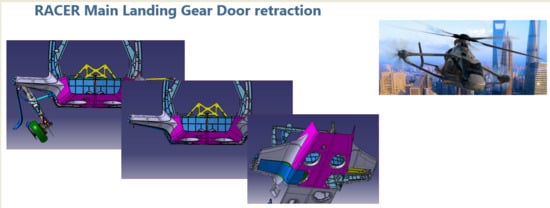
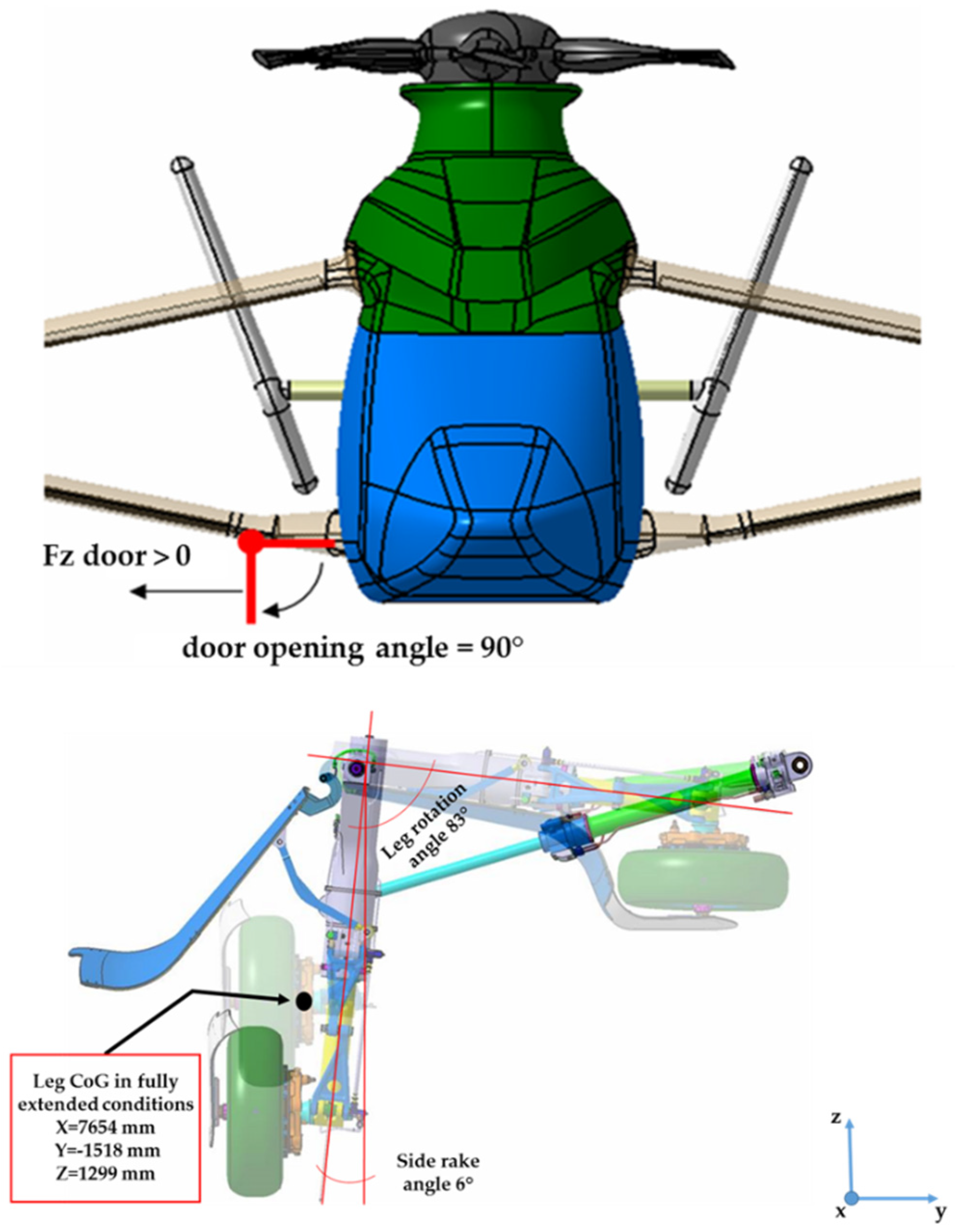
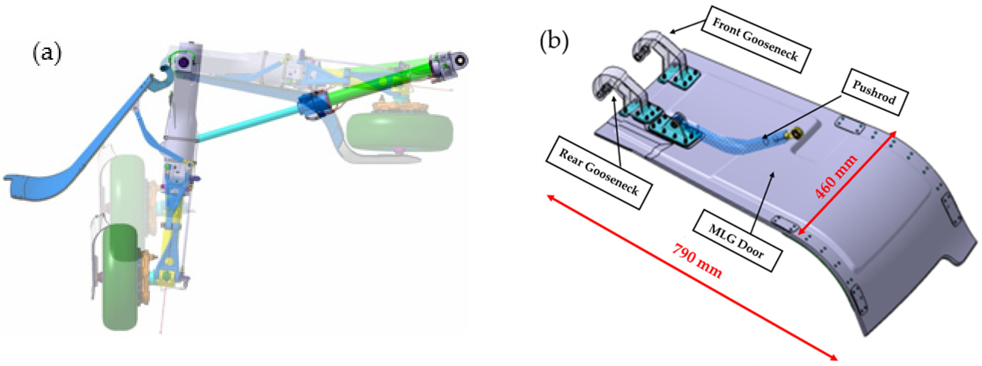
- Landing gear compartment doors for each MLG and for the NLG (Include the mechanism driven by the landing gear to open / close them).
1.2. Trap Doors General Requirements
- Stiffened door panel and hybrid metal-composite door panel design solutions were not compliant with the target weight, for this reason was rejected.
- Design solution based on a different kinematic configuration was discarded due to the absence of appropriate space in the landing gear bay.
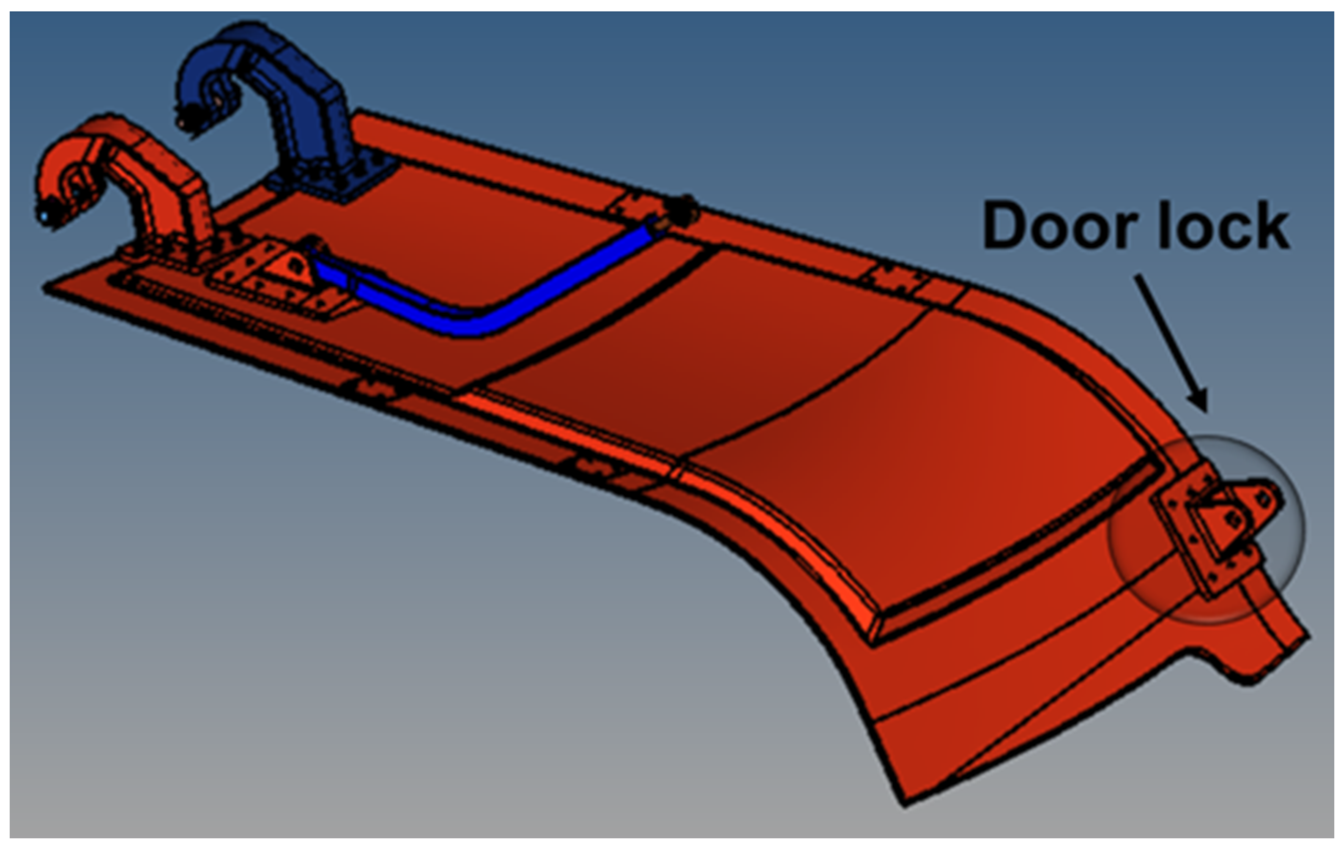
- Design solution considering a door lock mechanism at door free side of the panel door was discarded, since it did not permit the flushness requirement fulfillment Figure 3.
1.3. Main Landing Gear Trap Doors Outlines
2. Methods
2.1. Geometrical and Numerical FEM Model Description
- –
- A facing skin in composite material;
- –
- A backing skin in composite material;
- –
- An intermediate region filled by honeycomb material to properly space the two composite skins in the different parts of the structure.
2.2. Composite Panels
- –
- Region 1
- –
- Region 2
- –
- Region 3
- –
- The stiffness of the composite regions is represented in a very detailed way, namely the thicknesses are the same of the ones reported in the CAD model.
- –
- The congruency of the lower surfaces of the different regions is satisfied.
- –
- The honeycomb region is thicker than in the drawing. However, it does not significantly affect the stiffness of the structure, due to its low elastic properties with respect to the composite material ones.
2.3. Honeycomb
- –
- For the flat or nearly flat regions, a unique material reference system was considered (dark blue part in Figure 8); no approximation has been introduced in this case. This region is made by metallic honeycomb.
- –
- Considering that the curved regions are characterized by a constant curvature, due to the limited extension, it was defined by just one material reference system, positioned on the central area of the curved part, and locally tangent to the surface curvature (cyan part in Figure 8). This region is made by phenolic honeycomb.
2.3.1. Phenolic Core Mechanical Properties
2.3.2. Metallic Core Material Properties
2.4. Metallic Attachments
2.5. Bolt Connections
- –
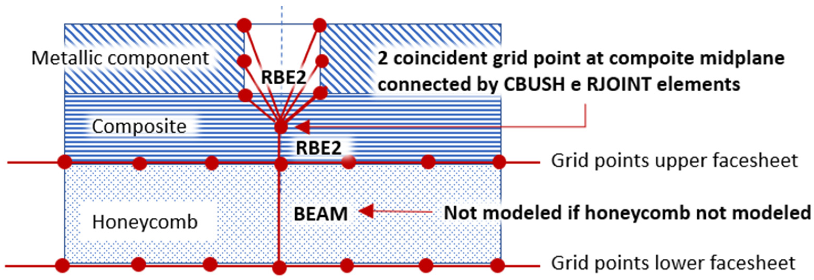
- A BEAM element, which diameter is the one of the bolts reported on the CAD model, connects the two points representing lower and upper facesheets (composite skins) of the honeycomb.
- –
- A RBE2 element connects a point (independent grid point) located at the midplane of the upper honeycomb facesheet (backing skin) to the grid points representing the lateral surface of the bolt accommodation in the metallic component.
- –
- A second point, coincident with the previous one, is create at upper honeycomb facesheet midplane location. It is part of a RBE2 element that connects it to the upper grid point of the BEAM element.
- –
- A Cartesian coordinate system is created as the analysis coordinate frame to the two coincident grid points. Its Z-direction is coincident with the axis of the bolt while one of the axes in the bolt section is oriented as the X of the coordinate system associated to the composite material.
- –
- A BUSH element connects the two coincident grid points in their common translational directions. The stiffnesses K1, K2 and K3 of the BUSH element are properly evaluated (using Huth Formula) according to the metallic and composite parts thicknesses and material properties. The analysis coordinate frame associated to the two coincident grid points has been used as the element coordinate system associated to the generic BUSH element.
- –
- Referring to the above coincident grid points, the rotational degrees of freedom associated to the directions of the common analysis coordinate system normal to the bolt axis, are rigidly linked by RJOINT element.
2.6. Spherical Joints Modeling
- –
- A RBE2 element connects the point at the center of the spherical joint to some points in the first component.
- –
- A second RBE2 element connects a new point at the center of the spherical joint to some points of the second component.
- –
- The two coincident grid points are connected in the translational degrees of freedom by using a RJOINT element.
- –
- Care must be taken in case the component is connected to the structure only by two spherical joints (the rod in the MLG door for example). In fact, in this case, the component is free to rotate around its axis. The rotation around the component axis is avoided by introducing this degree of freedom in one of the RJOINT used to describe the spherical joints.
- –
- In some cases, one of the two RBE2 element is substituted by a node of a flexible component (a BEAM representing a pin for example) at the spherical joint center.
2.7. Stoppers Modeling
2.8. Landing Gear Modelling
2.9. Carbon fiber reinforced plasticdescription
- –
- As already mentioned, the lower surface of the composite has been chosen to build the finite element model of the correspondent regions (OML surface for facing skin and internal surface for backing skin).
- –
- The offset to define the correct position of each laminate has been defined in the finite element entry (CQUAD4 or CTRIA3), not in the field Z0 of PCOMP entries. In this way, using MDLPRM, OFFDEF, LROFF (new parameters available in MSC Nastran), it is possible to take into account correctly the nonlinear effects of the offset.
Carbon Fiber Reinforced Plastic Mechanical Properties
2.10. Summary of the Final Model
2.11. Boundary Conditions and Constrains for MLG Door
- –
- Point A—Constrained in the degrees of freedom 1 and 3 (It is free to move along the line joining the points A and B).
- –
- Point B—Constrained in all the translational degrees of freedom.
- –
- Point C—Constrained in all the translational degrees of freedom.
- –
- Point D—Constrained in the degrees of freedom 1 and 2 (it is free to move along the line joining points C and D).
- –
- The Y axis of the coordinate system 194 corresponds to the line joining the points A and B, and therefore to the axis of the hinges of the goosenecks.
- –
- The Z axis of the coordinate system 407 corresponds to the line joining the points C and D.
3. Methodology to Determinate the Optimal Pre-Shape of the Main Landing Gear (MLG) Door
3.1. Preliminary Step: Determination of the Initial Clearances between MLG Door and Spherical Stoppers
- –
- phase 1—Actuator preload
- –
- phase 2—Aerodynamic load and ‘actuator preload’
Load Conditions
- –
- Clearance spherical stopper 1: 9.672 mm;
- –
- Clearance spherical stopper 2: 38.023 mm.
3.2. Step 1: Determination of the “Opposite Deformed Configuration”
- –
- The upper spherical hinge that connect it to the landing gear, must be relocated in its initial configuration to be congruent with the connecting part of the landing gear.
- –
- The location of the lower spherical hinge must be congruent with the deformed configuration of the pin of the pushrod attachment.
- –
- The grid points that define the RJOINT elements of the push-road attachments are no more coincident. One of the two grid points defining each of them must be moved to the location of the other.
- –
- The end grid points of the pin in the pushrod attachment must be aligned with the centre of the lower hinge of the pushrod.
- –
- The centres of the hinge of the goosenecks must be relocated at the position of the corresponding constrained grid points.
3.3. Step 2: Actuator Extension to Identify the Incipient Contact of One of the Two Stoppers
- –
- RJOINT in bolts modelling are defined by non-coincident grid points.
- –
- The deformed landing gear configuration must be replaced by the original one.
- –
- The pushrod deformed configuration must be replaced by the original one. Then, it must be repositioned in order to maintain the congruency with the adjacent components (landing gear and pushrod attachment). It determines also the repositioning of the pin of the hinge in the pushrod – pushrod attachment connection.
- –
- the door closure when actuator preload is applied.
- –
- the doors is kept closed when the aerodynamic external load are applied.
3.4. Step 3: Check of the Door Closure and OML Flushness
4. Results
5. Conclusions
Author Contributions
Funding
Acknowledgments
Conflicts of Interest
References
- Blacha, M.; Fink, A.; Eglin, P.; Cabrit, P. Clean Sky 2: Exploring new rotorcraft high speed configurations. In Proceedings of the 43rd European Rotorcraft Forum, Milan, Italy, 12–15 September 2017. [Google Scholar]
- Thiemeier, J.; Öhrle, C.; Frey, F.; Keßler, M.; Krämer, E. Aerodynamics and flight mechanics analysis of Airbus Helicopters’ compound helicopter RACER in hover under crosswind conditions. CEAS Aeronaut. J. 2019, 11, 49–66. [Google Scholar] [CrossRef] [Green Version]
- Paletta, N.; Belardo, M.; Di Palma, L. An Automatic Procedure for the Landing Gear Conceptual Design of a Light Unmanned Aircraft. SAE Tech. Pap. Ser. 2013. [Google Scholar] [CrossRef]
- Paletta, N.; Belardo, M.; Di Palma, L. Non-Linear Dynamic Loads Due to the Landing Impact of a Joined-Wing UAV. SAE Tech. Pap. Ser. 2011. [Google Scholar] [CrossRef]
- Di Palma, L.; Di Caprio, F.; Chiariello, A.; Ignarra, M.; Russo, S.; Riccio, A.; de Luca, A.; Caputo, F. Vertical Drop Test of Composite Fuselage Section of a Regional Aircraft. AIAA J. 2020, 58, 1–5. [Google Scholar] [CrossRef]
- Belardo, M.; Paletta, N.; Di Palma, L.; Pecora, M. Structural and Aeroelastic Design of a Joined-Wing UAV. J. Aerosp. Eng. 2014, 27, 93–111. [Google Scholar] [CrossRef]
- Mark, A.; Gambling, M. Efficient Shape Optimization of an Aircraft Landing Gear Door Locking Mechanism by Coupling Abaqus to GENESIS. In Proceedings of the 2009 SIMULIA Customer Conference, London, UK, 13 May 2009; Available online: https://www.grm-consulting.co.uk/images/pdf/papers/05_Abaqus_Coupling (accessed on 12 May 2020).
- Viúdez-Moreiras, D.; Martín, M.; Abarca, R.; Andrés, E.; Ponsín, J.; Monge, F. Surrogate modeling for the main landing gear doors of an airbus passenger aircraft. Aerosp. Sci. Technol. 2017, 68, 135–148. [Google Scholar] [CrossRef]
- Paletta, N.; Belardo, M.; di Palma, L. Evaluation of wing loads during the flight drop test of the italian unmanned space vehicle. In Proceedings of the 5th International Operational Modal Analysis Conference, IOMAC, Guimaraes, Portugal, 13–15 May 2013; pp. 1–12, EID: 2-s2.0-. [Google Scholar]





| Honeycomb Designation | Nominal Density (Kg/m3) | Compressive Modulus (MPa) | Plate Shear Modulus (MPa) | ||
|---|---|---|---|---|---|
| USA | EU | Stabilized | L Direction | W Direction | |
| HRH-10-3/16-3.0 | A1-5-48 | 48 | 137 | 44 | 23 |
| Honeycomb Designation | Nominal Density (Kg/m3) | Compressive Modulus (MPa) | Beam Shear Modulus (MPa) | |
|---|---|---|---|---|
| 1/8 - 2 - .006 - STD | 319 | Stabilized | L Direction | W Direction |
| 6687 | 3033 | 689 | ||
| Component | Material | Element Type | Component View |
|---|---|---|---|
| Gooseneck 1 | Aluminum | TETRA |  |
| Gooseneck 2 | Steel | TETRA |  |
| Pushrod Attachment | Aluminum | HEXA |  |
| Pushrod | Steel | TETRA |  |
| Number of Plies | Orientation | Single Ply Thickness (mm) | Laminate Thickness (mm) |
|---|---|---|---|
| 28 | (45°/0°/45°/0°/45°/0°/45°/45°/0°/45°/0°/45°/0°/45°)S | 0.31877 | 8.925 |
| 16 | (45°/0°45°/0°/0°/45°/0°/45°)S | 0.31877 | 5.1 |
| 14 | (45°/0°/45°/0°/45°/0°/45°)S | 0.31877 | 4.463 |
| 8 | (45°/0°/45°/0°)S | 0.31877 | 2.55 |
| Properties | Direction | Modulus | RTD Value (MPa) |
|---|---|---|---|
| Tension | 0 | E11 | 59777 |
| Compression | 0 | −E11 | 55916 |
| Tension | 90 | E22 | 58053 |
| Compression | 90 | −E22 | 55020 |
| Shear | - | G12 | 3930 |
| Poisson ratio | - | ν12 | 0,056 |
| Density (Kg/m3) | Cured ply thickness (mm) | ||
| 1520 | 0.31877 |
| Entity Type | Number of Entities |
|---|---|
| Grid nodes | 66632 |
| BAR | 49 |
| BEAM | 22 |
| BUSH | 26 |
| HEXA | 15259 |
| PENTA | 230 |
| QUAD4 | 12415 |
| TETRA | 24021 |
| TRIA3 | 106 |
| Case | V (kt) | Alpha (°) | Beta (°) |
|---|---|---|---|
| Beta - diagram | 80 | 0 | 87 |
| 125 | 0 | 53 | |
| 170 | 0 | -32 | |
| 255 | 0 | 6 | |
| Alpha - diagram | 100 | 12 | 0 |
| 255 | -2 | 0 |
| Aero-Load | Max. Negative Distance (mm) | Max. Positive Distance (mm) |
|---|---|---|
| LC-1 | 1.29 | 1.28 |
| LC-2 | 1.32 | 1.25 |
| LC-3 | 1.36 | 1.19 |
| LC-4 | 2.02 | 1.05 |
| LC-5 | 3.00 | 1.15 |
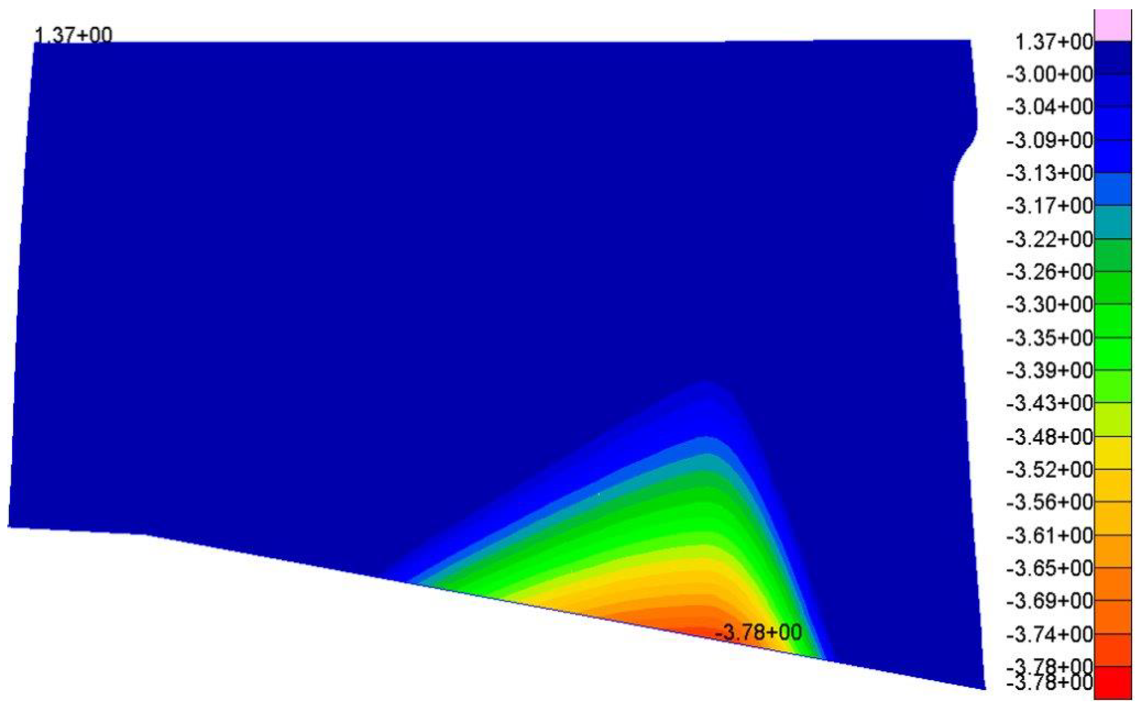
| LC-6 | 3.78 | 1.37 |
© 2020 by the authors. Licensee MDPI, Basel, Switzerland. This article is an open access article distributed under the terms and conditions of the Creative Commons Attribution (CC BY) license (http://creativecommons.org/licenses/by/4.0/).
Share and Cite
Chiariello, A.; Orlando, S.; Vitale, P.; Linari, M.; Longobardi, R.; Di Palma, L. Development of a Morphing Landing Gear Composite Door for High Speed Compound Rotorcraft. Aerospace 2020, 7, 88. https://doi.org/10.3390/aerospace7070088
Chiariello A, Orlando S, Vitale P, Linari M, Longobardi R, Di Palma L. Development of a Morphing Landing Gear Composite Door for High Speed Compound Rotorcraft. Aerospace. 2020; 7(7):88. https://doi.org/10.3390/aerospace7070088
Chicago/Turabian StyleChiariello, Antonio, Salvatore Orlando, Pasquale Vitale, Mauro Linari, Raffaele Longobardi, and Luigi Di Palma. 2020. "Development of a Morphing Landing Gear Composite Door for High Speed Compound Rotorcraft" Aerospace 7, no. 7: 88. https://doi.org/10.3390/aerospace7070088
APA StyleChiariello, A., Orlando, S., Vitale, P., Linari, M., Longobardi, R., & Di Palma, L. (2020). Development of a Morphing Landing Gear Composite Door for High Speed Compound Rotorcraft. Aerospace, 7(7), 88. https://doi.org/10.3390/aerospace7070088


