The simulation models for this paper are generated using the design process cpacs-MONA [
22]. At the beginning of this paragraph, the general MONA concept is summarized followed by a fairly detailed description of the automatized cpacs-MONA process. An explicit view of the parametric modeling for the engine-wing integration is presented at the end of this paragraph.
2.2.2. The Automatized cpacs-MONA Process
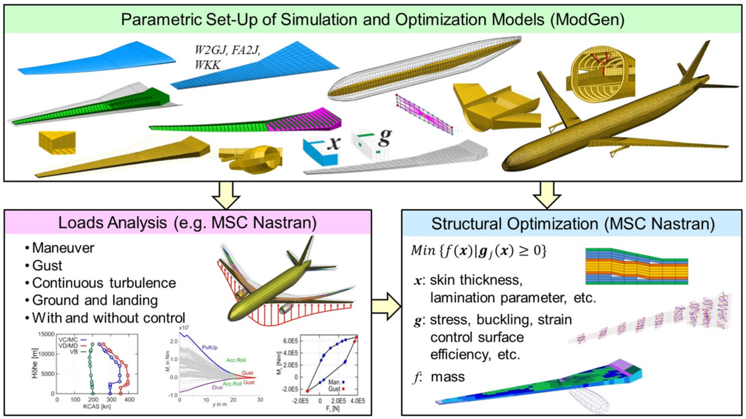
The automatized tool-like process cpacs-MONA has been derived from the basic MONA process to perform aeroelastic structural design for different aircraft configurations. cpacs-MONA is integrated in DLR wide established design processes using a Common Parametric Aircraft Configuration Schema (CPACS) dataset for data exchange. cpacs-MONA can be used as a stand-alone tool (like for this paper) or as part of various aircraft design processes like high-fidelity MDO chains [
26,
27,
28]. cpacs-MONA is built modular and is written in Python code. It extracts the information about the aircraft from a CPACS dataset. CPACS stands for Common Parametric Aircraft Configuration Schema and is written in XML format [
29]. CPACS describes a wide range of the aircraft characteristics like the outer geometry (profiles and segments), the global aircraft parameters, the topology of the inner structure, the engine outer shape, and much else. Besides, the aircraft information also processes information like aerodynamic data, aircraft loads, or a more or less detailed mass distribution for each component that can be stored in the CPACS dataset. Moreover, tool parameters are stored in the dataset. cpacs-MONA automatically reads out the information about the wing planform, the wing topology like ribs, spars, and stringer positions, and initial component thicknesses together with the engine, pylon, and landing gear positions and dimensions. It also uses information about aircraft masses like design, primary and secondary masses plus the dimensions of the control surfaces, and the borders of the fuel tanks. With this information, cpacs-MONA creates suitable input-files for the involved tools. For ModGen, each component (wing, horizontal and vertical tail, fuselage) is built separately and executed in parallel. Furthermore, the MSC Nastran simulations like the static aeroelastic trim analysis [
30] (solution 144) and the structural optimization analysis [
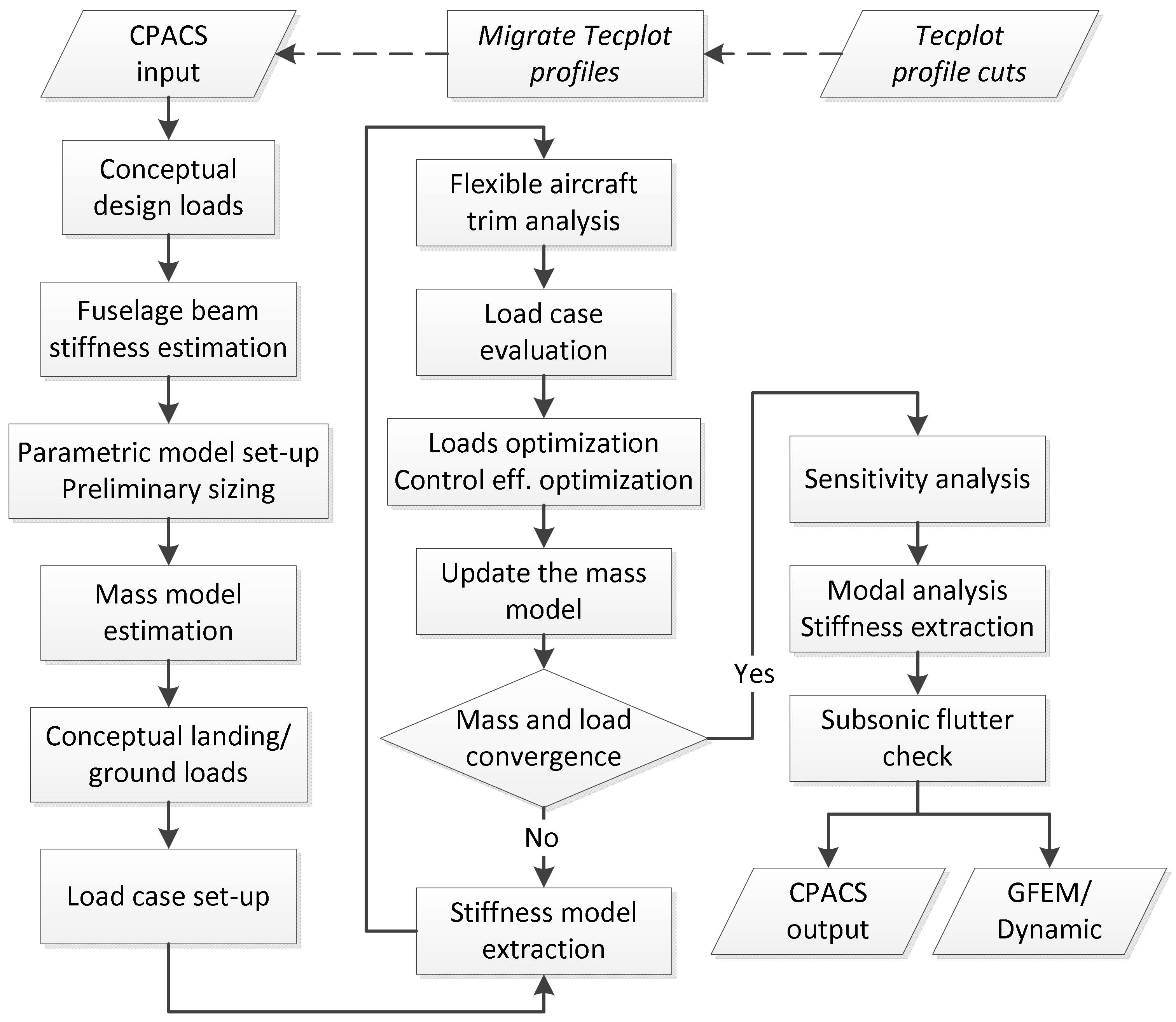
31] (solution 200) can be executed in parallel. Besides the already mentioned tools like ModGen and MSC Nastran, cpacs-MONA combines many tools written in different programming languages forming an automated process flow as shown in
Figure 5.
The process starts with an estimation of preliminary loads based on conceptual design methods [
32] followed by an estimation of a generic beam model representing the fuselage stiffness. The conceptual loads are used for a preliminary cross-section sizing (PCS) within ModGen [
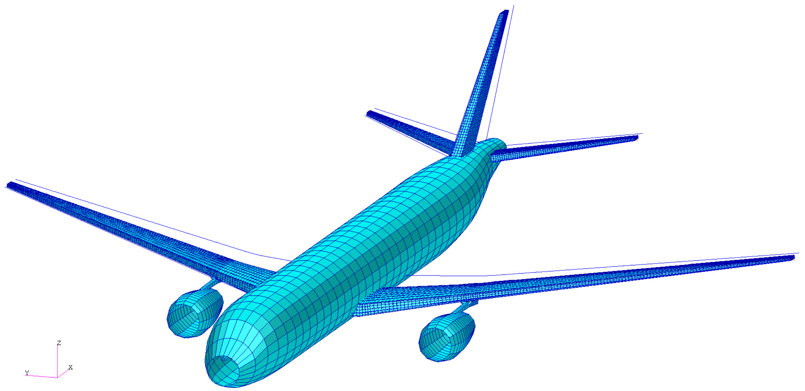
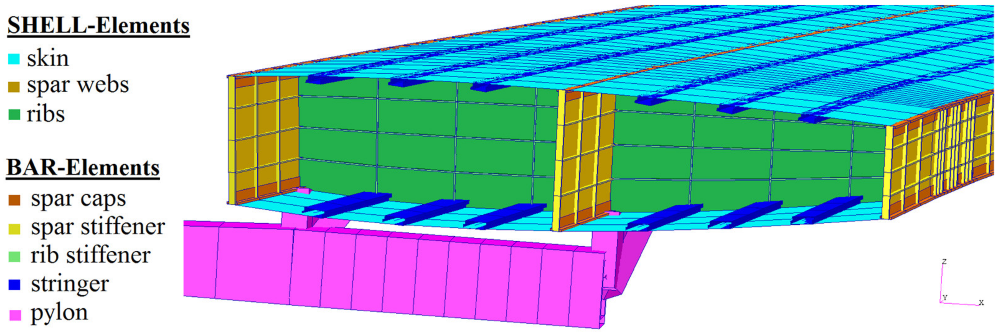
33]. Due to the PCS, a more realistic wing representative with respect to the shell thickness distribution and bar properties is provided. As shown in
Figure 6, the wing ribs, spars, and skins are modeled with shell elements. The other wing component structures like the spar caps, the reinforcement structure, or the stringers are modeled with bar or beam elements. The pylon is modeled with beam elements and its structural properties are also defined parametrically as presented in more detail in
Section 2.2.3.
For a conclusively substantiated aeroelastic analysis, reasonable mass models have to be set-up. Therefore, a mass model tool reads out the mass-breakdown for each component and creates a model with distributed mass and inertia entities in line with the given geometrical space of the individual component. The fuel tank volume is calculated according to the geometrical borders (ribs, spars) as defined in CPACS. The masses of the engine and landing gear are extracted from the CPACS dataset and converted into CONM2 elements. The resulting operating mass empty (OME) together with defined combinations of fuel and payload/passenger masses form the design masses of the aircraft. The generated mass cases have an internal ID. This ID together with the percentage indication of the payload and fuel compositions used within this work are listed in
Table 3.
The mass model set-up is followed by a conceptual ground and landing loads estimation. Then, the trim conditions (load factor, roll rate, pitching velocity, etc.) for the load cases are set-up according to CS-25.335 [
34]. For this paper, 730 load cases containing symmetrical pull-up and push-down maneuvers, yawing and rolling maneuvers paired with quasi-stationary gust encounters according to the Pratt formulation are generated. To reduce the complexity of the GFEM/Dynamic for the extensive loads analysis, the stiffness of the structural model is condensed to the loads reference axis (LRA) points. This condensed model is set-up by ModGen using RBE3 interpolation elements with a so-called UM option [
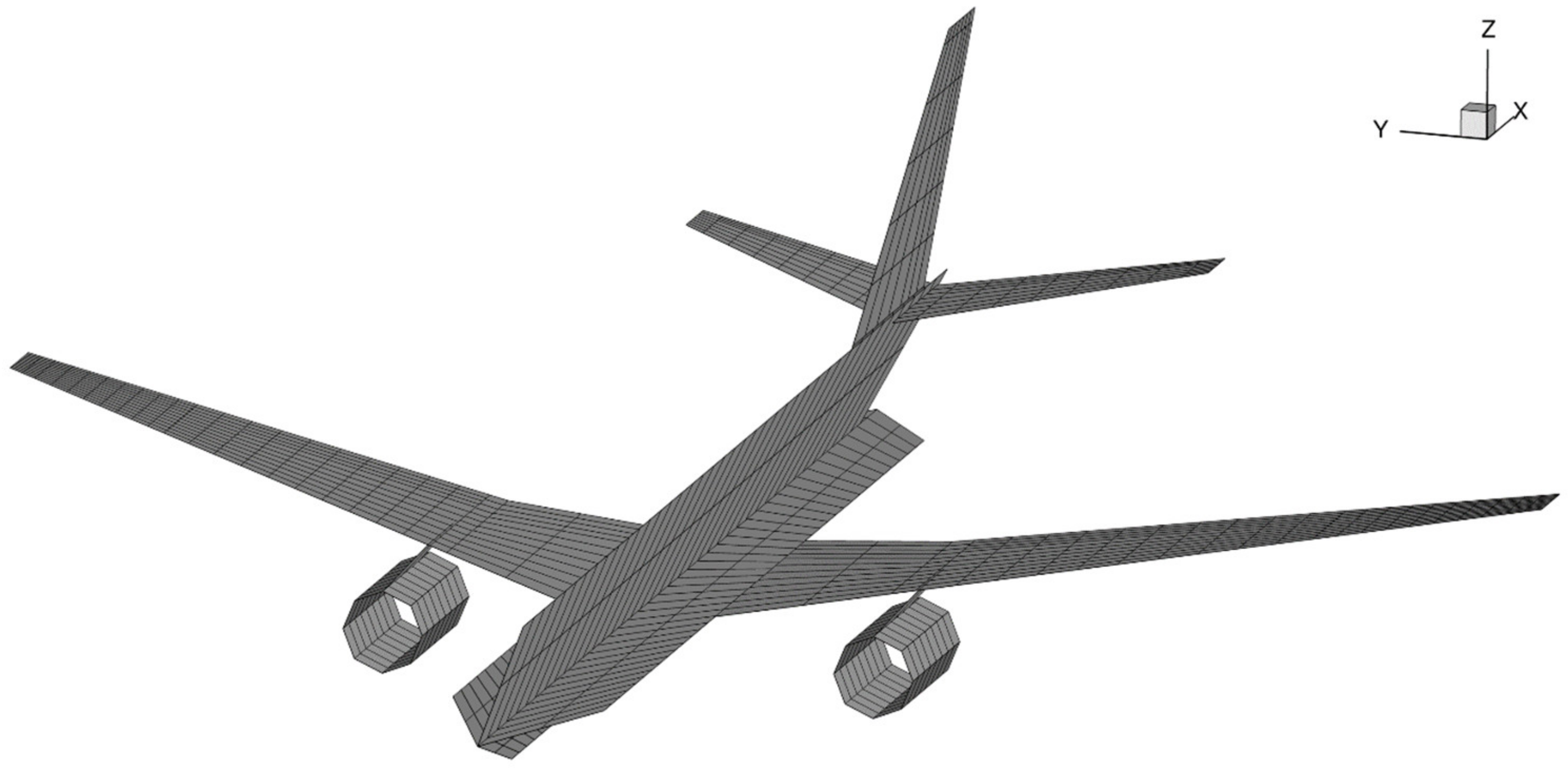
35]. This model has the same dynamic characteristic (mass and stiffness) as the full GFEM/Dynamic but much less degrees of freedom. The full model of the DLR-D250 consists of about 35.000 FE-nodes and roughly 42.000 finite elements. The condensed GFEM/Dynamic consists solely of 478 FE-nodes forming the stiffness matrix and the mass model with concentrated mass entities (CONM2-cards) and 352 finite elements. RBE2-elements and corresponding nodes are used for the aeroelastic coupling of the structural and the aerodynamic model. Spline elements transfer the forces and motions between the two models. The condensation reduces the computational effort for the extensive aeroelastic analysis of the flexible aircraft.
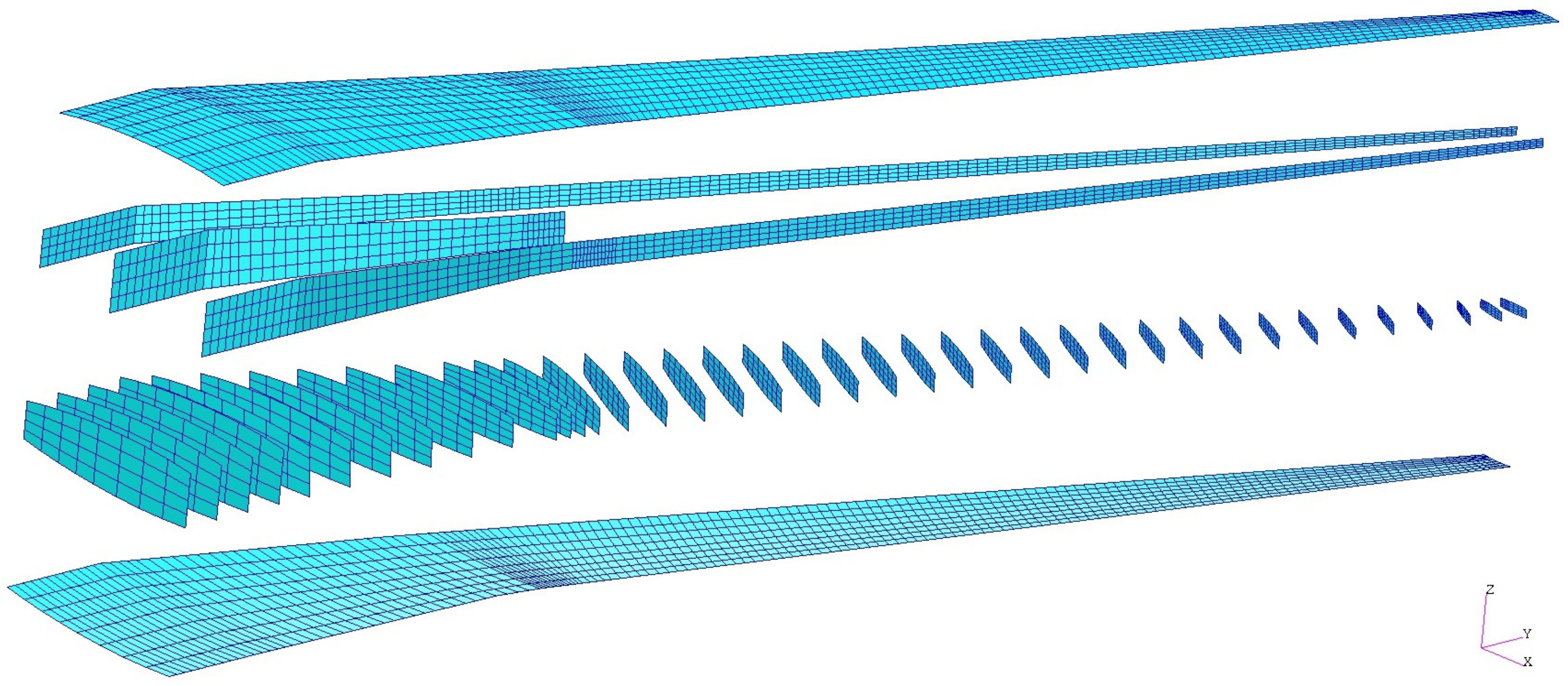
The automatically generated aerodynamic model is shown in
Figure 7. This model consists of macro panel elements for the vortex and doublet lattice method (VLM [
36] and DLM [
37]). Within the elastic trim analysis, the macro panels of the wing-like structures are geometrically corrected to account for the camber and twist effects of the wing. Aerodynamic corrections to account for compressibility effects have not been considered within this publication. The control surfaces like elevator, rudder, and aileron are also defined within the aerodynamic model according to their definition within the CPACS dataset. The structural model does not contain control surfaces.
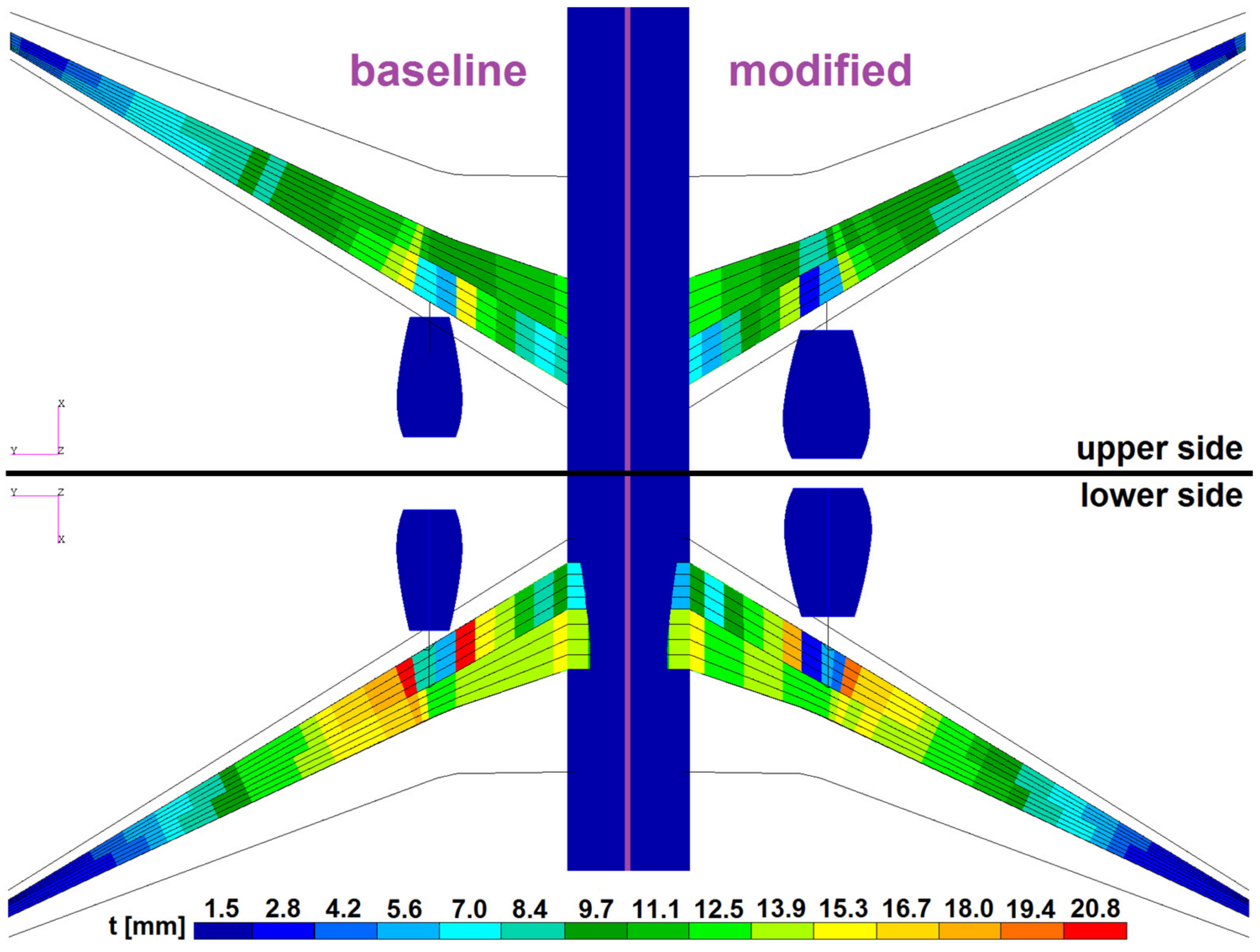
The load cases with the maximum and minimum cutting moments for torque, shear, and bending are selected for each wing-like component. The forces and moments of these load cases are extracted and used for the structural optimization of the wing-like components. The objective function for the structural optimization is to minimize the wing-box mass under consideration of aeroelastic constraints like control surface efficiency (for the main wing only) or allowable stress values per shell element. The stresses are based on yielding, ultimate strength, and local buckling. As a design variable, the thickness of the shell elements from the load-carrying wing structure can be adjusted to fulfill the objective function. The design variables are combined to design regions to reduce the size of the optimization task. The design regions of the wing-box are on the one hand the partial skin surfaces, surrounded by spars and ribs, and the partial rib and spar surfaces due to their intersections among each other. Since the wing-box of the DLR-D250 main wing consists of 39 ribs and three spars, the optimization model consequently exists of 78 design variables for the ribs, 76 for each skin cover, and altogether 88 for the spars. In total, 318 design variables are optimized to minimize the wing-box mass of the main wing. The dimensions of the reinforcement bar elements (sized within the PCS) are not part of the optimization task. The analysis of loads and structural optimization are iteratively coupled. The mass and the stiffness of the simulation models are updated at each iteration step until the mass and loads of the complete aircraft configuration are converged. For more details on each of the single process steps, see Reference [
22].
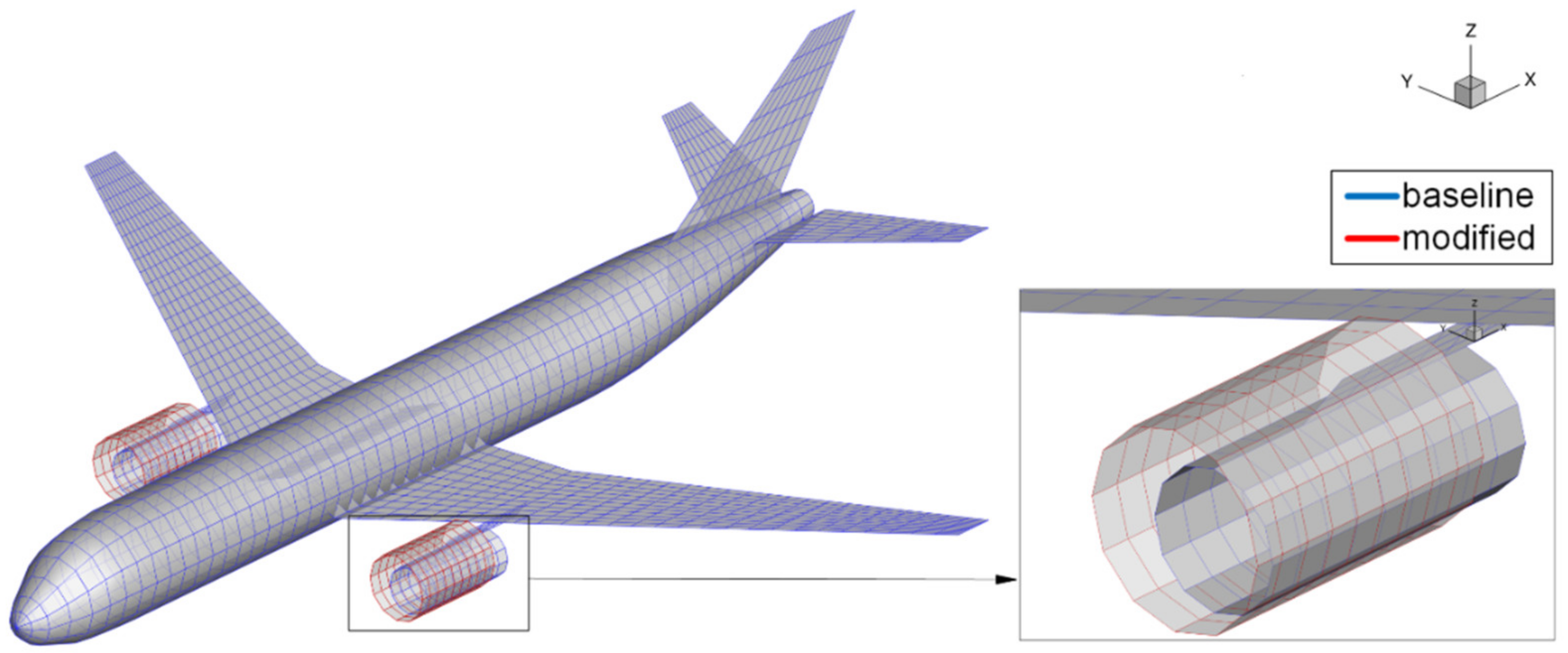
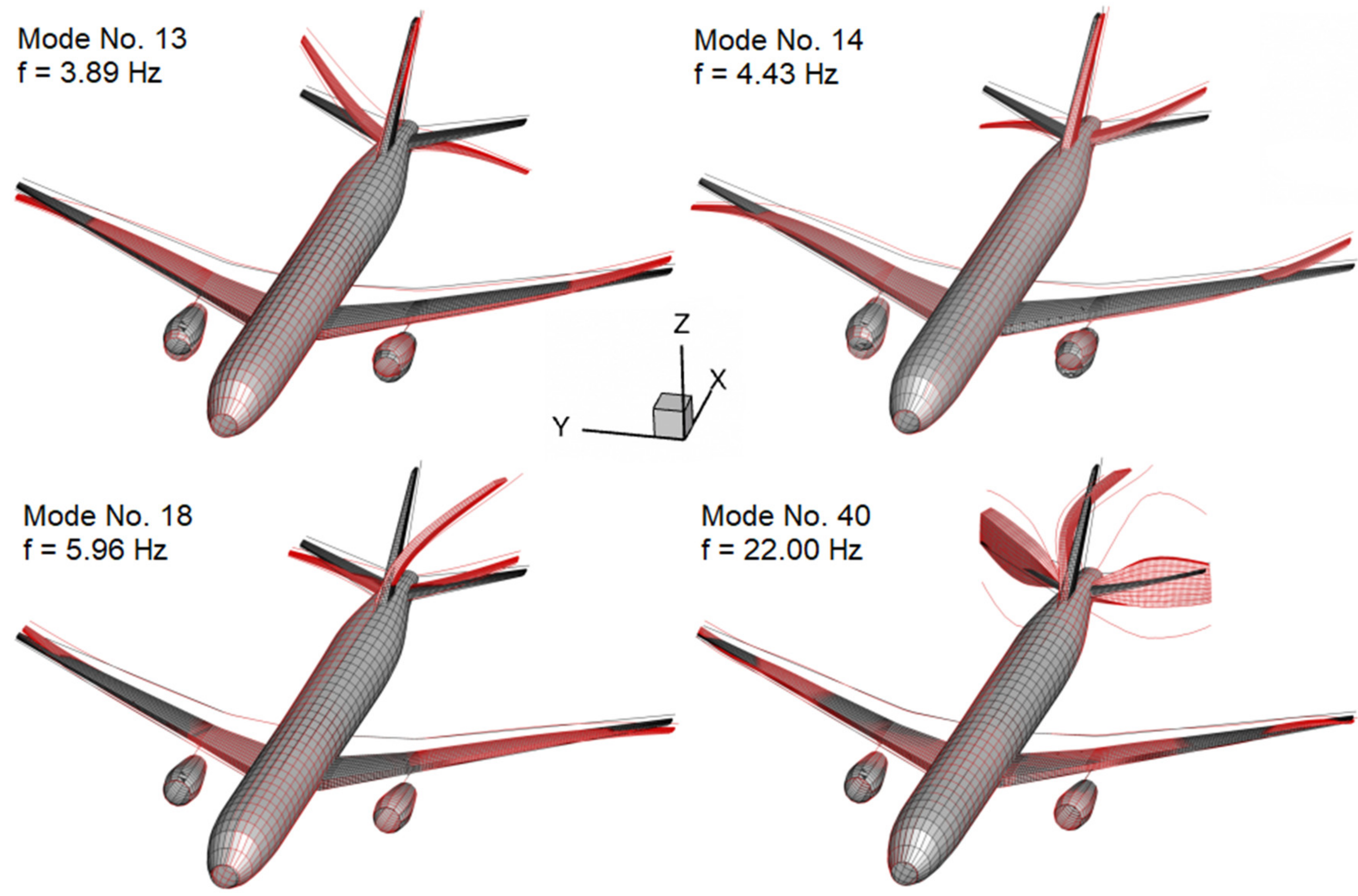
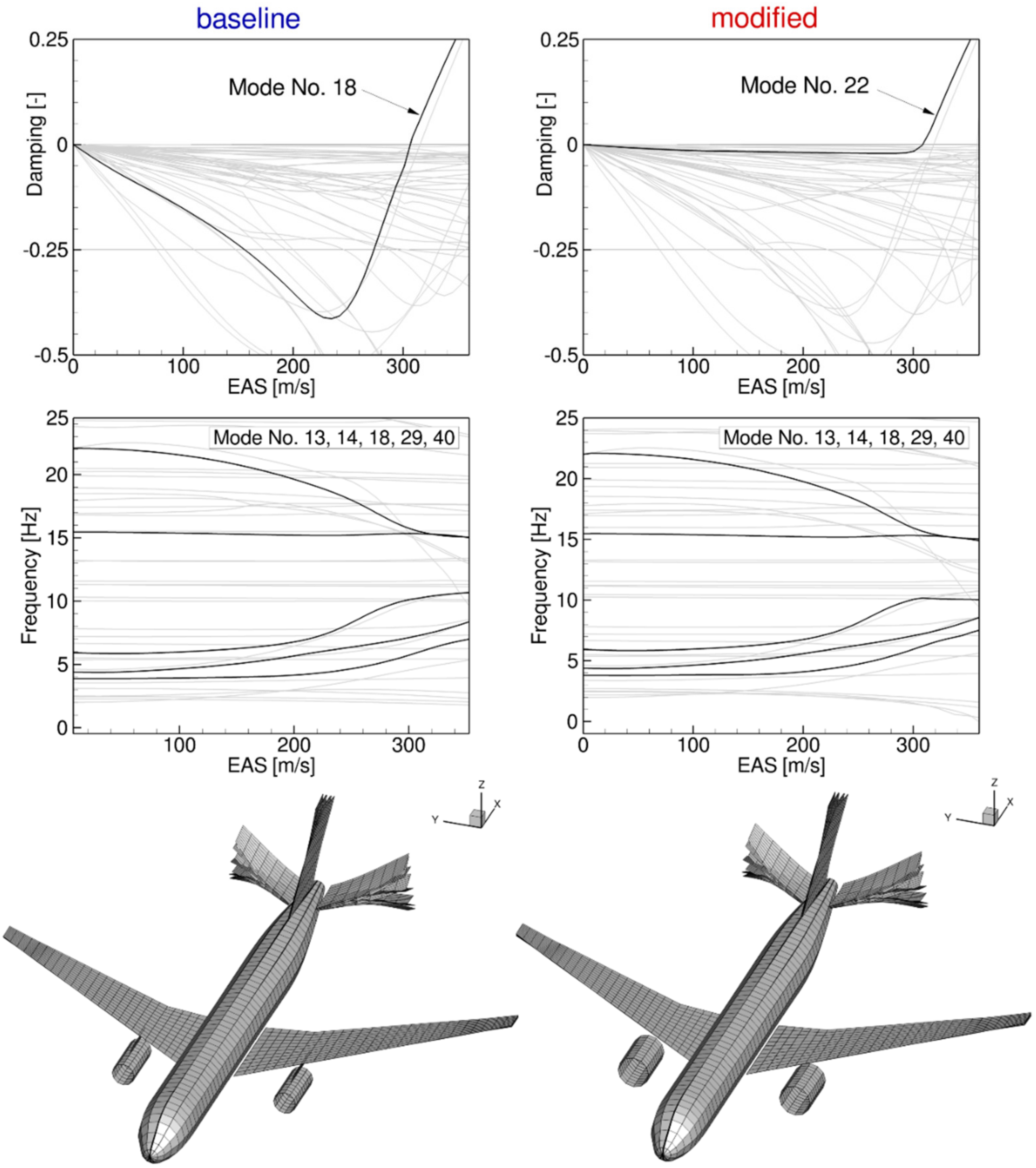
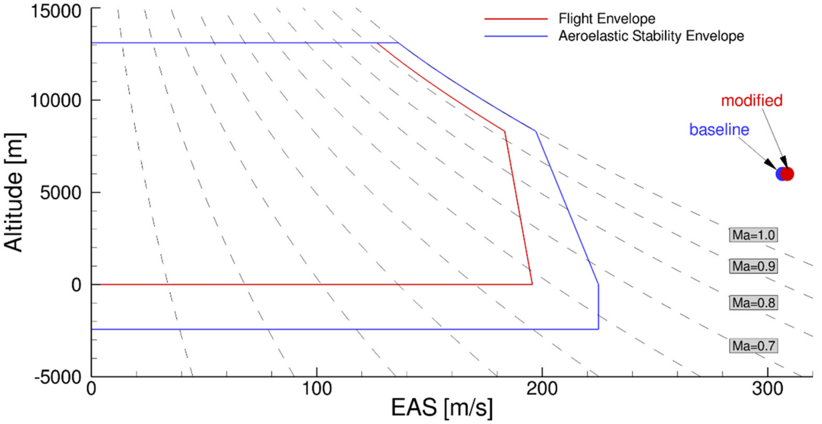
This degree of process automatization shows that cpacs-MONA does not set-up the simulation models for the two investigated configurations by changing the mass and the outer geometry of the engine. To a greater degree, it optimizes the load-carrying wing structure of each aircraft configuration in an iterative loads and structural optimization loop to best bear the loads coming from the different engine-wing integrations. The resulting structural GFEM/Dynamic models of the two different configurations are afterward used for a manual flutter analysis to investigate the influence of the modified engine on the dynamic aeroelastic behavior of the aircraft.
2.2.3. Parameterized Engine-Wing Integration
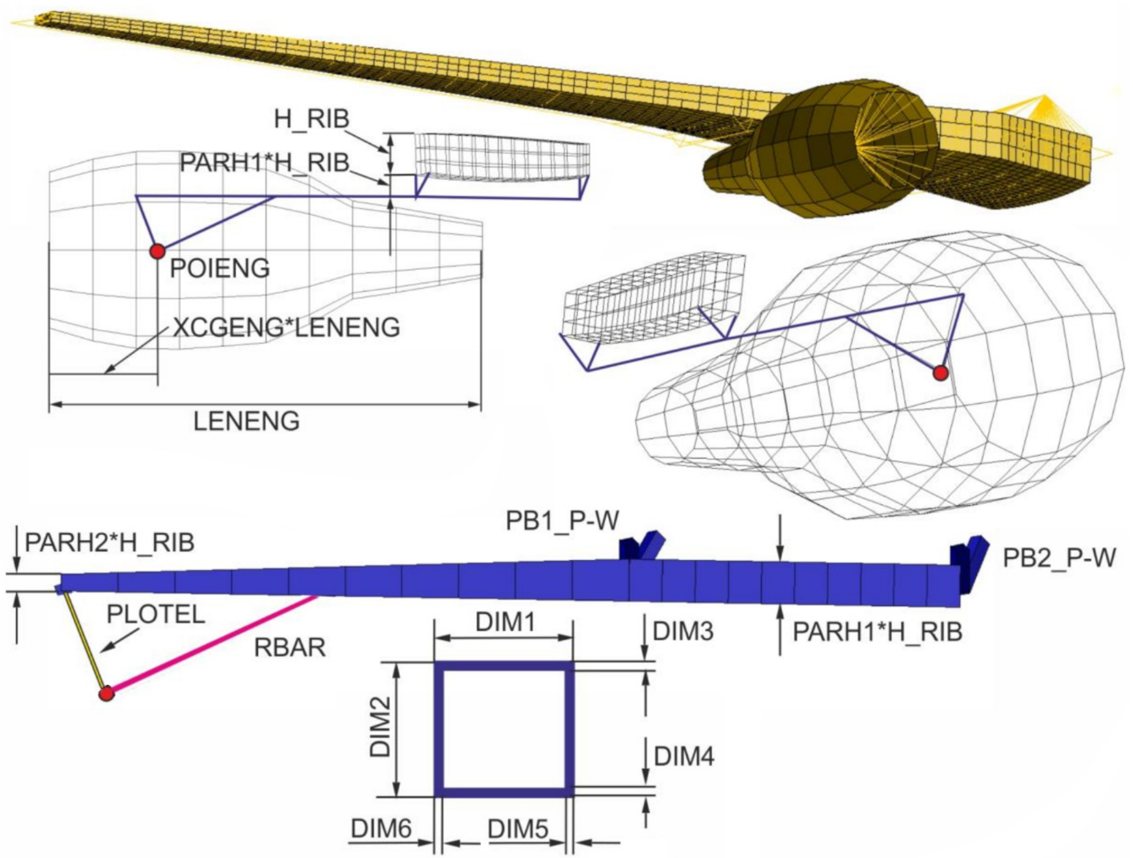
The structural model of the pylon as engine-wing integration unit and the engine’s nacelle are modeled with ModGen. cpacs-MONA reads out the necessary parameters and creates corresponding ModGen input cards. For a wing-mounted pylon-engine model, the ModGen input card is called GEPYLO2. ModGen is also capable of building a parameterized fuselage-mounted engine-pylon model or a turboprop engine frame. The main parameters of the GEPYLO2 card together with a visualization of the structural model of the pylon are shown in
Figure 8.
The maximum outer diameter of the engine nacelle and its location are extracted from the CPACS dataset and written into the ModGen input card. For the location, ModGen needs the center of gravity (CG) of the engine (POIENG) and the percentage position of the CG (XCGENG) according to the engine length (LENENG). With these three parameters, the position of the engine is adjusted in the global coordinate system. ModGen directly takes the maximum diameter (MAXDIA) and the length (LENENG) as input parameters. The XCGENG parameter has to be calculated within cpacs-MONA with the known CG position extracted from the CPACS mass-breakdown branch, the nacelle entrance point, and its length.
After the engine is positioned, the structural model of the pylon is set-up. The parameters for the pylon dimensions are not stored within the CPACS dataset. They have to be defined by the user before cpacs-MONA is executed. The pylon structure is built with PBEAML elements according to the Nastran BOX1-type definition. The parameters DIM3 to DIM6 define the wall-thickness of the pylon structure. The width (DIM1) and the height (DIM2) of the pylon are calculated as a function of the parameters PARH1, PARH2, the height of the attachment-rib (H_RIB), and the actual x-position on the pylon (see
Figure 8). The preset values for the aforementioned pylon parameters for the baseline and the modified configuration are listed in
Table 4.
The pylon can be attached to the wing-box at a defined number of rib stations (NBSRBS). Two ribs are used for the DLR-D250. ModGen automatically estimates the ribs for the attachment according to the y-coordinate of the engine. In case the wing box is equipped with a mid-spar, ModGen attaches the pylon to the front- and mid-spar, otherwise to the front- and rear-spar. The attachment structure from the pylon to the wing (PB1_P-W and PB2_P-W) is modeled with Nastran PBARL elements with the BAR-type. Both bar elements for the pylon-wing attachment have the same quadratic cross-section within cpacs-MONA. The attachment structure from the engine mass point to the pylon is modeled with rigid RBAR elements to account for the high stiffness of the core engine.
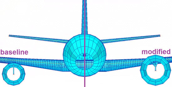
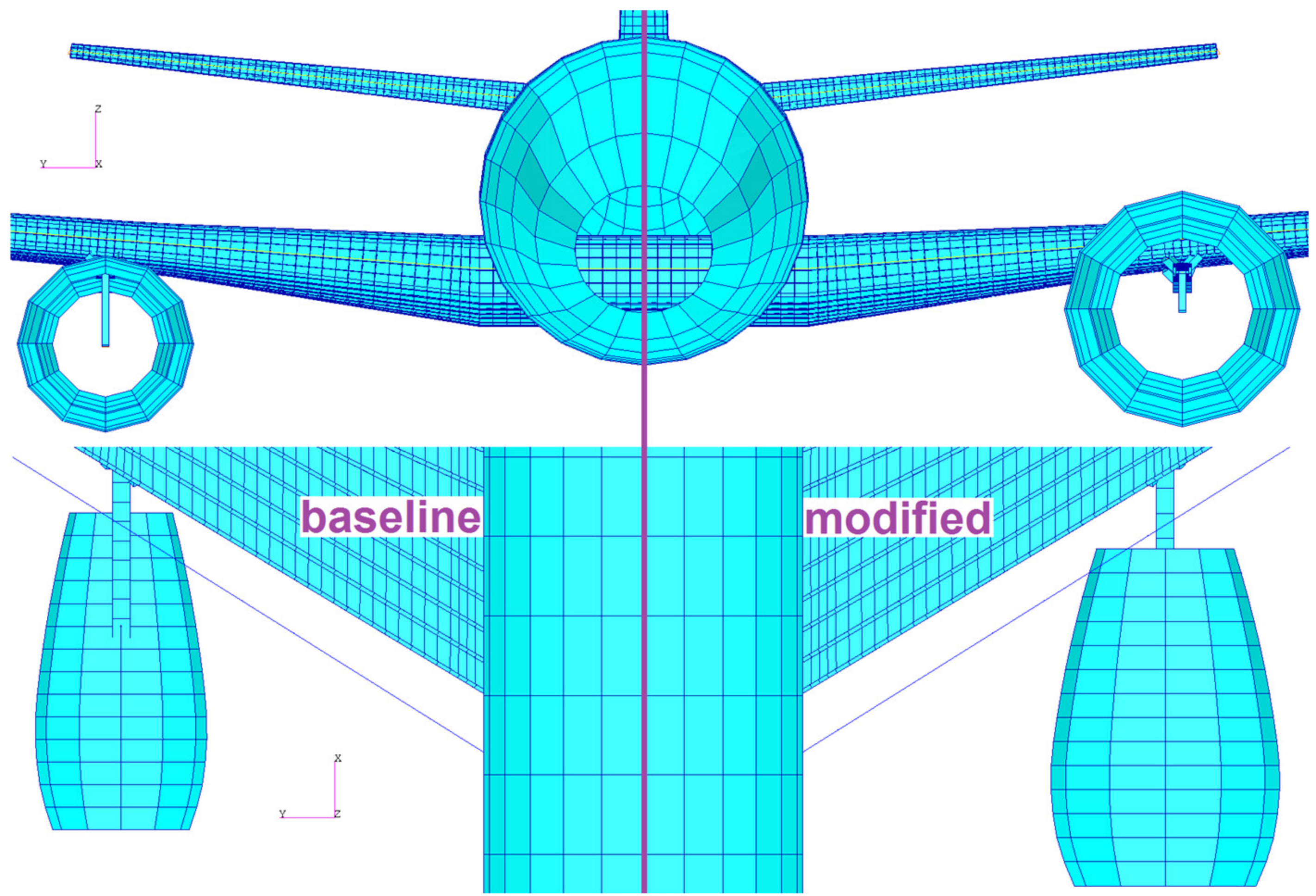
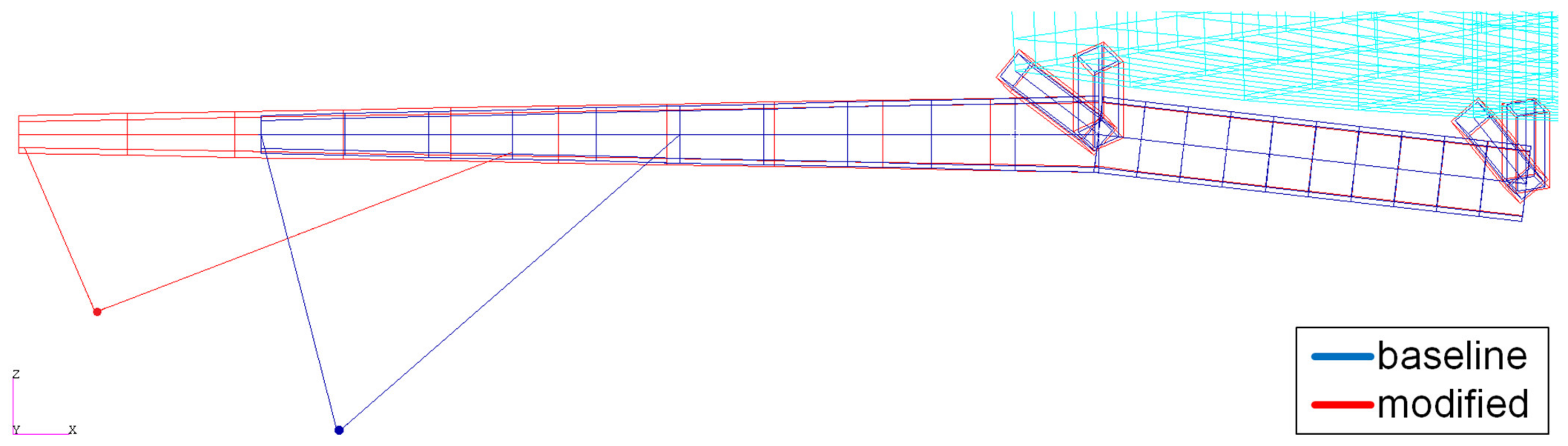
Figure 9 visualizes the resulting pylon structure for both investigated variants.


