Model Updating and Aeroelastic Correlation of a Scaled Wind Tunnel Model for Active Flutter Suppression Test
Abstract
:1. Introduction
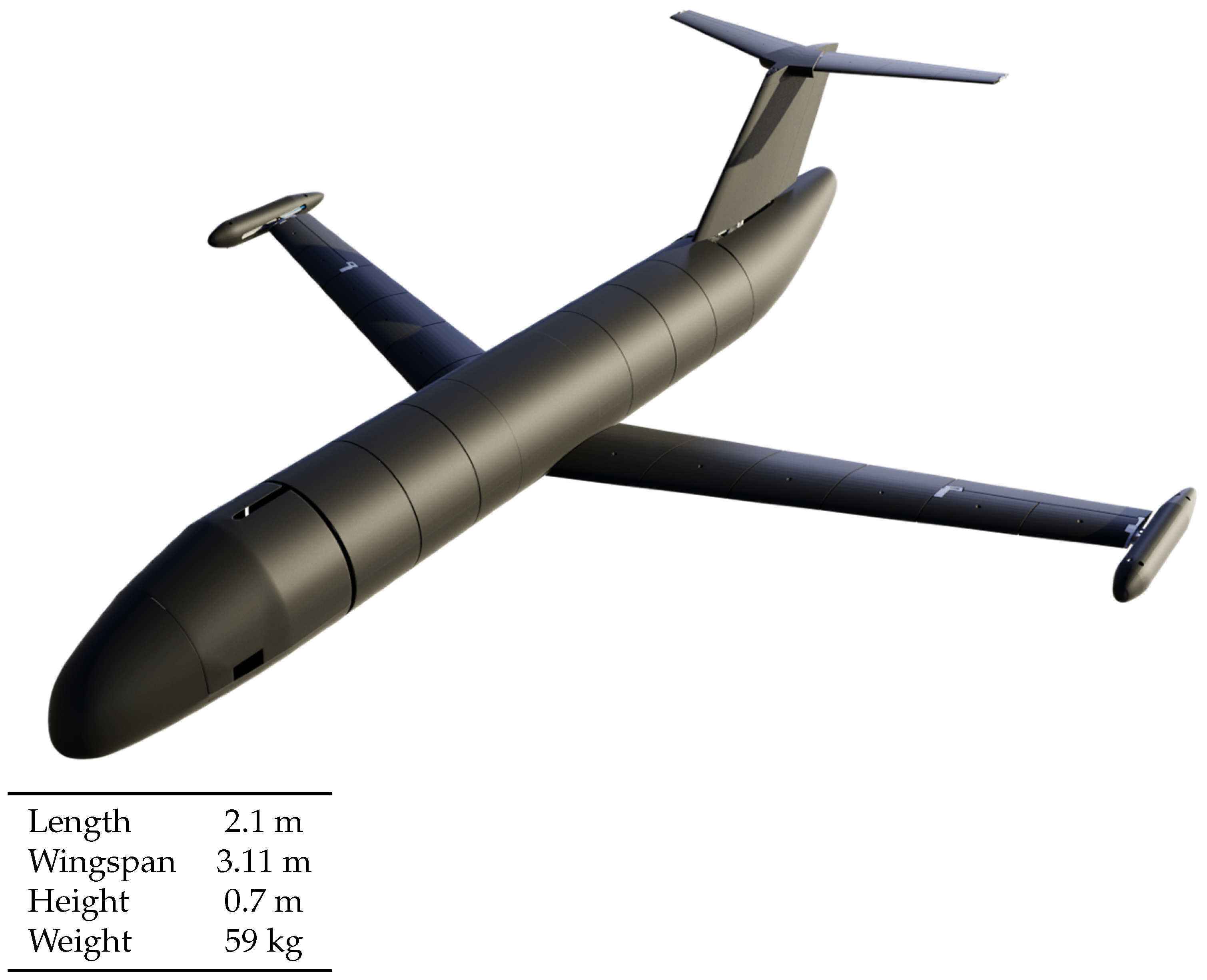
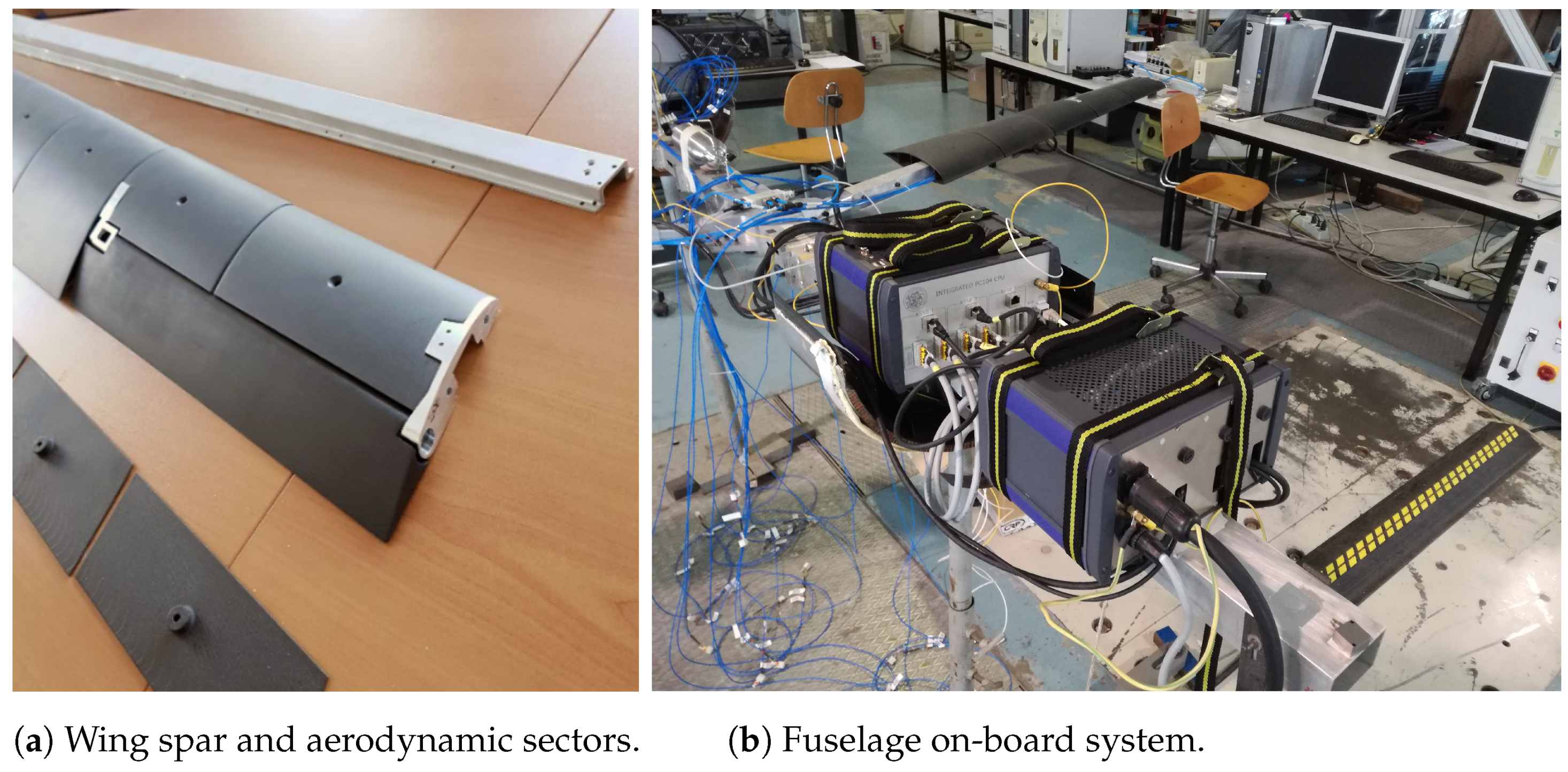
2. The X–Dia Wind Tunnel Model
3. Ground Vibration Test (GVT)
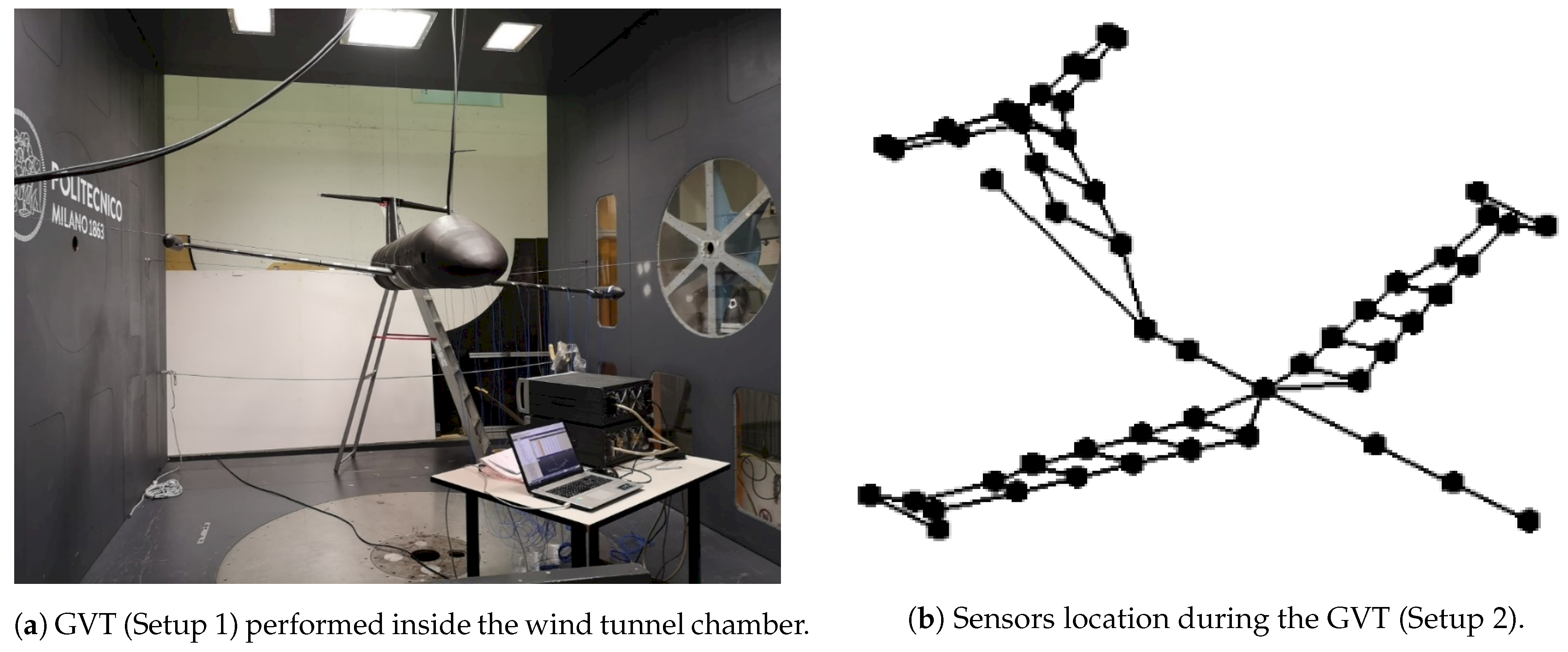
- Setup 1:
- all the lifting surfaces—i.e., wings, horizontal planes, and vertical tail—have been measured in the out-of-plane direction. A roving hammer impact test has been carried out, limiting the mass loading effect due to the mass of the accelerometers. Five fixed accelerometers have been installed upon the structure and used as references, while the other points have been used for excitation and computed with 10 averages, for a total of 46 measurements.
- Setup 2:
- the left wing has been instrumented with 28 fixed accelerometers that are equally distributed to measure in both in and out-of-plane direction. The excitation has been introduced by the hammer impact. This setup has been realized mainly to investigate deeply specific aspects, such as the dynamic behavior of the pod.
- 1.
- Safety On: the aircraft with the mass of both anti-flutter devices fully forward.
- 2.
- Safety Off: the aircraft with the mass of both anti-flutter devices fully backward.
- As expected, the different position of the tip masses has a limited impact on the frequencies and damping.
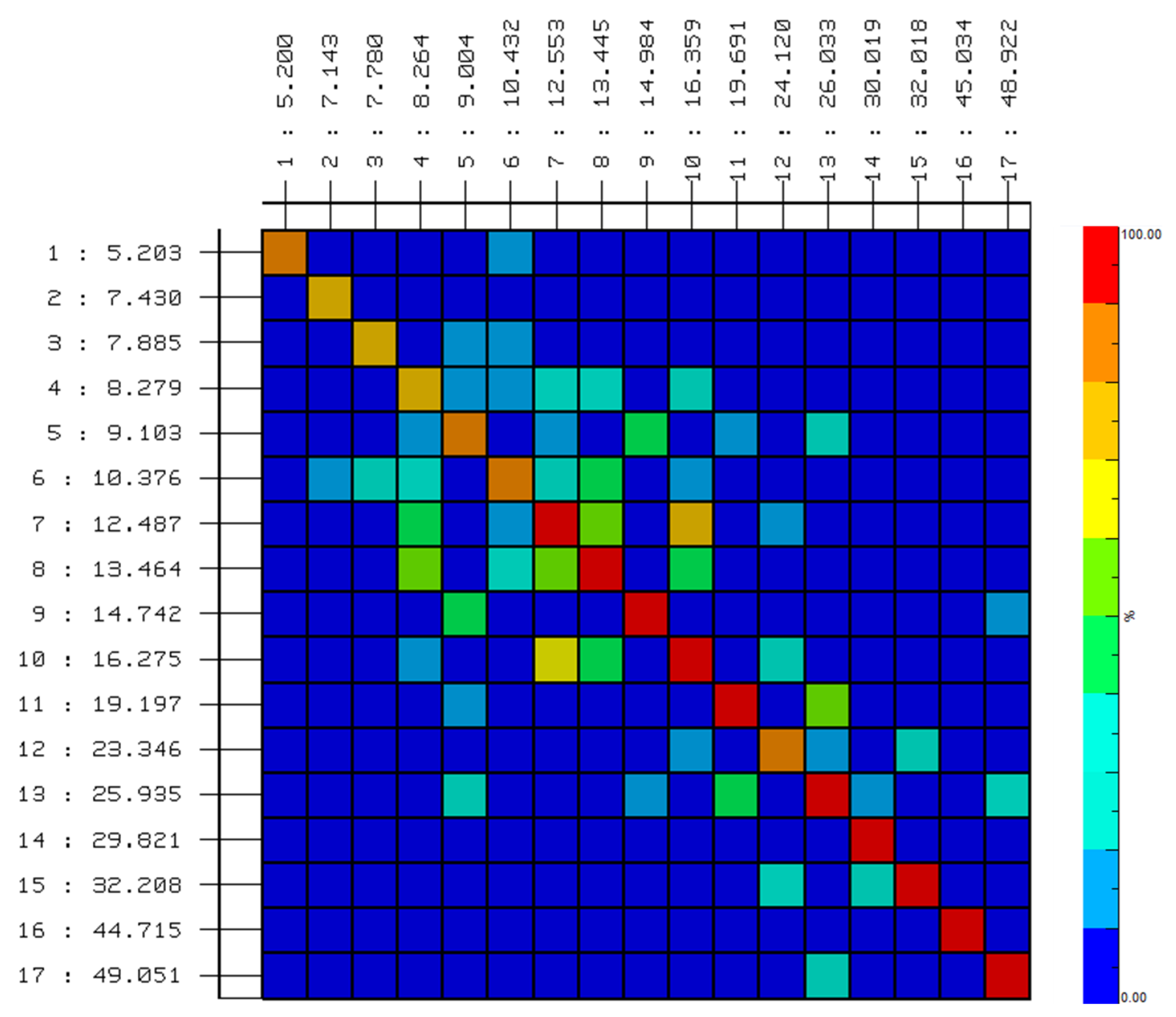
- Looking at the Cross MAC matrix it is possible to see that the differences in the mode shapes are limited to the low frequencies mode shapes and mainly the wing torsional modes, due to the position of the moving masses positioned on the wing tip.
- Based on the GVT data, it appears that the presence of a light non-symmetry in the real model makes it difficult to measure separate global symmetric and anti-symmetric torsional modes. They appear as two different modes at about the same frequency, involving each wing half separately. This generated a poor correlation in the Cross-MAC matrices, as reported in Figure 6b,c.
4. Preliminary Experimental Flutter Test
5. Structural Models
6. Model Updating Strategy
6.1. Optimization Problem Setup
- Many optimizers give the possibility to base the error to minimize many kinds of response variables and flutter velocity as well. Even if the scope of these activities is to capture the aeroelastic behavior with special attention on the flutter point, a purely structural-based formulation has been preferred. A restricted number of variables coming into play can guarantee a better convergence and stronger robustness of the results. The aeroelastic effects have been recovered in a second phase. Thus, the objective function is defined to minimize the differences in the natural frequencies and the differences in the mode shapes between the numerical model and the GVT results.
- The model configuration subjected to optimization has been limited only to the anti-flutter mass in backward position, which is the one prone to flutter. It would have been possible to carry out a double optimization on both configurations, but the actual difference between the two is due to the position of a single mass. In this way, the second mass configuration could be used as a check for the correctness of the optimal solution.
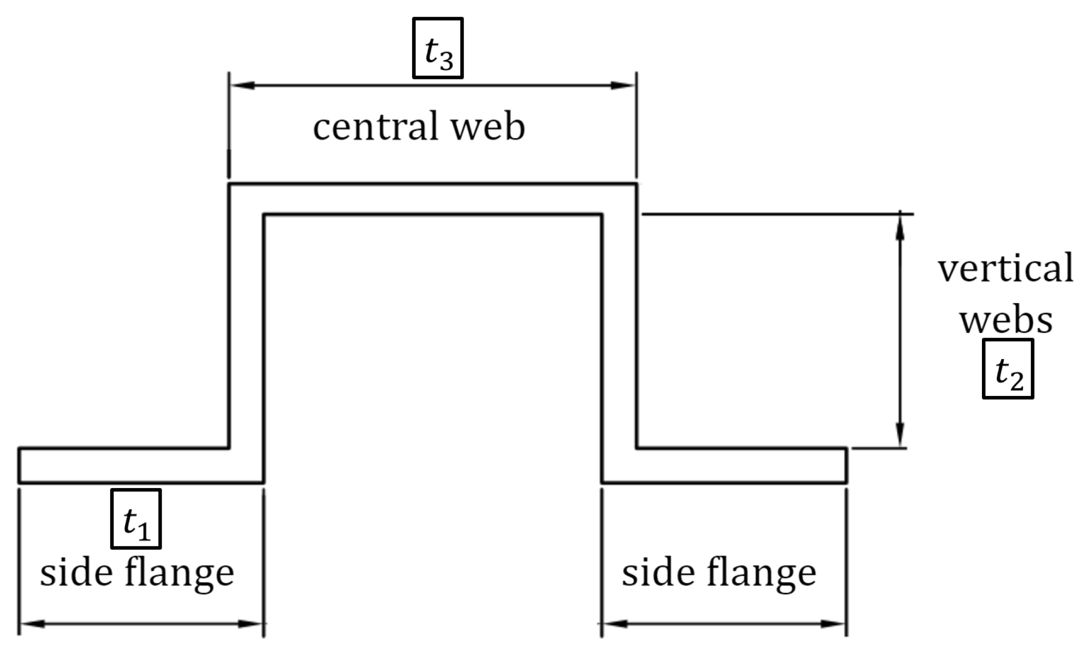
- is the volume relating to part 1 of the omega-shaped spar with nominal values;
- is the total volume in the nominal configuration;
- is the nominal thickness relating to part 1 of the omega-shaped spar;
- is the density in nominal configuration of the spar material.
6.2. Updating Phase
7. Correlation and Updating Results
Modal Correlation
Natural Frequencies Correlation
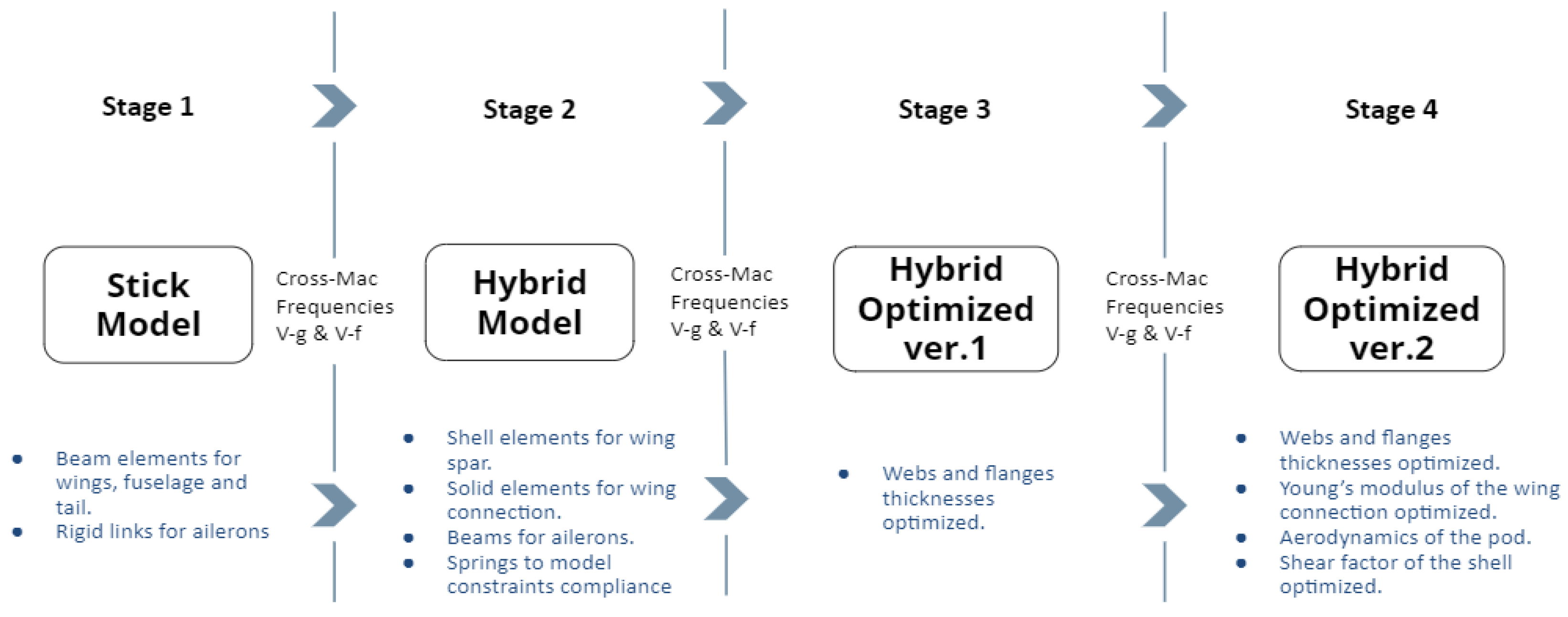
- Decreasing the Young modulus of the wing root connection elements allows us to decrease the first bending frequency.
- Decreasing the Young modulus or the thickness of the top flange of the spar mainly decreases the bending frequency.
- Changing the webs and flanges thicknesses of the spar impact on the torsional frequencies.
- Transverse shear flexibility set in order to have an infinitely rigid in transverse direction plate and trying to increase the torsional stiffness of the wing.
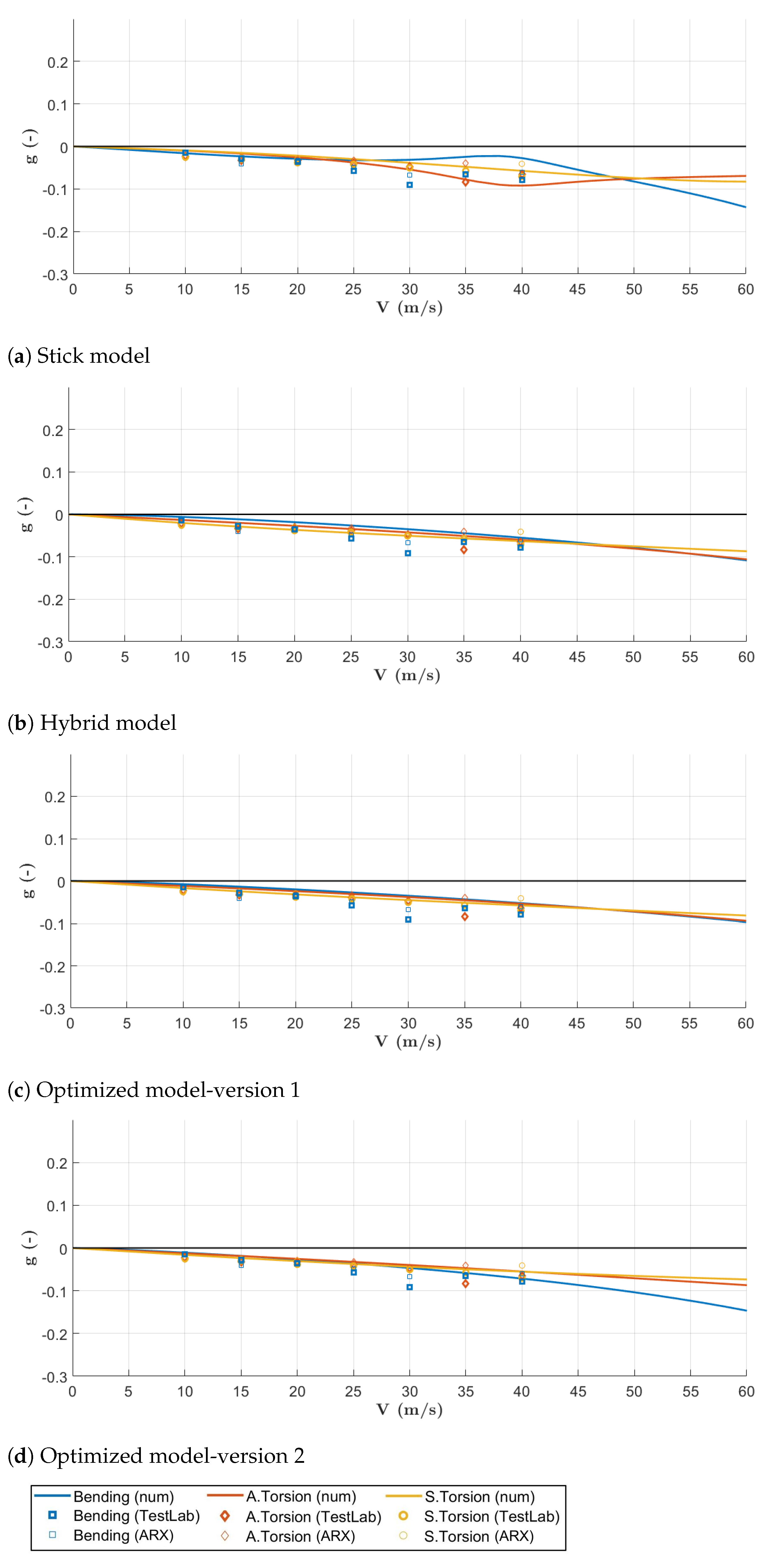
- Classical and not burdensome slender body aerodynamics formulation of the pod was introduced during the flutter analysis, to better reproduce the flutter behavior of the updated model.
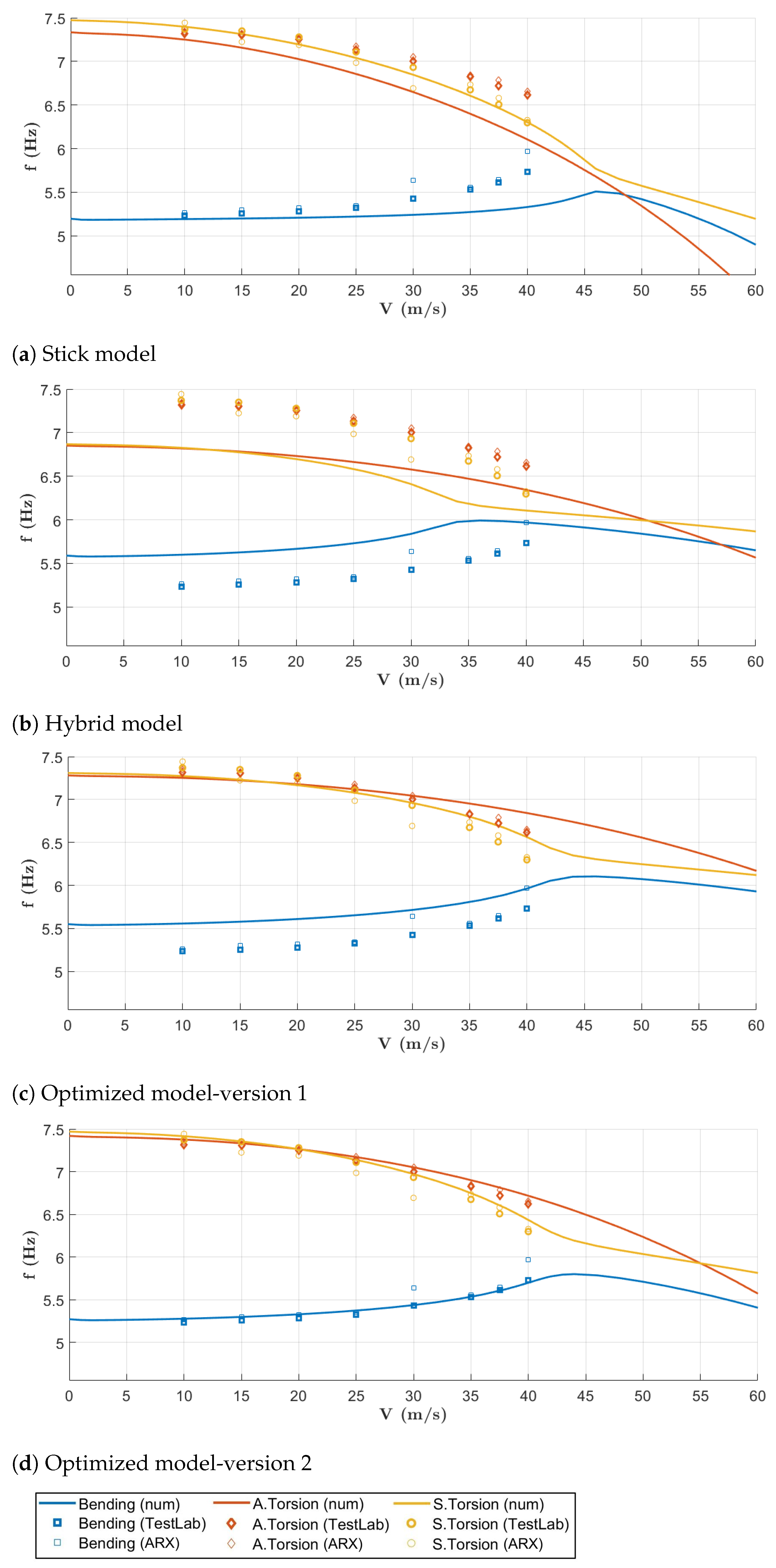
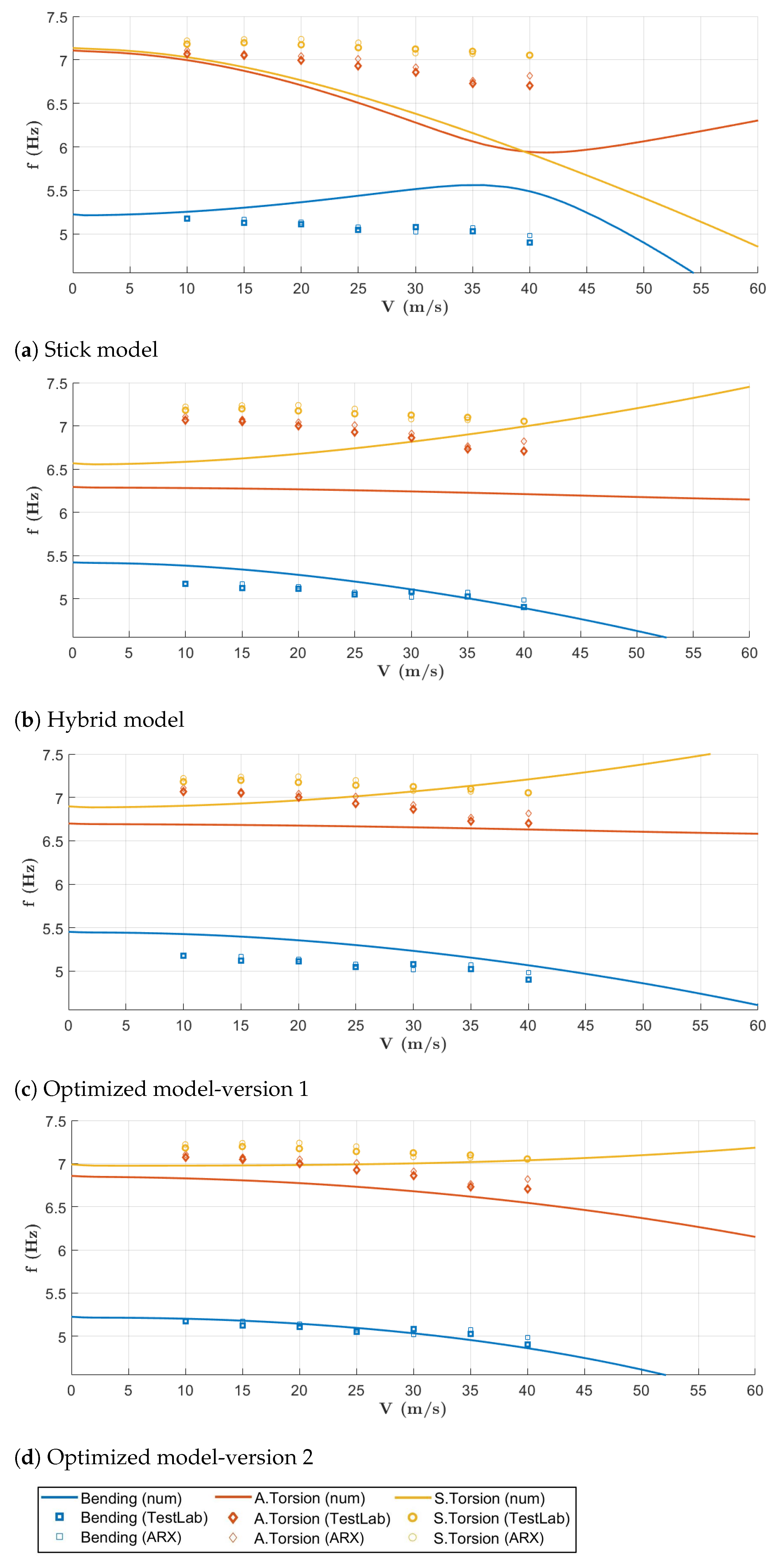
- With the last optimization run, the error committed on the modal frequencies falls below an adequate threshold, thus achieving an excellent level.
- Starting from Hybrid model, the updating process has managed to reduce the error at every step, as can be seen in Table 7. The algorithm has impacted the target frequencies of 0.72% for the 1st symmetric bending, 6.28% for the 1st anti-symmetric torsional, and 6.4% for the 1st symmetric torsional, during the first optimization loop; the values were 5.05%, 1.92%, and 2.19% during the second loop.
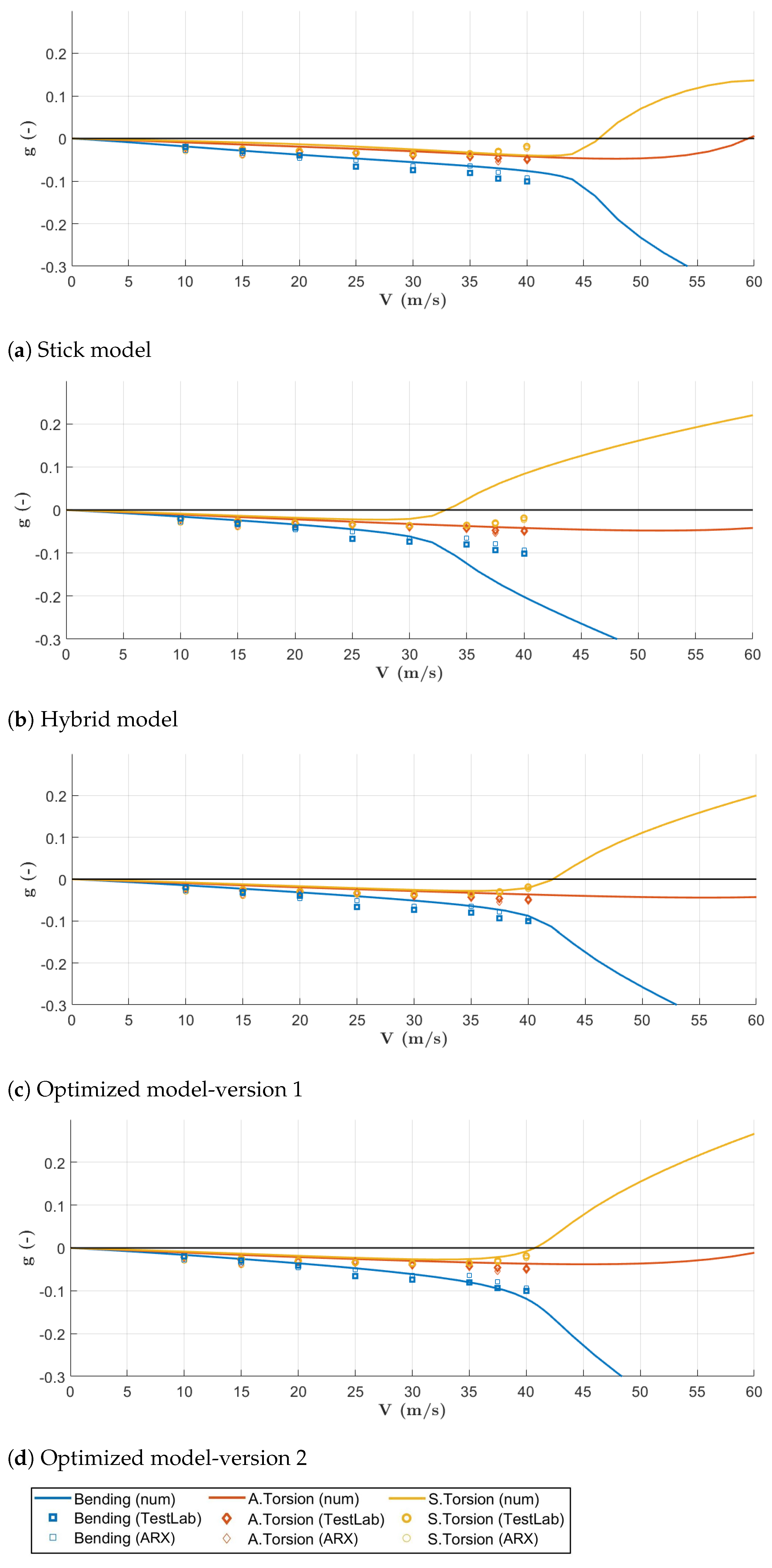
- The 1st first bending mode has been captured very well, both in terms of frequency and shape. This is very important because the flutter mechanism involves the exactly 1st bending and the 2nd torsional (mode # 3).
- Due to the presence of two split torsional modes, as identified during the GVT campaign and reported Figure 12b,c, due to the fact that the actual wind tunnel model is not perfectly symmetric, the correlation results are still poor.
8. Conclusions
Author Contributions
Funding
Institutional Review Board Statement
Informed Consent Statement
Acknowledgments
Conflicts of Interest
Abbreviations
| CG | Center of Gravity |
| DOF | Degree of Freedom |
| DLM | Doublet-Lattice Method |
| FEM | Finite Element Method |
| FRF | Frequency Response Function |
| MAC | Modal Assurance Criterion |
| X-DIA | eXperimental Dipartimento di Ingegneria Aerospaziale |
References
- Bisplinghoff, R.; Ashley, H.; Halfman, R. Aeroelasticity; Dover Publications, Inc.: Mineola, NY, USA, 1955; Chapters 12–13. [Google Scholar]
- Miller, S.; Vio, G.A.; Cooper, J.E.; Vale, J.; da Luz, L.; Gomes, A.; Lau, F.; Suleman, A.; Cavagna, L.; De Gaspari, A.; et al. SMorph—Smart Aircraft Morphing Technologies Project. In Proceedings of the 51th AIAA/ASME/ASCE/AHS/ASC Structures, Structural Dynamics and Materials (SDM) Conference, Orlando, FL, USA, 12–15 April 2010. [Google Scholar] [CrossRef]
- Pankonien, A.M.; Durscher, R.; Bhagat, N. Parametric 3D-Printable Flutter Model for Constrained Aeroelastic Scaling. In Proceedings of the AIAA Scitech 2019 Forum, San Diego, CA, USA, 7–11 January 2019. [Google Scholar]
- Livne, E. Aircraft active flutter suppression: State of the art and technology maturation needs. J. Aircr. 2018, 55, 410–452. [Google Scholar] [CrossRef]
- Bond, V.L.; Canfield, R.A.; Suleman, A.; Blair, M. Aeroelastic Scaling of a Joined Wing for Nonlinear Geometric Stiffness. AIAA J. 2012, 50, 513–522. [Google Scholar] [CrossRef]
- Pereira, P.; Almeida, L.; Suleman, A.; Bond, V.; Canfield, R.; Blair, M. Aeroelastic Scaling and Optimization of a Joined-Wing Aircraft Concept. In Proceedings of the 48th AIAA/ASME/ASCE/AHS/ASC Structures, Structural Dynamics, and Materials Conference, Honolulu, HI, USA, 23–26 April 2007. [Google Scholar] [CrossRef]
- Moreno, C.P.; Gupta, A.; Pfifer, H.; Taylor, B.; Balas, G.J. Structural model identification of a small flexible aircraft. In Proceedings of the 2014 American Control Conference, Portland, OR, USA, 4–6 June 2014; pp. 4379–4384. [Google Scholar] [CrossRef]
- Meddaikar, Y.M.; Dillinger, J.; Klimmek, T.; Krueger, W.; Wüstenhagen, M.; Kier, T.M.; Hermanutz, A.; Hornung, M.; Rozov, V.; Breitsamter, C.; et al. Aircraft Aeroservoelastic Modelling of the FLEXOP Unmanned Flying Demonstrator. In Proceedings of the AIAA Scitech 2019 Forum, San Diego, CA, USA, 7–11 January 2019; American Institute of Aeronautics and Astronautics: San Diego, CA, USA, 2019. [Google Scholar] [CrossRef] [Green Version]
- Takarics, B.; Patartics, B.; Luspay, T.; Vanek, B.; Roessler, C.; Bartaševičius, J.; Koeberle, S.J.; Hornung, M.; Teubl, D.; Pusch, M.; et al. Active Flutter Mitigation Testing on the FLEXOP Demonstrator Aircraft. In Proceedings of the AIAA Scitech 2020 Forum, Orlando, FL, USA, 6–10 January 2020; American Institute of Aeronautics and Astronautics: Orlando, FL, USA, 2020. [Google Scholar] [CrossRef] [Green Version]
- Wüstenhagen, M.; Süelözgen, O.; Ackermann, L.; Bartaševičius, J. Validation and Update of an Aeroservoelastic Model based on Flight Test Data. In Proceedings of the 2021 IEEE Aerospace Conference, Big Sky, MT, USA, 6–13 March 2021; pp. 1–18. [Google Scholar] [CrossRef]
- Zhao, W.; Gupta, A.; Miglani, J.; Regan, C.D.; Kapania, R.K.; Seiler, P.J. Finite Element Model Updating of Composite Flying-wing Aircraft using Global/Local Optimization. In Proceedings of the AIAA Scitech 2019 Forum, San Diego, CA, USA, 7–11 January 2019; American Institute of Aeronautics and Astronautics: San Diego, CA, USA, 2019. [Google Scholar] [CrossRef]
- Ricci, S.; Scotti, A.; Cecrdle, J.; Malecek, J. Active control of three-surface aeroelastic model. J. Aircr. 2008, 45, 1002–1013. [Google Scholar] [CrossRef]
- De Gaspari, A.; Ricci, S.; Riccobene, L.; Scotti, A. Active aeroelastic control over a multisurface wing: Modeling and wind-tunnel testing. AIAA J. 2009, 47, 1995–2010. [Google Scholar] [CrossRef]
- Ghiringhelli, G.; Lanz, M.; Mantegazza, P. A comparison of methods used for the identification of flutter from experimental data. J. Sound Vib. 1987, 119, 39–51. [Google Scholar] [CrossRef]
- Marchetti, L.; De Gaspari, A.; Riccobene, L.; Toffol, F.; Fonte, F.; Ricci, S.; Mantegazza, P.; Livne, E.; Hinson, K.A. Active Flutter Suppression Analysis and Wind Tunnel Studies of a Commercial Transport Configuration. In Proceedings of the AIAA Scitech 2020 Forum, Orlando, FL, USA, 6–10 January 2020; p. 1677. [Google Scholar] [CrossRef]
- French, M.; Kolonay, R.M. Demonstration of structural optimization applied to wind-tunnel model design. J. Aircr. 1992, 29, 966–968. [Google Scholar] [CrossRef]
- MSC. Nastran Design Sensitivity and Optimization User’s Guide; MSC/Software Corporation: Santa Ana, CA, USA, 2005. [Google Scholar]
- DeGaspari, A.; Mannarino, A.; Mantegazza, P. A Dual Loop Strategy For The Design of a Control Surface Actuation System with Nonlinear Limitations. Mech. Syst. Signal Process. 2017, 90, 334–349. [Google Scholar] [CrossRef]
- Inman, D.J.; Singh, R.C. Engineering Vibration; Prentice Hall: Englewood Cliffs, NJ, USA, 1994; Volume 3. [Google Scholar]
- Peeters, B.; Guillaume, P.; Van der Auweraer, H.; Cauberghe, B.; Verboven, P.; Leuridan, J. Automotive and aerospace applications of the PolyMAX modal parameter estimation method. Proc. IMAC 2004, 22, 1. [Google Scholar]
- Schwarz, B.J.; Richardson, M.H. Experimental modal analysis. CSI Reliab. Week 1999, 35, 1–12. [Google Scholar]
- Rockling, G.Y. A comparison of H1, H2 and HV frequency response functions. In Proceedings of the 3rd International Modal Analysis Conference, Orlando, FL, USA, 28–31 January 1985; pp. 272–278. [Google Scholar]
- Larson, C.; Zimmerman, D.; Marek, E. A comparative study of metrics for modal pre-test sensor and actuator selection using the JPL/MPI testbed truss. In Proceedings of the Dynamics Specialists Conference, Hilton Head, SC, USA, 21–22 April 1994; p. 1689. [Google Scholar]
- Ewins, D. Model validation: Correlation for updating. Sadhana 2000, 25, 221–234. [Google Scholar] [CrossRef]
- Peeters, B.; Van der Auweraer, H.; Guillaume, P.; Leuridan, J. The PolyMAX frequency-domain method: A new standard for modal parameter estimation? Shock Vib. 2004, 11, 395–409. [Google Scholar] [CrossRef]
- Diversi, R.; Guidorzi, R.; Soverini, U. Identification of ARX and ARARX models in the presence of input and output noises. Eur. J. Control. 2010, 16, 242–255. [Google Scholar] [CrossRef]
- MSC. Nastran Aeroelastic Analysis User’s Guide; MSC/Software Corporation: Santa Ana, CA, USA, 2005. [Google Scholar]
- Prananta, B.; Kanakis, T.; Vankan, J.; van Houten, R. Model updating of finite element model using optimisation routine. Aircr. Eng. Aerosp. Technol. 2016, 88, 665–675. [Google Scholar] [CrossRef]
- Mottershead, J.; Friswell, M. Model Updating In Structural Dynamics: A Survey. J. Sound Vib. 1993, 167, 347–375. [Google Scholar] [CrossRef]
- Göge, D. Automatic updating of large aircraft models using experimental data from ground vibration testing. Aerosp. Sci. Technol. 2003, 7, 33–45. [Google Scholar] [CrossRef]
- Friswell, M.; Mottershead, J.E. Finite Element Model Updating in Structural Dynamics; Solid Mechanics and Its Applications; Springer: Dordrecht, The Netherlands, 1995. [Google Scholar] [CrossRef]
- Hassig, H.J. An approximate true damping solution of the flutter equation by determinant iteration. J. Aircr. 1971, 8, 885–889. [Google Scholar] [CrossRef]






| ID | Mass forward (Hz) | Mass Rear (Hz) | ΔFrequency (%) | Shape |
|---|---|---|---|---|
| 1 | 5.20 | 5.20 | 0.00 | 1st S-BEN |
| 2 | 7.14 | 7.43 | 4.06 | Left wing 1st TOR |
| 3 | 7.78 | 7.88 | 1.29 | Right wing 1st TOR |
| 4 | 8.26 | 8.28 | 0.24 | 1st S-BEN htail + 1st S-BEN wing |
| 5 | 9.00 | 9.10 | 1.11 | 1st AS-BEN htail + 1st S-BEN wing |
| 6 | 10.43 | 10.38 | −0.48 | 1st S-BEN htail + 1st S-BEN wing |
| 7 | 12.55 | 12.49 | −0.48 | 1st S-TOR htail torsion + 1st S-TOR wing |
| 8 | 13.45 | 13.46 | 0.07 | 1st S-BEN htail |
| 9 | 14.98 | 14.74 | −1.60 | 2nd AS-BEN wing and 2nd AS-BEN htail |
| 10 | 16.36 | 16.28 | −0.49 | 2nd S-TOR wing + 2nd S-BEN htail |
| 11 | 19.69 | 19.20 | −2.49 | 2nd AS-TOR wing + 2nd AS-BEN htail + |
| + 1st AS-BEN vtail | ||||
| 12 | 24.12 | 23.35 | −3.19 | 2nd AS-TOR wing + 2nd S-BEN htail |
| ID | Mass forward (Hz) | Mass Rear (Hz) | ΔDamping (%) |
|---|---|---|---|
| 1 | 0.13 | 0.17 | 30.77 |
| 2 | 1.22 | 1.14 | −6.56 |
| 3 | 1.08 | 0.75 | −30.56 |
| 4 | 1.03 | 1.30 | 26.21 |
| 5 | 1.65 | 3.07 | 86.06 |
| 6 | 0.48 | 0.39 | −18.75 |
| 7 | 1.00 | 0.90 | −10.00 |
| 8 | 2.65 | 2.73 | 3.02 |
| 9 | 1.60 | 1.23 | −23.13 |
| 10 | 0.83 | 0.85 | 2.41 |
| 11 | 0.54 | 0.57 | 5.56 |
| 12 | 0.65 | 0.65 | 0.00 |
| Speeds (m/s) | |||||||||
|---|---|---|---|---|---|---|---|---|---|
| Backward mass | 0 | 10 | 15 | 20 | 25 | 30 | 35 | 37.5 | 40 |
| Forward mass | 0 | 10 | 15 | 20 | 25 | 30 | 35 | 40 | |
| Model | Mass (kg) | (m) | (m) | (m) | |
|---|---|---|---|---|---|
| Stick | 59.42 | −0.784 | 0 | 0.077 | |
| Hybrid | 59.49 | −0.777 | 0 | 0.077 | |
| Opt ver.1 | 59.49 | −0.777 | 0 | 0.077 | |
| Opt ver.2 | 59.46 | −0.779 | 0 | 0.077 | |
| 14.52 | 25.65 | 37.17 | 0 | 2.94 | −0.05 |
| 14.52 | 25.73 | 37.23 | 0 | 2.92 | 0 |
| 14.55 | 25.74 | 37.28 | 0 | 2.92 | 0 |
| 14.53 | 25.74 | 37.26 | 0 | 2.92 | 0 |
| Design Variables | Initial Value | Final Value |
|---|---|---|
| 1st Optimization loop | ||
| 3.4 mm | 4 mm | |
| 3.4 mm | 4 mm | |
| 3 mm | 2.59 mm | |
| 2nd Optimization loop | ||
| 4 mm | 4.06 mm | |
| 4 mm | 4.06 mm | |
| 2.59 mm | 2.61 mm | |
| E of wing-fuselage connection block | 7 GPa | 4.5 GPa |
| E of the wingspar shell elements | 7.2 GPa | 7 GPa |
| GVT # | Freq (Hz) | Stick # | Freq (Hz) | Error (%) | Hybrid # | Freq (Hz) | Error (%) |
|---|---|---|---|---|---|---|---|
| 1 | 5.20 | 1 | 5.19 | 0.06 | 1 | 5.59 | 7.49 |
| 2 | 7.43 | 2 | 7.33 | 1.29 | 2 | 6.85 | 7.78 |
| 3 | 7.88 | 3 | 7.47 | 5.17 | 3 | 6.87 | 12.84 |
| 5 | 9.10 | 6 | 8.94 | 8.21 | 5 | 8.93 | 1.79 |
| 6 | 10.38 | 5 | 8.79 | 3.37 | 7 | 11.10 | 6.91 |
| 7 | 12.49 | 9 | 12.25 | 1.94 | 8 | 12.19 | 2.40 |
| 8 | 13.46 | 10 | 14.43 | 7.23 | 11 | 14.42 | 7.13 |
| Mode Type | GVT (Hz) | Stick (Hz) | Hybrid (Hz) | Opt 1 (Hz) | Opt 2 (Hz) |
|---|---|---|---|---|---|
| 1st symm. bending | 5.20 | 5.19 | 5.59 | 5.55 | 5.27 |
| 1st anti-s torsional | 7.43 | 7.33 | 6.85 | 7.28 | 7.42 |
| 1st symm. torsional | 7.88 | 7.47 | 6.87 | 7.31 | 7.47 |
| Error (%) | |||||
| 1st symm. bending | - | 0.06 | 7.49 | 6.72 | 1.34 |
| 1st anti-s torsional | - | 1.29 | 7.78 | 2.02 | 0.13 |
| 1st symm. torsional | - | 5.17 | 12.84 | 7.23 | 5.20 |
| GVT | Stick | Hybrid | Opt 1 | Opt 2 | |
|---|---|---|---|---|---|
| 41.5 | 45.5 | 32.5 | 42 | 40.5 | |
| - | 9.6 | 21.7 | 1.2 | 2.4 | |
| 6.2 | 5.73 | 6.47 | 6.41 | 6.41 | |
| - | 7.58 | 4.35 | 3.38 | 3.38 |
| Mode type | GVT (Hz) | Stick (Hz) | Hybrid (Hz) | Opt 1 (Hz) | Opt 2 (Hz) |
|---|---|---|---|---|---|
| 1st symm. bending | 5.20 | 5.22 | 5.43 | 5.45 | 5.22 |
| 1st anti-s. torsional | 7.14 | 7.11 | 6.29 | 6.69 | 6.85 |
| 1st symm. torsional | 7.78 | 7.14 | 6.57 | 6.9 | 6.98 |
| Error (%) | |||||
| 1st symm. bending | - | 0.38 | 4.4 | 4.8 | 0.38 |
| 1st anti-s. torsional | - | 0.42 | 11.9 | 6.3 | 4.06 |
| 1st symm. torsional | - | 8.23 | 15.55 | 11.31 | 10.28 |
Publisher’s Note: MDPI stays neutral with regard to jurisdictional claims in published maps and institutional affiliations. |
© 2021 by the authors. Licensee MDPI, Basel, Switzerland. This article is an open access article distributed under the terms and conditions of the Creative Commons Attribution (CC BY) license (https://creativecommons.org/licenses/by/4.0/).
Share and Cite
Di Leone, D.; Lo Balbo, F.; De Gaspari, A.; Ricci, S. Model Updating and Aeroelastic Correlation of a Scaled Wind Tunnel Model for Active Flutter Suppression Test. Aerospace 2021, 8, 334. https://doi.org/10.3390/aerospace8110334
Di Leone D, Lo Balbo F, De Gaspari A, Ricci S. Model Updating and Aeroelastic Correlation of a Scaled Wind Tunnel Model for Active Flutter Suppression Test. Aerospace. 2021; 8(11):334. https://doi.org/10.3390/aerospace8110334
Chicago/Turabian StyleDi Leone, Domenico, Francesco Lo Balbo, Alessandro De Gaspari, and Sergio Ricci. 2021. "Model Updating and Aeroelastic Correlation of a Scaled Wind Tunnel Model for Active Flutter Suppression Test" Aerospace 8, no. 11: 334. https://doi.org/10.3390/aerospace8110334
APA StyleDi Leone, D., Lo Balbo, F., De Gaspari, A., & Ricci, S. (2021). Model Updating and Aeroelastic Correlation of a Scaled Wind Tunnel Model for Active Flutter Suppression Test. Aerospace, 8(11), 334. https://doi.org/10.3390/aerospace8110334


