Article

Climate Impact Mitigation Potential of European Air Traffic in a Weather Situation with Strong Contrail Formation †

1
Institute of Air Transportation Systems, Hamburg University of Technology, 21079 Hamburg, Germany
2
German Aerospace Center, Air Transportation Systems, 21079 Hamburg, Germany
3
German Aerospace Center, Earth-System-Modelling, Institute of Atmospheric Physics, Oberpfaffenhofen, 82334 Wessling, Germany
4
Section Aircraft Noise and Climate Effects, Faculty of Aerospace Engineering, Delft University of Technology, 2628 HS Delft, The Netherlands
*
Author to whom correspondence should be addressed.
This paper is an extended version of our abstract published at 3rd ECATS Conference, Virtual Conference, 13–15 October 2020.
Aerospace 2021, 8(2), 50; https://doi.org/10.3390/aerospace8020050
Submission received: 31 December 2020 / Revised: 7 February 2021 / Accepted: 8 February 2021 / Published: 12 February 2021

Abstract

:
Air traffic contributes to anthropogenic global warming by about 5% due to CO2 emissions and non-CO2 effects, which are primarily caused by the emission of NOx and water vapor as well as the formation of contrails. Since—in the long term—the aviation industry is expected to maintain its trend to grow, mitigation measures are required to counteract its negative effects upon the environment. One of the promising operational mitigation measures that has been a subject of the EU project ATM4E is climate-optimized flight planning by considering algorithmic climate change functions that allow for the quantification of aviation-induced climate impact based on the emission’s location and time. Here, we describe the methodology developed for the use of algorithmic climate change functions in trajectory optimization and present the results of its application to the planning of about 13,000 intra-European flights on one specific day with strong contrail formation over Europe. The optimization problem is formulated as bi-objective continuous optimal control problem with climate impact and fuel burn being the two objectives. Results on an individual flight basis indicate that there are three major classes of different routes that are characterized by different shapes of the corresponding Pareto fronts representing the relationship between climate impact reduction and fuel burn increase. On average, for the investigated weather situation and traffic scenario, a climate impact reduction in the order of 50% can be achieved by accepting 0.75% of additional fuel burn. Higher mitigation gains would only be available at much higher fuel penalties, e.g., a climate impact reduction of 76% associated with a fuel penalty of 12.8%. However, these solutions represent much less efficient climate impact mitigation options.

1. Introduction

Global air traffic has been growing over the past decades and was able to withstand a number of global crises despite temporary declines in flight movements. Therefore, air travel demand is expected to grow in the long term. Since the fuel performance improvement rates due to a continuous development of enhanced aircraft technologies are not expected to exceed growth rates, aviation’s impact on global gaseous emissions and climate is expected to increase.
Apart from CO2 emissions, air traffic is also responsible for non-CO2 effects, due to the emission of nitrogen oxides and water vapor as well as the formation of contrails, which change the concentration of radiative forcing agents in the atmosphere and hence have an impact on the climate. Overall, aviation’s contribution to anthropogenic climate change is estimated to be about 5%, of which approximately two-thirds can be attributed to the non-CO2 effects [1]. Therefore, mitigation actions have to be introduced as soon as possible considering both CO2 and non-CO2 effects together. The latter ones are strongly dependent on the geographic location, altitude, time of the day, and the current atmospheric background conditions. Consequently, the avoidance of climate-sensitive regions, which are characterized by a particularly high share of non-CO2 emissions on the climate impact, is considered to be a promising means.
There have been several approaches to climate-optimized routing, which vary in the considered emission species, the geographic variability of the effects, the climate metric used, and the degrees of freedom in the trajectory optimization. Schumann et al. [2] found that flight-level changes of 2000 ft (610 m) up or down may significantly reduce the climate impact caused by contrails without the adaption of the lateral aircraft routing. Additional climate impact mitigation potential by avoiding contrail sensitive regions, both laterally and vertically at the same time, was identified by Sridhar et al., Hartjes et al., and Zou et al. [3,4,5].
In the course of the project REACT4C funded by the European Commission, climate change functions (CCFs) for eight different North Atlantic weather patterns have been developed based on detailed simulations with atmospheric chemistry models [6]. These CCFs measure the climate impact of CO2, NOx, and water vapor as well as contrails and depend on the emission location and time [7,8]. Considering the current airspace structure, by laterally and vertically optimizing air traffic in the North Atlantic region with regard to climate impact based on CCFs, total climate impact savings of up to 60% for westbound and 35% for eastbound traffic at a cost penalty between 10% and 15% have been estimated for one specific winter day [9]. Averaged over all eight North Atlantic weather patterns, a climate impact mitigation potential in the order of 20% at a cost penalty of about 7% has been determined [10]. By assuming free flight conditions, climate impact reductions of up to 30% related with 8% additional costs have been identified as average over all weather patterns. However, a climate impact reduction of 24% can already be achieved with cost increases below 1% [11].
The European project ATM4E, carried out in the SESAR Exploratory Research programme, was dedicated to the scientific investigation of the potential of optimizing flights in the European airspace with respect to their climate impact already during flight planning [12]. The estimation of detailed CCFs based on complex climate chemistry model simulations, as determined in the course of the REACT4C project, is not feasible in real time due to the large computational effort. Therefore, one major goal of the ATM4E project was the development of algorithmic climate change functions (aCCFs), which allow for a fast and efficient computation of the climate impact of different emission species purely based on available weather (forecast) data. Thanks to these aCCFs, it was possible to perform a fast-time flight planning aiming at reduced climate impact for any given weather situation.
Within this study, we describe the methodology developed for the use of aCCFs in trajectory optimization for flight planning (see Section 2) and present results for a traffic scenario that consists of about 13,000 intra-European flights on a selected day (see Section 3). Finally, the results are discussed, and an outlook is given (see Section 4).

2. Materials and Methods

Below, the concept of algorithmic climate change functions is illustrated (see Section 2.1). On this basis, the estimation of climate optimized aircraft trajectories is elaborated (see Section 2.2).

2.1. Algorithmic Climate Change Functions

Climate change functions (CCFs) allow for quantifying the global climate impact of local aircraft emissions as a function of emission location and time [7,13]. The aCCFs consider both CO2 and non-CO2 effects and measure global climate impact using the average temperature response integrated over a time period of 20 years (ATR20). By design, aCCFs allow for a fast-time calculation of the climate impact of ozone and methane changes resulting from NOx emissions, water vapor emissions, and persistent contrail formation using standard weather forecast data, which is already available for flight planning.
The water vapor and nitrogen oxide aCCFs were created by applying correlation analyses using the CCFs estimated in the course of the project REACT4C and are based on meteorological parameters, which show a reasonable statistical significance [14,15,16,17]. For the prediction of the climate impact of water vapor, the potential vorticity was found to be best suited to correlate the effects. The water vapor aCCF on 18 December 2015, 6.00 p.m. UTC on flightlevel 390 and at 48° N is shown as contour in Figure 1a and Figure 2a. On flightlevel 390, strong variations between 0.4 and 1.7 × 10⁻¹⁵ K/kgFuel are observed in the European domain. However, Figure 2a indicates only small vertical gradients of the water vapor aCCF for the investigated weather pattern.
The warming effect of ozone which is caused by the emission of NOx is modeled as a function of the local temperature and the geopotential. The cooling effects of the methane reductions resulting from NOx emissions were captured by a relationship, which includes the geopotential and the amount of incoming solar radiation at the top of the atmosphere. Figure 1b shows the NOx aCCF over Europe on 18 December 2015, 6.00 p.m. UTC on flightlevel 390, which varies between 2.0 and 2.3 × 10⁻¹² K/kgNOx. For this weather situation, the NOx aCCF shows minimum values in the order of 1.5 × 10⁻¹² K/kgNOx at an altitude of 10,000 m as illustrated in Figure 2b. With rising altitudes, the NOx aCCF is increasing strongly to values in the order of 2.3 × 10⁻¹² K/kgNOx.
Contrail aCCFs were derived separately for night-time contrails and day-time contrails, since the net contrail climate effect is hugely influenced by the time of the day they occur. It was found that the local temperature (which strongly determines the amount of contrail ice content) in the case of night-time contrails and the outgoing infrared radiation in the case of day-time contrails provide reasonable approximations for the estimation of the climate impact. For both day-time and night-time contrails, the Schmidt–Appleman criterion is applied, which uses temperature and humidity information in order to predict regions where persistent contrails are expected to form [18]. According to Figure 1c, the resulting contrail aCCF on 18 December 2015, 6.00 p.m. UTC on flightlevel 390 shows a strong warming area from the East of France over Switzerland to the North of Italy and a second warming area over Latvia, Lithuania, and Belarus. According to Figure 2c, the warming area over France has a large vertical dimension between 9000 m and 12,000 m. Additionally, cooling areas are observed in the South of Great Britain, Poland, and Finland.

2.2. Trajectory Optimization

In the following, the methodology to identify climate optimized aircraft trajectories using the Trajectory Optimization Module (TOM) is presented. Therefore, the general optimal control problem formulation is introduced (see Section 2.2.1). On this basis, control, state, and path vectors as well as the objective function of the optimization are specified (see Section 2.2.2 and Section 2.2.3). Finally, the dynamic constraints reflecting the aircraft performance characteristics are defined (see Section 2.2.4).

2.2.1. General Optimal Control Problem Formulation

In the course of this study, the Trajectory Optimization Module, which uses optimal control techniques in order to determine climate optimized aircraft trajectories, is used [19]. Therefore, aircraft’s motion is described as the temporal evolution of state variables x(t), which can be modified using control variables u(t). Optimized aircraft trajectories are obtained by finding a control input u(t), which minimizes the objective function J (see Equation (1)). In parallel, dynamic constraints (see Equation (2)) as well as control, state, and path limitations (see Equations (3)–(7)) have to be considered. In order to solve the resulting optimal control problem, the MATLAB toolbox GPOPS-II is used [20]. Following a direct approach, GPOPS-II converts the continuous optimal control problem into a discrete non-linear programming problem which is then solved with IPOPT [21].
J t , x t , u t =   c Υ · Υ t 0 , t f , x t 0 , x t f + c Ψ · t 0 t f Ψ x t , u t , t   d t
x ˙ t = f x t , u t , t
x t 0 = x min , 0 ; x max , 0
x t f = x min , f ; x max , f
x t = x m i n ; x m a x
u t = u m i n ; u m a x
p t = p m i n ; p m a x

2.2.2. Choice of State, Control, and Path Vectors

The aircraft state is described as x = [ λ , φ , H , v TAS , m , m i ]T. The location of the aircraft is characterized by its longitude λ , latitude φ , and altitude H . Additionally, v TAS represents the true airspeed, m represents the aircraft mass, and m i represents the cumulative emissions released by the engine (i CO2, H2O, NOx). The motion of the aircraft can be varied using the control vector u = [ χ H ,   v ˙ TAS ,   τ ]T where χ H denotes the heading angle, v ˙ TAS denotes the linear acceleration, and τ denotes the relative thrust (minimum thrust: τ = 0 , maximum thrust: τ = 1 ). Additionally, the path vector is defined as p = [ H p ,   Ma , v CAS , c L , r e l ]T in order to be able to consider further boundary conditions with regard to the pressure altitude H p , the Mach number Ma , the calibrated airspeed v CAS , and the relative lift coefficient c L , r e l (maximum lift: c L , r e l = 1 ).

2.2.3. Objective Function

In order to determine trajectories that are Pareto optimal with respect to fuel burn and climate impact, the objective function is expressed as the weighted sum of climate impact (curly brackets) and fuel burn (squared brackets). Both climate impact as well as fuel burn are normalized with respect to the corresponding reference values of the minimum fuel burn trajectory ( ATR ref , m fuel , ref ). The climate impact is obtained as the temporal integral of the product of the aCCFs (see Section 2.1) and the associated emission flow m ˙ i for CO2, NOx, and H2O or the true airspeed v TAS in the case of contrail-induced cirrus cloudiness (CIC).
J = c clim · i t 0 t f aCCF i x , t · m ˙ i t d t + t 0 t f aCCF CIC x , t · v TAS t d t · ATR ref 1 + + c fuel · m 0 m f · m fuel , ref 1     ;           i CO 2 ,   NO x , H 2 O  
c clim + c fuel = 1       with       c clim , c fuel 0 , 1
Varying the weights of climate impact and fuel burn ( c clim and c fuel ) yields Pareto-optimal trajectories. Minimum climate impact trajectories are determined with c clim = 1 and minimum fuel burn trajectories are determined with c fuel = 1 .

2.2.4. Dynamic Constraints

The aircraft’s equations of motion are determined assuming a point-mass model with variable mass and three degrees of freedom. Considering the windspeeds u W (direction east) and v W (direction north), a spherical earth with the radius R E and the flight path angle γ ( sin   γ = H ˙ / v TAS ), the temporal derivates of longitude and latitude are estimated according to Equations (10) and (11). Moreover, the vertical speed H ˙ is determined as a function of relative thrust τ , aerodynamic drag D , aircraft speed and acceleration ( v TAS ,   v ˙ TAS ), as well as aircraft mass m based on the Total Energy Model, as shown in Equation (12). Minimum and maximum thrust ( Th max ,   Th min ) and aerodynamic drag D are obtained from EUROCONTROL’s Base of aircraft data (BADA) 4.0 aircraft performance models [22]. The derivative of the true airspeed v TAS has been selected as control input v ˙ TAS (see Section 2.2.2 and Equation (13)). According to Equation (14), the aircraft mass change rate m ˙ is calculated as negative fuel flow FF based on the BADA engine performance characteristics. Finally, the emission flows m ˙ i (i CO2, H2O, NOx) are estimated by multiplying the fuel flow FF with the emission index EI i . For CO2 and H2O emissions, a stoichiometric combustion is assumed, EI NOx is computed based on the EUROCONTROL-modified Boeing Fuel Flow method 2 [23,24].
λ ˙ =   v TAS · cos   γ · sin   χ H + u W R E + H · cos   φ
φ ˙ =   v TAS · cos   γ · cos   χ H + v W R E + H
H ˙ =   τ · Th max Th min + Th min D · v TAS m · g v TAS · v ˙ TAS g
v ˙ TAS = v ˙ TAS
m ˙ = FF
m ˙ i = FF · EI i

3. Results

Below, the chosen reference day for the case study is characterized (see Section 3.1). Then, climate optimized trajectories and corresponding Pareto fronts for exemplary routes are presented (see Section 3.2). Finally, the individual Pareto fronts are consolidated in order to formulate more general statements (see Section 3.3).

3.1. One-Day Case Study of European Air Traffic

Using the modeling approach described in Section 2, the en route sections (i.e., altitude > 10,000 ft) of aircraft trajectories within Europe are optimized with respect to fuel burn and climate impact of CO2 and non-CO2 effects.
As the case study day, 18 December 2015 has been selected, since this day is characterized by a high traffic volume (busiest day in December 2015) with unaffected traffic flows indicated by a low number of weather-, Air Traffic Control (ATC)-, and aerodrome related regulations (seven weather-, seven ATC-, and eight aerodrome-regulations). Additionally, the weather situation is characterized by varying wind speeds from north (high wind speeds) to south (low wind speeds) and shows large persistent contrail formation areas over Central Europe (see Figure 3). Meteorological parameters, which are required for both the aircraft performance calculations (e.g., pressure, temperature, wind speeds) as well as the aCCF evaluation (e.g., temperature, potential vorticity, humidity, incoming solar radiation) are determined based on European Centre for Medium-Range Weather Forecasts (ECMWF) ERA-Interim reanalysis data [25].
The corresponding traffic inventory is extracted from EUROCONTROL’s Demand Data Repository 2 (DDR2) database and contains 28,337 flights. After filtering by restricting to intra-ECAC (European Civil Aviation Conference) flights only and by restricting to flights covered by the BADA 4.0 aircraft performance models, a traffic sample containing 13,276 flights is generated. Although this seems to be a large reduction of flights, the amount of considered available seat kilometers only decreases by about 9%, since especially large Airbus and Boeing aircraft are part of BADA.
Figure 4 shows the cumulative CO2 emissions of the reference air traffic on 18 December 2015 between 11.30 a.m. and 12.00 p.m. UTC (colors) and the location of 1210 aircraft that have been flying at 12.00 pm UTC (black dots). In the reference case, the majority of emissions is released at altitudes between 11,000 m and 12,000 m, latitudes between 40° and 52° N, and longitudes between 15° W and 25° E.

3.2. Results for Individual Routes

Considering both climate impact and economic aspects in the trajectory planning process, approximately 100 Pareto-optimal trajectory options for each route within the traffic sample have been calculated by systematically varying the weighting factors c clim and c fuel according to Equations (8) and (9).
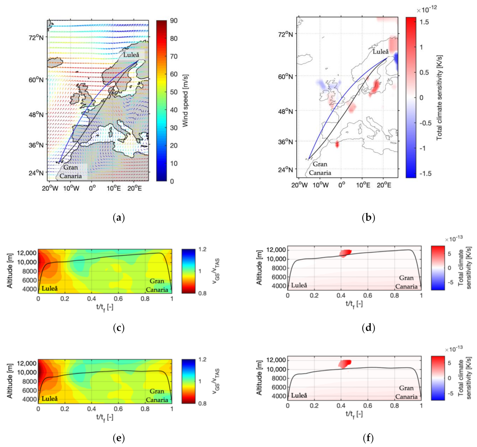
As an example, optimized trajectories are depicted in Figure 5 for the route Luleå–Gran Canaria. As illustrated in Figure 5a, the minimum fuel trajectory (black, c fuel = 1 ) is shifted to the south compared to the orthodrome (blue) in order to avoid strong headwinds. A warming contrail area indicated by a high climate sensitivity is passed at about 48° N/5° E (see Figure 5b). The vertical flight profile of the minimum fuel trajectory along the cross-section of the lateral path indicates a continuous cruise climb trajectory with only minor deviations due to favorable wind conditions (see Figure 5c). Additionally, the trajectory passes through a strong warming area at t/tf = 0.4 (see Figure 5d).
Increasing the importance of the climate impact in the objective function of the optimization by increasing c clim , the trajectories are shifted to reduced altitudes successively. The lateral paths remain almost unchanged and are therefore not shown in the figure. For c clim = 1 , the minimum climate impact trajectory is obtained, which has a reduced mean altitude of 9668 m instead of 10,686 m for the minimum fuel trajectory (see Figure 5e). As a consequence of the reduced altitude, the fuel burn increases by about 4.5% (see Figure 6b). However, it is possible to avoid the strong warming region at t/tf = 0.4 completely (see Figure 5f). Due to the sharp edges of the warming region, which lead to large mitigation gains for only minor altitude changes, a discontinuous Pareto front is observed (see Figure 6b).
During the analysis of the results of the top 2000 routes, which together represent 36.9% of the total available seat kilometers of the investigated reference scenario, three characteristic shapes (shape I, shape II, shape III) have been identified, which include smooth curves as well as discontinuous Pareto fronts (see Figure 6). Shape I occurred in 892 cases (41.6%) and is characterized by a smooth overall Pareto front (see Figure 6a), which has no contrail impact (green curve) and is dominated by the climate impact reduction of NOx (red curve). Caused by detours compared to the minimum fuel solution, the fuel burn and hence the climate impact of CO2 is increasing (black curve). In the second case (shape II) which was identified in 1009 cases (50.45%), contrail areas along the route are involved (see Figure 6b). Only minor trajectory changes lead to a large partial or even full avoidance of contrail-sensitive areas and hence cause large climate impact reductions. Therefore, a discontinuous behavior of the climate impact of contrails (green curve) and the overall Pareto front (blue curve) can be observed. Additional climate impact reductions may occur due to the reduction of the climate impact of NOx (red curve). Shape III was observed in 159 cases (7.95%) and is characterized by a minimum fuel trajectory, which passes a contrail-sensitive region at its edge (see Figure 6c). Consequently, small trajectory changes that cause only low amounts of additional fuel burn lead to a full avoidance of contrails and hence the related climate impact (green curve). Further climate impact reductions are possible by deviating to regions with lower climate sensitivities with respect to NOx emissions (red curve).

3.3. Consolidated Results

The individual Pareto fronts are estimated for all 13,276 routes of the traffic scenario (index i). Based on these, an average Pareto front is created using an integer linear programming approach. One point on each individual Pareto front (index j) is selected such that a given overall fuel mass including penalty (mfuel,penalty) for all routes is not exceeded, and the total climate impact of all routes ATR 20 , tot , min is minimized according to Equation (16). Finally, the average Pareto front is obtained by varying the accepted fuel penalty.
ATR 20 , tot , min = min i ATR 20 , i , j subject   to   i m fuel , i < m fuel , penalty
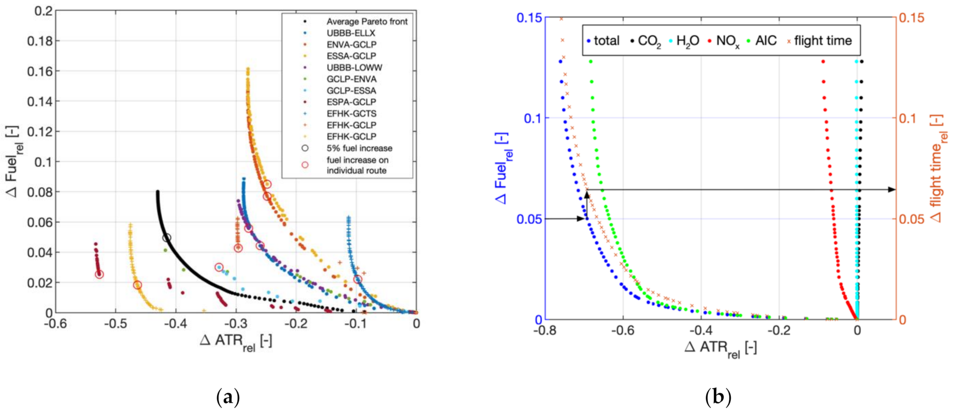
Figure 7a shows the individual Pareto fronts of the top 10 routes (colored) of the traffic scenario in terms of available seat kilometers as well as the resulting average Pareto front (black curve). The black circle indicates the +5% fuel burn point on the average Pareto front, which corresponds to a total climate impact reduction of about 42% for these routes. The red circles highlight the points that are chosen on each route’s Pareto front in order to achieve an overall +5% fuel burn increase while minimizing the total climate impact. Depending on the shape and slope of each individual Pareto front, climate impact mitigation and additional fuel burn may vary strongly between the routes. Here, for the top 10 routes, fuel burn increases between 1.9% (yellow crosses) and 8.5% (yellow dots), which lead to an average increase of 5% fuel burn are related with climate impact reductions between 10% (blue crosses) and 53% (dark red dots) on the individual routes.
Moreover, Figure 7b shows the average Pareto front for the top 2000 routes. A maximum climate impact reduction of about 76% can be achieved if a fuel penalty of 12.8% was accepted. Higher climate impact mitigation efficiencies (climate impact reduction per fuel increase) are obtained at low fuel penalties; e.g., a fuel penalty of 0.75% may already lead to a climate impact reduction of about 50%. The individual contribution of the species indicates that the climate impact reduction for the investigated weather pattern is dominated by the reduction of the contrail climate impact (green dots) followed by the reduction of the climate impact of NOx (red dots). Changes of the climate impact contributions of CO2 (black dots) and H2O (cyan dots) only have minor impacts on the overall Pareto front (blue dots). However, for this study, a weather situation with high contrail formation probabilities over Central Europe has been chosen (see Figure 1c and Figure 3b). Consequently, mitigation potentials and efficiencies may look very different for other weather situations and regions of the world. Figure 7b also shows that a reduction of the climate impact not only leads to higher fuel consumption but also to increased flight times (orange crosses). Additional fuel burn and flight time are correlated almost linearly. However, the flight time increase tends to be always 1–2% higher than the fuel burn increase; e.g., a fuel increase of 5% is related with a flight time increase of 6.4% (see black arrows).
Figure 8 shows the cumulative climate impact reduction as a function of the number of changed routes for a fuel penalty of 1% (a), 2% (b), and 12.8% (c). The routes have been sorted according to their absolute climate impact reduction. At a fuel penalty of 1%, which is related to a climate impact reduction of approximately 53% (see Figure 7b and Figure 8a), the adaption of only 500 of the total 2000 routes would already yield about 85% of the full potential, resulting in a total climate impact reduction of 45%. This effect slightly decreases for increasing fuel penalties: at 12.8% fuel penalty, 500 routes are related with about 75% of the overall potential and hence a climate impact reduction in the order of 55% (see Figure 8c). Since the slope of the individual contribution of the climate impact of contrails tends toward zero after about 1000 changed routes in all three cases (green curve), for this particular weather situation, it can be concluded that routes, which allow for the avoidance of areas where persistent contrails may form, are often characterized by high climate impact mitigation potentials and hence should be changed first.
Based on the average Pareto front of the top 2000 routes and the underlying individual Pareto fronts, the frequency distributions of different parameters are shown in Figure 9 for overall fuel penalties of 1% (blue bars), 2% (orange bars), 5% (yellow bars), and 12.8% (purple bars). The frequency distribution of the relative fuel increase as illustrated in Figure 9a shows a sharp peak at low fuel penalty levels for the 1% fuel increase case (blue bars). On more than 50% of the routes, the fuel penalty is below 0.15%, and on more than 78% of the routes, it is below 2%. However, for growing fuel increases, the spread of the frequency distribution becomes wider. For an overall fuel penalty of 12.8% (purple bars), on about 68% of the routes, fuel increase values between 5% and 10% occur. Additionally, on 8.7% of the routes, fuel increase values greater than 15% are observed.
Figure 9b shows the frequency distribution of the relative climate impact reduction. As expected, the climate impact is moving toward reduced values for increasing fuel penalties. The distributions show peak values at climate impact reductions of 1% (1% fuel increase), 9% (2% fuel increase), 13% (5% fuel increase), and 19% (12.8% fuel increase). However, for all investigated fuel penalties, between 36.7% (1% fuel increase) and 46.5% (12.8% fuel increase) of the routes show climate impact reductions that are larger than 40% and hence enable the large overall climate impact reductions of up to 76% as identified in Figure 7b. An overall cooling effect caused by flights through cooling contrail areas (see Figure 1c) has been observed on between 1.8% (1% fuel increase) and 7.6% (12.8% fuel increase) of the routes. The distribution of the mean altitude change compared to the minimum fuel trajectory is illustrated in Figure 9c. For increasing fuel penalties, the mean altitude is decreasing and shows peak values at altitude reductions of 90 m (1% fuel increase), 350 m (2% fuel increase), 590 m (5% fuel increase) and 1880 m (12.8% fuel increase). Mean altitude reductions larger than 3000 m are only observed in very few cases. The frequency distribution of the relative ground distance increase compared to the minimum fuel solution is depicted in Figure 9d. The distributions are characterized by a strong peak around zero, and more than 90% of the routes show ground distance changes below ±1% for all analyzed fuel penalties. Consequently, for the investigated weather situation and route network, the climate impact reduction is mainly obtained by flight altitude reductions and not by lateral rerouting around climate sensitive areas. Nevertheless, also large ground distance increases over 3% have been observed on 0.75% (1% fuel increase), 2% (2% fuel increase), 4.3% (5% fuel increase), and 7.5% (12.8% fuel increase) of the routes. However, at low fuel penalties and related high climate impact mitigation efficiencies (see Figure 7b), they only play a minor role.

4. Discussion

Within this study, the climate impact mitigation potential of intra-European air traffic is estimated for a one-day case study. Assuming a free-route airspace, aircraft trajectories are optimized with regard to climate impact by avoiding regions in which the atmosphere shows a high climate impact sensitivity with regard to non-CO2 emissions. Climate impact sensitivities are determined based on algorithmic climate change functions measuring the climate impact per unit emission based on meteorological parameters obtained from weather forecasts.
The results of the top 2000 routes (in terms of available seat kilometers) show a maximum climate impact mitigation potential of up to 76% and are related to an additional fuel burn of about 12.8% compared to the minimum fuel solution. However, the climate impact mitigation efficiency (reduction of climate impact per fuel penalty) is higher for lower fuel penalties: a climate impact reduction of 50% can already be achieved with only 0.75% of additional fuel burn on average. However, climate impact mitigation potentials and fuel penalties may vary strongly for different routes and weather situations. Since a case study day with high persistent contrail formation probability was chosen, the climate impact reduction is strongly dominated by the reduction of the contrail impact. However, also, the reduction of the climate impact caused by NOx has been identified to play an important role. Therefore, this study highlights that there is a high relevance of considering non-CO2 emissions when regulating the aviation sector. In order to further investigate these findings, in the following studies, different weather situations will be evaluated with regard to potential climate impact savings and the impact of individual species.
The results of this study have also shown that a large fraction of the overall climate impact mitigation potential between 75% and 85% can already be achieved with the modification of only approximately 25% of the routes with particularly high climate impact reduction potential. Additionally, it was found that the climate impact reductions—especially for low fuel penalties, which are related with high climate impact mitigation efficiencies—are essentially obtained by flying lower and not by rerouting around climate sensitive areas laterally. Therefore, these results indicate a large potential for an efficient implementation of climate-optimized trajectories and hence should be explored in future studies also considering air space capacity constraints and a structured air space. However, compared to other climate impact mitigation measures that focus on the reduction of CO2 emissions and hence fuel burn only, airline operators have to cope with additional fuel burn as well as flight time and therefore costs that may not be accepted without further incentives. In addition, since the climate impact prediction as well as weather forecasts are afflicted with uncertainties, the necessity of considering these effects has been identified. Therefore, future research will focus on robust trajectories taking into account uncertainties and different climate impact metrics [26].

Author Contributions

Conceptualization, all; methodology, B.L.; validation, F.Y. and V.G.; investigation, B.L. S.M.; writing—original draft preparation, B.L. and F.L.; writing—review and editing, all; visualization, B.L.; supervision, F.L.; project administration, S.M. All authors have read and agreed to the published version of the manuscript.

Funding

This research was funded by SESAR Joint Undertaking grant number 699395 (ATM4E) and grant number 891317 (FlyATM4E) under the European Union’s Horizon 2020 research and innovation programme. The funders had no role in the design of the study; in the collection, analyses, or interpretation of data; in the writing of the manuscript, or in the decision to publish the results.

Data Availability Statement

The data presented in this study are available on reasonable request from the corresponding author.

Acknowledgments

Work in this article was supported by the DLR project Eco2Fly (2018–2022). The Base of Aircraft Data (BADA) aircraft performance models and the access to the Demand Data Repository were kindly provided by EUROCONTROL. Additionally, we thank Keith P. Shine and Emma Klingaman for their support.

Conflicts of Interest

The authors declare no conflict of interest.

Abbreviations

The following abbreviations are used in this manuscript:
aCCFAlgorithmic Climate Change Function
ATCAir Traffic Control
ATM4EAir Traffic Management for Environment
ATRAverage Temperature Response
BADABase of Aircraft Data
CCFClimate Change Function
DDRDemand Data Repository
DLRDeutsches Zentrum für Luft- und Raumfahrt (German Aerospace Center)
ECACEuropean Civil Aviation Conference
ECMWFEuropean Centre for Medium-Range Weather Forecasts
Eco2Fly
ERA
Ecological and Economical Flying
ECMWF Reanalysis
EUEuropean Union
REACT4CReducing Emissions from Aviation by Changing Trajectories for the benefit of Climate
TOMTrajectory Optimization Module

References

  1. Lee, D.S. Aviation and global climate change in the 21st century. Atmos. Environ. 2009, 43, 352020133537. [Google Scholar] [CrossRef] [PubMed] [Green Version]
  2. Schumann, U.; Graf, K.; Mannstein, H. Potential to reduce the climate impact of aviation by flight level changes. In Proceedings of the 3rd AIAA Atmospheric Space Environments Conference, Honululu, HI, USA, 27–30 June 2011. [Google Scholar]
  3. Sridhar, B.; Chen, N.Y.; Ng, H.K. Energy efficient contrail mitigation strategies for reducing the environmental impact of aviation. In Proceedings of the 10th USA/Europe Air Traffic Management Research and Development Seminar, Chicago, IL, USA, 10–13 June 2013. [Google Scholar]
  4. Hartjes, S.; Hendriks, T.; Visser, H.G. Contrail mitigation through 3D aircraft trajectory optimization. In Proceedings of the 16th AIAA Aviation Technology, Integration, and Operations Conference, Washington, DC, USA, 13–17 June 2016. [Google Scholar] [CrossRef]
  5. Zou, B.; Buxi, G.S.; Hansen, M. Optimal 4-D aircraft trajectories in a Contrail-sensitive Environment. Netw. Spat. Econ. 2016, 16, 415–446. [Google Scholar] [CrossRef]
  6. Matthes, S. Climate-optimised flight planning–REACT4C. In Innovation for a Sustainable Aviation in a Global Environment, Proceedings of the Sixth European Aeronautics Days 2011, Madrid, Spain, 30 March--1 April 2011; IOS Press & European Union: Madrid, Spain, 2012; ISBN 978-92-79-22968-8. [Google Scholar]
  7. Grewe, V.; Frömming, C.; Matthes, S.; Brinkop, S.; Ponater, M.; Dietmüller, S.; Jöckel, P.; Garny, H.; Tsati, E.; Dahlmann, K.; et al. Aircraft routing with minimal climate impact: The REACT4C climate cost function modelling approach (V1.0). Geosci. Model Dev. 2014, 7, 175–201. [Google Scholar] [CrossRef] [Green Version]
  8. Irvine, E.A.; Hoskins, B.J.; Shine, K.P.; Lunnon, R.W.; Frömming, C. Characterizing North Atlantic weather patterns for climate-optimal aircraft routing. Meteorol. Appl. 2013, 20, 80–93. [Google Scholar] [CrossRef] [Green Version]
  9. Grewe, V.; Champougny, T.; Matthes, S.; Frömming, C.; Brinkop, S.; Søvde, O.; Irvine, E.A.; Halscheidt, L. Reduction of the air traffic’s contribution to climate change: A REACT4C case study. Atmos. Environ. 2014, 94, 616–625. [Google Scholar] [CrossRef] [Green Version]
  10. Grewe, V.; Matthes, S.; Frömming, C.; Brinkop, S.; Jöckel, P.; Gierens, K.; Champougny, T.; Fuglestvedt, J.; Haslerud, A.; Irvine, E.A.; et al. Feasibility of climate-optimized air traffic routing for trans-atlantic flights. Environ. Res. Lett. 2017, 12. [Google Scholar] [CrossRef]
  11. Lührs, B.; Niklaß, M.; Frömming, C.; Grewe, V.; Gollnick, V. Cost-Benefit Assessment of Climate and Weather Optimized Trajectories for different North Atlantic Weather Patterns. In Proceedings of the 31st Congress of the International Council of the Aeronautical Sciences (ICAS), Belo Horizonte, Brazil, 9–14 September 2018. [Google Scholar]
  12. Matthes, S.; Grewe, V.; Dahlmann, K.; Frömming, C.; Irvine, E.; Lim, L.; Linke, F.; Lührs, B.; Owen, B.; Shine, K.P.; et al. A Concept for Multi-Criteria Environmental Assessment of Aircraft Trajectories. Aerospace 2017, 4, 42. [Google Scholar] [CrossRef] [Green Version]
  13. Frömming, C.; Grewe, V.; Brinkop, S.; Jöckel, P.; Haslerud, A.S.; Rosanka, S.; van Manen, J.; Matthes, S. Influence of the actual weather situation on non-CO2 aviation climate effects: The REACT4C Climate Change Functions. Atmos. Chem. Phys. Discuss. 2020. under review. [Google Scholar] [CrossRef]
  14. Van Manen, J.; Grewe, V. Algorithmic climate change functions for the use in eco-efficient flight planning. Trans. Res. Part D Trans. Environ. 2019, 67, 388–405. [Google Scholar] [CrossRef]
  15. Yin, F.; Grewe, V.; van Manen, J.; Matthes, S.; Yamashita, H.; Irvine, E.A.; Shine, K.P.; Lührs, B.; Linke, F. Verification of the ozone algorithmic climate change functions for predicting the short-term NOx effects from aviation en-route. In Proceedings of the 8th International Conference on Air Transportation (ICRAT), Barcelona, Spain, 26–29 June 2018. [Google Scholar]
  16. Yin, F.; Grewe, V.; Matthes, S.; Yamashita, H.; Irvine, E.A.; Shine, K.P.; Lührs, B.; Linke, F. Predicting the climate impact of aviation for en-route emissions: The algorithmic climate change function sub model ACCF 1.0 of EMAC 2.53. Geosci. Model Dev. Discuss. 2020. in preparation. [Google Scholar]
  17. Yamashita, H.; Yin, F.; Grewe, V.; Jöckel, P.; Matthes, S.; Kern, B.; Dahlmann, K.; Frömming, C. Various aircraft routing options for air traffic simulation in the chemistry-climate model EMAC 2.53: AirTraf 2.0. Geosci. Model Dev. Discuss. 2020. under review. [Google Scholar] [CrossRef]
  18. Appleman, H. The Formation of Exhaust Condensation Trails by Jet Aircraft. Bull. Am. Meteorol. Soc. 1953, 34, 14–20. [Google Scholar] [CrossRef] [Green Version]
  19. Lührs, B.; Niklaß, M.; Frömming, C.; Grewe, V.; Gollnick, V. Cost-Benefit Assessment of 2D- and 3D Climate and Weather Optimized Trajectories. In Proceedings of the 16th AIAA Aviation Technology, Integration, and Operations Conference, Washington, DC, USA, 13–17 June 2016. [Google Scholar]
  20. Patterson, M.A.; Rao, A.V. GPOPS-II: A MATLAB Software for Solving Multiple-Phase Optimal Control Problems Using hp-Adaptive Gaussian Quadrature Collocation Methods and Sparse Nonlinear Programming. ACM Trans. Math. Softw. 2014, 41, 1–37. [Google Scholar] [CrossRef] [Green Version]
  21. Wächter, A.; Biegler, L.T. On the implementation of an interior-point filter line-search algorithm for large-scale nonlinear programming. Math. Progr. 2006, 106, 25–57. [Google Scholar] [CrossRef]
  22. Nuic, A.; Mouillet, V. User Manual for the Base of Aircraft Data (BADA) Family 4; ECC Technical/Scientific Report No. 12/11/22-58; Eurocontrol: Brussels, Belgium, 2012. [Google Scholar]
  23. DuBois, D.; Paynter, G. ‘Fuel Flow Method 2’ for Estimating Aircraft Emissions. SAE Trans. 2006, 115, 1–14. [Google Scholar]
  24. Jelinek, F. Advanced Emission Model (AEM3) v1.5-Validation Report; EEC Report EEC/SEE/2004/004; Eurocontrol: Brussels, Belgium, 2004. [Google Scholar]
  25. Dee, D.P. The ERA-Interim reanalysis: Configuration and performance of the data assimilation system. Quart. J. R. Meteorol. Soc. 2011, 137, 553–597. [Google Scholar] [CrossRef]
  26. Matthes, S.; Lührs, B.; Dahlmann, K.; Linke, F.; Grewe, V.; Yin, F.; Shine, K.P. Climate-Optimized Trajectories and Robust Mitigation Potential: Flying ATM4E. Aerospace 2020, 7, 156. [Google Scholar] [CrossRef]
Figure 1. Algorithmic climate change functions for H2O (a), NOx (b), and contrails (c) on 18 December 2015, 6.00 p.m. UTC as function of latitude and longitude on flight level 390.
Aerospace 08 00050 g001
Figure 2. Algorithmic climate change functions for H2O (a), NOx (b), and contrails (c) on 18 December 2015, 6.00 p.m. UTC as function of longitude and altitude at 48° N.
Aerospace 08 00050 g002
Figure 3. Geopotential height (black contours), wind situation (arrows), and regions of potential contrail formation (blue) over Europe on 18 December 2015, 12.00 pm UTC based on European Centre for Medium-Range Weather Forecasts (ECMWF) ERA-Interim re-analysis data on pressure levels 250 hPa (a) and 200 hPa (b).
Aerospace 08 00050 g003
Figure 4. Cumulative CO2 emission distributions of the chosen reference traffic on 18 December 2015, between 11.30 a.m. and 12.00 p.m. UTC as function of latitude and longitude (top left), altitude and latitude (top right) as well as altitude and longitude (bottom). Black dots indicate aircraft positions at 12.00 pm UTC.
Aerospace 08 00050 g004
Figure 5. Optimized trajectories for the route Luleå-Gran Canaria. The lateral path of the minimum fuel trajectory (black) is illustrated including the wind situation (a) and the total climate sensitivity (b) at an average altitude of 10,686 m. The orthodrome is depicted in blue. The lateral path of the minimum climate impact trajectory is not shown separately, since only minor deviations from the minimum fuel trajectory occur. Altitude profiles along the cross section of the lateral path are shown for the minimum fuel case (c), (d) and the minimum climate impact case (e), (f) as a function of the relative flight time t/tf. The wind situation for the vertical trajectories is indicated as ratio between ground speed v GS and true airspeed v TAS . Values greater than one indicate tailwind areas, values smaller than one indicate headwind areas.
Aerospace 08 00050 g005
Figure 6. Pareto fronts for Baku–Luxembourg (a), Luleå–Gran Canaria (b), and Helsinki–Gran Canaria (c). The colored dots indicate the individual contribution of CO2 (black), H2O (cyan), NOx (red), and contrails (green) to the overall climate impact reduction (blue) for a given fuel increase. Results are expressed relative to the fuel burn and the total climate impact of the minimum fuel case.
Aerospace 08 00050 g006
Figure 7. Top 10 single route Pareto fronts and corresponding average Pareto front (a) and average Pareto front (b) for the top 2000 routes with individual contribution of the species CO2 (black), H2O (cyan), NOx (red), and contrails (green) to the overall climate impact reduction (blue) for a given fuel increase. Results are expressed relative to the minimum fuel case.
Aerospace 08 00050 g007
Figure 8. Cumulative average temperature response (ATR) reduction as a function of the number of changed routes for 1% (a), 2% (b), and 12.8% (c) increase in fuel burn for the top 2000 routes. Individual contributions to the total ATR reduction (blue) are shown for CO2 (black), H2O (cyan), NOx (red), and contrails (green).
Aerospace 08 00050 g008
Figure 9. Frequency distributions of the relative fuel increase (a), the relative ATR reduction (b), the mean altitude change (c), and the relative ground distance increase (d) compared to the minimum fuel trajectory based on the top 2000 routes for 1% (blue), 2% (orange), 5% (yellow), and 12.8% (purple) overall fuel penalty.
Aerospace 08 00050 g009
Publisher’s Note: MDPI stays neutral with regard to jurisdictional claims in published maps and institutional affiliations.