Exemplification of Detecting Gas Turbine Blade Structure Defects Using the X-ray Computed Tomography Method
Abstract
:1. Introduction
- defective manufacturing;
- operating process;
- faulty repair.
- an ultrasonic tomographic imaging technique [14];
- quality analyses of dissimilar materials joint [15];
- laser cladding parameters optimization in blisk-type part manufacturing [16];
- FIB–SEM electron tomography to characterize the microstructure of super alloy [17]; and
- polychromatic X-ray radiography with a single image [18].
1.1. CT—Requirements and Limitations
1.2. CT—Examples of Use
1.3. Purpose of the Work
2. Materials and Methods
2.1. Materials
2.2. Methods
2.2.1. Test Analysis Using the XCT Method
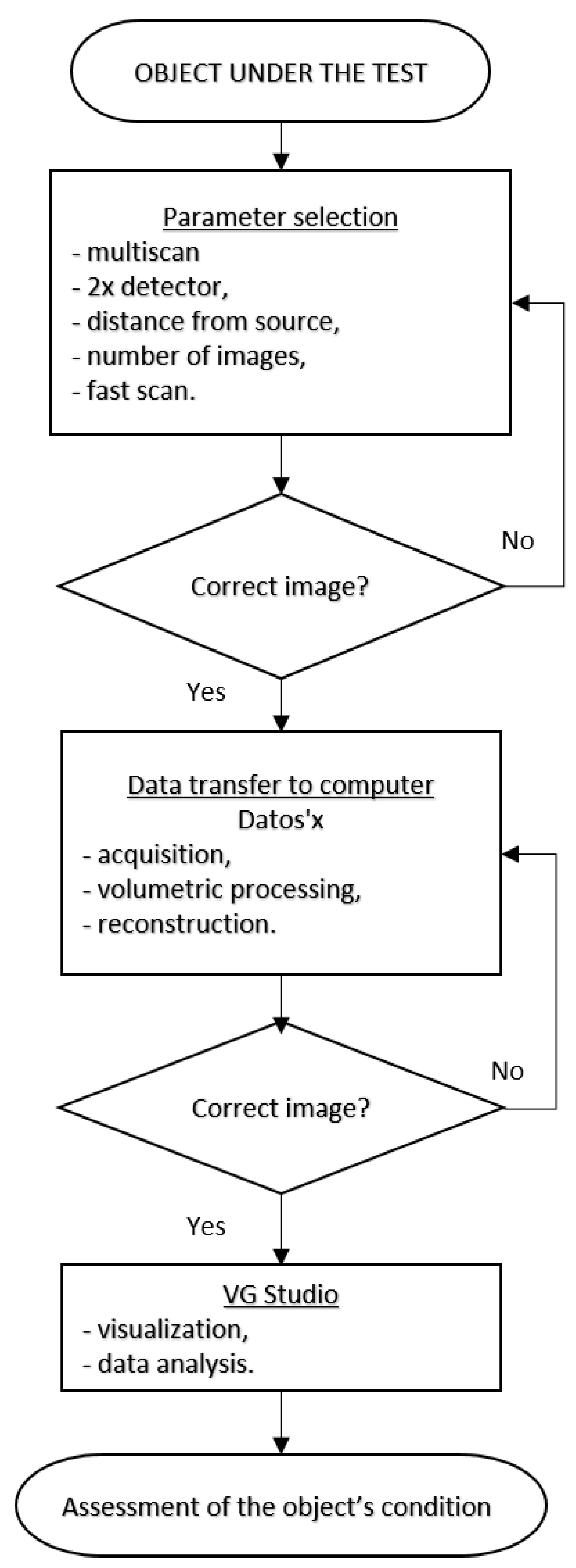
2.2.2. Test Methodology of Turbine Blades
- preliminary study; and
- main research.
- it does not contain artifacts—apparent defects that in reality do not occur in the object; and
- the defects have clear contours that make it possible to determine their shape and dimensions.
2.2.3. The Testing Device
- General parameters of V/TOME/X M 300 system are as follows:
- Connection parameters: Voltage 230 V, frequency 50/60 Hz, max. power consumption 2300 VA;
- Power parameters: high voltage 10–300 kV, current of the X-ray tube 5–3000 µA;
- Thickness of the beam exit window 0.5 mm, thickness of the useful beam approx. 25°;
- Recognizability of details <1 µm; and
- X-ray tube radiation parameters: high voltage 10–180 kV, current of X-ray tube by 15 isowatts 5–880 µA, beam cone approx. 180°.
- Software:
- X-ray control system—xs/control; and
- for image analysis—quality/assurances.
2.2.4. Measurement Functions and Software
- standard geometry of dimensions;
- comparing the results with CAD models;
- flaw detection; and
- reverse engineering.
3. Results
3.1. The Impact of the Important Experiment Parameters on the Quality of Test Results
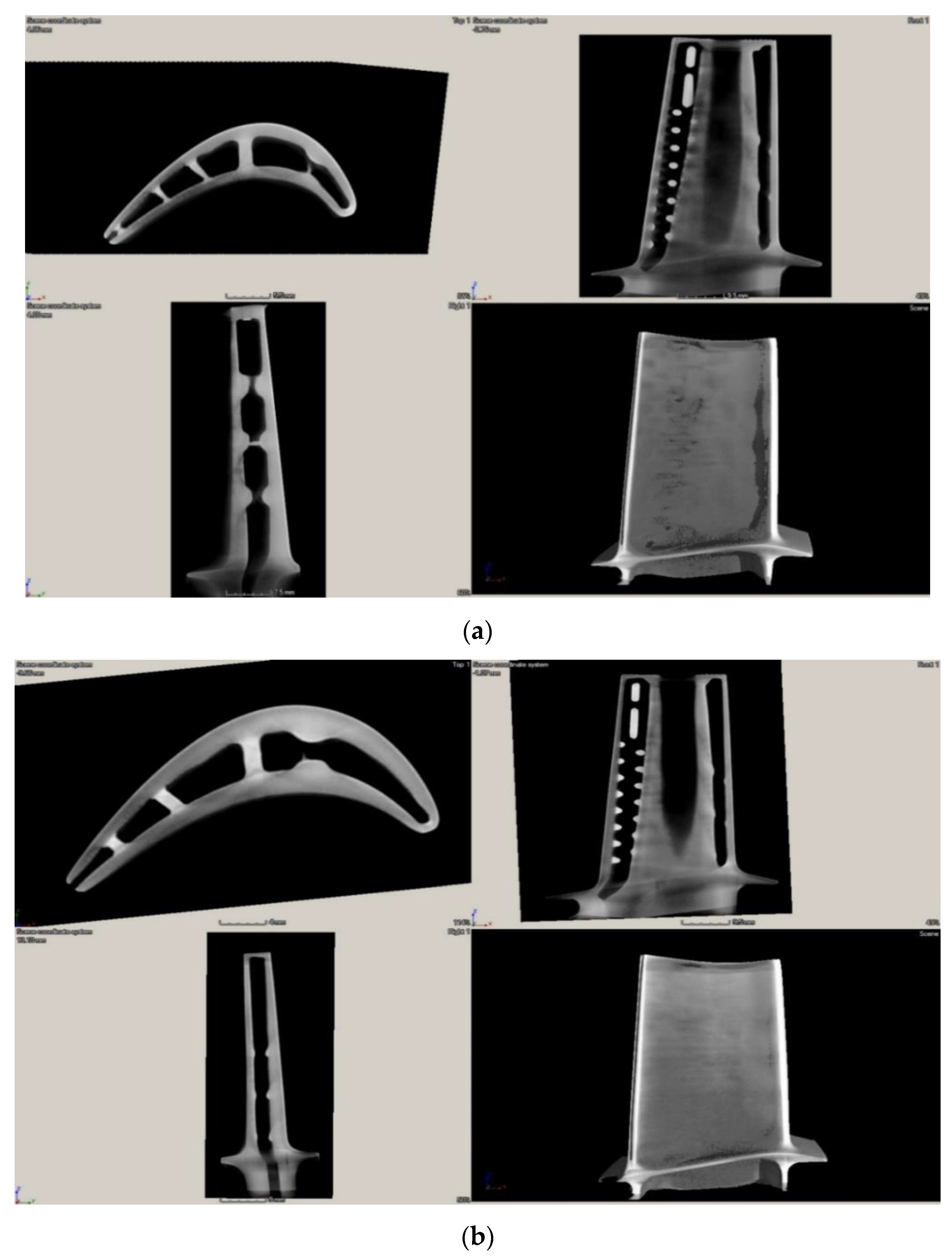
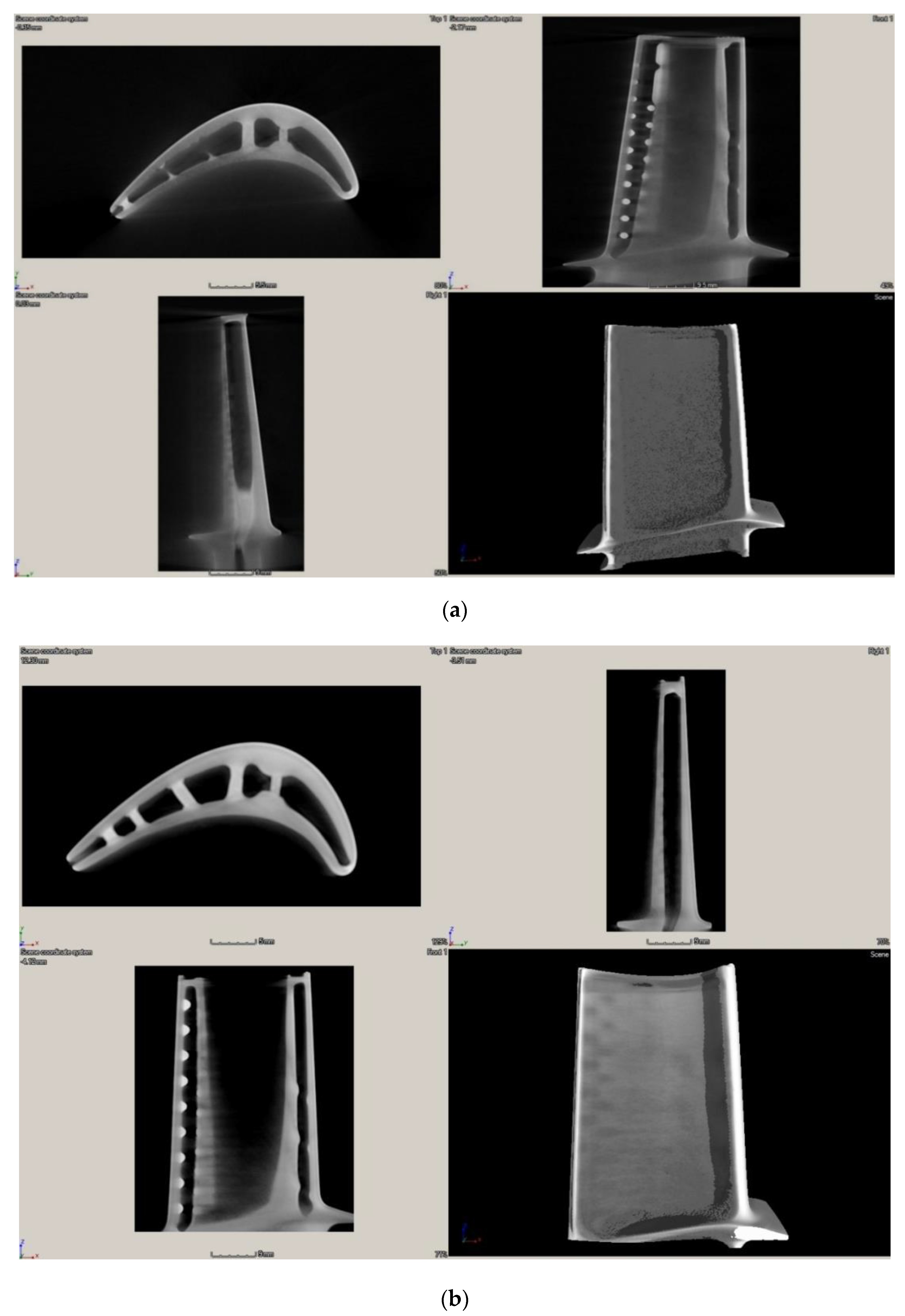
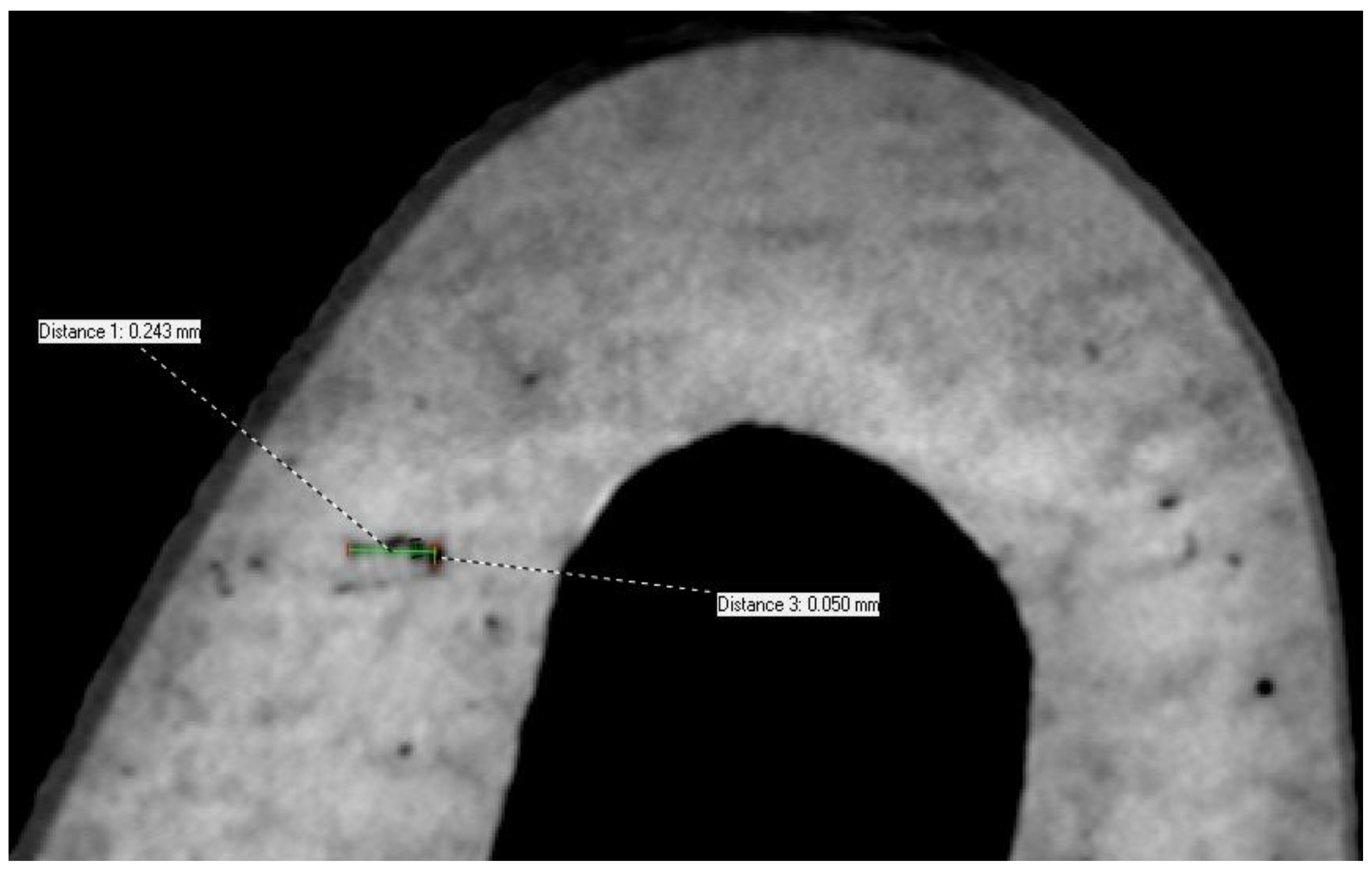
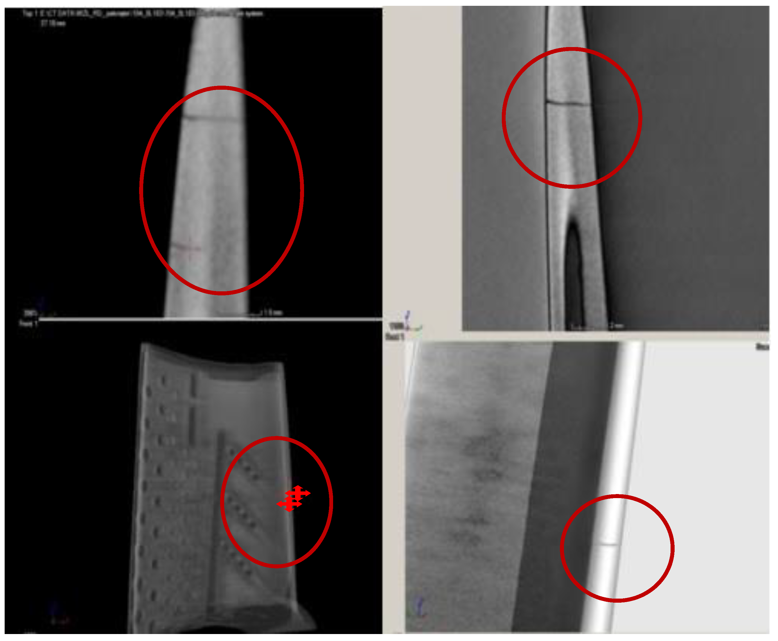
3.2. Detecting Defects in Gas Turbine Blades
4. Discussion on Test Results
- incorrect setting of CT system operation parameters—X-ray intensity, Equation (1), X-ray linear attenuation coefficient, Equation (2);
- incorrect number of images;
- too low power of X-ray tube—initial radiation intensity, Equation (1);
- incorrect background calibration;
- incorrect fitting of the component on the rotary table;
- incorrect component positioning;
- too big dimensions of the tested object, as a result of which less than the test area is contained in the X-ray cone beam;
- insufficient image resolution resulting from the incorrect distance of the component from the radiation source; and
- too high power of the X-ray tube as compared to the voxel size.
- determining the edge boundary based on the shades of grey;
- averaging the area based on filters, e.g., Gauss;
- incorrect optimization of calibration images; and
- determining the incorrect axis using the sector scan.
5. Conclusions
Author Contributions
Funding
Institutional Review Board Statement
Informed Consent Statement
Data Availability Statement
Conflicts of Interest
References
- Aust, J.; Pons, D. Taxonomy of Gas Turbine Blade Defects. Aerospace 2019, 6, 58. [Google Scholar] [CrossRef] [Green Version]
- Błachnio, J.; Bogdan, M.; Zasada, D. Increased temperature impact on durability of gas turbine blades. Eksploat. I Niezawodn. Maint. Reliab. 2017, 19, 48–53. [Google Scholar] [CrossRef]
- Błachnio, J.; Kułaszka, A.; Perczyński, J. The impact of unevenness and instability of flue gas temperature on the technical condition of gas turbine blades. J. Kones Powertrain Transport. 2018, 25. [Google Scholar] [CrossRef]
- Błachnio, J.; Kułaszka, A.; Zasada, D. Degradation of the gas turbine blade coating and its influence on the microstructure state of the superalloy. J. Kones 2015, 22. [Google Scholar] [CrossRef]
- Aust, J.; Shankland, S.; Pons, D.; Mukundan, R.; Mitrovic, A. Automated Defect Detection and Decision-Support in Gas Turbine Blade Inspection. Aerospace 2021, 8, 30. [Google Scholar] [CrossRef]
- Bogdan, M.; Błachnio, J.; Kułaszka, A.; Derlatka, M. Assessing the condition of gas turbine rotor blades with the optoelectronic and thermographic methods. Metals 2019, 9, 31. [Google Scholar] [CrossRef] [Green Version]
- Błachnio, J.; Spychała, J.; Chalimoniuk, M. Non-destructive computed tomography method for assessing the condition of gas turbine blades. In Problems of Aeronautical Research and Operation, Wyd; ITWL: Warszawa, Poland, 2012; Volume 8, pp. 1–10. [Google Scholar]
- Fentaye, A.D.; Baheta, A.T.; Gilani, S.I.; Kyprianidis, K.G. A Review on Gas Turbine Gas-Path Diagnostics: State-of-the-Art Methods, Challenges and Opportunities. Aerospace 2019, 6, 83. [Google Scholar] [CrossRef] [Green Version]
- Borowczyk, H.; Błachnio, J. Database of Expert Diagnostic System in the Field of Turbine Blades Non-Destructive Testing. J. Kones 2018, 25, 25. [Google Scholar] [CrossRef]
- Database of Air Force Institute of Technology Warszawa; (AFIT Intranet—for AFIT Staff only); AFIT Intranet: Warszawa, Poland, 2020.
- Bogdan, M.; Derlatka, M.; Błachnio, J. Concept of Computer-Aided Assessment of the Technical Condition of Operated Gas Turbine Vanes. Pol. Marit. Res. 2018, 25, 9. [Google Scholar] [CrossRef] [Green Version]
- RD-33 Aircraft Engine Technical Operation Manual 088.00.1700RE, Part 2, Air Force Headquarters: Warsaw, Poland, 2001.
- Przysowa, R.; Chalimoniuk, M.; Grzelka-Gajek, D.; Shakalo, R.; Karpenko, A. CT Inspection of Cooled Turbine Blades. J. Konbin 2020, 50, 307–331. [Google Scholar] [CrossRef]
- Ratassepp, M.; Rao, J.; Fan, Z. Quantitative imaging of Young’s modulus in plates using guided wave tomography. NDT E Int. 2018, 94, 22–30. [Google Scholar] [CrossRef]
- Urbikain, G.; Perez, J.M.; López de Lacalle, L.N.; Andueza, A. Combination of friction drilling and form tapping processes on dissimilar materials for making nutless joints. Proc. Inst. Mech. Eng. Part. B J. Eng. Manuf. 2018, 232, 1007–1020. [Google Scholar] [CrossRef]
- Calleja, A.; Tabernero, I.; Ealo, J.A.; Campa, F.J.; Lamikiz, A.; de Lacalle, L.N.L. Feed rate calculation algorithm for the homogeneous material deposition of blisk blades by 5-axis laser cladding. Int. J. Adv. Manuf. Technol. 2014, 74, 1219–1228. [Google Scholar] [CrossRef]
- Ziętara, M.; Kruk, A.; Gruszczyński, A.; Czyrska-Filemonowicz, A. FIB–SEM tomography of 4th generation PWA 1497 superalloy. Mater. Charact. 2014, 87, 143–148. [Google Scholar] [CrossRef]
- Rometsch, P.A.; Pelliccia, D.; Tomus, D.; Wu, X. Evaluation of polychromatic X-ray radiography defect detection limits in a sample fabricated from Hastelloy X by selective laser melting. NDT E Int. 2014, 62, 184–192. [Google Scholar] [CrossRef]
- Heinzl, C.; Kastner, J.; Amirkhamov, A.; Gröller, E.; Gusenbauer, C. Optimal specimen placement in cone beam X-ray computed tomography. NDT E Int. 2012, 50, 42–49. [Google Scholar] [CrossRef]
- Brierley, N.; Nye, B.; McGuinness, J. Mapping the Spatial Performance Variability of an X-ray Computed Tomography Inspection. NDT E Int. 2019, 107. [Google Scholar] [CrossRef]
- Jones, G.A.; Huthwaite, P. Limited view X-ray tomography for dimensional measurements. NDT E Int. 2018, 93, 98–109. [Google Scholar] [CrossRef]
- Prade, F.; Schaff, F.; Senck, S.; Meyer, P.; Mohr, J.; Kastner, J.; Pfeiffer, F. Nondestructive characterization of fiber orientation in short fiber reinforced polymer composites with X-ray vector radiography. NDT E Int. 2017, 86, 65–72. [Google Scholar] [CrossRef]
- De Pascalis, F.; Nacucchi, M.; Scatto, M.; Albertoni, R. Quantitative characterisation of low-density, high performance polymeric foams using high resolution X-ray computed tomography and laser confocal microscopy. NDT E Int. 2016, 83, 123–133. [Google Scholar] [CrossRef]
- Ziółkowski, G.; Chlebus, E.; Szymczyk, P.; Kurzac, J. Application of X-ray CT method for discontinuity and porosity detection in 316L stainless steel parts produced with SLM technology. Arch. Civ. Mech. Eng. 2014, 14, 608–614. [Google Scholar] [CrossRef]
- Zheng, S.; Vanderstelt, J.; McDermid, J.R.; Kish, J.R. Non-destructive investigation of aluminum alloy hemmed joints using neutron radiography and X-ray computed tomography. NDT E Int. 2017, 91, 32–35. [Google Scholar] [CrossRef]
- Kolkoori, S.; Wrobel, N.; Zscherpel, U.; Ewert, U. A new X-ray backscatter imaging technique for non-destructive testing of aerospace materials. NDT E Int. 2015, 70, 41–52. [Google Scholar] [CrossRef]
- Reddy, M.V.; Lukose, S.N.; Subramanian, M.P.; Rao, G.V.S.; Muralidhar, C.; Balasubramaniam, K. Industrial computed tomography system for aerospace applications: Development and characterisation. Insight Non-Destr. Test. Cond. Monit. 2011, 53, 307–311. [Google Scholar] [CrossRef]
- Muralidhar, C.; Lukose, S.; Subramanian, M. Evaluation of turbine blades using computed tomography. In Proceedings of the National Seminar on Non-Destructive Evaluation, Hyderabad, India, 1–4 December 2006. [Google Scholar]
- Asadizanjani, N. 3D Imaging and Investigation of Failure and Deformation in Thermal Barrier Coatings Using Computed X-ray Tomography. Ph.D. Thesis, University of Connecticut, Mansfield, CT, USA, 2014. [Google Scholar]
- Chalimoniuk, M.; Szczepanik, R.; Błachnio, J. The rate of decohesion of a gas turbine blade as assessed with the X-ray computed tomography (CT). J. Kones 2013, 20, 89–96. [Google Scholar]
- Kageyama, M.; Okajima, K.; Maesawa, M.; Nonoguchi, M.; Koike, T.; Noguchi, M.; Yamada, A.; Morita, E.; Kawase, S.; Kuribayashi, M.; et al. X-ray phase-imaging scanner with tiled bent gratings for large-field-of-view nondestructive testing. NDT E Int. 2019, 105, 19–24. [Google Scholar] [CrossRef]
- De Schryver, T.; Dhaene, J.; Dierick, M.; Boone, M.N.; Janssens, E.; Sijbers, J.; van Dael, M.; Verboven, P.; Nicolai, B.; Van Hoorebeke, L. In-line NDT with X-Ray CT combining sample rotation and translation. NDT E Int. 2016, 84, 89–98. [Google Scholar] [CrossRef] [Green Version]
- Datos|x Reconstruction. CT Data Optimisation and Reconstruction Software, Manual; GE Sensing & Inspection Technologies GmbH Phoenix|X-ray: Wunstorf, Germany, 2011; Electronic Document Created 2011.
- VGSTUDIO MAX, Version 2.2, Volume Graphics GmbH, Wieblinger Weg 92a, 69123 Heidelberg, Germany. (Version 2021). Available online: https://www.volumegraphics.com/en/products/vgstudio-max.html (accessed on 19 April 2021).
- VGMETROLOGY, Version 2.2, Volume Graphics GmbH, Wieblinger Weg 92a, 69123 Heidelberg, Germany. (Version 2021). Available online: https://www.volumegraphics.com/en/products/vgmetrology.html (accessed on 19 April 2021).




Publisher’s Note: MDPI stays neutral with regard to jurisdictional claims in published maps and institutional affiliations. |
© 2021 by the authors. Licensee MDPI, Basel, Switzerland. This article is an open access article distributed under the terms and conditions of the Creative Commons Attribution (CC BY) license (https://creativecommons.org/licenses/by/4.0/).
Share and Cite
Błachnio, J.; Chalimoniuk, M.; Kułaszka, A.; Borowczyk, H.; Zasada, D. Exemplification of Detecting Gas Turbine Blade Structure Defects Using the X-ray Computed Tomography Method. Aerospace 2021, 8, 119. https://doi.org/10.3390/aerospace8040119
Błachnio J, Chalimoniuk M, Kułaszka A, Borowczyk H, Zasada D. Exemplification of Detecting Gas Turbine Blade Structure Defects Using the X-ray Computed Tomography Method. Aerospace. 2021; 8(4):119. https://doi.org/10.3390/aerospace8040119
Chicago/Turabian StyleBłachnio, Józef, Marek Chalimoniuk, Artur Kułaszka, Henryk Borowczyk, and Dariusz Zasada. 2021. "Exemplification of Detecting Gas Turbine Blade Structure Defects Using the X-ray Computed Tomography Method" Aerospace 8, no. 4: 119. https://doi.org/10.3390/aerospace8040119
APA StyleBłachnio, J., Chalimoniuk, M., Kułaszka, A., Borowczyk, H., & Zasada, D. (2021). Exemplification of Detecting Gas Turbine Blade Structure Defects Using the X-ray Computed Tomography Method. Aerospace, 8(4), 119. https://doi.org/10.3390/aerospace8040119


