
Coupled Fluid–Solid Numerical Simulation for Flow Field Characteristics and Supporting Performance of Flexible Support Cylindrical Gas Film Seal

 ,
,
Abstract
:1. Introduction
2. Model
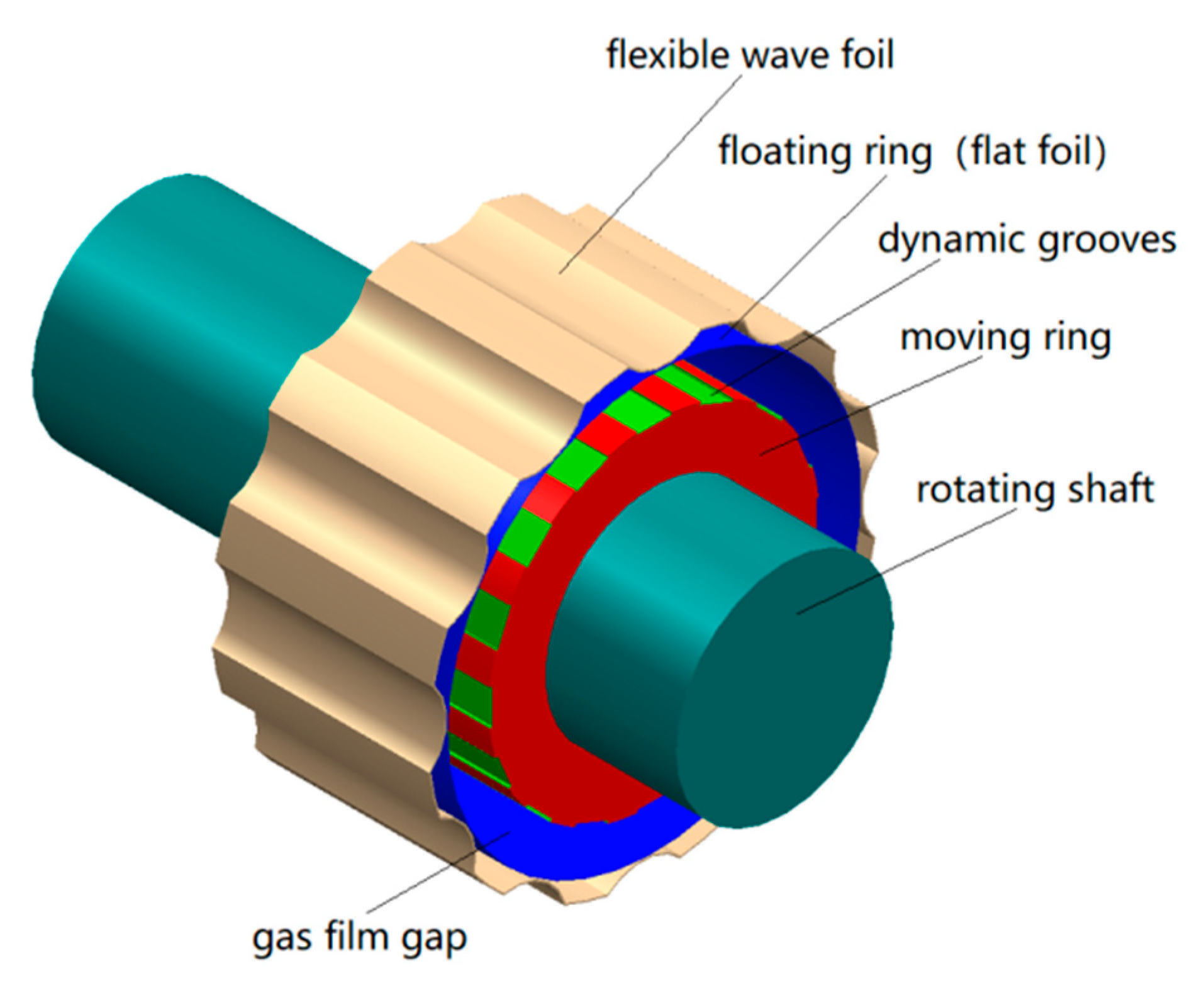
2.1. Physical Model
2.2. Mathematical Model
2.3. Calculation of Gas Film Steady Sealing Characteristic Parameters
2.3.1. Film Buoyancy Lift
2.3.2. Leakage
2.3.3. Gas Film Stiffness
3. Model Parameters
3.1. Parameters of Flexible Supporting Structure
3.2. Basic Assumptions
3.2.1. Basic Assumption of Flow Field
3.2.2. Basic Assumptions of Wave Foil Structure Bending
3.3. Modelling and Meshing
3.4. Boundary Conditions and Solver Setting
4. Analysis of Flow Field Characteristics
4.1. Effect of Operating Parameters on Sealing Ability
4.1.1. The Impacts of Rotational Speed
4.1.2. The Impact of Pressure Difference
4.2. Impacts of Structural Parameters on Sealing Performance
4.2.1. Impact of Eccentricity
4.2.2. Impact of Number of Grooves
4.2.3. Impact of Groove Depth
4.2.4. Impact of Groove Length
5. Fluid-Structure Coupling Analysis of Flexible Support Performance
5.1. Average Gas Film Thickness
5.2. Eccentricity
5.3. Number of Wave Foils
6. Conclusions
- (1)
- When the rotor speed increases, the sealing performance improves slightly. From the perspective of the sealing applicability, it shows that the sealing parameters used in this paper are suitable for working conditions with high rotational speed. Since the increase of pressure difference leads to increase of leakage, this counteracts the hydrodynamic effect. Therefore, although the gas film stiffness increases, the increase is relatively small.
- (2)
- As the eccentricity increases, the film thickness increases at the largest film gap but decreases at the minimum film gap. With the combined effects, the leakage increases significantly, the film buoyancy lift increases slightly, and the gas film stiffness decreases. As the number of grooves increases, the wedge and hydrodynamic effects are enhanced, the leakage and film buoyancy increase, and the film stiffness decrease continuously. When the groove depth increases, the wedge effect increases slightly, and the film stiffness increases significantly. When the groove length increases, the film buoyancy lift increases first and then decreases, the leakage increases, and the gas film stiffness decreases significantly.
- (3)
- As the average film thickness increases, the hydrodynamic effect declines and the force acting on the flexible support decreases, so the average equivalent stress of the flexible support also decreases. When the film thickness is bigger than 15 μm, the equivalent stress of the flexible support tends to be stable.
- (4)
- As the eccentricity increases, the wedge-shaped gap between the moving ring and floating ring becomes smaller, the hydrodynamic effect is enhanced, the force of gas film acting on the flexible support in the flow field increases, and the equivalent stress increases accordingly, when the eccentricity is bigger than 0.6, the equivalent stress stabilizes gradually.
- (5)
- As the number of wave foils increases, the effective resistance area of wave foils against the pressure of gas film becomes larger, so the deformation of wave foil and the average equivalent stress decrease. Therefore, if the number of wave foils is too big, the bearing capacity and ability to resist deformation of flexible support structure is strengthened, but the radial displacement of rotor cannot be buffered effectively. Therefore, the selection of the number of wave foils should consider both the support rigidity and the ability to buffer the radial displacement effectively.
7. Patents
Author Contributions
Funding
Institutional Review Board Statement
Informed Consent Statement
Data Availability Statement
Acknowledgments
Conflicts of Interest
References
- Shen, H.; Zheng, T.; Chen, Y. Improvement of aero-engine sealing technology. Gas Turbine Exp. Res. 2011, 4, 51–55. [Google Scholar]
- Steinetz, B.M.; Hendricks, R.C. Engine seal technology requirements to meet NASA’s Advanced Subsonic Technology program goals. J. Propuls. Power 1996, 12, 786–793. [Google Scholar] [CrossRef] [Green Version]
- Ma, G.; Sun, X.; Luo, X.; He, J. Numerical simulation analysis of steady-state properties of gas face and cylinder film seal. J. Beijing Univ. Aeronaut. Astronaut. 2014, 4, 439–443. [Google Scholar]
- Su, Z.; Liu, M. CFD numerical simulation of cylindrical gas film seal properties. Lubr. Eng. 2016, 9, 49–53. [Google Scholar]
- Ma, G.; Shen, X. Research progress and analysis of advanced gas film sealing technology. Aviat. Manuf. Technol. 2009, 3, 58–61. [Google Scholar]
- Chen, T.; Liu, M. Research progress and development trend of cylindrical gas film seal. New Technol. New Process 2014, 6, 78–81. [Google Scholar]
- Sun, J.; Liu, M.; Li, Y.; Su, Z.; Kang, Y. Analysis on steady fluid dynamics of cylindrical gas seal by CFD. Drain. Irrig. Mach. 2017, 11, 968–974. [Google Scholar]
- Sedy, J. A new self-aligning mechanism for the spiral-groove gas seal stability. Lubr. Eng. 1980, 36, 592–598. [Google Scholar]
- Song, L. Current development of dry gas seal used with large diameter shaft at home and abroad and application in china. Process Equip. Pip. 2016, 1, 39–42. [Google Scholar]
- Ma, G.; Xu, G.; Shen, X. Design and analysis for spiral grooved cylindrical gas seal structural parameter. Lubr. Eng. 2007, 4, 127–130. [Google Scholar]
- Ma, G.; He, J.; Li, X.; Shen, X. Numerical calculation of dynamic characteristic coefficient of gas film seal. J. Mech. Eng. 2013, 49, 55–62. [Google Scholar] [CrossRef]
- Ma, G.; Li, X.; Shen, X.; Hu, G. Analysis of performance and interface structure of cylinder gas film seal. J. Aerosp. Power 2011, 11, 2610–2616. [Google Scholar]
- Ma, G.; He, J.; Sun, X.; Shen, X. Nonlinear numerical simulation for dynamic characteristic of gas cylinder film seal. J. Aerosp. Power 2014, 1, 1–8. [Google Scholar]
- Ding, X.; He, Z.; Zhang, W.; Lu, J.; Miao, C. Steady state approximate calculation of micro scale flow field in cylindrical spiral groove dry gas seal. Chin. J. Appl. Mech. 2018, 1, 99–105. [Google Scholar]
- Ding, X.; He, Z.; Zhang, W.; Lu, J.; Miao, C. Parameters analysis of steady micro-scale flow of cylindrical spiral groove dry gas seal. J. Chem. Ind. Eng. 2018, 4, 1537–1546. [Google Scholar]
- Sun, J.; Liu, M.; Xu, Z.; Liao, T. Research on operating parameters of T-groove cylindrical gas film seal based on computational fluid dynamics. Adv. Compos. Lett. 2019, 28, 1–7. [Google Scholar] [CrossRef] [Green Version]
- Sun, J.; Liu, M.; Xu, Z.; Liao, T.; Hu, X. Effect of T-groove Parameters on Steady-State Characteristics of Cylindrical Gas Seal. In Proceedings of the Advanced Manufacturing and Automation IX (IWAMA 2019), Plymouth, UK, 21–22 November 2019; Springer: Singapore, 2020; pp. 427–433. [Google Scholar]


| Parameter Type | Parameters | Value |
|---|---|---|
| Structural parameter | Floating ring radius Rk (mm) | 25.02 |
| Moving ring radius Rj (mm) | 25 | |
| Average film thickness h(mm) | 0.02 | |
| Eccentricity ε | 0.6 | |
| Ring length L(mm) | 52 | |
| Groove length L1 (mm) | 25 | |
| Groove depth H (μm) | 5 | |
| Number of groove N | 16 | |
| Floating ring thickness Ta (mm) | 0.1 | |
| Wave foil thickness Tb (mm) | 0.102 | |
| Wave foil height Hb (mm) | 0.588 | |
| Wave foil ripple half Chord length Lb (mm) | 1.88 | |
| Operating parameter | Rotational Speed n (r·min−1) | 13,000 |
| Inlet pressure Pi (MPa) | 0.3 | |
| Outlet pressure Po (MPa) | 0.1 | |
| Temperature T (°C) | 26.85 | |
| Gas viscosity v (Pa·s) | 1.79 × 10⁻⁵ |
Publisher’s Note: MDPI stays neutral with regard to jurisdictional claims in published maps and institutional affiliations. |
© 2021 by the authors. Licensee MDPI, Basel, Switzerland. This article is an open access article distributed under the terms and conditions of the Creative Commons Attribution (CC BY) license (https://creativecommons.org/licenses/by/4.0/).
Share and Cite
Sun, J.; Liu, M.; Xu, Z.; Liao, T.; Hu, X.; Li, Y.; Wang, J. Coupled Fluid–Solid Numerical Simulation for Flow Field Characteristics and Supporting Performance of Flexible Support Cylindrical Gas Film Seal. Aerospace 2021, 8, 97. https://doi.org/10.3390/aerospace8040097
Sun J, Liu M, Xu Z, Liao T, Hu X, Li Y, Wang J. Coupled Fluid–Solid Numerical Simulation for Flow Field Characteristics and Supporting Performance of Flexible Support Cylindrical Gas Film Seal. Aerospace. 2021; 8(4):97. https://doi.org/10.3390/aerospace8040097
Chicago/Turabian StyleSun, Junfeng, Meihong Liu, Zhen Xu, Taohong Liao, Xiangping Hu, Yuxian Li, and Juan Wang. 2021. "Coupled Fluid–Solid Numerical Simulation for Flow Field Characteristics and Supporting Performance of Flexible Support Cylindrical Gas Film Seal" Aerospace 8, no. 4: 97. https://doi.org/10.3390/aerospace8040097