Article

Field-of-View Constrained Impact Time Control Guidance via Time-Varying Sliding Mode Control

School of Energy and Power Engineering, Nanjing University of Science and Technology, Nanjing 210094, China
*
Author to whom correspondence should be addressed.
Aerospace 2021, 8(9), 251; https://doi.org/10.3390/aerospace8090251
Submission received: 24 July 2021 / Revised: 30 August 2021 / Accepted: 4 September 2021 / Published: 6 September 2021
(This article belongs to the Section Aeronautics)

Abstract

:
The problem of impact time control guidance with field-of-view constraint is addressed based on time-varying sliding mode control. The kinematic conditions that satisfy the impact time control with field-of-view constraint are defined, and then a novel time-varying sliding surface is constructed to achieve the defined conditions. The sliding surface contains two unknown coefficients: one is tuned to achieve the global sliding surface to satisfy the impact time constraint and zero miss distance, and the other is tuned to guarantee the field-of-view constraint. The guidance law is designed to ensure the realization of the global sliding mode. On this basis, the guidance law is modified to a closed-loop structure, and the maximum detection capability of the seeker is utilized to a greater extent. Under the proposed guidance law, neither the small angle assumption nor time-to-go estimation is needed. The guidance command is continuous and converges to 0 at the desired impact time. Simulation results demonstrate the effectiveness and superiority of the proposed guidance law.

1. Introduction

With the development of modern defense systems, single missile penetration is increasingly difficult. As a feasible and cost-effective combat strategy, multiple missile salvo attacks have attracted wide attention in recent years [1,2,3,4,5]. To ensure that multiple missiles intercept targets at the same time, the missile impact time control problem needs to be considered.
In [1], an impact time control guidance (ITCG) law is derived based on linearized formulation and optimal control theory. This guidance law is a combination of the proportional navigation guidance (PNG) law and the feedback of impact time error. As an extension of [1], the authors of [6] designed a generalized ITCG law based on nonlinear formulation. The ITCG law does not need the small angle assumption and can deal with the situation of a large heading error. In [7,8], the problem of impact time control is solved by the sliding mode control technique, and the impact angle constraint is also considered in [8]. It is worth noting that the above four methods require time-to-go estimation. It is the inevitable estimation error that affects the accuracy of the designed ITCG laws. Therefore, it is necessary to design an ITCG law without time-to-go estimation. In [9], the guidance procedure is divided into two stages. In the first stage, the missile intercepts the virtual target in a limited time with a specified impact angle, and in the second stage, the missile follows the collision path until interception. To apply this guidance law, many numerical calculations are needed to determine the virtual target. In [10], the problem of impact time and angle control is also solved by sliding mode control. Different from [8], the authors construct a sliding surface to guarantee impact time control while avoiding time-to-go calculation. The authors of [11] designed an impact time and angle control guidance (ITACG) law for a moving target based on the look angle shaping technique.
The ITCG laws mentioned above can realize impact time control, but the limitation of the seeker’s field-of-view (FOV) is not considered. In actual combat situations, to adjust the impact time, the missile trajectory may become highly curved. Therefore, the seeker may not be able to guarantee target locking, and the missile cannot intercept the target. Therefore, it is necessary to consider the ITCG law with FOV constraints. The authors of [12] adopted the structure of the biased proportional navigation guidance (BPNG) law to design the ITCG law. The biased term contains the cosine of the weighted lead angle to ensure the FOV constraint. As an extension of [12], the authors of [13] designed an ITCG law of a BPNG structure considering the FOV constraint and uncertain system lag. In [14], an ITACG law with FOV constraint is presented. This guidance law consists of two terms: one is used to achieve zero miss distance and impact angle constraints, and the other is used to achieve impact time constraint. The FOV constraint is guaranteed by the varying-gain approach. Different from [14], an ITACG law with FOV constraint is derived based on the look angle shaping technique in [15]. In [16], the authors consider the three-dimensional impact time control problem. Through optimal control theory, an ITCG law with FOV constraint in three-dimensional space is obtained. Although [12,13,14,15,16] consider the FOV constraint, they require a small angle assumption and time-to-go estimation, which is not what we want. In [17], a PNG law with time-varying navigation gain is presented. Through the time-varying navigation gain, the impact time control with FOV constraint is realized. Under this guidance law, the seeker’s look angle monotonically converges to 0 from the initial value. The authors of [18] divide the guidance process into two phases. In the first phase, the lead angle remains unchanged, and in the second phase, the missile is governed by the PNG law. The time-to-go of the two phases can be calculated analytically, so the impact time can be controlled by selecting the appropriate switching point. The value of the lead angle is nonincreasing throughout the process, so the FOV constraint is not violated. In [19,20], the guidance process is also divided into two stages, and in the first stage, the lead angle remains unchanged. Different from [18], in the second stage, a new guidance law is designed to replace the PNG law, and the time-to-go of this guidance law can also be solved analytically. Therefore, the impact time can also be controlled by selecting the appropriate switching point, and the FOV constraint is not violated. The common feature of [17,18,19,20] is that the value of the lead angle does not increase throughout the process, which is why the FOV constraint is guaranteed. However, if the initial lead angle is far less than the maximum look angle of the seeker, the maximum detection capability of the seeker will not be fully utilized, which will reduce the missile’s maximum achievable impact time. In [21], the desired lead angle is designed as a virtual variable that can realize impact time control with FOV constraint, and then the virtual variable is tracked by the actual lead angle based on terminal sliding mode control. However, due to the discontinuity of the derivative of the virtual variable, the guidance command will jump when the lead angle reaches the maximum. The authors of [22] use the generalized polynomial range formulation to solve the impact time control problem. To satisfy the FOV constraint, the guidance command is switched to deviated pure pursuit (DPP) when the lead angle reaches the maximum. Therefore, this method is also subject to the problem of guidance command jumps. In [23], the kinematic conditions for impact time control are defined, and then the backstepping control method is used to satisfy the defined conditions. In the backstepping control structure, the designed virtual control can realize the FOV constraint. On this basis, the achievable impact time is analyzed in [24].
Based on the above considerations, this paper focuses on the design of an ITCG law with FOV constraint. The kinematic conditions satisfying the impact time control with FOV constraint are defined, and then a time-varying sliding surface with two unknown coefficients is designed. One coefficient is tuned to achieve the global sliding surface to satisfy the zero miss distance and impact time constraint, and the other is tuned to meet the FOV constraint. The guidance law is designed to ensure the realization of the global sliding mode. Due to the open-loop structure of the proposed guidance law and the insufficient utilization of the maximum detection capability of the seeker, the guidance law is modified to a closed-loop structure, and the maximum detection capability of the seeker is more utilized. The main advantages of the proposed ITCG law with FOV constraint are summarized as follows: First, compared with [12,13,14,15,16], the proposed method does not require the small angle assumption and time-to-go estimation, which avoids the degradation of guidance law performance caused by estimation error. Second, compared with [17,18,19,20], the proposed method can make more use of the seeker’s maximum detection capability when the initial lead angle is far less than the maximum look angle of the seeker. Accordingly, a larger impact time can be specified for the missile. Third, compared with [21,22], under the proposed guidance law, the guidance command is continuous without jumps, which is more conducive to practical applications. Fourth, compared with [23,24], the required maximum acceleration command is significantly reduced under the proposed guidance law.
The rest of this paper is arranged as follows: In Section 2, the kinematic conditions satisfying impact time control with FOV constraint are defined. In Section 3, a novel ITCG law with FOV constraint is derived based on the time-varying sliding mode technique. The proof process and singularity analysis are also given. In Section 4, the proposed guidance law is modified to a closed-loop structure, and the seeker’s maximum detection capability can be better utilized. Numerical simulations are carried out in Section 5, and the effectiveness and superiority of the proposed guidance law are verified. Finally, some conclusions are given in Section 6.

2. Problem Statement

The two-dimensional engagement geometry between the missile and stationary target in the inertial coordinate frame OXY is shown in Figure 1. M represents the missile, and T represents the stationary target. R and q represent the relative distance and line-of-sight (LOS) angle between the missile and target, respectively. VM denotes the velocity, and a denotes the normal acceleration. The flight path angle and lead angle are denoted as θ and η, respectively.
The nonlinear kinematic equations between missile and target can be expressed as follows [25]:
R ˙ = V M cos η
R q ˙ = V M sin η
θ ˙ = a / V M
η = q θ
td and ηmax are defined as the desired impact time and the allowable maximum lead angle, respectively. Assuming that the angle of attack is small enough to be neglected, the seeker’s FOV can be represented by the lead angle η. Therefore, the problem of impact time control guidance with FOV constraint can be expressed mathematically as
R ( t d ) = 0 , η ( t d ) = 0
| η ( t ) | η max < π / 2
In the problem of impact time control, the calculation of time-to-go tgo is important. It has been mentioned that the actual value of tgo is difficult to obtain, and the estimation error of tgo will affect the accuracy of ITCG laws, so it is necessary to design an ITCG law without estimating tgo. Inspired by [24], if the missile follows the collision path against the target, the actual value of tgo can be accurately calculated as
t g o = R / V M
If there is a time instant t = tf (tf < td) that satisfies η(tf) = 0 and R(tf) = VM(tdtf), the missile only needs to follow the collision path after t = tf to meet the impact time constraint. In addition, the FOV constraint in (6) should not be violated throughout the process. To implement this thought, two auxiliary states x1 and x2 are defined as
x 1 = t d t R / V M x 2 = 1 + cos η
In (8), if x1(tf) = 0 and x2(tf) = 0 can be obtained, η(tf) = 0 and R(tf) = VM(tdtf) can also be obtained, which means that impact time control and zero miss distance can be achieved. Defining x2min = −1 + cosηmax, the FOV constraint in (6) can also be converted to the constraint of x2, which can be expressed as x2minx2 ≤ 0. Hence, the kinematic conditions for impact time control guidance with FOV constraint can be defined as
x 1 ( t f ) = 0 x 2 ( t f ) = 0 x 2 ( t ) x 2 min
In (9), the first two conditions represent the impact time constraint, and the third condition represents the FOV constraint. The dynamics of auxiliary states x1 and x2 can be written as
x ˙ 1 = x 2 x ˙ 2 = V M sin 2 η / R + a sin η / V M
Hence, system (10) needs to be analyzed, and guidance command a needs to be designed to meet the defined kinematic conditions. These issues are addressed in the next section.
Remark 1.
Under the design strategy of this paper, the target is stationary, and the missile guidance process is divided into two stages. In the first stage, the missile is governed by the proposed guidance law, and the kinematic conditions defined in (9) are achieved. In the second stage, the missile follows the collision path against the stationary target, so, in theory, there is no need for guidance commands. To ensure terminal interception, the PNG law can be used in the second stage. The following content focuses on the guidance law design in the first stage, and the second stage will not be discussed.

3. Time-Varying Sliding Mode Guidance Law Design

3.1. Impact Time Control Guidance Law Design

The first two conditions in (9) can be regarded as the finite time convergence problem of system (10), so the terminal sliding mode technique can be considered. However, the third condition in (9) also needs to be guaranteed. In this paper, the time-varying terminal sliding mode technique is used to solve this problem. A time-varying terminal sliding surface with two unknown coefficients is constructed. One coefficient is tuned to obtain the global sliding surface to meet the impact time constraint and zero miss distance, and the other is tuned to meet the FOV constraint. The global sliding mode is guaranteed by the proposed ITCG law. To begin with, the time-varying terminal sliding surface is designed as
s = x 2 ( t t f ) ( α t + c 0 t f ) x 1 1 / 2 , t [ 0 , t f ] α = [ 12 x 1 1 / 2 ( 0 ) 3 c 0 t f ] / t f 3
Denote x1(0) and x2(0) as the initial values of x1 and x2, respectively. Therefore, we can get x1(0) = tdR0/VM and x2(0) = −1 + cosη0, where R0 and η0 represent the initial values of R and η, respectively. It can be observed that the sliding surface s = 0 contains two independent unknown coefficients c0 and tf. The coefficient α ≥ 0 and can be determined by c0 and tf. The global sliding surface can be obtained by taking c 0 = x 2 ( 0 ) / x 1 1 / 2 ( 0 ) . To guarantee α ≥ 0 and finite-time convergence before t = td, another coefficient tf needs to satisfy
t f < t d , t f 4 x 1 ( 0 ) / x 2 ( 0 )
In (12), tf = td is not taken to facilitate the subsequent singularity analysis. In addition, the subsequent content will show that the coefficient tf represents the time when x1 and x2 converge to 0. The coefficient c0 has been determined, so there is only one adjustable coefficient tf in the global sliding surface. The designed ITCG law is presented as follows:
a = V M 2 sin η R V M sin η F ( x 1 , x 2 , t ) k V M sin η sgn ( s ) F ( x 1 , x 2 , t ) = x 1 1 / 2 ( 2 α t + c 0 t f α t f ) 1 2 x 1 1 / 2 x 2 [ α t 2 + ( c 0 t f α t f ) t c 0 ]
In (13), k is an adjustable gain, and k > 0. The coefficient c0 is determined, and the unknown coefficient tf satisfies (12). Before determining the appropriate value of tf, the following conclusions are given in the form of a theorem.
Theorem 1.
For system (10), by using the time-varying terminal sliding surface (11) and the guidance law (13), the following results can be obtained.
(1)
A global sliding mode is obtained, i.e., s ≡ 0 for t ∈ [0, tf].
(2)
The states x1 and x2 converge to 0 when t approaches tf, i.e., x1(tf) = 0 and x2(tf) = 0.
Proof of Theorem 1.
Consider the following Lyapunov candidate:
V 1 = 1 2 s 2
where V1 is positive definite, and V1 ≥ 0. The derivative of V1 can be calculated as
V ˙ 1 = s s ˙ = s [ V M sin 2 η / R + a sin η / V M + F ( x 1 , x 2 , t ) ] = k | s | 0
The initial value of V1 can be calculated as
V 1 ( 0 ) = 1 2 s 2 ( 0 ) = 1 2 [ x 2 ( 0 ) + c 0 x 1 1 / 2 ( 0 ) ] 2 = 0
According to (14), (15) and (16), it can be concluded that V1 ≡ 0 and s ≡ 0. Therefore, a global sliding mode is obtained for t ∈ [0, tf]. In addition, based on (11) and s ≡ 0, the analytic solutions of x1 and x2 can be derived as follows:
x 1 ( t ) = 1 36 α 2 t 6 1 12 ( α 2 t f c 0 α t f ) t 5 + [ 1 16 ( α t f c 0 t f ) 2 c 0 α 6 ] t 4 + [ α 3 x 1 1 / 2 ( 0 ) + c 0 4 ( α t f c 0 t f ) ] t 3 + [ 1 4 c 0 2 1 2 ( α t f c 0 t f ) x 1 1 / 2 ( 0 ) ] t 2 c 0 x 1 1 / 2 ( 0 ) t + x 1 ( 0 )
x 2 ( t ) = 1 6 α 2 t 5 5 12 ( α 2 t f c 0 α t f ) t 4 + [ 1 4 ( α t f c 0 t f ) 2 2 c 0 α 3 ] t 3 + [ α x 1 1 / 2 ( 0 ) + 3 c 0 4 ( α t f c 0 t f ) ] t 2 + [ 1 2 c 0 2 ( α t f c 0 t f ) x 1 1 / 2 ( 0 ) ] t c 0 x 1 1 / 2 ( 0 )
Substituting t = tf into (17) and (18), it can be verified that x1(tf) = 0 and x2(tf) = 0. The verification process is a bit cumbersome. Through s ≡ 0, we can also get x 1 1 / 2 ( t ) and 0 . 5 x 1 1 / 2 x 2 , which contain the third power and the second power of t, respectively. In this way, x1(tf) = 0 and x2(tf) = 0 can also be verified, and the amount of calculation can be reduced. This completes the proof. □
In Theorem 1, it has been proven that x1(tf) = 0 and x2(tf) = 0, so the first two conditions of (9) are achieved. Therefore, impact time control and zero miss distance can be achieved under guidance law (13) and global sliding surface (11).
The expression of F(x1, x2, t) in (13) contains x1 and x2, so we can substitute (17) and (18) into (13). Note that (17) and (18) are derived based on s ≡ 0. That is, if s ≡ 0 cannot be maintained due to external disturbances or input saturation, (17) and (18) are invalid. Therefore, another expression of guidance law (13) for s ≡ 0 can be obtained as follows:
a = V M 2 sin η R V M sin η F ( t ) F ( t ) = 5 6 α 2 t 4 + 5 3 ( α 2 t f c 0 α t f ) t 3 + ( 7 2 c 0 α 3 4 α 2 t f 2 3 4 c 0 2 t f 2 ) t 2 + [ 3 2 c 0 2 t f 3 2 c 0 α t f 2 α x 1 1 / 2 ( 0 ) ] t + ( α t f c 0 t f ) x 1 1 / 2 ( 0 ) 1 2 c 0 2
Compared with (19), (13) can ensure that s converges to 0 if it deviates from 0. The analytic solutions of x1 and x2 are still needed in subsequent FOV constraint consideration. Furthermore, it can be observed that the guidance law (13) contains time-dependent terms, so it is not a closed-loop guidance law. In Section 4, the open-loop guidance law is modified to a closed-loop structure, and the maximum detection capability of the seeker is utilized to a greater extent.
Based on the analytic solutions of x1 and x2, the analytic solutions of R, η and a can also be obtained. From (8), the analytic expressions of R and η represented by x1 and x2 can be derived as
R = V M ( t d t x 1 )
η = sign ( η 0 ) arccos ( x 2 + 1 )
In (21), sign(η0) denotes the sign function of the initial lead angle η0. Substituting (20) and (21) into (19), the analytic solution of guidance command a can also be obtained. Therefore, without time-consuming numerical simulation, the variation of R, η and a with respect to t can be directly obtained, which is convenient for preliminary analysis and simplifies the design process.
Remark 2.
The desired impact time td should be larger than R(0)/VM, so x1(0) > 0. In addition, x2(0) ≤ 0. Therefore, as long as the initial lead angle is not 0, the coefficient tf that satisfies (12) exists. It should be noted that the method proposed in this paper needs to avoid the initial lead angle being 0, and there is also an explanation of this issue in the singularity analysis.

3.2. FOV Constraint Consideration

Impact time control can be realized by guidance law (13). Note that (13) still contains an adjustable coefficient tf, and tf not only can affect the convergence time of x1 and x2 but also can affect the maximum values of x2 and η. In this subsection, the influence of tf on the extreme value of x2 is analyzed, and then the range of tf that satisfies the FOV constraint is determined. Considering the third condition in (9), to guarantee x2(t) ≥ x2min, it is necessary to analyze the extreme value of x2. The derivative of x2 is given by
x ˙ 2 ( t ) = 5 6 α 2 t 4 5 3 ( α 2 t f c 0 α t f ) t 3 + [ 3 4 ( α t f c 0 t f ) 2 2 c 0 α ] t 2 + [ 2 α x 1 1 / 2 ( 0 ) + 3 c 0 2 ( α t f c 0 t f ) ] t + 1 2 c 0 2 ( α t f c 0 t f ) x 1 1 / 2 ( 0 )
In (22), it can be seen that the derivative of x2 contains the fourth power of t, so directly solving the extreme value of x2 is complicated. After some algebraic operations, (22) can be rearranged as
x ˙ 2 ( t ) = 5 6 ( t t f ) 2 P ( t ) P ( t ) = α 2 t 2 + 2 c 0 t f α t + 9 10 c 0 2 t f 2 1 10 α 2 t f 2 1 5 c 0 α
In (23), if α = 0, it can be verified that x ˙ 2 0 . To guarantee x2(t) ≥ x2min, x2(0) ≥ x2min should be satisfied. If α > 0, the four roots of x ˙ 2 t = 0 are denoted as t1, t2, t3 and t4, respectively, and t1 = t2 = tf. The other two roots, t3 and t4, are also the roots of equation P(t) = 0. Δ represents the discriminant of P(t) = 0, which can be solved as follows:
Δ = 4 c 0 2 α 2 t f 2 4 ( 9 10 c 0 2 α 2 t f 2 1 10 α 4 t f 2 1 5 c 0 α 3 ) = 2 5 α 2 ( c 0 t f + α t f ) 2 > 0
According to (24), t3 and t4 are two unequal real roots and can be analytically calculated as
t 3 = c 0 α t f 1 10 ( c 0 α t f + t f ) t 4 = c 0 α t f + 1 10 ( c 0 α t f + t f )
It can be verified that t3 < 0 and t4 < tf. Combining t1 = t2 = tf, we can conclude that only t4 needs to be analyzed for its impact on the minimum value of x2. To simplify the subsequent discussion, define t f 0 = ( 2 10 4 ) x 1 ( 0 ) / x 2 ( 0 ) , and the discussion can be divided into two cases:
(1)
tftf0. It can be verified that t4 ≤ 0 and x ˙ 2 t 0 for t ∈ [0, tf]. Hence, x2 increases monotonically, and the minimum value of x2 is x2(0). To meet the FOV constraint, x2(0) ≥ x2min should be satisfied.
(2)
tf < tf0. In this case, t4 ∈ (0, tf). It can be obtained that x ˙ 2 t < 0 for t ∈ [0, t4), and x ˙ 2 t 0 for t ∈ [t4, tf]. Hence, to meet the FOV constraint, x2(t4) ≥ x2min should be satisfied. The value of x2(t4) can be calculated as follows:
x 2 ( t 4 ) = 50 68 10 10125 [ 6 x 1 1 / 2 ( 0 ) c 0 t f ] 5 [ 4 x 1 1 / 2 ( 0 ) c 0 t f ] 3 t f
Based on the above discussion, we can conclude that for tftf0 we need to ensure x2(0) ≥ x2min—that is, | η 0 |     η max ; for tf < tf0, x2(t4) ≥ x2min should be ensured. It can be observed that x2(t4) completely depends on the coefficient tf, and the FOV constraint can be satisfied by adjusting tf. Therefore, the range of tf satisfying the FOV constraint can be determined. For convenience, define function Q(tf), and Q(tf) = x2(t4). The derivative of Q(tf) with respect to tf can be calculated as
d Q ( t f ) d t f = 50 68 10 10125 c 0 2 [ 6 x 1 1 / 2 ( 0 ) c 0 t f ] 4 [ 4 x 1 1 / 2 ( 0 ) c 0 t f ] 4 t f 2 [ t f 2 + 8 x 1 ( 0 ) x 2 ( 0 ) t f 24 x 1 2 ( 0 ) x 2 2 ( 0 ) ] = 50 68 10 10125 c 0 2 [ 6 x 1 1 / 2 ( 0 ) c 0 t f ] 4 [ 4 x 1 1 / 2 ( 0 ) c 0 t f ] 4 t f 2 ( t f t f 0 ) [ t f x 1 ( 0 ) x 2 ( 0 ) ( 2 10 4 ) ]
According to (12) and (27), it can be obtained that dQ(tf)/dt > 0 for tf ∈ (0, tf0). In addition, it can be verified that if tf → 0+, Q(tf) → −∞; if tftf0, Q(tf) → x2(0). Therefore, for tf ∈ (0, tf0), if x2(0) ≥ x2min, there must exist a constant tfs ∈ (0, tf0) that satisfies
Q ( t f s ) = 50 68 10 10125 [ 6 x 1 1 / 2 ( 0 ) c 0 t f s ] 5 [ 4 x 1 1 / 2 ( 0 ) c 0 t f s ] 3 t f s = x 2 min
The constant tfs is the minimum value of tf satisfying the FOV constraint. To get tfs, equation (28) needs to be solved. The analytic solution of (28) is not easy to obtain, so a numerical method is considered in this paper. Thus, the allowable range of coefficient tf satisfying the impact time with FOV constraint can be obtained as
t f s t f < t d , t f 4 x 1 ( 0 ) / x 2 ( 0 )
Remark 3.
The equation (28) is solved by numerical methods. Considering that Q(tf) is monotonous with respect to tf, it is not difficult to obtain the numerical solution of tfs satisfying the accuracy requirement. In addition, the numerical calculation is performed offline and will not lead to a computational burden. In this paper, the fzero function in MATLAB is used in numerical calculation.
Remark 4.
According to (29), it can be observed that the coefficient tf satisfying the impact time and FOV constraints is not unique. Simulation results show that the smaller the value of tf, the faster the convergence speed of x1 and x2, but the larger the required guidance command and the larger the maximum value of the lead angle. Therefore, the coefficient tf needs to be selected according to actual combat needs.

3.3. Singularity Analysis

It has been mentioned that the guidance law (19) is another expression of (13), and it can be seen that only R and η may cause singularity. According to (8) and (29), we know that η(tf) = 0 and R(tf) > 0, so the first term of guidance law (13) does not cause singularity and only η may cause singularity. In the previous subsection, we have analyzed the monotonicity of x2, and we find that except for η(0) and η(tf), η cannot be 0 for t ∈ [0, tf]. The singularity of the third term of guidance law (13) can also be avoided by selecting the coefficient k = k0|sinη|, where k0 is a positive constant. Hence, only the second term of guidance law (13) may cause singularity. In this subsection, we first analyze the case of η(0) = 0 and then analyze the inevitable case of η(tf) = 0.
(1)
η(0) = 0. The initial value of F(t) in (13) can also be obtained by (19) and can be calculated as
F ( 0 ) = ( α t f c 0 t f ) x 1 1 / 2 ( 0 ) 1 2 c 0 2 = 12 x 1 ( 0 ) / t f 2 > 0
It can be seen that the singularity occurs at η(0) = 0. Therefore, to avoid singularity, the initial lead angle cannot be 0. Remark 2 also gives a reason why the initial lead angle cannot be 0.
(2)
η(tf) = 0. According to (19), it can be verified that F(tf) = 0. Taking the derivative of F(t) with respect to t, we obtain
F ˙ ( t ) = 10 3 α 2 t 3 + 5 ( α 2 t f c 0 α t f ) t 2 + ( 7 c 0 α 3 2 α 2 t f 2 3 2 c 0 2 t f 2 ) t + 3 2 c 0 2 t f 3 2 c 0 α t f 2 α x 1 1 / 2 ( 0 )
According to (31), we can obtain F ˙ t f = 0 . The guidance command a(tf) can be calculated as
a ( t f ) = lim t t f V M F ( t ) / sin η ( t ) = lim t t f F ˙ ( t ) V M 2 / a ( t )
Hence, a(tf) = 0 can be obtained, and no singularity occurs at t = tf.
Based on the above analysis, it can be concluded that if η(0) ≠ 0, no singularity problem exists, and the guidance command converges to 0 at t = tf. Therefore, in order to use the guidance law (13), it is necessary to ensure that the initial lead angle is not 0. For the case where the initial lead angle is equal to 0, the flight states of the missile need to be adjusted before the guidance law (13) can be used.

4. Closed-Loop and Maximum FOV Utilization Modification

In the previous section, it was proven that the impact time control with FOV constraint can be realized through guidance law (13). However, (13) still has two obvious deficiencies in actual combat situations. First, (13) contains open-loop components. Therefore, factors such as input saturation or external disturbance may result in s not satisfying s ≡ 0. Although (13) can guarantee that s converges to 0, it cannot guarantee the FOV constraint when s tends to 0. Second, under guidance law (13), the maximum detection capability of the seeker is utilized less, so the maximum impact time that the missile can be specified is limited. Based on the above considerations, in this section, guidance law (13) is modified to a closed-loop structure, and the maximum detection capability of the seeker can be utilized to a greater extent.

4.1. Guidance Law Modification

It has been mentioned that guidance law (13) contains time-dependent components, i.e., open-loop components. Considering that each time instant can be regarded as the initial time, a closed-loop modification can be obtained by performing the following replacement:
t 0 , x 1 ( 0 ) x 1 ( t ) , x 2 ( 0 ) x 2 ( t ) , c 0 c ( t )
In (33), c ( t ) = x 2 ( t ) / x 1 1 / 2 ( t ) . The modification strategy is to redesign the sliding surface and guidance law at each time instant. It can be verified that the redesigned sliding surface at each time instant is still a global sliding surface, i.e., s ≡ 0. The coefficient tf and the corresponding α also need to be updated according to the current time instant as
t f t f t α ( t ) = [ 12 x 1 1 / 2 ( t ) 3 c ( t ) ( t f t ) ] / ( t f t ) 3
In (34), to guarantee α ≥ 0, tft ≤ −4x1/x2 should be satisfied, which will be proven in the next subsection. By substituting (33) and (34) into (13), a closed-loop guidance law is obtained as
a = V M 2 sin η / R V M F ( x 1 , x 2 , t ) / sin η F ( x 1 , x 2 , t ) = x 1 1 / 2 [ 12 x 1 1 / 2 4 c ( t f t ) ] / ( t f t ) 2 c 2 / 2
For convenience, ts is defined as a time-varying coefficient, which represents the update value of coefficient tf at each time instant. It can be found that ts = tft in guidance law (35). Note that our goal is to achieve the kinematic conditions defined in (9). It does not matter whether ts converges linearly to 0 or not, it just must be sure that ts → 0 when ttf. Therefore, this provides the possibility for us to achieve different purposes by designing different values of ts. Based on the above considerations, we present a general ITCG law with time-varying coefficient ts as
a = V M 2 sin η / R V M F ( x 1 , x 2 , t s ) / sin η F ( x 1 , x 2 , t s ) = x 1 1 / 2 ( 12 x 1 1 / 2 4 c t s ) / t s 2 c 2 / 2
In (36), in order to ensure α ≥ 0, ts needs to satisfy
0 < t s 4 x 1 / x 2
In addition, if ts < tft, x1 and x2 converge faster than in the case of ts = tft, and vice versa. The subsequent content of this paper is to design ts, which can increase the utilization of the maximum detection capability of the seeker while not violating the FOV constraint.
To guarantee the FOV constraint, the influence of ts on the lead angle η should be analyzed. For convenience, define t s 0 = ( 2 10 4 ) x 1 / x 2 and ts1 = tft. Define ts2 as the solution of the following equation:
Q t ( t s 2 ) = 50 68 10 10125 ( 6 x 1 1 / 2 c t s 2 ) 5 ( 4 x 1 1 / 2 c t s 2 ) 3 t s 2 = x 2 min
It can be observed that (38) and (28) have the same structure, and ts2 represents the predicted minimum ts satisfying the FOV constraint at each time instant. Equation (38) is also solved by a numerical method. The analysis results of the influence of ts on the lead angle η are given by the following proposition.
Proposition 2.
For system (10), by using guidance law (36), the following results can be obtained.
(1)
If ts ∈ (0, ts0), then F(x1, x2, ts) > 0 and |η| increases monotonically.
(2)
If ts ∈ (ts0, −4x1/x2], then F(x1, x2, ts) < 0 and |η| decreases monotonically.
(3)
If ts = ts0, then F(x1, x2, ts) = 0 and η ˙ = 0 .
Proof of Proposition 2.
The partial derivative of F(x1, x2, ts) with respect to ts can be calculated as
F ( x 1 , x 2 , t s ) t s = 4 c t s 2 2 t s ( 12 x 1 1 / 2 4 c t s ) t s 4 x 1 1 / 2 = 4 x 1 1 / 2 t s 3 ( c t s 6 x 1 1 / 2 )
From (39), we can get F / t s   <   0 for ts ∈(0, −4x1/x2]. Substituting ts = ts0 into (36), it can be obtained that
F ( x 1 , x 2 , t s 0 ) = x 1 1 / 2 ( 12 x 1 1 / 2 4 c t s 0 ) / t s 0 2 c 2 / 2 = 0
According to (39) and (40), if ts ∈ (0, ts0), F(x1, x2, ts) > 0; if ts ∈ (ts0, −4x1/x2], F(x1, x2, ts) < 0. The derivative of the lead angle η can be obtained by (4) and (36) as
η ˙ = q ˙ a / V M = F ( x 1 , x 2 , t ) / sin η
Hence, if F(x1, x2, ts) > 0, |η| increases monotonically; if F(x1, x2, ts) < 0, |η| decreases monotonically; if F(x1, x2, ts) = 0, η ˙ = 0 . This completes the proof. □
Define εs as a small positive constant and ε = ηmax − |η|. A design algorithm of ts is presented in Algorithm 1. Note that ts is a time-varying coefficient and that the value of ts is determined by Algorithm 1 at each time instant. Under this algorithm, ts is continuous with respect to t, and the guidance command is also continuous. In addition, the FOV constraint is not violated, and the maximum detection capability of the seeker is more utilized.
To illustrate the core idea of Algorithm 1, define a flight phase called Phase A. Phase A starts at ts1ts0 and ends at t = tf. In Phase A, the coefficient ts = ts1, and |η| decreases monotonically according to Proposition 2. The core idea of Algorithm 1 is to reach Phase A before t = tf. Once Phase A is reached, guidance law (36) is equal to (35), which can guarantee the impact time constraint. In addition, before Phase A, |η| will not exceed ηmax, and in Phase A, |η| decreases monotonically. Therefore, the impact time control with FOV constraint can be obtained under Algorithm 1 and guidance law (36).
Algorithm 1.ts generation process
1: for each time step do
2:  Calculate ts0 and ts1. If ts1ts0, tsts1, go to 6; if ts1 < ts0, calculate ε, go to 3.
3:  If εεs, go to 4; if ε > εs, go to 5.
4:  tsts0, go to 6.
5:  Calculate ts2. ts ← max{ts1, ts2}, go to 6.
6:  Substitute ts into guidance law to complete the simulation of this time step.
7: end for
Remark 5.
It should be noted that the ts design algorithm is not unique. Algorithm 1 presented here is a feasible design scheme, and its advantage is that ts is continuous with respect to t. Similarly, ts can be designed from other perspectives, such as fast convergence and input saturation.

4.2. Algorithm and Guidance Law Analysis

In the previous subsection, the core idea of Algorithm 1 and the impact time control with FOV constraint capability are explained. In this subsection, three issues are analyzed. The first is whether Phase A can be reached, the second is whether coefficient ts is continuous, and the third is whether constraint (37) can be achieved. The analysis results are given in the form of the following three propositions.
Proposition 3.
For system (10), by using guidance law (36) and Algorithm 1, Phase A can always be reached under appropriate tf and td.
Proof of Proposition 3.
In Algorithm 1, if ts1ts0, then tsts1. In addition, |η| decreases monotonically according to Proposition 1. Hence, as long as ts1ts0 can be achieved, the defined Phase A can be reached. Therefore, we only need to prove that for the case of ts1 < ts0, ts1ts0 can finally be realized under guidance law (36) and Algorithm 1. In Algorithm 1, if ts1 < ts0, regardless of whether tsts0 or ts ← max{ts1, ts2}, tsts0 is satisfied. Hence, |η| is nondecreasing according to Proposition 1. Taking the derivative of ts1, we can get dts1/dt = −1. Taking the derivative of ts0, the following is obtained:
d t s 0 / d t = ( 2 10 4 ) ( 1 + x 1 η ˙ sin η / x 2 2 ) ( 2 10 4 ) < 1
For ts1 < ts0, it can be obtained that dts0/dt < dts1/dt. Therefore, for properly selected tf and td, ts1ts0 can be finally realized. That is, Phase A can be reached under guidance law (36) and Algorithm 1. This completes the proof. □
Proposition 4.
For system (10), by using guidance law (36) and Algorithm 1, the time-varying coefficient ts is continuous with respect to t.
Proof of Proposition 4.
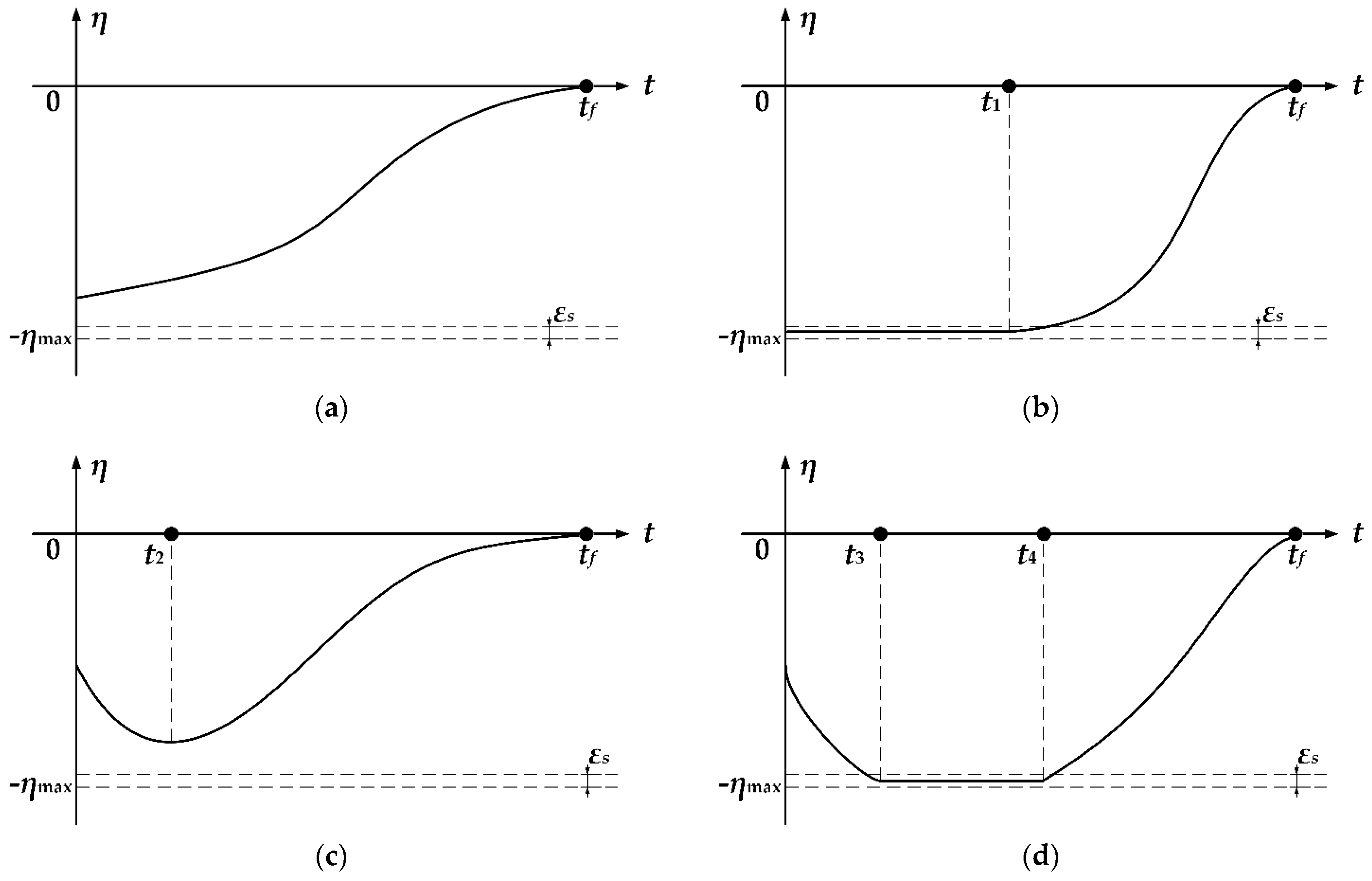
Under guidance law (36) and Algorithm 1, the change in the lead angle with respect to t can be divided into four cases. Without loss of generality, taking η(0) < 0 as an example, the relationship between η and t in four cases is shown in Figure 2. These four cases need to be analyzed separately.
(1)
ts1(0) ≥ ts0(0). This case is shown in Figure 2a, and the coefficient ts = ts1 = tft throughout the process. It can be seen that ts is continuous with respect to t, and |η| converges monotonically.
(2)
Ts1(0) < ts0(0) and ε(0) ≤ εs. This case is shown in Figure 2b. ts1 = ts0 is satisfied at the time instant t = t1. For t ∈ [0, t1], we take ts = ts0, and the lead angle remains unchanged. For t ∈ (t1, tf], we take ts = ts1, and |η| converges monotonically. It can be observed that the coefficient ts is continuous at the switching point t = t1.
(3)
ts1(0) < ts0(0), ε(0) > εs and the value of the lead angle does not increase to ηmax. This case is shown in Figure 2c. For t ∈ [0, t2], we take ts = max{ts1, ts2} < ts0, and |η| increases monotonically. ts1 = ts0 is satisfied at the time instant t = t2. Note that ts = max{ts1, ts2} = ts1 at t = t2 because ts2 < ts0. For t ∈ [t2, tf], we take ts = ts1. It can be seen that the coefficient ts is continuous at the switching point t = t2.
(4)
ts1(0) < ts0(0), ε(0) > εs and the value of the lead angle increases to ηmax. This case is shown in Figure 2d. For t ∈ [0, t3], we take ts = max{ts1, ts2}, and |η| increases monotonically. ts1 < ts0 and ts2ts0 at the time instant t = t3. For t ∈ (t3, t4], we take ts = ts0, and the lead angle remains unchanged. ts1 = ts0 is satisfied at the time instant t = t4. For t ∈ (t4, tf], we take ts = ts1, and |η| converges monotonically. The coefficient ts is continuous at the switching points t = t3 and t = t4.
Based on the analysis of the above four cases, it can be concluded that ts is continuous with respect to t under guidance law (36) and Algorithm 1. This completes the proof. □
Proposition 5.
For system (10), by using guidance law (36) and Algorithm 1, the constraint of time-varying coefficient ts in (37) can be guaranteed.
Proof of Proposition 5.
It can be mentioned that if ts1 < ts0 (before Phase A), regardless of whether tsts0 or ts ← max{ts1, ts2}, tsts0 is satisfied. Therefore, tsts0 < −4x1/x2 can be guaranteed before Phase A. If ts1ts0 (in Phase A), tsts1 and the guidance law is the same as (35). Hence, we should prove that ts = tft ≤ −4x1/x2 under (35). For convenience, define function H(t) as
H ( t ) = t f t + 4 x 1 / x 2
The derivative of H with respect to t can be obtained as follows:
H ˙ ( t ) = 1 + 4 ( 1 x 1 x ˙ 2 / x 2 2 ) = 3 + 4 F ( x 1 , x 2 , t ) x 1 / x 2 2 = [ x 2 ( t f t ) + 4 x 1 ] [ x 2 ( t f t ) + 12 x 1 ] / x 2 2 / ( t f t ) 2 = H ( t ) [ x 2 ( t f t ) + 12 x 1 ] / x 2 / ( t f t ) 2
In (44), it can be observed that if H < 0, H ˙   >   0 ; if H = 0, H ˙ = 0 . Denote the starting time of Phase A as t = tA; if tA = 0, we can choose tf ≤ −4x1(0)/x2(0) to obtain H(tA) ≤ 0; if tA > 0, it has been mentioned that Phase A begins at ts1ts0, so ts(tA) = ts1(tA) = ts0(tA) and we can obtain:
H ( t A ) = t f t A + 4 x 1 ( t A ) / x 2 ( t A ) = ( 8 2 10 ) x 1 ( t A ) / x 2 ( t A ) < 0
According to (44) and (45), for t ∈ [tA, tf), it can be seen that H ≤ 0 in Phase A; that is, ts = tft ≤ −4x1/x2 can be satisfied in Phase A. Therefore, it can be concluded that the constraint of coefficient ts in (37) can be guaranteed. This completes the proof. □
Remark 6.
The ITCG law in (36) finally converges to (35). When t → tf, we get tf − t → 0, x1(tf) → 0 and x2(tf) → 0. To avoid the adverse effect of terminal calculation error on the performance of guidance law (36), guidance law (36) is switched to PNG law when |η| ≤ ηmin. ηmin is a small positive constant defined as the threshold for switching the guidance law.

5. Simulation and Analysis

5.1. Performance Analysis of the Proposed Guidance Law

In this paper, two ITCG laws with FOV constraints are proposed: one is the open-loop guidance law (13), and the other is the modified closed-loop guidance law (36). Note that the guidance law (36) is not just a simple closed-loop modification of the guidance law (13). Compared with (13), (36) can make more use of the seeker’s maximum detection capability. Obviously, the performance of the guidance law (36) is improved compared with (13). In this subsection, the effectiveness of the open-loop guidance law (13) and closed-loop guidance law (36) with Algorithm 1 is verified.
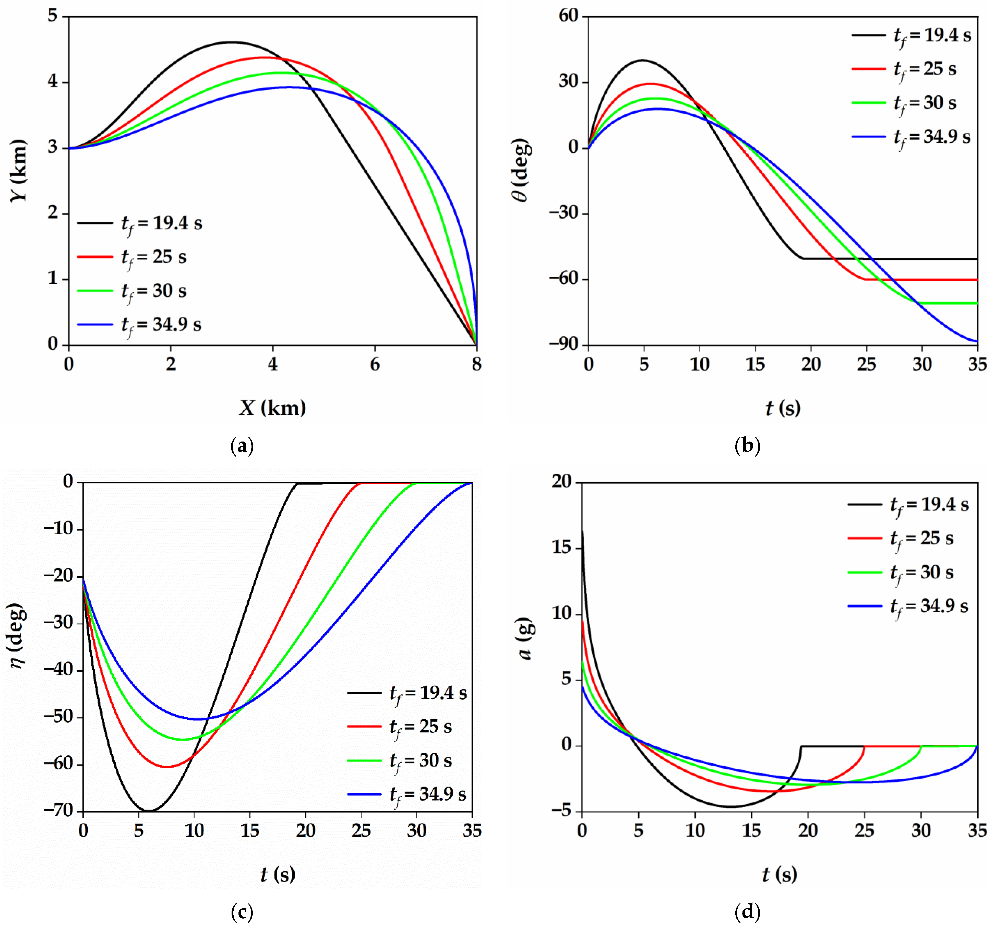
For the simulation of the guidance law (13), we want to show the influence of different convergence time tf on the performance of the guidance law. The desired impact time is set to td = 35 s, and the specified convergence time is set to tf = 19.4 s, 25 s, 30 s and 34.9 s, respectively. The input saturation is not considered. For the simulation of the guidance law (36), we want to demonstrate the performance of the guidance law under different impact time td. The desired impact time is set to td = 30 s, 35 s, 40 s, 45 s and 50 s, respectively. The specified convergence time is set to tf = td − 0.1. The maximum allowable acceleration is set to amax = 5 g, where g is the acceleration of gravity. Other necessary simulation parameters under the two guidance laws are as follows: The initial coordinates of the missile are (0, 3000) m, and the coordinates of the stationary target are (8000, 0) m. The velocity of the missile is set to VM = 300 m/s, and the initial flight path angle is set to θ = 0°. The maximum allowable lead angle is set to ηmax = 70°. The threshold constants εs and ηmin are set to 0.01° and 0.5°, respectively. The navigation gain of PNG law is set to 3.
The simulation results of the open-loop guidance law (13) are shown in Figure 3. It can be seen from Figure 3a,b that under different values of coefficient tf, the flight trajectory of the missile is different, but all of them can achieve target interception and impact time constraint. In addition, the flight path angle of the missile remains constant after t = tf; that is, the missile flies along the collision path. Figure 3c shows the variation in the lead angle under different values of tf. When tf = 19.4 s, the maximum lead angle reaches ηmax. Therefore, to satisfy the FOV constraint, the specified coefficient tf cannot be less than 19.4 s. It can be verified by numerical calculation that tf = 19.4 s is also the solution of (28) in this simulation scenario. The missile acceleration profile is shown in Figure 3d. It can be observed that the smaller the convergence time tf is, the larger the required maximum acceleration command a. In addition, the acceleration command a is continuous and converges to 0 at t = tf. Therefore, the coefficient tf has a great influence on the performance of the guidance law (13).
The simulation results of closed-loop guidance law (36) are shown in Figure 4. The missile trajectory and the variation in flight path angle are shown in Figure 4a,b, respectively. It can be found that the missile can hit the target under different desired impact times. In addition, the longer the specified impact time, the more curved the flight trajectory and the larger the terminal flight path angle. Figure 4c shows the variation of lead angle. It can be seen that the FOV constraint of the seeker is not violated. For the cases of td = 45 s and td = 50 s, the lead angle reaches the maximum value ηmax and remains at ηmax for a period. The variation in coefficient ts determined by Algorithm 1 is shown in Figure 4d. It can be seen that the change in ts with respect to t is approximately continuous. For the cases of td = 45 s and td = 50 s, when the time t is approximately 15 s and 21 s, respectively, there is a slight jump in ts. The slight jump is caused by the threshold parameter εs in Algorithm 1. Figure 4e shows the change in the acceleration command over time, and it can also be seen that the acceleration command is continuous and finally converges to 0.

5.2. Comparative Work

The effectiveness of the proposed guidance laws is verified in Section 5.1. To verify the superiority of the proposed method, comparative work is carried out in this subsection. The ITCG law with FOV constraint proposed in [18,21,24] is selected for comparison with the closed-loop guidance law (36). The ITCG law in [18] has a simple structure and is easy to implement. The ITCG law in [21] is also designed based on the sliding mode control method. In [24], the authors’ design goal is similar to that of this paper—that is, to ensure that the missile is on the collision path against the target. In this subsection, two simulation scenarios are selected to examine the performance of the above four ITCG laws. In addition, the allowable impact time range of the four guidance laws under these two scenarios is analyzed quantitatively.
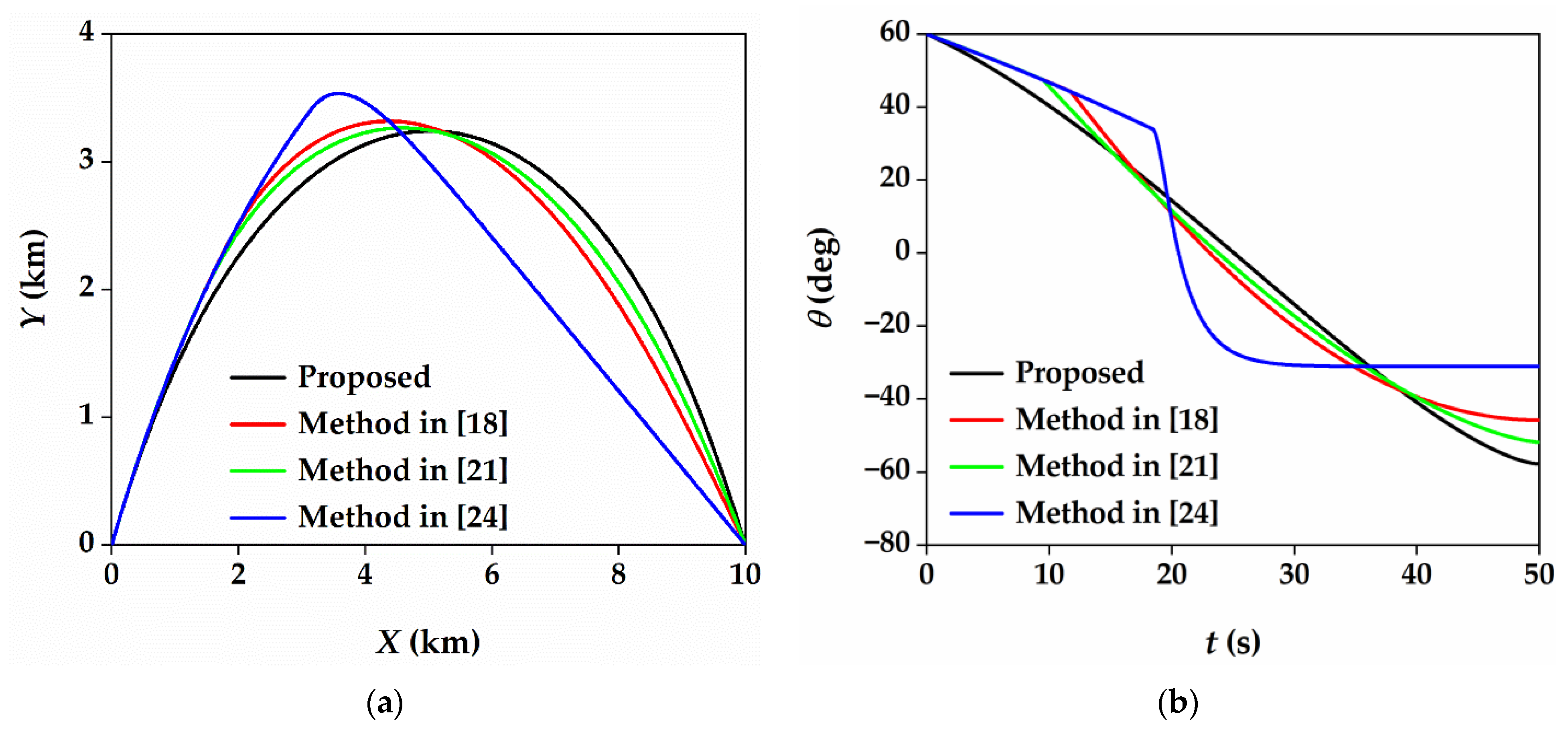
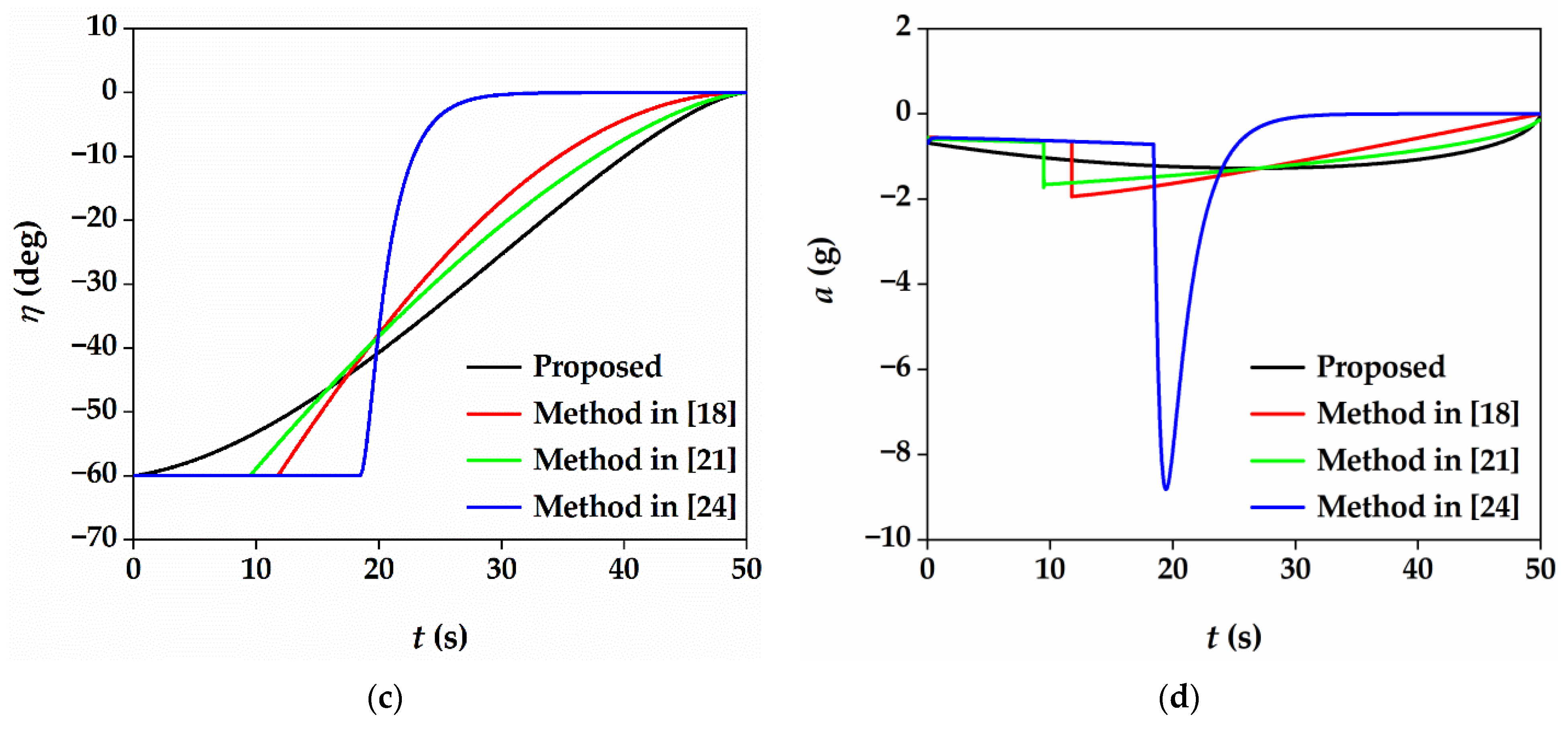
The initial coordinates of the missile are (0, 0) m, and the coordinates of the stationary target are (10,000, 0) m. The velocity of the missile is set to VM = 250 m/s, and the maximum lead angle is set to ηmax = 60°. The maximum allowable acceleration is set to amax = 10g. The desired impact time is set to td = 50 s. In scenario 1, the initial flight path angle is set to θ = 40°, and the initial lead angle is less than ηmax. In scenario 2, the initial flight path angle is set to θ = 60°, and the initial lead angle is equal to ηmax. Under the proposed guidance law (36), the values of the threshold constants and navigation gain are the same as those in Section 5.1. The coefficients required by the other three ITCG laws can be referred to [18,21,24].
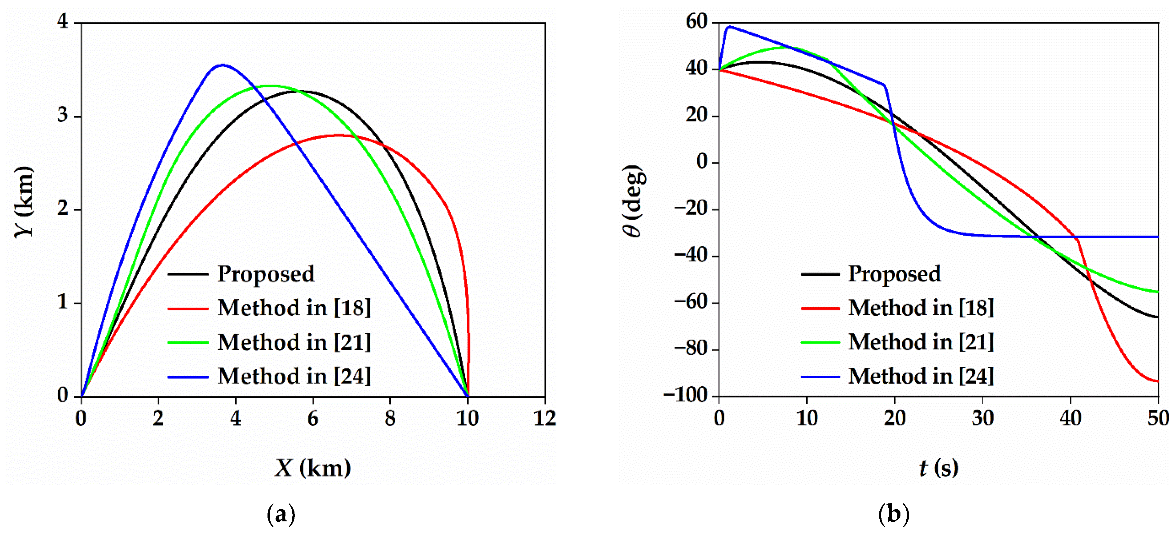
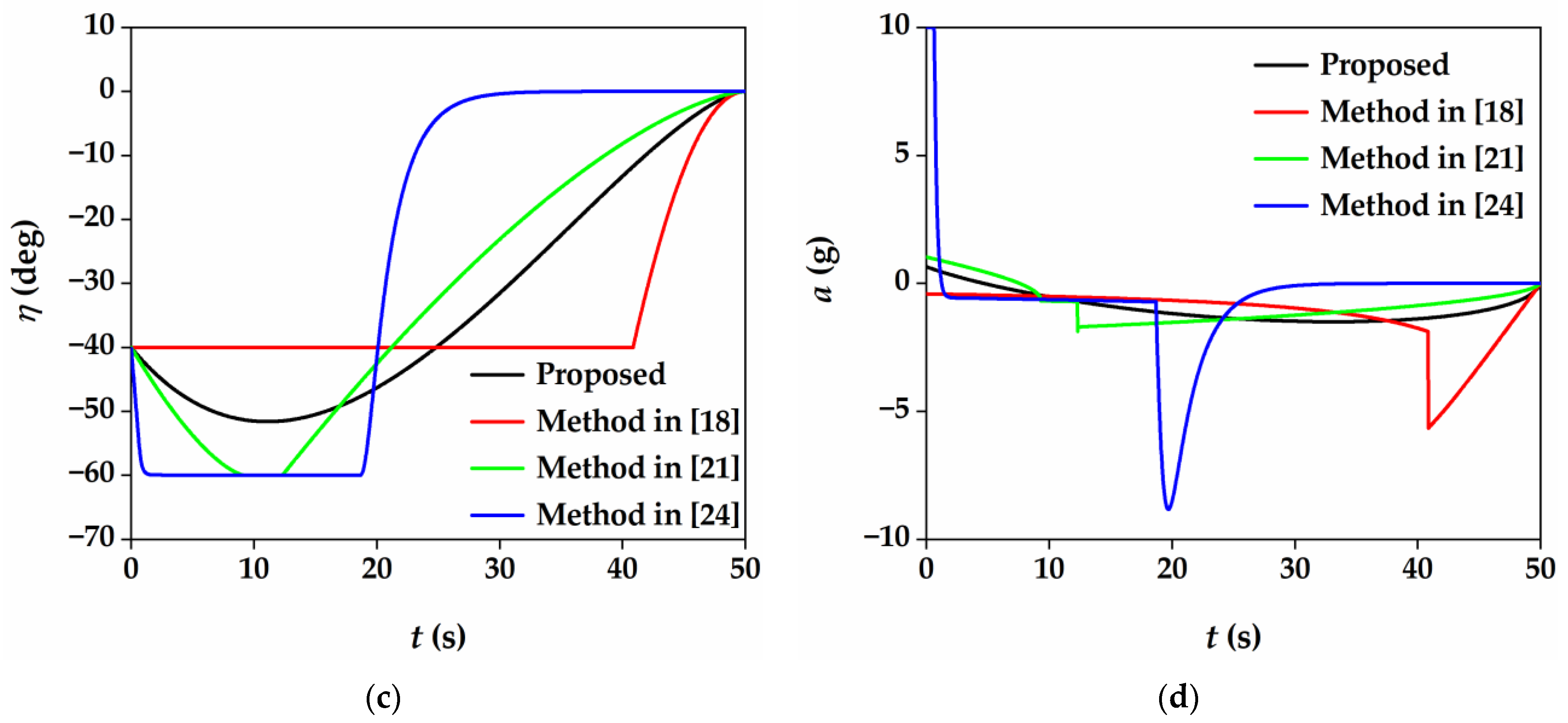
The simulation results of scenario 1 are shown in Figure 5. The flight trajectory and flight path angle of the missile under the four guidance laws are shown in Figure 5a,b, respectively. Using these four guidance laws, the missile not only can intercept the target but also can ensure the impact time constraint. Compared with the methods in [18,21,24], the flight path angle changes relatively smoothly under the proposed method. Figure 5c shows the change in the lead angle η with respect to t. It can be seen that under the methods in [21,24], the value of η first increases to ηmax and then converges to 0. The value of η is nonincreasing under the method in [18]. Under the proposed method, the value of η first increases and does not reach ηmax, and then converges to 0. In terms of the maximum utilization of the seeker’s detection capability, the method in [24] is the best, and the method in [18] is the worst. Figure 5d shows the missile acceleration under the four methods. With these four methods, the acceleration command finally converges to 0. The maximum acceleration required by the methods in [18,24] is significantly larger than that of the other two methods. The maximum acceleration required by the method in [21] is slightly larger than that under the proposed method, and the acceleration command jump occurs near t = 12 s. Under the proposed method, the acceleration command is continuous, and the required maximum acceleration is the smallest.
The simulation results of scenario 2 are shown in Figure 6. Under this simulation scenario, the initial lead angle is equal to the allowable maximum lead angle, so this simulation scenario is more suitable for the method in [18] because the lead angle value is nonincreasing under the method in [18]. The simulation results are similar to those in scenario 1. A significant difference is that in scenario 2, the maximum acceleration required by the method in [18] is significantly reduced. We can see that these four methods can also achieve impact time control with FOV constraint. In addition, using the proposed method, the guidance command is continuous, and the required maximum acceleration command is the smallest.
In the aforementioned two simulation scenarios, the desired impact time is set to td = 50 s. Obviously, the allowable range of td is different under different ITCG laws. For many ITCG laws, it is difficult to give a precise allowable range of td through theoretical analysis. Therefore, we obtain the allowable range of td in the two scenarios through numerical simulation. Taking into account the actual combat scenario, it is stipulated that the allowable td needs to ensure that Y ≥ 0 during the guidance process. The quantitative results are shown in Table 1. The maximum allowable impact time is denoted as tdmax, and the minimum allowable impact time is denoted as tdmin. It can be seen that under the method in [18], the value of tdmin is relatively large, and the value of tdmin under the other three methods has little difference. In the case of θ0 = 60°, the values of tdmax under the four methods are very close. In the case of θ0 = 40°, the value of tdmax under the method in [18] is significantly smaller than that of the other three methods. This is because the lead angle value is nonincreasing under the method in [18]. It can be seen that the value of tdmax is the largest under the method in [24]. The value of tdmax under the proposed method is 4.5 s smaller than that under the method in [24]. These results can be explained by Figure 5c,d.

5.3. Salvo Attack Analysis

The scenario of a multiple missile salvo attack is simulated in this subsection. In practice, the dynamics of autopilot should be considered to examine its influence on guidance performance. We assume that all the missiles have the same autopilot, which can be modeled as a first-order transfer function as
a a c = 1 1 + τ s
where ac is the commanded acceleration, and a is the achieved acceleration. The time constant τ is chosen as τ = 0.5 s.
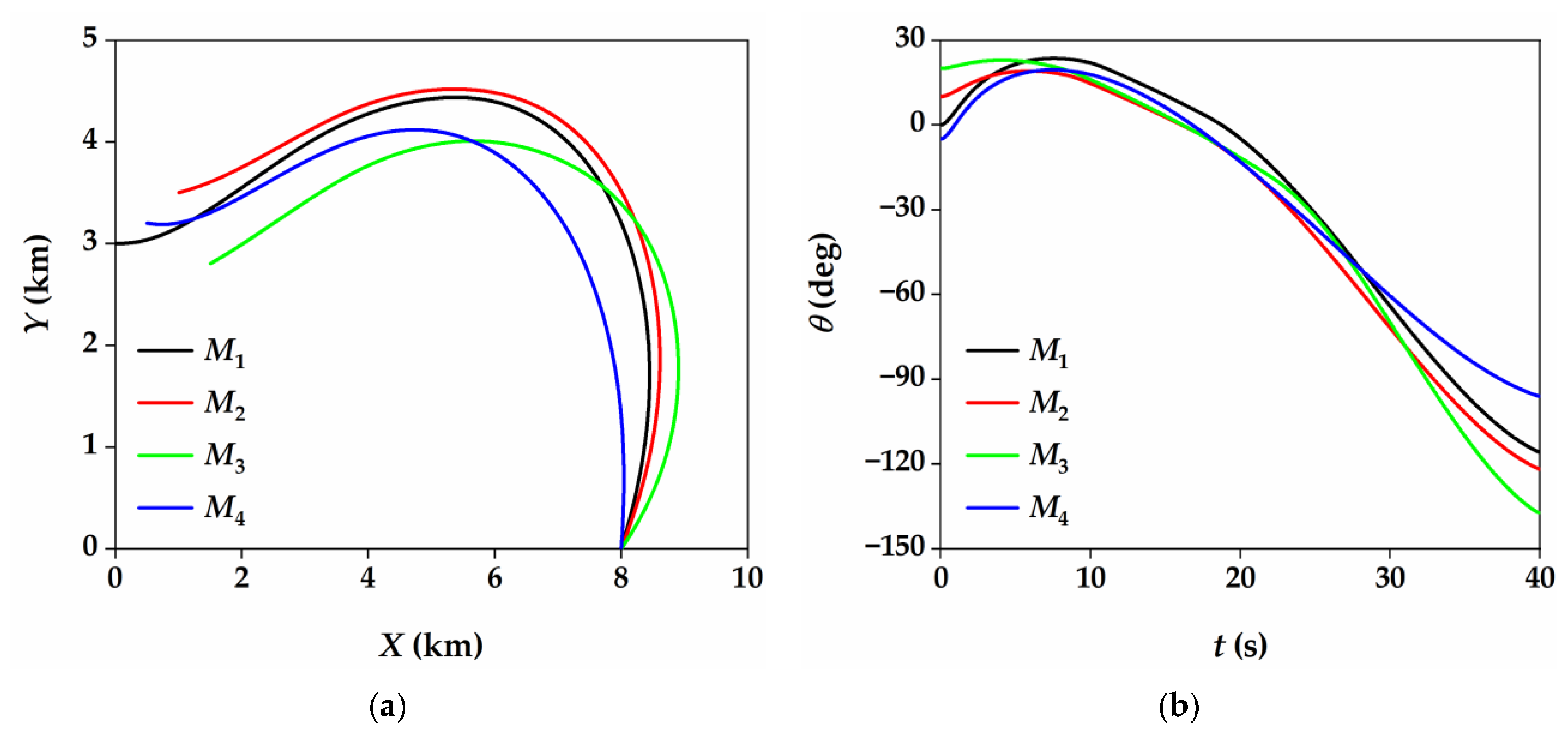
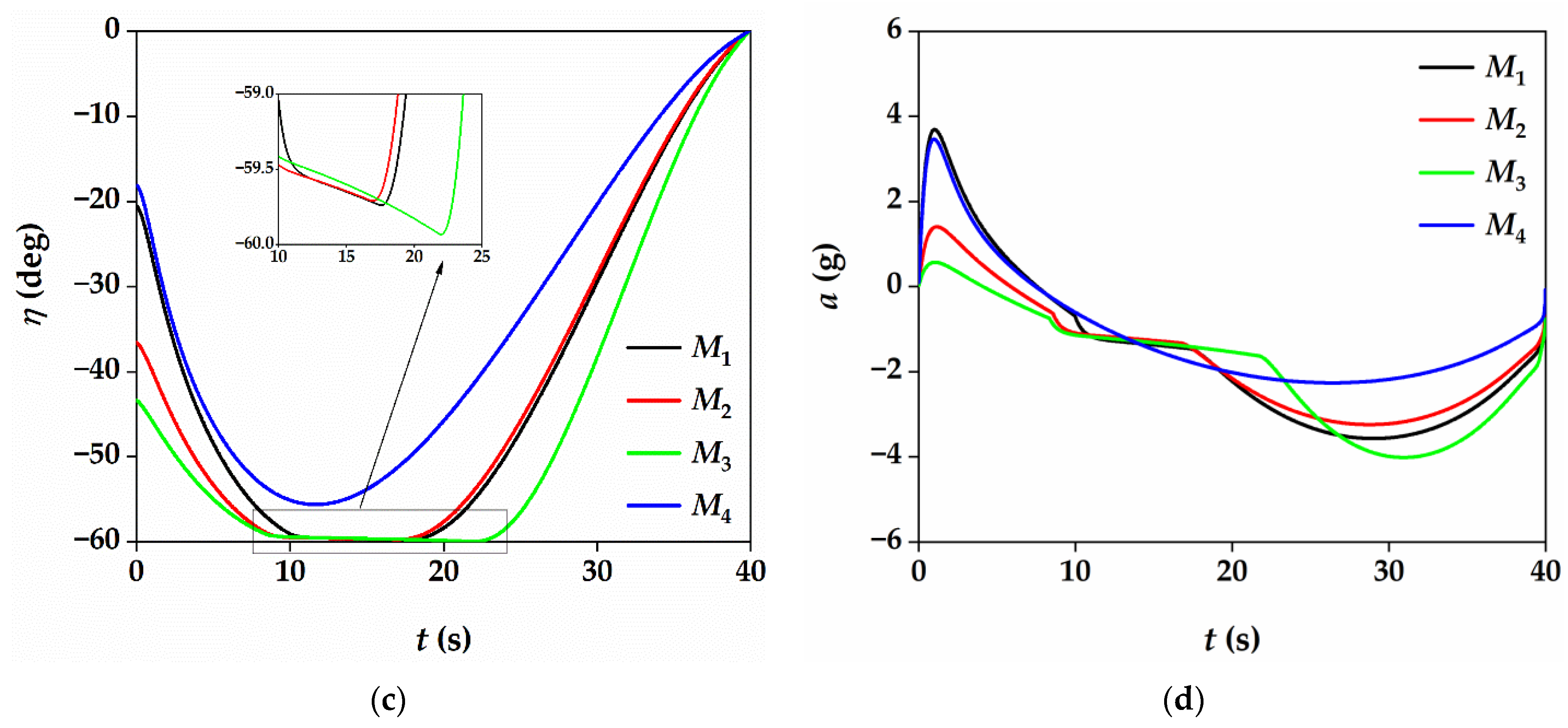
Consider four missiles participating in a salvo attack. The missiles are denoted as M1, M2, M3 and M4. The initial parameters of the missiles are shown in Table 2. The stationary target is located at (8000, 0) m. The allowable maximum lead angle is set to ηmax = 60°. The desired impact time is set to td = 40 s, and the convergence time is set to tf = 39.9 s. The allowable maximum acceleration command is set to amax = 5 g. The threshold constants and navigation gain under the PNG law are the same as those in Section 5.2.
The simulation results are shown in Figure 7. Figure 7a,b shows that all the missiles can hit the target at the specified impact time. The change of lead angle is shown in Figure 7c. It can be observed that the lead angles of M1, M2 and M3 reach the maximum value ηmax and remain for a period. None of the missiles violate the FOV constraint. The achieved acceleration commands of the missiles are shown in Figure 7d. It can be observed that the acceleration command is continuous and eventually converges to 0. Simulation results demonstrate the robustness and feasibility of the proposed guidance law, and it can be used for a salvo attack of multiple missiles.

6. Conclusions

A novel ITCG law with FOV constraint is derived based on the time-varying sliding mode technique. In view of the open-loop structure, the guidance law is modified to a closed-loop structure, which can make use of the seeker’s maximum detection capability to a greater extent. The proposed guidance law does not require the small angle assumption or time-to-go estimation. Simulation results show that the maximum acceleration command required by the proposed guidance law is small; in addition, the acceleration command is continuous and converges to 0 at the specified time. The proposed guidance law can also be used in salvo attack scenarios. On this basis, the impact time control under velocity variation and terminal impact angle constraint will be considered in subsequent research.

Author Contributions

Conceptualization, S.M. and X.W.; methodology, S.M. and Z.W.; software, S.M.; validation, X.W. and Z.W.; writing—original draft preparation, S.M.; writing—review and editing, X.W. and Z.W.; funding acquisition, X.W. All listed authors meet the ICMJE criteria, and all who meet the four criteria are identified as authors. We attest that all authors contributed significantly to the creation of this manuscript, each having fulfilled criteria as established by the ICMJE. We confirm that the manuscript has been read and approved by all named authors. We confirm that the order of authors listed in the manuscript has been approved by all named authors. All authors have read and agreed to the published version of the manuscript.

Funding

This work was supported by the Fundamental Research Funds for the Central Universities (number 30919011401).

Institutional Review Board Statement

Not applicable.

Informed Consent Statement

Not applicable.

Data Availability Statement

The data used to support the findings of this study are available from the corresponding author upon request.

Conflicts of Interest

The authors declare that they have no conflicts of interest.

References

  1. Jeon, I.S.; Lee, J.I.; Tahk, M.J. Impact-time-control guidance law for anti-ship missiles. IEEE Trans. Control Syst. Technol. 2006, 14, 260–266. [Google Scholar] [CrossRef]
  2. Jeon, I.-S.; Lee, J.-I.; Tahk, M.-J. Homing Guidance Law for Cooperative Attack of Multiple Missiles. J. Guid. Control Dyn. 2010, 33, 275–280. [Google Scholar] [CrossRef]
  3. Chen, Y.D.; Wang, J.A.; Shan, J.Y.; Xin, M. Cooperative Guidance for Multiple Powered Missiles with Constrained Impact and Bounded Speed. J. Guid. Control Dyn. 2021, 44, 825–841. [Google Scholar] [CrossRef]
  4. Kumar, S.R.; Mukherjee, D. Terminal Time-Constrained Nonlinear Interception Strategies Against Maneuvering Targets. J. Guid. Control Dyn. 2021, 44, 200–209. [Google Scholar] [CrossRef]
  5. Sinha, A.; Kumar, S.R.; Mukherjee, D. Three-Dimensional Guidance with Terminal Time Constraints for Wide Launch Envelops. J. Guid. Control Dyn. 2021, 44, 343–359. [Google Scholar] [CrossRef]
  6. Jeon, I.-S.; Lee, J.-I.; Tahk, M.-J. Impact-Time-Control Guidance with Generalized Proportional Navigation Based on Nonlinear Formulation. J. Guid. Control Dyn. 2016, 39, 1885–1890. [Google Scholar] [CrossRef]
  7. Cho, D.; Kim, H.J.; Tahk, M.-J. Nonsingular Sliding Mode Guidance for Impact Time Control. J. Guid. Control Dyn. 2016, 39, 61–68. [Google Scholar] [CrossRef]
  8. Yang, Z.; Wang, H.; Lin, D.; Zang, L. A New Impact Time and Angle Control Guidance Law for Stationary and Nonmaneuvering Targets. Int. J. Aerosp. Eng. 2016, 2016, 1–14. [Google Scholar] [CrossRef]
  9. Hu, Q.; Han, T.; Xin, M. New Impact Time and Angle Guidance Strategy via Virtual Target Approach. J. Guid. Control Dyn. 2018, 41, 1755–1765. [Google Scholar] [CrossRef]
  10. Chen, X.; Wang, J. Sliding-Mode Guidance for Simultaneous Control of Impact Time and Angle. J. Guid. Control Dyn. 2019, 42, 394–401. [Google Scholar] [CrossRef]
  11. Tekin, R.; Erer, K.S. Impact Time and Angle Control Against Moving Targets with Look Angle Shaping. J. Guid. Control Dyn. 2020, 43, 1020–1025. [Google Scholar] [CrossRef]
  12. Zhang, Y.; Wang, X.; Wu, H. Impact time control guidance law with field of view constraint. Aerosp. Sci. Technol. 2014, 39, 361–369. [Google Scholar] [CrossRef]
  13. Zhang, Y.; Wang, X.; Wu, H. Impact time control guidance with field-of-view constraint accounting for uncertain system lag. Proc. Inst. Mech. Eng. Part G J. Aerosp. Eng. 2015, 230, 515–529. [Google Scholar] [CrossRef]
  14. Shim, S.-W.; Hong, S.-M.; Moon, G.-H.; Tahk, M.-J. Impact Angle and Time Control Guidance Under Field-of-View Constraints and Maneuver Limits. Int. J. Aeronaut. Space Sci. 2018, 19, 217–226. [Google Scholar] [CrossRef]
  15. Kim, H.G.; Lee, J.Y.; Kim, H.J.; Kwon, H.H.; Park, J.S. Look-Angle-Shaping Guidance Law for Impact Angle and Time Control With Field-of-View Constraint. IEEE Trans. Aerosp. Electron. Syst. 2020, 56, 1602–1612. [Google Scholar] [CrossRef]
  16. He, S.; Lee, C.-H.; Shin, H.-S.; Tsourdos, A. Optimal three-dimensional impact time guidance with seeker’s field-of-view constraint. Chin. J. Aeronaut. 2021, 34, 240–251. [Google Scholar] [CrossRef]
  17. Jeon, I.-S.; Lee, J.-I. Impact-Time-Control Guidance Law With Constraints on Seeker Look Angle. IEEE Trans. Aerosp. Electron. Syst. 2017, 53, 2621–2627. [Google Scholar] [CrossRef]
  18. Lee, S.; Cho, N.; Kim, Y. Impact-Time-Control Guidance Strategy with a Composite Structure Considering the Seeker’s Field-of-View Constraint. J. Guid. Control Dyn. 2020, 43, 1566–1574. [Google Scholar] [CrossRef]
  19. Mukherjee, D.; Kumar, S.R. Nonlinear Impact Time Guidance with Constrained Field-of-View. In Proceedings of the 2020 American Control Conference (ACC), Denver, CO, USA, 1–3 July 2020; pp. 3802–3807. [Google Scholar]
  20. Mukherjee, D.; Kumar, S.R. Field-of-View Constrained Impact Time Guidance against Stationary Targets. IEEE Trans. Aerosp. Electron. Syst. 2021, in press. [Google Scholar] [CrossRef]
  21. Chen, X.; Wang, J. Nonsingular Sliding-Mode Control for Field-of-View Constrained Impact Time Guidance. J. Guid. Control Dyn. 2018, 41, 1214–1222. [Google Scholar] [CrossRef]
  22. Tekin, R.; Erer, K.S.; Holzapfel, F. Impact Time Control with Generalized-Polynomial Range Formulation. J. Guid. Control Dyn. 2018, 41, 1190–1195. [Google Scholar] [CrossRef]
  23. Kim, H.-G.; Kim, H.J. Impact time control guidance considering seeker’s field-of-view limits. In Proceedings of the 2016 IEEE 55th Conference on Decision and Control (CDC), Las Vegas, NV, USA, 12–14 December 2016; pp. 4160–4165. [Google Scholar]
  24. Kim, H.-G.; Kim, H.J. Backstepping-Based Impact Time Control Guidance Law for Missiles With Reduced Seeker Field-of-View. IEEE Trans. Aerosp. Electron. Syst. 2019, 55, 82–94. [Google Scholar] [CrossRef]
  25. Ha, I.-J.; Hur, J.-S.; Ko, M.-S.; Song, T.-L. Performance analysis of PNG laws for randomly maneuvering targets. IEEE Trans. Aerosp. Electron. Syst. 1990, 26, 713–721. [Google Scholar] [CrossRef]
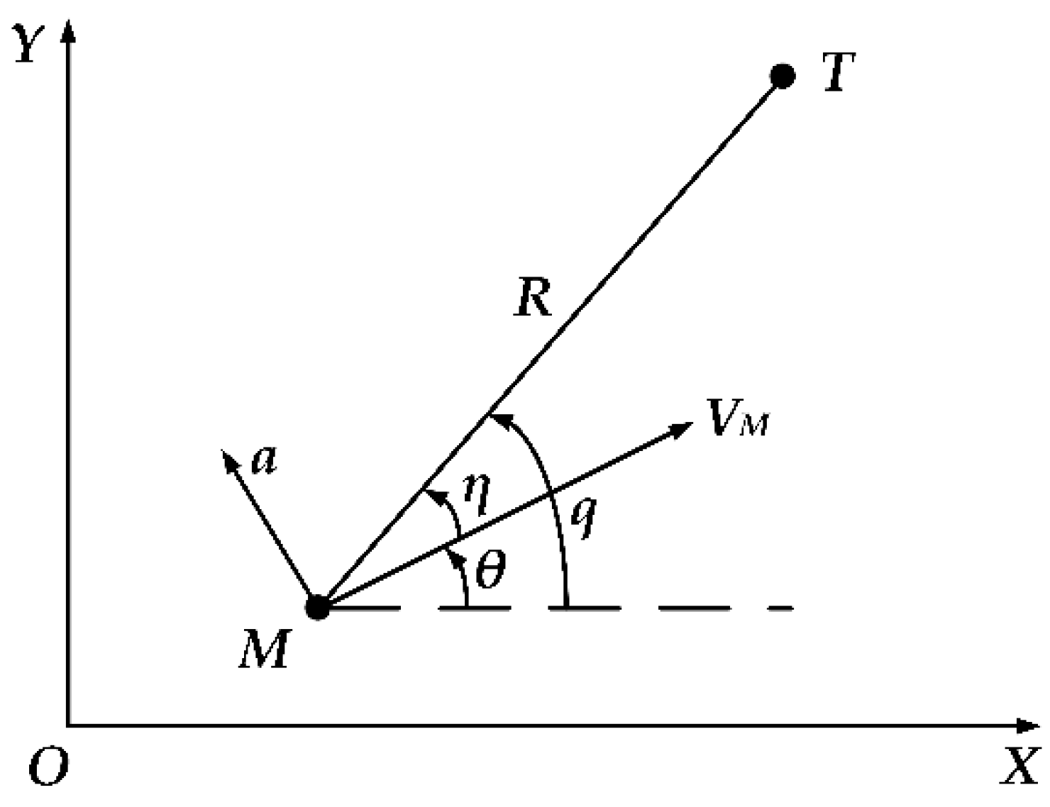
Figure 1. Planar homing engagement geometry.
Aerospace 08 00251 g001
Figure 2. Four cases of lead angle with respect to t: (a) Variation of lead angle under case 1; (b) Variation of lead angle under case 2; (c) Variation of lead angle under case 3; (d) Variation of lead angle under case 4.
Aerospace 08 00251 g002
Figure 3. Simulation results of (19) under different values of coefficient tf. (a) Missile flight trajectory; (b) Flight path angle; (c) Lead angle; (d) Missile acceleration.
Aerospace 08 00251 g003
Figure 4. Simulation results of (36) under different desired impact times. (a) Missile flight trajectory; (b) Flight path angle; (c) Lead angle; (d) Profile of coefficient ts; (e) Missile acceleration.
Aerospace 08 00251 g004
Figure 5. Simulation results of θ0 = 40° under different guidance laws. (a) Missile flight trajectory; (b) Flight path angle; (c) Lead angle; (d) Missile acceleration.
Aerospace 08 00251 g005aAerospace 08 00251 g005b
Figure 6. Simulation results of θ0 = 60° under different guidance laws. (a) Missile flight trajectory; (b) Flight path angle; (c) Lead angle; (d) Missile acceleration.
Aerospace 08 00251 g006aAerospace 08 00251 g006b
Figure 7. Simulation results of a 4 missile salvo attack. (a) Missile flight trajectory; (b) Flight path angle; (c) Lead angle; (d) Missile achieved acceleration.
Aerospace 08 00251 g007aAerospace 08 00251 g007b
Table 1. Allowable impact time range under the four ITCG laws.
θ0 = 40°θ0 = 60°
tdmin (s)tdmax (s)tdmin (s)tdmax (s)
Proposed40.467.441.171.2
Method in [18]42.151.444.872.2
Method in [21]40.669.941.471.7
Method in [24]40.571.940.872.1
Table 2. Initial parameters of four missiles.
X0 (m)Y0 (m)VM (m/s)θ0 (°)
M1030003000
M21000350028010
M31500280027020
M45003200260−5
Publisher’s Note: MDPI stays neutral with regard to jurisdictional claims in published maps and institutional affiliations.