Article

VHF Omnidirectional Range (VOR) Experimental Positioning for Stratospheric Vehicles

1
Department of Astronautical, Electric and Energy Engineering, Sapienza University of Rome, via Eudossiana 18, 00184 Rome, Italy
2
Department of Mechanical and Aerospace Engineering, Sapienza University of Rome, via Eudossiana 18, 00184 Rome, Italy
*
Author to whom correspondence should be addressed.
Aerospace 2021, 8(9), 263; https://doi.org/10.3390/aerospace8090263
Submission received: 9 August 2021 / Revised: 4 September 2021 / Accepted: 11 September 2021 / Published: 15 September 2021
(This article belongs to the Special Issue New Space: Advances in Space Science and Engineering)

Abstract

:
The usage of aeronautical radio-frequency navigational aids can support the future stratospheric aviation as back-up positioning systems. Although GNSS has been extensively redundant in the last years of space operations, radio NavAids can still be supportive of navigation and tracking for novel mission profiles. As an example, in 2016, VHF Omnidirectional Range (VOR) has been proven to work well above its standard service volume limit on a stratospheric balloon flight with the STRATONAV experiment. While VOR provides the “radial” measurement, i.e., the angle between the Magnetic North and the line between the receiver and the transmitting ground station, the intersection of two or more radials at a time allows to perform ground track reconstruction for the vehicle to be tracked. This paper reports the results from the data re-processing from STRATONAV: the acquired radials have been intersected in order to achieve positioning. The radials interfacing method, the position calculation methodology, and the data acquisition strategies from STRATONAV are reported together with the data analysis results.

1. Introduction

In the extremely complex scenario of the so-called New Space Economy, stratospheric missions are obtaining an increasingly important role due to their effective capabilities of performing quasi-satellite tasks with lower development and installation costs, when compared to orbital platforms [1]. To support the emerging mission concepts for stratospheric payloads and for this transfer from space science to near-space missions [1,2], the future operations of stratospheric airships, High Altitude Platform Stations (HAPSs), and stratospheric vehicles will require an improvement of the navigation systems reliability for achieving more accurate navigation, station-keeping tasks, and positioning [3,4,5,6,7,8]. The utilization of a secondary navigation system, as back-up for than Global Navigation Satellite System (GNSS), can introduce a further improvement to the navigation systems reliability and to the mission execution itself [9,10,11]. Aeronautical Navigational Aids (NavAids) can support these new concept mission profiles with an extension of their usual service volume. Passive NavAids, such as the VHF Omnidirectional Range (VOR, [12,13,14]), can support the missions by requiring only passive Radio-Frequency (RF) airborne hardware, thus simplifying the architecture of the additional navigation systems on-board the stratospheric platforms. Although GNSS is currently already redundant (with several governmental systems active and operational) and aeronautical ground-based NavAids can be supporting similar missions only when overflying land, these NavAids can provide further support to stratospheric missions with an additional, independent navigation system.
These navigation systems are generally not allowing the users to directly achieve positioning, while the absolute position determination is in general possible through further processing of the measurements. For example, the VOR system outputs the radial information, which equals the bearing angle of the line between the airborne receiver and the VOR ground station with respect to the Magnetic North, without any information on the actual position of the receiver [12]. If intersecting two radials, it is possible to calculate the latitude and longitude of the receiver.
The STRATONAV experiment, developed at Sapienza University of Rome for the REXUS/BEXUS Programme (aiming at launching European student experiments on-board stratospheric balloons and sounding rockets, [15]) has proven in 2016 the well-functioning of the VOR navigation system in stratospheric flight, while flying on a stratospheric balloon in Northern Sweden with an apogee of 32.2 km. The data analysis, described in [16], confirmed that the reliability of such navigation system in stratospheric flight is comparable to the current accuracy standards predicted by the International Civil Aviation Organization (ICAO, [12,17]) and they can satisfy the previous standard rates introduced in the first years of VOR operations.
After the accuracy determination analysis carried out with the data collected in stratosphere, the STRATONAV data have been re-processed with the aim of achieving positioning and ground-track estimation of the balloon trajectory by means of the VOR measurements stand-alone. This paper reports the results from the VOR-based positioning analysis carried out on the stratospheric balloon data from STRATONAV. The needed materials and methods, from an introduction on VOR to the data analysis principles and data collection processes adopted on STRATONAV, will be described in Section 2, while the obtained results from the conducted analyses will be presented in Section 3, before moving to the conclusions in Section 4.

2. Materials and Methods

2.1. VHF Omnidirectional Range (VOR)

VOR is a radio-navigational aid used for civil aviation since the late 1940s [12]. The system is based on a network of transmitting ground stations and on receiving-only airborne receivers. The aim of VOR is to provide the user with the radial information, which is the angle between the Magnetic North and the line between the airborne receiver and the ground station. When VOR was used as primary navigation system for the civil aviation, the pilots could divide their optimal (orthodromic) route into straight segments between different VOR stations [18], maintaining the radial value constant to fly towards the destination. For achieving the radial calculation, the receiver carries out several signal processing tasks that are described as follows:
  • At signal reception, the receiver discriminates two different sub-modulated signals, namely, an AM sub-modulated reference sine wave and a FM sub-modulated directional sine-wave;
  • The two sub-modulated sine waves are independently de-modulated and brought back to base band, at 30 Hz;
  • The phase of the two signals is then compared and the obtained value is re-scaled as an angle (with values between 0 and 360 degrees);
  • The radial information is the obtained value.
As visible, VOR replicates in VHF the old concept of lighthouse navigation, where the omnidirectional signal substitutes the lighthouse white light and the directional sine wave substitutes the lighthouse rotating green light. The role of the receiver is to passively decode the signal and calculate the phase shift between the signals, which will be, as an example, superposed when the radial is 0 degrees and opposed when the radial is 180 degrees [17,18].

2.2. STRATONAV Experiment and Data Collection Processes

STRATONAV is a student stratospheric experiment developed in 2016 by the S5Lab (Sapienza Space Systems and Space Surveillance Laboratory) research team at Sapienza University of Rome. The project aim was to verify the accuracy of VOR while flying in stratosphere, since the Standard Service Volume (SSV) of VOR does not reach beyond 18 km of height above ground, while link budget calculations suggest that a broader utilization is possible well above the predicted SSV end [19].
The experiment was selected in late 2015 for the ninth cycle of the REXUS/BEXUS Programme, managed by SNSA (Swedish National Space Agency), DLR (German Aerospace Center), and ESA (European Space Agency) for providing launch opportunities on-board sounding rockets and stratospheric balloons to European University students. The experiment was developed throughout 2016 at S5Lab by the student team, which was profiting from the lessons learned and the experience from previous space systems manufacturing projects carried out at the laboratory [20,21,22,23,24,25,26,27]. The experiment was launched on-board the BEXUS 22 stratospheric balloon from the Esrange Space Center in Kiruna (Sweden), on 5 October 2016 at 13.35 UTC. The balloon overflew the Swedish and Finnish Lapland with a ground track of approximately 240 km and a total flight time of approximately four hours [16].
The experiment was equipped with two different Radio-Frequency receivers in order to collect and detect VOR data:
  • A COTS (Commercial Off The Shelf) portable VOR receiver, able to autonomously receive and decode the signal and to show the calculated radial on the screen. This receiver was modified by the team in order to be able to tune in the different VOR frequencies and to externally log the detected radials. This receiver will be referred as “COTS receiver” from now on;
  • A Software Defined Radio (SDR) able to scan and record the frequencies of interest (from 108 MHz to 118 MHz). The recorded raw data was saved on a Solid State Drive (SSD) and post-processed after the experiment recovery after landing. This device will be referred from now on as “SDR receiver” in the paper.
In order to be able to compare the collected data accuracy to real positioning data, a commercial GPS (Global Positioning System) receiver with native interconnectivity with the selected On-Board Data Handling System [28] was included in the experiment box. After the flight, the GPS data retrieved by the experiment were compared and validated with the navigation and positioning data made available by the launch base team for the balloon.
STRATONAV managed to acquire a large amount of data throughout the flight. The VOR radials were proven to be within the previous ICAO standard accuracy rates for the 99% of the collected samples. The experiment profited by a very high number of VOR ground stations installed in the flight area (i.e., Swedish and Finnish Lapland) [29,30,31].
Concerning the positioning data, the samples collected by the COTS receiver are much less than the ones collected by the SDR. This is justified by the data collection processes: while the SDR scans the VHF band, recording all the VOR signals in the band, thus accessing at many VOR radials at a time, the COTS receiver can be tuned to a single frequency. The positioning samples, requiring two (or more) radials from different stations, can be collected only when the COTS receiver changes its tuning frequency between two active VOR stations.

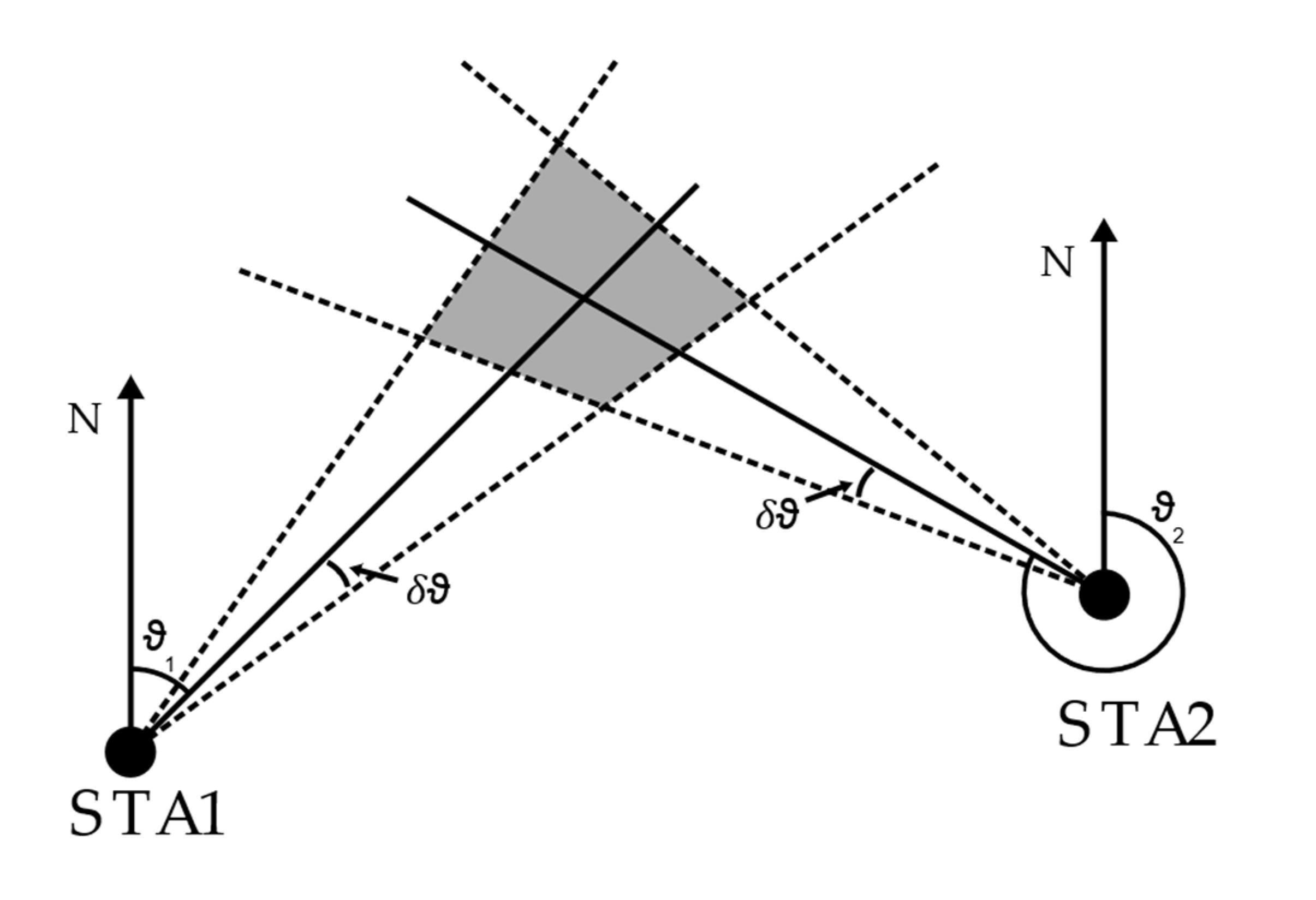
2.3. VOR-Based Ground Track Determination

Two-dimensional positioning (determination of ground track) can be achieved when intersecting two or more radial measurements acquired simultaneously. Latitude and longitude of the balloon position are retrieved as follows.
Given φ1, λ1, θ1, namely, the latitude, longitude, and measured radial from the first station, and φ2, λ2, θ2 from the second station, the positioning formula is obtained from the following formulas.
As first step, it is necessary to calculate the angular distance between the two VOR station points, defined as δ12.
δ 12 = 2 · sin 1 ( s i n 2 ( φ 1 φ 2 2 ) + cos φ 1 · cos φ 2 · sin 2 ( λ 1 λ 2 2 ) .
It is then necessary to compute the bearings between the two VOR stations positions.
ϑ a = 2 · acos ( sin φ 2 sin φ 1 · cos δ 12 sin δ 12 · cos φ 1 ) , ϑ b = 2 · acos ( sin φ 1 sin φ 2 · cos δ 12 sin δ 12 · cos φ 2 ) .
The angles θ1 and θ2 need to be reformatted as follows to compute the angular distances to the intersection point within the trigonometric function domains.
If sin ( λ 1 λ 2 ) > 0 :   θ 12 = θ a ;   θ 21 = 2 π θ b , E l s e :   θ 12 = 2 π θ a ;   θ 21 = θ b .
All the angles among the three points (first and second VOR station, intersection points), are then computed as follows. The subscript indicates the angle vertex, where 1 and 2 are the VOR stations and 3 is the intersection point.
α 1 = ϑ 1 θ 12 , α 2 = ϑ 21 θ 2 , α 3 = cos 1 ( cos α 1 · cos α 2 + sin α 1 · sin α 2 · cos δ 12 ) .
The angular distance between the first VOR station and the intersection point is then computed.
δ 13 = tan 1 ( sin δ 12 · sin α 1 · sin α 2 · cos α 2 + cos α 1 · cos α 3 ) .
It is then possible to compute the latitude and longitude of the intersection point as follows.
φ 3 = sin 1 ( sin φ 1 · cos δ 13 + cos φ 1 · cos ϑ 1 · sin δ 13 ) ,
λ 3 = λ 1 + tan 1 ( sin θ 1 · sin δ 13 · cos φ 1 cos δ 13 sin φ 1 · sin φ 3 ) .
Different optimizations have been performed for position computation on the COTS receiver and SDR.
The following paragraphs present the results of the positioning test for the two receivers. A final summary is provided in the final sub-section of this paragraph.

3. Results

The results from the data post-processing will be divided in two subparagraphs: the first paragraph reports the obtained positioning data from the COTS receiver, while the second sub-paragraph will report the data analysis results from the SDR data.

3.1. COTS Receiver Data

The comparison between the GPS ground track and the generated coordinates is displayed in Figure 1. A plot of the error (i.e., the distance between the GPS data and the COTS radio VOR-based position estimate, in km) is presented in Figure 2, while a visualization of the ground track reconstruction in Google Earth is displayed in Figure 3.
The data originated from the COTS receiver collected radials present a mean error of 5.7 km and a standard deviation of 3.29 km. The relatively low number of position fixes is generated by the data collection processes, as stated in Section 2.3. Although being large and much larger than an average GNSS error, a similar error can be considered compatible with a back-up positioning system. Optimizations can be implemented on the system if considering filters and trajectory and weather prediction models, e.g., an Extended Kalman Filter (EKF).

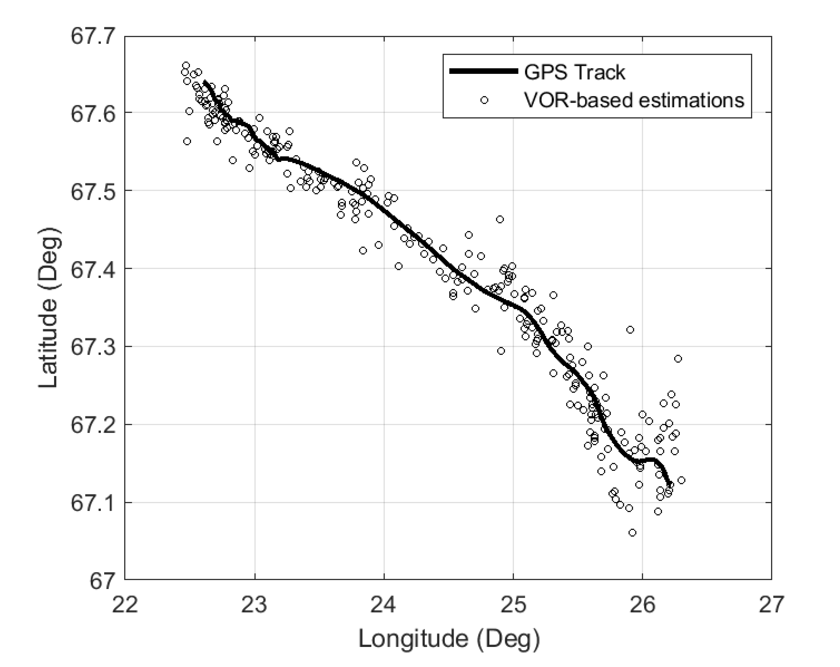
3.2. SDR Data Positioning

The SDR data offered several advantages compared to the COTS receiver:
  • Increased sample rate of the VOR data;
  • Concurrent reception of more than one station;
  • Tunable receiver settings.
These advantages proved decisive for the position estimation–more samples allow for them to be filtered via an average, up to an arbitrarily high precision. The reception of multiple station at the same time on the other hand made it possible to compare the radial reading from different stations at the exact same time, greatly increasing the accuracy.
Contrary to the COTS receiver, it was necessary to demodulate the raw signal during the analysis, but this allowed for the fine tuning of the receiver settings and temperature shift compensation of the local oscillator.
When more than two stations are received, more than one interception point is identified when the radials are combined. It is therefore necessary to combine the information from the different interception points in order to get the position estimation.
It is important to point out how the arrangement of the radials greatly influences the precision of the position measurement: two orthogonal radials produce the most precise measurement, and the precision increases as the distance to the receivers reduces. On the other hand, two parallel radials provide no usable position at all.
As such, different weights can be given to the intersection of different radials in a weighted average calculation for the position estimation. Shown in Figure 4 is an example of the estimation with three VOR stations present. Two High Reliability Points (HRP) are present, while the combination of Station 1 and Station 3, which are almost at 180 degrees from each other, form a Low Reliability Point (LRP); in fact, a small error in the radial of STA1 or STA3 will cause a great movement of the LRP point. The final position estimation is the weighted average of the three points, with the LRP having a low weight.
The weight of each intersection is assigned based on the geometrical properties of the arrangement between the two stations. A small, fixed error of ± δ ϑ is assigned to each the radial reading as shown in Figure 5. The four intersection points define a quadrilateral whose area is used as a measurement quality of the main intersection point–the higher the area, the lower is the reliability and quality of the intersection. Using the area as a measurement of quality is useful for two main reasons: (1) the further the receiver is from the stations the bigger the area for a given radial, so that the reliability decreases with distance, and (2) an interception at low angle of incidence, i.e., with the radials close to parallel, will give an higher area and thus lower reliability. In fact, close-to-parallel radials provide little information on the position, as small errors on the radial translate to a considerable movement of the intersection point.
Intersections with a very low reliability are discarded altogether, with the threshold area being determined experimentally. This was necessary because stations very far away (more than 400 km) only negatively contributed to the position determination.
Using this system, a total of 350 positions were estimated during the stratospheric balloon path, which are shown in Figure 6 compared to the GPS-recorded track.
This method applied to the stratospheric data reaches a mean error of 4.04   km with a standard deviation of 2.76   km —a clear improvement over the COTS receiver—mainly due to the availability of multiple concurrent VOR stations and more measurements. Figure 7 shows the error trend throughout the stratospheric flight, above the SSV.
The importance of multiple stations can be seen in Figure 8 which shows the mean error and the standard deviation of positions estimations depending on the amount of stations that were used in the estimation process. The diminishing return effect is attributed to the fact that the VOR stations are spread out, and a higher number usually means that the additional stations are further away.

4. Discussion

The results from the conducted analysis highlight how VOR-based positioning can be adopted in stratospheric flight to support the GNSS receivers, thus improving the reliability of the on-board navigation and station keeping system for stratospheric missions.
Between the two analyzed sensors, the SDR has been demonstrated as capable of reaching higher accuracy and precision values. The lower performances of the COTS receivers are mainly determined by the data acquisition strategy, forcing to receive radials from one only station at a time, thus allowing to achieve positioning when switching frequencies from one station to the other. On the other hand, the SDR spectrum recording allows to acquire many VOR radial simultaneously, permitting to perform an optimization among the collected radials to achieve more accurate positioning. Although these analyses were performed after the stratospheric flight, an automatic, real-time, data analysis from SDR data can be achieved through airborne computing units and low cost SDRs. Software Defined Radio architectures for stratospheric or even suborbital tracking offer extremely interesting perspectives in terms of ease of implementation, flexibility, and low costs. After STRATONAV, other experiments have been conceived and developed at S5Lab to perform SDR-based tracking of stratospheric balloons. For example, a further experiment developed by S5Lab for the REXUS/BEXUS Programme, named TARDIS (Tracking and Attitude Radio-based Determination In Stratosphere [32]), was aimed at real-time determination of the position and attitude of the BEXUS gondola while in stratospheric flight through SDRs. New concept experiments on innovative tracking systems are the aim of STRAINS (Stratospheric Tracking Innovative Systems, [33]), a new experiment aimed at demonstrating large baseline Time Difference of Arrival (TDOA) for stratospheric and suborbital vehicles, in the perspective of a future implementation for satellite tracking and Space Traffic Management. For the adopted technologies and for their implementation on-board the flight unit, STRATONAV can be considered a precursor of the mentioned new projects that have profited from the lessons learned from this successful experimentation. As for the future applicability of such experimental units, SDRs can be easily implemented on all stratospheric vehicles for real-time navigation purposes: an independent unit with batteries, computing unit and RF hardware can easily present a mass below 0.5 kg and very limited volume occupation (even less than 50 × 100 × 100 mm, as demonstrated for small satellites implementing the same technologies [34]).
If implementing VOR or VOR-based signal processing techniques as secondary navigation method, it shall be remarked how VOR can be available only above land and it finds no applications when overflying the ocean. Although this limitation can anyway fit with several mission profiles (e.g., temporary probing of populated areas or telecommunication links for areas caught by natural disasters), the service cannot be assured worldwide as for the GNSS. Furthermore, the implementation costs of SDR technology for exploitation of radio-navigation systems have a comparable cost to low-cost GNSS receivers on redundant constellations. Finally, some of the NavAids, including VOR, are progressively undergoing discontinuation by some national civil aviation authorities, which can limit the future applications of the investigated system [35], although proposing a promising secondary positioning method.

5. Conclusions

The data from the STRATONAV Experiment, launched in 2016 on a BEXUS stratospheric balloon from the Esrange Space Center in Kiruna, Sweden, have been reprocessed in order to achieve positioning through the intersection of multiple VOR radials. The experiment data collection was made possible through two separate receivers: a commercial receiver able to decode a radial at a time and a SDR recording the entire VOR band spectrum, therefore able to acquire all the VOR signals simultaneously.
The positioning accuracy reached with the re-processing of the VOR data amounts 5.7 km of mean error and 3.29 km of standard deviation, which can be profiting from a limited amount of data due to the single radial data collection strategy, and 4.04 km and 2.76 km of standard deviation for the SDR. The results are acceptable to consider the system a potential, low-cost back-up for high altitude GNSS receivers on stratospheric airships. From the STRATONAV results, further experiments have been started for stratospheric balloons: TARDIS had the aim of achieving real-time positioning and attitude determination through SDRs, while STRAINS uses the same technology for testing long baseline TDOA with stratospheric balloons in the perspective of future suborbital and satellite experimentation.

Author Contributions

Conceptualization, P.M.; methodology, P.M. and L.F.; software, P.M. and L.F.; investigation, P.M. and L.F.; writing—original draft preparation, P.M. and L.F.; writing—review and editing, P.M.; visualization, L.F.; supervision, F.P. and F.S. All authors have read and agreed to the published version of the manuscript.

Funding

The STRATONAV experiment development received funding and support by the following companies: Eggcelerate, Mediasoft, MEGATRON Sensors, and Italian Amateur Radio Association (ARI)–Rome.

Institutional Review Board Statement

Not applicable.

Informed Consent Statement

Not applicable.

Data Availability Statement

Data sharing not applicable.

Acknowledgments

STRATONAV project was part of the REXUS/BEXUS Programme. The REXUS/BEXUS programme is realized under a bilateral Agency Agreement between the German Aerospace Center (DLR) and the Swedish National Space Agency (SNSA). The Swedish share of the payload has been made available to students from other European countries through the collaboration with the European Space Agency (ESA). Experts from DLR, SSC, ZARM and ESA provide technical support to the student teams throughout the project. EuroLaunch, the cooperation between the Esrange Space Center of SSC and the Mobile Rocket Base (MORABA) of DLR, is responsible for the campaign management and operations of the launch vehicles. The publication of this manuscript is provided by the Italian Space Agency in the framework of the Accordo Attuativo ASI 2020-30-HH.0—IKUNS3-SIMBA for the future implementation of the developed radio-frequency technologies on-board nano-satellites.

Conflicts of Interest

The authors declare no conflict of interest.

References

  1. Gonzalo, J.; López, D.; Domínguez, D.; García, A.; Escapa, A. On the Capabilities and Limitations of High Altitude Pseudo-Satellites. Prog. Aerosp. Sci. 2018, 98, 37–56. [Google Scholar] [CrossRef]
  2. Santoro, F.; Del Bianco, A.; Viola, N.; Fusaro, R.; Albino, V.; Binetti, M.; Marzioli, P. Spaceport and Ground Segment Assessment for Enabling Operations of Suborbital Transportation Systems in the Italian Territory. Acta Astronaut. 2018, 152, 396–407. [Google Scholar] [CrossRef]
  3. van Wynsberghe, E.; Turak, A. Station-Keeping of a High-Altitude Balloon with Electric Propulsion and Wireless Power Transmission: A Concept Study. Acta Astronaut. 2016, 128, 616–627. [Google Scholar] [CrossRef]
  4. Konefal, T.; Tozer, T.C.; Thornton, J.; Grace, D.; Spillard, C. Broadband Communications from a High-Altitude Platform: The European HeliNet Programme. Electron. Commun. Eng. J. 2001, 13, 138–144. [Google Scholar] [CrossRef]
  5. Tozer, T.C.; Grace, D. High-Altitude Platforms for Wireless Communications. Electron. Commun. Eng. J. 2001, 13, 127–137. [Google Scholar] [CrossRef] [Green Version]
  6. Alam, M.I.; Pant, R.S. Multi-Objective Multidisciplinary Design Analyses and Optimization of High Altitude Airships. Aerosp. Sci. Technol. 2018, 78, 248–259. [Google Scholar] [CrossRef]
  7. Du, H.; Lv, M.; Zhang, L.; Zhu, W.; Wu, Y.; Li, J. Energy Management Strategy Design and Station-Keeping Strategy Optimization for High Altitude Balloon with Altitude Control System. Aerosp. Sci. Technol. 2019, 93, 105342. [Google Scholar] [CrossRef]
  8. Aragón-Zavala, A.; Cuevas-Ruiz, J.L.; Delgado-Penín, J.A. High-Altitude Platforms for Wireless Communications; Wiley: Chichester, UK, 2008; ISBN 978-0-470-51061-2. [Google Scholar]
  9. Gao, Z.; Ge, M.; Li, Y.; Shen, W.; Zhang, H.; Schuh, H. Railway Irregularity Measuring Using Rauch–Tung–Striebel Smoothed Multi-Sensors Fusion System: Quad-GNSS PPP, IMU, Odometer, and Track Gauge. GPS Solut. 2018, 22, 36. [Google Scholar] [CrossRef]
  10. Liu, W.; Shi, X.; Zhu, F.; Tao, X.; Wang, F. Quality Analysis of Multi-GNSS Raw Observations and a Velocity-Aided Positioning Approach Based on Smartphones. Adv. Space Res. 2019, 63, 2358–2377. [Google Scholar] [CrossRef]
  11. Specht, C.; Weintrit, A.; Specht, M. A History of Maritime Radio-Navigation Positioning Systems Used in Poland. J. Navig. 2016, 69, 468–480. [Google Scholar] [CrossRef] [Green Version]
  12. International Civil Aviation Organization (ICAO). Annex 10—Aeronautical Telecommunications; ICAO: Montréal, QC, Canada, 2001; Volume I. [Google Scholar]
  13. International Civil Aviation Organization (ICAO). Navigation Roadmap; ICAO Workshop on PBN Airspace Redesign and GNSS Implementation Supporting PBN; ICAO: Montréal, QC, Canada, 2012. [Google Scholar]
  14. Anderson, W.G. The Accuracy of the VHF Omni-Range System of Aircraft Navigation; A Statistical Study. IRE Trans. Aeronaut. Navig. Electron. 1955, ANE-2, 25–37. [Google Scholar] [CrossRef]
  15. REXUS. BEXUS Programme Official Website: BEXUS Projects. Available online: http://rexusbexus.net/bexus/ (accessed on 8 August 2021).
  16. Marzioli, P.; Frezza, L.; Curianò, F.; Pellegrino, A.; Gianfermo, A.; Angeletti, F.; Arena, L.; Cardona, T.; Valdatta, M.; Santoni, F.; et al. Experimental Validation of VOR (VHF Omni Range) Navigation System for Stratospheric Flight. Acta Astronaut. 2021, 178, 423–431. [Google Scholar] [CrossRef]
  17. European Organization for Civil Aviation Electronics. EuroCAE ED-52: Minimum Operational Performance Specification (MPS) for Ground Conventional and Doppler Very High Frequency Omni Range (CVOR and DVOR) Equipment; EuroCAE: Saint-Denis, France, 1984. [Google Scholar]
  18. Moir, I.; Seabridge, A.G. Aircraft Systems: Mechanical, Electrical and Avionics Subsystems Integration, 3rd ed.; John Wiley & Sons Inc.: Chichester, UK; Hoboken, NJ, USA, 2008; ISBN 978-0-470-05996-8. [Google Scholar]
  19. Marzioli, P.; Curianò, F.; Pellegrino, A.; Angeletti, F.; Frezza, L.; Gianfermo, A.; Valdatta, M.; Arena, L.; Cardona, T. Testing VOR Performances in the Stratosphere: The STRATONAV Experiment (Paper Code: IAC-16,B2,2,7,X34462). In Proceedings of the 68th International Astronautical Congress, Guadalajara, Mexico, 26–30 September 2016. [Google Scholar]
  20. Pastore, R.; Delfini, A.; Micheli, D.; Vricella, A.; Marchetti, M.; Santoni, F.; Piergentili, F. Carbon Foam Electromagnetic Mm-Wave Absorption in Reverberation Chamber. Carbon 2019, 144, 63–71. [Google Scholar] [CrossRef]
  21. Piattoni, J.; Ceruti, A.; Piergentili, F. Automated Image Analysis for Space Debris Identification and Astrometric Measurements. Acta Astronaut. 2014, 103, 176–184. [Google Scholar] [CrossRef]
  22. Candini, G.P.; Piergentili, F.; Santoni, F. Designing, Manufacturing, and Testing a Self-Contained and Autonomous Nanospacecraft Attitude Control System. J. Aerosp. Eng. 2014, 27, 04014033. [Google Scholar] [CrossRef]
  23. Piergentili, F.; Candini, G.P.; Zannoni, M. Design, Manufacturing, and Test of a Real-Time, Three-Axis Magnetic Field Simulator. IEEE Trans. Aerosp. Electron. Syst. 2011, 47, 1369–1379. [Google Scholar] [CrossRef]
  24. Santoni, F.; Piergentili, F.; Graziani, F. The UNISAT Program: Lessons Learned and Achieved Results. Acta Astronaut. 2009, 65, 54–60. [Google Scholar] [CrossRef]
  25. Santoni, F.; Piergentili, F.; Bulgarelli, F.; Graziani, F. UNISAT-3 Power System. In Proceedings of the European Space Agency, (Special Publication) ESA SP, Stresa, Italy, 9 May 2015; pp. 395–400. [Google Scholar]
  26. Marzioli, P.; Gugliermetti, L.; Santoni, F.; Delfini, A.; Piergentili, F.; Nardi, L.; Metelli, G.; Benvenuto, E.; Massa, S.; Bennici, E. CultCube: Experiments in Autonomous in-Orbit Cultivation on-Board a 12-Units CubeSat Platform. Life Sci. Space Res. 2020, 25, 42–52. [Google Scholar] [CrossRef]
  27. Santoni, F.; Gugliermetti, L.; Piras, G.; De Pascale, S.; Pannico, A.; Piergentili, F.; Marzioli, P.; Frezza, L.; Amadio, D.; Gianfermo, A.; et al. GreenCube: Microgreens Cultivation and Growth Monitoring on-Board a 3U CubeSat. In Proceedings of the 2020 IEEE 7th International Workshop on Metrology for AeroSpace (MetroAeroSpace), Pisa, Italy, 22–24 June 2020; pp. 130–135. [Google Scholar]
  28. ADAFRUIT Adafruit GPS Breakout Datasheet. Available online: https://cdn-learn.adafruit.com/downloads/pdf/adafruit-ultimate-gps.pdf (accessed on 31 August 2021).
  29. Finavia Finland Aeronautical Information Publication (AIP). Available online: https://ais.fi/C-en (accessed on 8 August 2021).
  30. LFV—Swedish National Entity for Flight Assistance Aeronautical Information Publications (AIPs) for Instrumental Flight Rules (IFR) in Sweden. Available online: https://www.aro.lfv.se/ (accessed on 8 August 2021).
  31. AVINOR—Norway National Entity for Flight Assistance Aeronautical Information Publications (AIPs) for Instrumental Flight Rules (IFR) in Norway. Available online: https://www.ippc.no/norway_aip/current/main_en.html (accessed on 8 August 2021).
  32. di Palo, L.; Bandini, V.; Bedetti, E.; Broggi, G.; Collettini, L.; Celesti, P.; Ienno, D.D.; Garofalo, R.; Iovanna, F.; Mattei, G.; et al. Stratospheric Balloon Attitude and Position Determination System Based on the VHF Omnidirectional Range Signal Processing: TARDIS Experiment. In Proceedings of the 2019 IEEE 5th International Workshop on Metrology for AeroSpace (MetroAeroSpace), Rome, Italy, 20–22 June 2019; pp. 607–612. [Google Scholar]
  33. di Palo, L.; Garofalo, R.; Bedetti, E.; Celesti, P.; Iovanna, F.; Frezza, L.; Marzioli, P.; Piergentili, F.; Volpe, A.; Curianò, F.; et al. Time Difference of Arrival for Stratospheric Balloon Tracking: Design and Development of the STRAINS Experiment. In Proceedings of the 2020 IEEE 7th International Workshop on Metrology for AeroSpace (MetroAeroSpace), Pisa, Italy, 22–24 June 2020; pp. 362–366. [Google Scholar]
  34. Frezza, L.; Marzioli, P.; Curianò, F.; Gugliermetti, L.; Amadio, D.; Pirrotta, S.; Kimani, J.N.; Mwita, P.; Mwaniki, C.; Santoni, F. From 1KUNS-PF to WildTrackCube-SIMBA: Strengthening the Cooperation between Italy and Kenya in Nano-Satellite Manufacturing and Operations. In Proceedings of the 71st International Astronautical Congress—The Cyberspace Edition, Held Virtually, 12–14 October 2020. [Google Scholar]
  35. Ken Ward Discontinuation of VOR Service, April 2012. Available online: https://www.faa.gov/air_traffic/flight_info/aeronav/acf/media/Presentations/12-01_Discon-of-VOR-update.pdf (accessed on 14 September 2021).
Figure 1. Comparison between GPS and VOR-based balloon ground track.
Aerospace 08 00263 g001
Figure 2. Error on the ground track determination through the COTS receiver data.
Aerospace 08 00263 g002
Figure 3. GPS (blue) and VOR-based (red) ground tracks displayed on a map (plot A), location map with balloon trajectory in red (plot B).
Aerospace 08 00263 g003
Figure 4. Representation of multiple intersections from three different VOR stations.
Aerospace 08 00263 g004
Figure 5. Geometrical representation of the uncertainty assigned to a particular radial intersection arrangement.
Aerospace 08 00263 g005
Figure 6. VOR-based track from SDR data compared to the GPS track.
Aerospace 08 00263 g006
Figure 7. Error between the VOR-based track and the GPS data.
Aerospace 08 00263 g007
Figure 8. Trend of the mean error and deviation of the position estimation depending on how many VOR stations were used.
Aerospace 08 00263 g008
Publisher’s Note: MDPI stays neutral with regard to jurisdictional claims in published maps and institutional affiliations.

