Abstract
The failure analysis of a non-circular hole with an inclusion layer embedded in an infinite cracked matrix under a remote in-plane uniform load is presented. In this study, a series solution of stress functions for both the matrix and inclusion layer is obtained using the complex variable theory in conjunction with the method of conformal mapping. The stress intensity factor (SIF) can then be determined numerically by solving the singular integral equation (SIE) for the interaction among different crack sites, material properties, and geometries of irregular holes with an inclusion layer. In particular, the failure behavior of composite structures associated with an approximately triangular hole and an approximately square hole with inclusion layers, such as those of oxides, nitrides, and sulfides, is examined in detail. The results demonstrate that a softer layer would enhance the SIF and a stiffer layer would restrain the SIF when a crack is near the inclusion layer. It can be concluded that crack propagation would be suppressed by a stiffer layer even when a micro-defect such as a hole resides in the inclusion layer.
1. Introduction
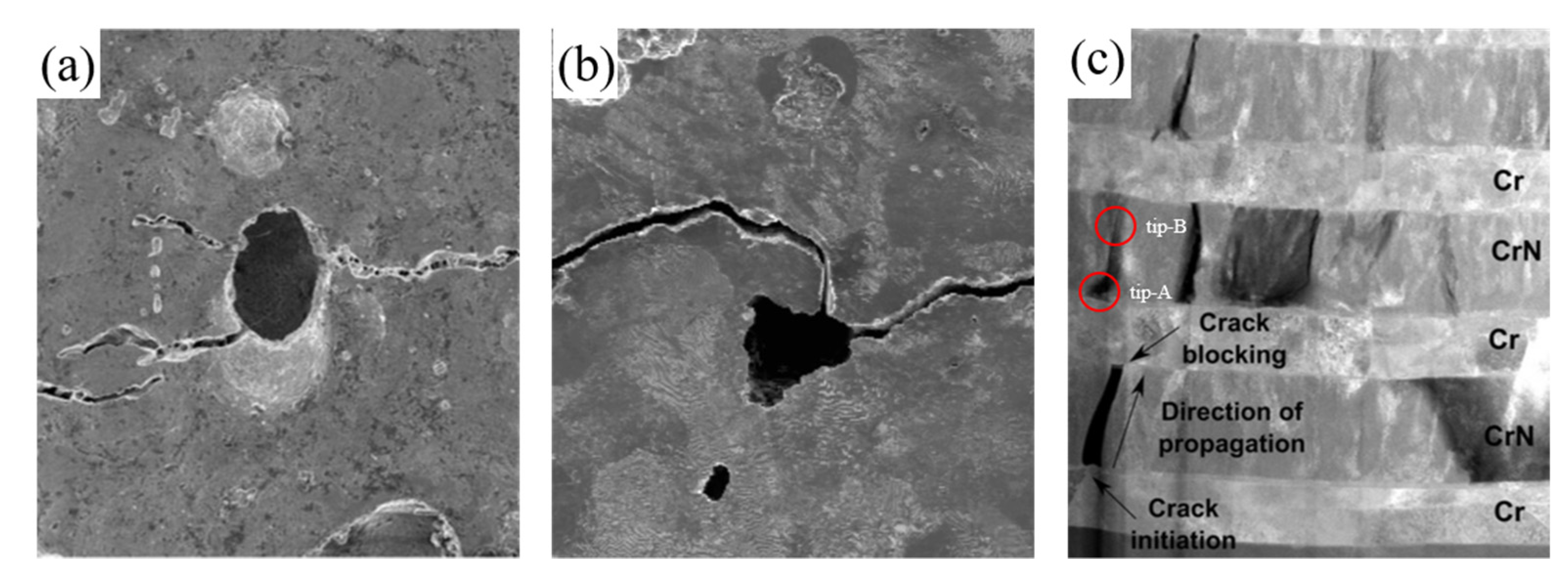
The research on additive and casting manufacturing will inevitably leave a defect in the workpiece. Defects, which include holes, pores, voids, inclusions, particles, pits, and impurities, could become initial fracture sites owing to their hazardous effect on the mechanical strength properties and fatigue strength. Based on experimentally obtained images, defects with different geometries such as circle [1], triangle [2], and arbitrary shape [3] are shown in Figure 1a, Figure 1b, and Figure 2a, respectively. Different defect geometry affects stress concentration and crack propagation differently. Many experiments obtained original results on the crack propagation mechanism. The multilayer coating system is observed wherein the crack existing in CrN would propagate to the next interface Cr/CrN [4] as shown in Figure 1c. For the casting process, pores should exist inside the workpiece. If a crack tip exists near pores subject to a mechanical loading, crack propagation is likely and would be directed toward the pores [2] as shown in Figure 1b. Manganese sulfide (MnS) inclusion would initiate crack evolution because the high interfacial stress around the boundary results in a decrease of the local fracture toughness and hastens the crack propagation [5].
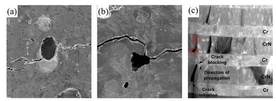
Figure 1.
Micro-defects revealed by scanning electron microscopy (SEM) images (a) Reprinted with permission from Ref. [1]. 2021 The Royal Society, (b) Reprinted from Ref. [2], (c) Reprinted with permission from Ref. [4]. 2021 Elvesier.
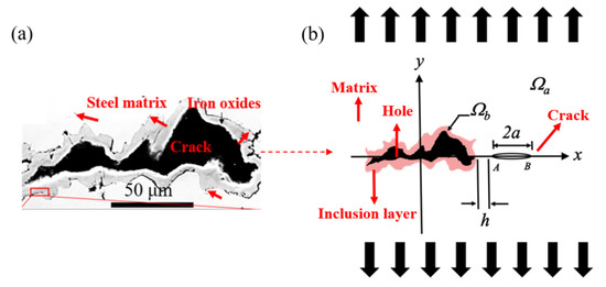
Figure 2.
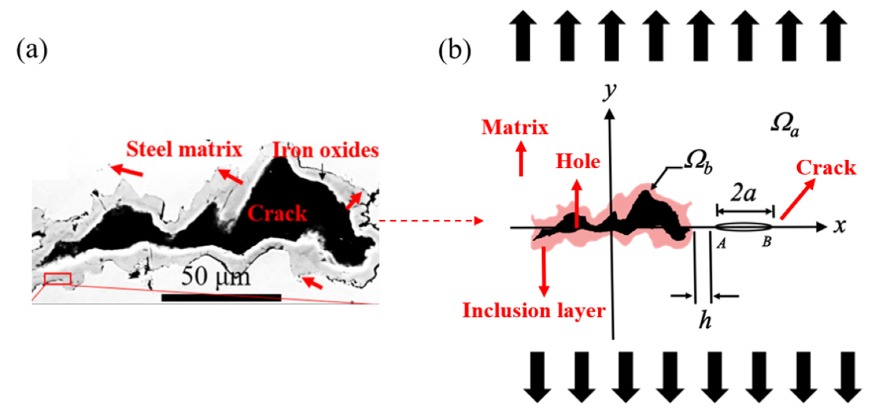
(a) Observation of macrostructure of hole, iron oxide, and steel matrix after the process of whole thermal treatment. Reprinted from Ref. [3]; (b) outlined photograph for illustrating the interaction between a line crack in the steel matrix and an irregular hole with inclusion layer under an in-plane remote uniform tensile loading.
The fundamental studies on failure analysis of circular inclusion have been carried out [6,7,8] based on linear elasticity and complex variable theory [9]. The thermoelastic and elastic problems of an arbitrary hole with a coating layer [10,11,12] or without a coating layer [13,14] have been investigated using the conformal mapping function. To obtain the SIF, the singular integral equation could be employed to perform numerical calculation by addressing a discrete segment of a crack. The superposition for the solution of a homogeneous plate under external loading and the solution of a plate under a dislocation are applied to solve the SIE. Once the equation is established, the SIE could be solved numerically using the Gaussian–Chebyshev method. For a multilayered composite system, both stress and displacement continuity conditions must be forcibly satisfied through analytical continuation. It should be noted that divergent terms would exist in a stress field when analytical continuation and conformal mapping are applied to the irregular hole problem. It becomes tremendously difficult to identify the corrector terms in continuity equations to prevent singularity points, particularly for problems with an irregular inclusion or hole.
The interaction problems between inclusion and crack have been studied extensively by many researchers. For example, the interaction between a crack and a circular inclusion or multiple circular inclusions under anti-plane shear loading has been investigated [15,16,17,18]. The studies indicated that a stiffer inclusion would have a lower SIF. This implies that a stiffer inclusion has a shielding effect on crack propagation [19]. Wikarta observed that the thickness of a coating layer also has a substantial influence on the SIF [20]. It is highly challenging to solve an in-plane crack problem because the number of undermined stress functions is larger than that for the anti-plane problem. The problem of the interaction of an in-plane crack with an elliptical inclusion was investigated by Chen [21]. Chao et al. considered the problem of a crack interacting with a three-phase composite and fibrous composite [22,23,24]. Based on homogenization techniques and failure criteria, Greco et al. investigated the interaction problem between micro-crack and fiber-reinforced composite material [25].
The failure analysis of an irregular hole with an inclusion layer embedded in a cracked matrix is a challenging problem that has not been investigated analytically. The aim of the present study is to analyze the failure of a flawed material with different geometries and elastic mismatch between the inclusion layer and the matrix using the conformal mapping and analytical continuation theorem. To comprehensively examine the theoretical failure analysis, some practical experiments such as steel and titanium matrix are introduced. Initially, a steel matrix subject to a hot cross-wedge-rolled loading wherein an oxide layer would be formed around the hole during the metal composite preparation process [3] as shown in Figure 2a. In this study, the steel matrix with a non-circular geometry of inclusion layer and hole under the tensile loads is considered. However, the effects of heat treatment and time are ignored due to the limitation of the theoretical method. An outlined photograph for illustrating the interaction between a line crack in the steel matrix and irregular holes with inclusion layers under an in-plane remote uniform tensile loading is displayed in Figure 2b. To obtain the solution, in this study, either an approximately triangular hole or an approximately square hole is used to replicate an irregular hole with inclusion layers embedded in an infinite cracked plate using the corresponding mapping function (see Figure 3). Based on the continuation theorem in conjunction with the method of conformal mapping, a series solution of stress functions for a non-circular hole embedded in a cracked matrix with an inclusion layer under a remote uniform load is obtained. Moreover, the Mode-I SIF at the crack tip is determined numerically by solving the singular integration equation for the interaction among different crack sites, material properties, and geometries of irregular holes with inclusion layer. The results of the fracture behavior of an irregular hole with an inclusion layer are presented for different shear moduli and shape factors.
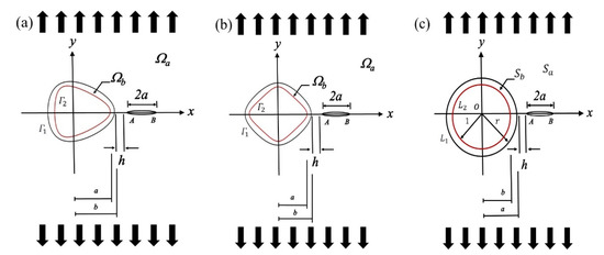
Figure 3.
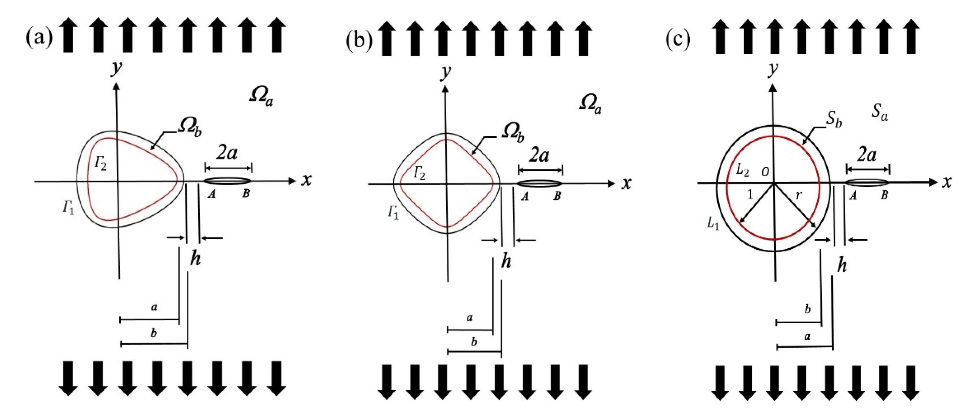
(a) Approximately triangular hole with inclusion layer on physical plane (z-plane); (b) approximately square hole with inclusion layer on physical plane (z-plane); (c) irregular hole with inclusion layer on mathematical plane (ζ-plane).
2. Problem Formulation
The interaction between a line crack in a steel matrix and an irregular hole with an inclusion layer under a remote uniform tensile load is shown in Figure 2b. To simplify this complex problem, an approximately triangular hole and an approximately square hole are used to replicate an irregular hole with an inclusion layer embedded in an infinite cracked plate subject to a remote mechanical tensile load parallel to the y-axis. This is illustrated schematically in Figure 3. Let and represent the matrix and inclusion layer, respectively. The interface between the inclusion layer and the matrix is denoted by , whereas the interface between the inclusion layer and a hole is denoted by (see Figure 3). Note that the inclusion layer is assumed to be perfectly bonded to the matrix and that the hole is under traction-free condition. According to the two-dimensional elasticity theory, the components of the displacement and resultant force in the physical plane (z-plane) can be expressed in terms of the two stress functions and . The mapping function is used as follows to solve an irregular hole problem:
where is the shape factor. The integer represents the number of corners of a hole. For example, , , and for a triangle, square, and pentagon, respectively. The conformal mapping function can map an irregular hole with an inclusion layer in the -plane as shown in Figure 3a,b, onto two circles with a common origin. In addition, the inner and outer radii are unity and r, respectively, in the -plane (see Figure 3c). In the -plane, and represent the matrix and inclusion layer, respectively. represents the interface between these, and represents the interface between and a hole (see Figure 3c). The geometric configurations of an approximately triangular hole with an inclusion layer () and an approximately square hole with an inclusion layer () for different values of are shown in Figure 4 and Figure 5, respectively.

Figure 4.
Configuration of approximately triangular holes with different shape factors.

Figure 5.
Configuration of approximately square holes with different shape factors.
The components of the displacement, resultant force, and stress can be defined as follows:
where is the shear modulus. for the plane stress condition, and for the plane strain condition. is Poisson’s ratio. The prime symbol () represents the derivative with respect to , and the bar () denotes the complex conjugate.
3. Stress Field
To simplify the derivation process, we introduce an auxiliary stress function as follows:
where is the radius of a mapped circle of an inclusion layer.
3.1. Homogeneous Solution
The homogeneous solutions of an isotropic infinite plate under a remote tensile load at an inclined angle between the x-axis and direction of tensile loading can be given as [9]:
3.2. Stress Functions for the Triangular and Square Hole with Inclusion Layer
To solve the two-phase composite system, the stress functions are assumed to be of the following forms:
With regard to an approximately triangular hole with an inclusion layer, the mapping function in Equation (1) becomes:
The homogenous solutions for the problem of an approximately triangular hole with an inclusion layer under an edge dislocation at can be obtained as follows using the above mapping function:
where
and . and are the components of the Burgers vector for the dislocation.
The analytical continuation would be used to determine the remaining stress functions in Equations (9) and (10). First, the stress functions at the interface need to satisfy the perfectly bonded condition such that both resultant force and displacement must be continuous at . Second, the traction-free condition must be satisfied at the hole boundary . After performing the analytical continuation in conjunction with the alternation method, the final expressions of the stress functions for the problem of an approximately triangular hole with an inclusion layer under an edge dislocation at can be obtained as follows:
where
It should be noted that the corrected terms in Equations (19)–(23) should be introduced to remove singularity points. The coefficients of the corrected terms in Equations (19)–(23) are (see Appendix A).
With regard to an approximately square hole with an inclusion layer, the mapping function in Equation (1) becomes:
The homogenous solution pertaining to the problem of an approximately square hole with an inclusion layer under an edge dislocation at can be obtained as follows:
The analytical continuation would be used to determine the remaining stress functions in Equations (9) and (10). Similar to the previous approach, the final expressions of the stress functions for the problem of a square hole with an inclusion layer under an edge dislocation at can be obtained as follows:
where
The coefficients of the corrected terms in Equations (31)–(36) are obtained as (see Appendix A).
It should be noted that the stress functions of an irregular hole with can be obtained in a similar manner. Owing to the limitation of space, only the stress functions with associated with an approximately triangular hole and the stress functions with associated with an approximately square hole are presented.
4. Singular Integral Equations
Consider a crack in an infinite matrix where the corresponding complex potentials are given by
The resultant force along the crack surface can be calculated by substituting and from Equations (37) and (38) into Equation (5) and integrating along the crack surface. The singular integral equation with logarithmic kernels can be obtained as follows by employing the superposition method:
where
with ,, and ,, are the coefficients of and , respectively, from Equations (42)–(44).
For the problem of an infinite matrix under a remote uniform tensile load, the resultant force can be calculated by substituting the homogeneous solution from Equations (7) and (8) into Equations (22) and (23) as well as Equations (35) and (36) for an approximately triangular hole and approximately square hole, respectively:
The single-value condition of the dislocation density function along the crack border must be satisfied such that:
By separating the singular integral equation (Equation (39)) into real and imaginary parts, we obtain the following two singular integral equations:
The coefficients of the dislocation density function can then be solved numerically by Equations (45)–(48).
5. Stress Intensity Factors
To determine the coefficients of the dislocation density function , we divide the crack into N line segments. The crack surface is composed of three parts: left tip, middle segments, and right tip. To approximate the singular solution of the dislocation density function along the crack, the dislocation density function at the right and left tips should be treated as a square-root singularity, whereas the dislocation density function along the middle segments would be considered as a linear interpolation relationship. The formulations of the dislocation density function in terms of the local coordinate system are defined as follows [26]:
where , is the coefficient of the dislocation density function, and represents half of the length of each line segment. algebraic equations are established for solving coefficients of the dislocation density function by substituting the above relationship of the dislocation density function into the singular integral Equations (47) and (48) and satisfying the single-value condition Equation (46). Certain exact integration formulae are used to solve a system of algebraic equations [26]:
and the Gauss–Chebyshev integration rule is used:
After obtaining the coefficients of the dislocation density function, the stress intensity factors can be determined as follows [26]:
where . The inclined angle is defined as the angle between the x-axis and the direction of the tensile load.
6. Results
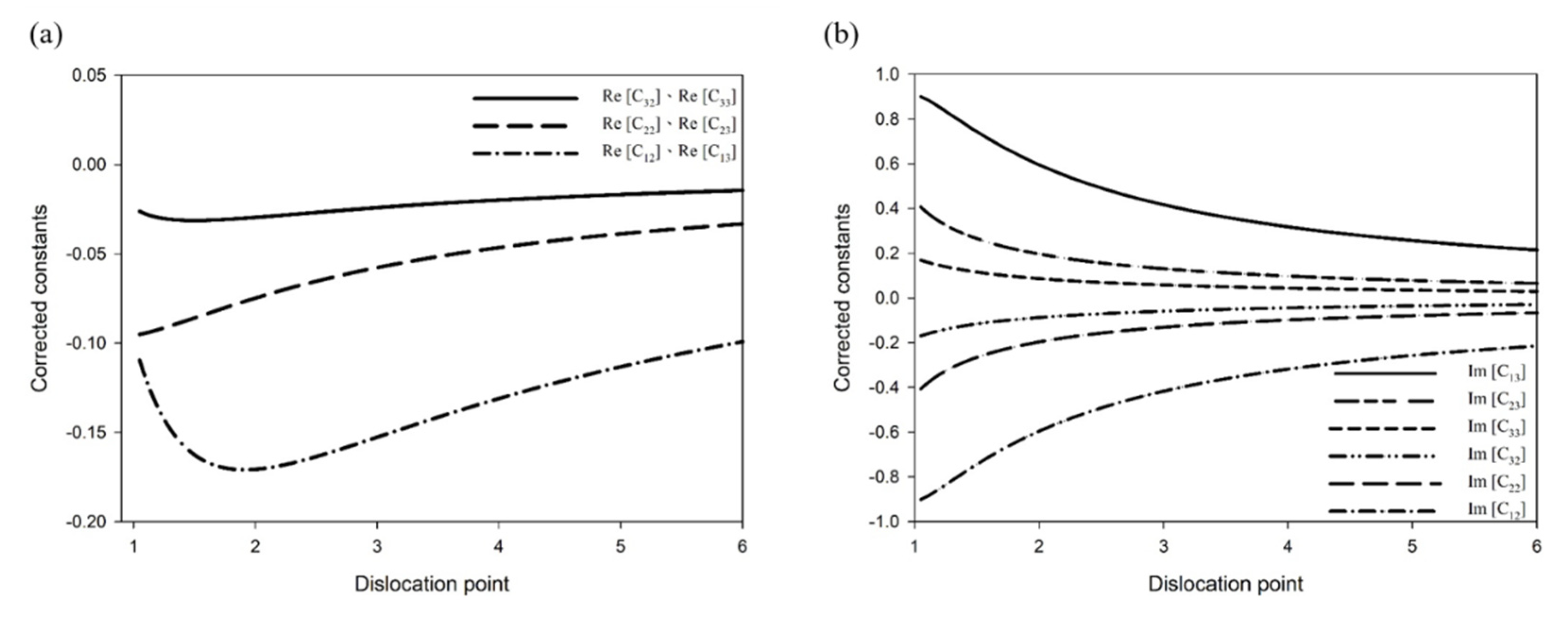
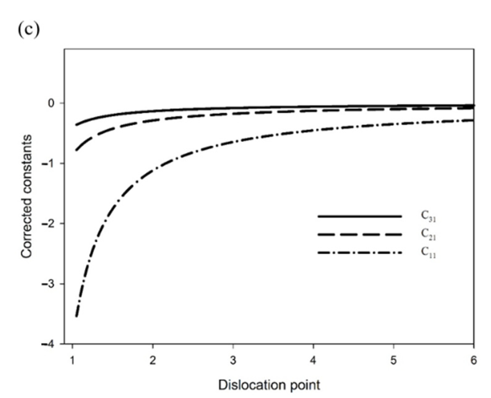
This study is aimed at investigating the failure behavior of a non-circular hole with an inclusion layer embedded in an infinite crack matrix under an in-plane remote uniform load. The SIF depends on the distance between a crack and the non-circular hole with an inclusion layer, material properties, and geometry of the non-circular hole. To prevent certain singular points in the continuity equations, the corrected terms, Equations (A6) and (A10), should be introduced. The contribution of these corrected terms is displayed in Figure 6.
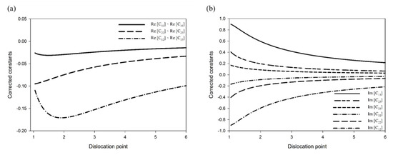
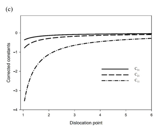
Figure 6.
(a) Real parts of the constants ( and ); (b) imaginary parts of the constants ( and ); (c) constants () for a triangular hole problem (w = 0.15, Gb/Ga = 2, r = 1.05).
Note that the coefficient of the corrected term is a real number and those of the corrected terms and are two conjugate complex numbers. It is noteworthy that the coefficients gradually decrease to zero when the distance between the dislocation and the non-circular hole increases, as shown in Figure 6. Furthermore, the contribution of the corrected terms reduces with the increasing number of iterations, as shown in Table 1. According to this Table, the contribution of the corrected terms from the first to third iterations for a triangular hole problem is 72.7%, 18.7%, and 8.6%, respectively. The first two terms contribute >90%, which shows the rapid convergence of the proposed method.

Table 1.
Value of corrected constant () and its contribution for a triangular hole problem.
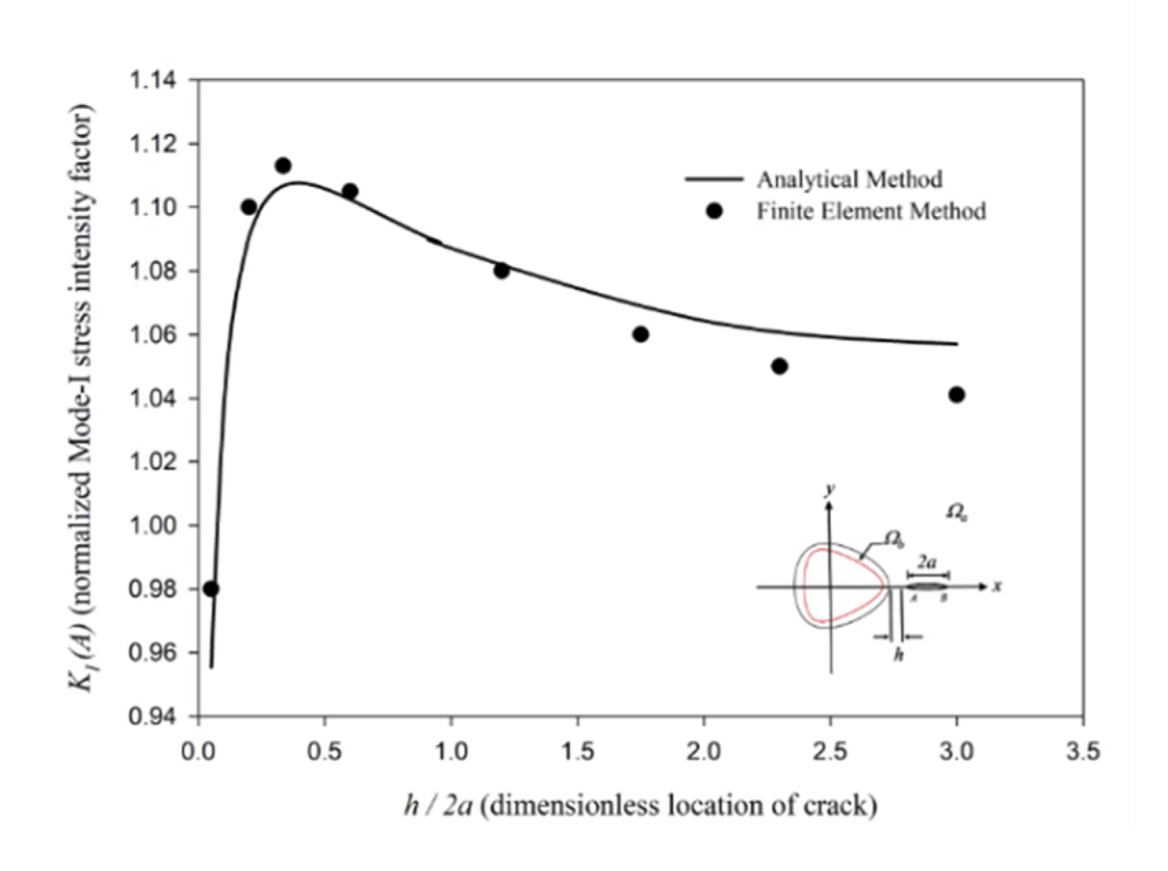
In the first part of this section, an approximately triangular hole with an inclusion layer (n = 2) and a line crack () is considered. To verify the correctness of the presented analytical results, the calculated stress intensity factors at Tip A for an approximately triangular hole problem are compared with the results obtained using the finite element method, as shown in Figure 7. The analytical solutions of the SIF agree well with the results obtained using the finite element method.
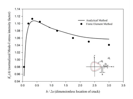
Figure 7.
Stress intensity factors at Tip A for an approximately triangular hole with inclusion layer (w = 0.1, Gb/Ga = 4, r = 1.05).
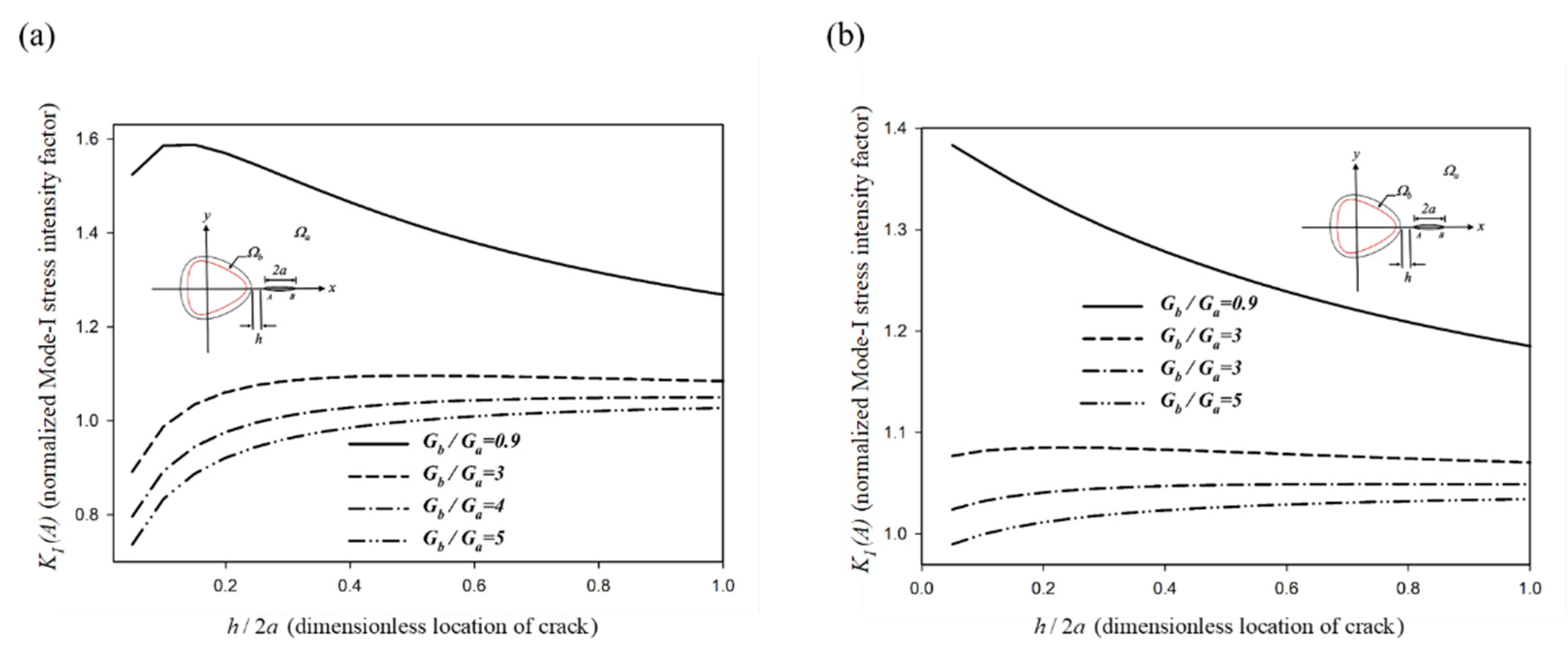
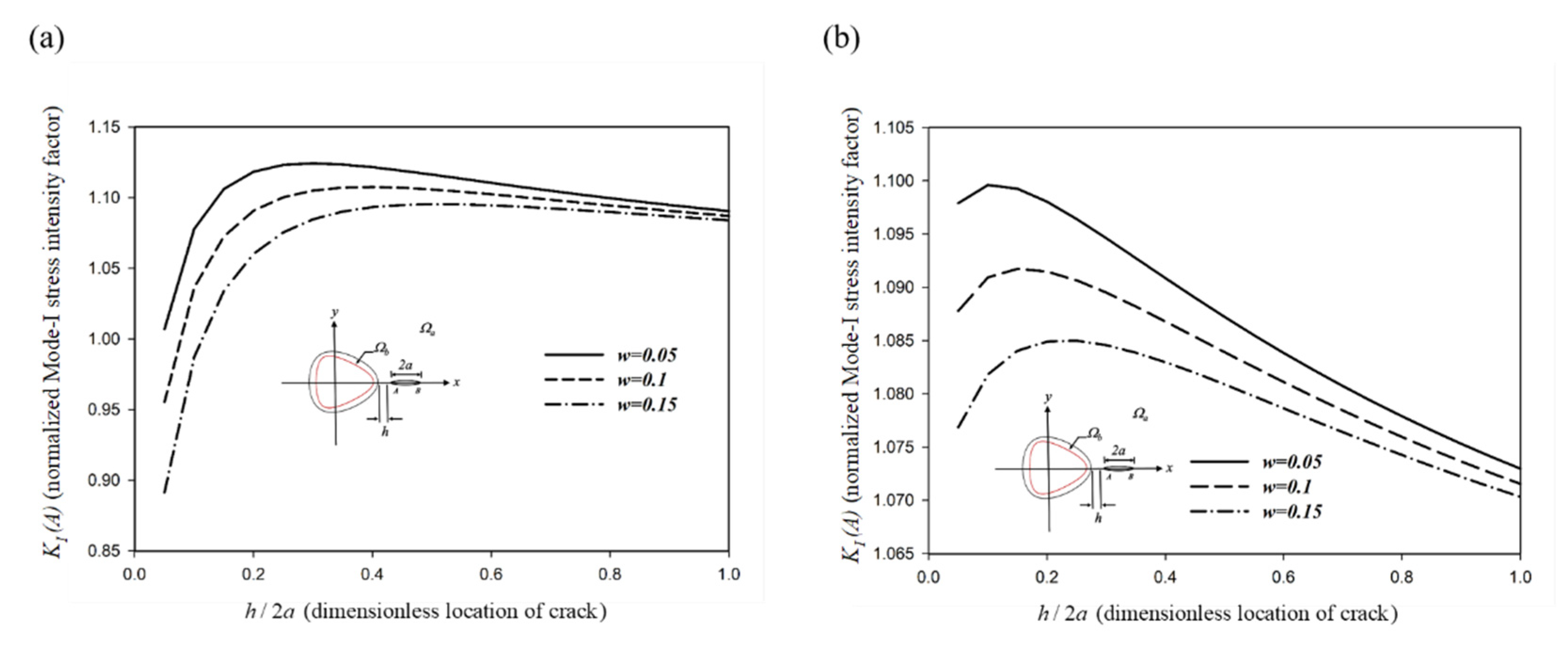
The dimensionless Mode-I SIFs at Tip A and Tip B versus the dimensionless h/2a with different material properties are shown in Figure 8.
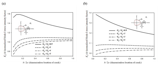
Figure 8.
SIFs with different shear moduli of an approximately triangular hole with inclusion layer (a) at Tip A (b) at Tip B (r = 1.05, w = 0.15).
The results show that the contribution of the inclusion layer becomes significant when the crack and inclusion layer approach each other. In addition, the stiffer inclusion (Gb/Ga = 4, 3, 2) layer would decrease the SIF when the crack approaches the inclusion layer. In contrast, the softer inclusion layer (Gb/Ga = 0.9) would increase the SIF when the crack approaches the inclusion layer, except when the crack is sufficiently close to the inclusion layer. This can be explained by the fact that the presence of the inclusion layer could suppress the crack propagation when the crack tip is adequately close to the inclusion layer. In general, crack propagation would be enhanced when the crack is close to the softer inclusion layer and suppressed when it is close to the stiffer inclusion layer. The Mode-I SIF at Tip B is less affected by the inclusion layer than that at Tip A. This is because the distance between Tip B and a triangular hole is larger than that between Tip A and a triangular hole. It is noteworthy that the softer inclusion (Gb/Ga = 0.9) could decrease the SIF at Tip A when a crack is adequately close to the hole as mentioned above. Meanwhile, the softer inclusion (Gb/Ga = 0.9) increases the SIF at Tip B when the crack approaches a hole. From the experimental observation regarding the evolution of Cr/CrN multilayer coatings on the titanium Ti6Al4V alloy during indentation [4], it is determined that the cracks exist only in the CrN layers after the indentation test (see Figure 1c). The micro-crack initiates at the interface Cr/CrN and grows toward the CrN layer. This is because the shear modulus of Cr and CrN is 115 GPa and 76.6 GPa, respectively [27]. This indicates that the Cr and CrN could be regarded as the stiffer and softer inclusion layer, respectively. This phenomenon demonstrates that crack propagation occurs in the region of the CrN inclusion layer (softer), whereas the Cr inclusion layer (stiffer) can be regarded as a blocking layer to suppress the crack propagation (see Figure 1c). A similar phenomenon of failure behavior can also be observed in the thermal barrier coatings produced after hot corrosion [28]. When the crack is farther from a triangular hole with increasing the distance h/2a, the contribution of the triangular hole to the SIF reduces [29].
The stiffer inclusion layer would exert a retardation effect on crack propagation. The retardation effect can be explained by the trapping mechanism of the dislocation problem. For the interaction problem associated with a coated approximately triangular hole under an edge dislocation [10], the dislocation would be initially attracted by a hole and then repelled by the stiffer coating layer when an edge dislocation approaches the stiffer coating layer. This is the so-called trapping mechanism.
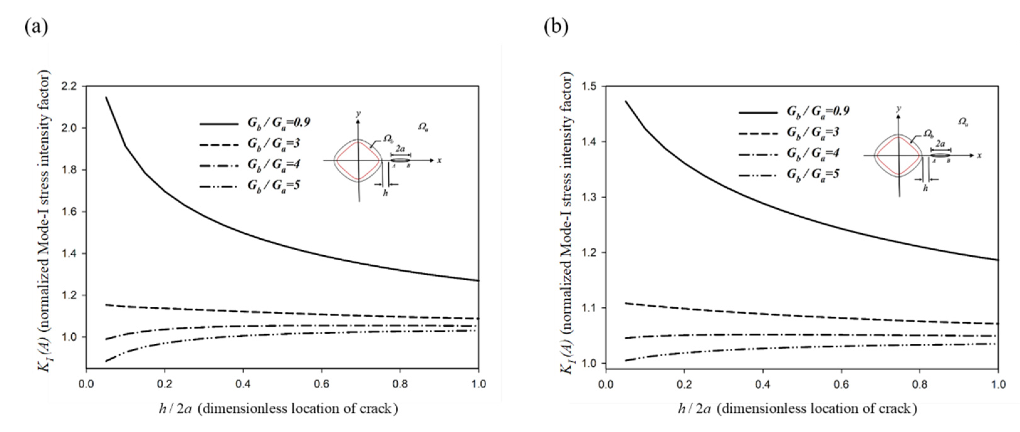
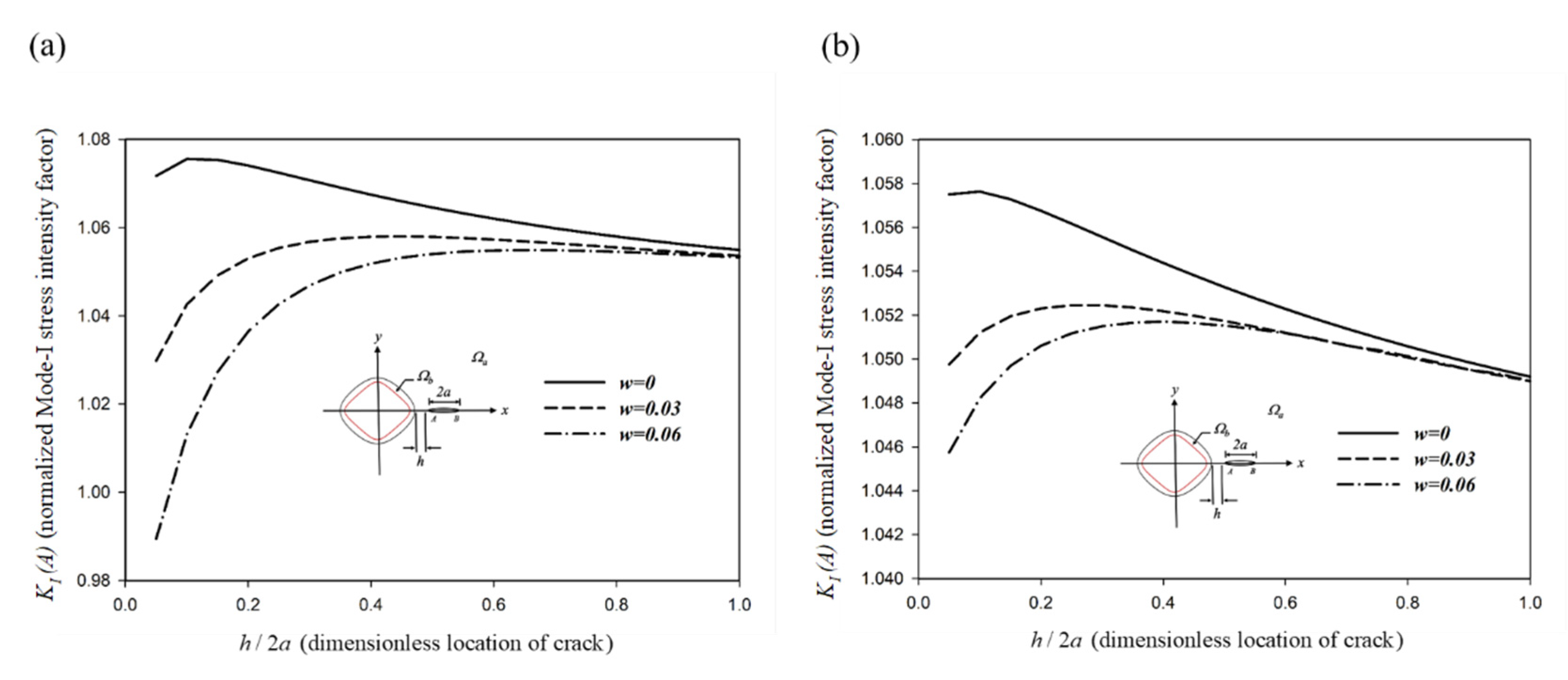
In the second part, an approximately square hole having an inclusion layer with n = 3 in Equation (1) is considered. The dimensionless Mode-I SIFs at Tip A and Tip B versus the dimensionless h/2a with different material properties are shown in Figure 9.
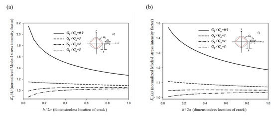
Figure 9.
The SIFs with different shear moduli of an approximately square hole with inclusion layer (a) at Tip A (b) at Tip B (r = 1.05, w = 0.06).
The Mode-I SIF of an approximately square hole with an inclusion layer has a tendency similar to that of an approximately triangular hole with an inclusion layer, as shown in Figure 8. The softer inclusion layer would increase the SIF when the crack is in front of the inclusion layer whereas the stiffer inclusion layer would decrease the SIF. Thus, the stiffer inclusion layer can restrict the crack propagation and generate a retardation effect. In the second section, different configurations of an irregular hole with an inclusion layer obtained by controlling the shape factor are shown in Figure 4 and Figure 5. The effect of the shape factor on the SIF for an approximately triangular hole with a stiffer inclusion layer is shown in Figure 10. The result indicates that the retardation mechanism is stronger for an approximately triangular hole with a stiffer inclusion layer when the shape factor is larger. This is because the inclusion layer becomes shaper when the shape factor increases.
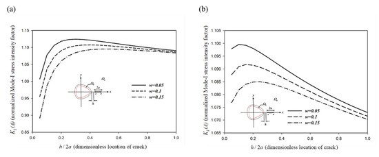
Figure 10.
SIFs with different shape factors of an approximately triangular hole with an inclusion layer (a) at Tip A (b) at Tip B (r = 1.05, Gb/Ga = 4).
Similar results are observed for an approximately square hole with a stiffer inclusion layer as shown in Figure 11. In this study, an approximately triangular hole with an inclusion layer (n = 2) and an approximately square hole with an inclusion layer (n = 3) are demonstrated as representations of an irregular hole with an inclusion layer. From these two cases, both an approximately triangular hole and an approximately square hole, with stiffer inclusion layers would exert a retardation effect on crack propagation depending on the shape factor and material properties.
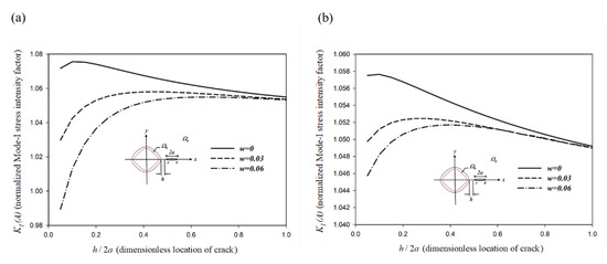
Figure 11.
SIFs with different shape factors of an approximately square hole with an inclusion layer (a) at Tip A (b) at Tip B (r = 1.05, Gb/Ga = 4).
7. Conclusions
The failure analysis of an interaction problem of a non-circular hole with an inclusion layer embedded in an infinite crack matrix under a remote in-plane uniform load is presented in this study. The solution to the stress functions that are holomorphic in different regions is derived in a series form by the conformal mapping method and analytical continuation with an alternating method. Based on the superposition method, a system of singular integral equations is established. Furthermore, the coefficients of the dislocation density functions are obtained numerically and can be related to the SIFs. The theoretical results have a good agreement with the simulation method. In addition, the fracture behavior of the crack is strongly influenced by a non-circular hole when the crack is far away from the non-circular inclusion layer, whereas the contribution of the non-circular inclusion layer becomes more significant when the crack and non-circular inclusion layer approach each other. Owing to the larger shape factor, the effect of geometry would be more intensified. In addition, the corrected terms and SIF would be rapidly convergent when the number of iterations becomes larger. It is important to note that crack propagation would be prevented by the stiffer inclusion layer even when a defect such as a hole resides in the inclusion layer.
Author Contributions
Conceptualization, C.C. (Chingkong Chao) and S.T.; methodology, C.C. (Chenchun Chiu) and S.T.; software, C.C. (Chenchun Chiu), J.G. and S.T.; formal analysis, C.C. (Chenchun Chiu), J.G. and S.T.; investigation, S.T.; resources, C.C. (Chenchun Chiu); data curation, C.C. (Chenchun Chiu) and S.T.; writing—original draft preparation, C.C. (Chenchun Chiu) and S.T.; writing—review and editing, C.C. (Chingkong Chao) and S.T.; visualization, C.C. (Chenchun Chiu) and S.T.; project administration, C.C. (Chingkong Chao). All authors have read and agreed to the published version of the manuscript.
Funding
This research received no external funding.
Institutional Review Board Statement
Not applicable.
Informed Consent Statement
Not applicable.
Data Availability Statement
The data presented in this study are available on request from the corresponding author after obtaining permission from the authorized individual.
Acknowledgments
The research was supported by the Ministry of Science and Technology of Taiwan under the grant MOST 106-2221-E-011-023-MY3.
Conflicts of Interest
The authors declare that they have no known competing financial interests or personal relationships that could have appeared to influence the work reported in this paper.
Appendix A. Determination of Corrected Constants
The potential function in Equation (21) contains certain divergent terms owing to the presence of the mapping function as follows:
For an approximately triangular hole,
For an approximately square hole,
When continuity conditions are employed, three singular terms in for an approximately triangular hole problem and four singular terms in for an approximately square hole problem are observed in Equations (A4) and (A5), respectively:
To remove these singular terms, three corrected constants (, , and ) for an approximately triangular hole case and four corrected constants (, , , and ) for an approximately square hole case are introduced as follows:
For an approximately triangular hole,
where
For an approximately square hole,
where
References
- Turnbull, A. Corrosion pitting and environmentally assisted small crack growth. Proc. R. Soc. A Math. Phys. Eng. Sci. 2014, 470, 20140254. [Google Scholar] [CrossRef]
- Nový, F.; Kopas, P.; Bokůvka, O.; Jambor, M.; Trško, L. Influence of microscopic casting defects on fatigue endurance of ductile cast iron. MATEC Web Conf. 2018, 157, 05019. [Google Scholar] [CrossRef]
- Zhou, X.; Shao, Z.; Tian, F.; Hopper, C.; Jiang, J. Microstructural effects on central crack formation in hot cross-wedge-rolled high-strength steel parts. J. Mater. Sci. 2020, 55, 9608–9622. [Google Scholar] [CrossRef]
- Wieciński, P.; Smolik, J.; Garbacz, H.; Kurzydłowski, K. Failure and deformation mechanisms during indentation in nanostructured Cr/CrN multilayer coatings. Surf. Coat. Technol. 2014, 240, 23–31. [Google Scholar] [CrossRef]
- Mohtadi-Bonab, M.A.; Eskandari, M.; Sanayei, M.; Das, S. Microstructural aspects of intergranular and transgranular crack propagation in an API X65 steel pipeline related to fatigue failure. Eng. Fail. Anal. 2018, 94, 214–225. [Google Scholar] [CrossRef]
- Erdogan, F.; Gupta, G. The stress analysis of multi-layered composites with a flaw. Int. J. Solids Struct. 1971, 7, 39–61. [Google Scholar] [CrossRef]
- Chao, C.K.; Chen, F.M.; Shen, M.H. Circularly cylindrical layered media in plane elasticity. Int. J. Solids Struct. 2006, 43, 4739–4756. [Google Scholar] [CrossRef][Green Version]
- Pak, Y.E.; Mishra, D.; Yoo, S.-H. Closed-form solution for a coated circular inclusion under uniaxial tension. Acta Mech. 2012, 223, 937–951. [Google Scholar] [CrossRef]
- England, A.H. Complex Variable Methods in Elasticity; Courier Corporation: Chelmsford, MA, USA, 2003. [Google Scholar]
- Tseng, S.C.; Chao, C.K.; Chen, F.M. Stress field for a coated triangle-like hole problem in plane elasticity. J. Mech. 2020, 36, 55–72. [Google Scholar] [CrossRef]
- Tseng, S.C.; Chao, C.K.; Chen, F.M. Interfacial stresses of a coated square hole induced by a remote uniform heat flow. Int. J. Appl. Mech. 2020, 12, 2050063. [Google Scholar] [CrossRef]
- Tseng, S.C.; Chao, C.K.; Chen, F.M.; Chiu, W.C. Interfacial stresses of a coated polygonal hole subject to a point heat source. J. Therm. Stresses 2020, 43, 1487–1512. [Google Scholar] [CrossRef]
- Jafari, M.; Nazari, M.B.; Taherinasab, A. Thermal stress analysis in metallic plates with a non-circular hole subjected to uniform heat flux. Eur. J. Mech.-A/Solids 2016, 59, 356–363. [Google Scholar] [CrossRef]
- Jafari, M. Thermal stress analysis of orthotropic plate containing a rectangular hole using complex variable method. Eur. J. Mech.-A/Solids 2019, 73, 212–223. [Google Scholar] [CrossRef]
- Theocaris, P.; Demakos, C. Antiplane shear crack in an infinite plate with a circular inclusion. Ing.-Arch. 1985, 55, 295–306. [Google Scholar] [CrossRef]
- Chao, C.K.; Young, C.W. On the general treatment of multiple inclusions in antiplane elastostatics. Int. J. Solids Struct. 1998, 35, 3573–3593. [Google Scholar] [CrossRef]
- Chao, C.K.; Wikarta, A.; Korsunsky, A. Anti-plane interaction of a crack and reinforced elliptic hole in an infinite matrix. Theor. Appl. Fract. Mech. 2010, 53, 205–210. [Google Scholar] [CrossRef]
- Chao, C.K.; Tseng, S.C.; Chen, F.M. Mode-III stress intensity factors for two circular inclusions subject to a remote uniform shear load. J. Chin. Inst. Eng. 2018, 41, 590–602. [Google Scholar] [CrossRef]
- Park, P.; Sudak, L. Stress intensity factor for an interphase Griffith crack interacting with two imperfect interfaces. Math. Mech. Solids 2010, 15, 353–367. [Google Scholar] [CrossRef]
- Wikarta, A. Anti-plane interaction of a coated circular inclusion with a crack located in matrix. In Applied Mechanics and Materials; Trans Tech Publications Ltd.: Freienbach, Switzerland, 2016; Volume 836, pp. 26–30. [Google Scholar] [CrossRef]
- Chen, D.-H. The effect of an elliptical inclusion on a crack. Int. J. Fract. 1997, 85, 351–364. [Google Scholar] [CrossRef]
- Chao, C.K.; Chen, F.M.; Lin, T.H. Stress intensity factors for fibrous composite with a crack embedded in an infinite matrix under a remote uniform load. Eng. Fract. Mech. 2017, 179, 294–313. [Google Scholar] [CrossRef]
- Chao, C.K.; Wikarta, A. Solutions of a crack interacting with tri-material composite in plane elasticity. CMES-Comput. Model. Eng. Sci. 2013, 93, 167–186. [Google Scholar] [CrossRef]
- Chao, C.K.; Wikarta, A. Solutions of a crack interacting with a three-phase composite in plane elasticity. Appl. Math. Model. 2016, 40, 2454–2472. [Google Scholar] [CrossRef]
- Greco, F.; Leonetti, L.; Blasi, P.N. Non-linear macroscopic response of fiber-reinforced composite materials due to initiation and propagation of interface cracks. Eng. Fract. Mech. 2012, 80, 92–113. [Google Scholar] [CrossRef]
- Cheung, Y.; Chen, Y. New integral equation for plane elasticity crack problems. Theor. Appl. Fract. Mech. 1987, 7, 177–184. [Google Scholar] [CrossRef]
- Chen, H.Y.; Tsai, C.J.; Lu, F.-H. The Young’s modulus of chromium nitride films. Surf. Coat. Technol. 2004, 184, 69–73. [Google Scholar] [CrossRef]
- Kaplan, M.; Uyaner, M.; Ozgurluk, Y.; Doleker, K.M.; Karaoglanli, A.C. Evaluation of hot corrosion behavior of APS and HVOF sprayed thermal barrier coatings (TBCs) exposed to molten Na2SO4 + V2O5 salt at 1000 °C. In Engineering Design Applications; Springer: Berlin/Heidelberg, Germany, 2019; pp. 441–459. [Google Scholar] [CrossRef]
- Tseng, S.C.; Chao, C.K.; Guo, J.Y. Failure analysis of a polygonal void with an oxide layer in a cracked matrix. Int. J. Appl. Mech. 2021, 13, 2150099. [Google Scholar] [CrossRef]
Publisher’s Note: MDPI stays neutral with regard to jurisdictional claims in published maps and institutional affiliations. |
© 2021 by the authors. Licensee MDPI, Basel, Switzerland. This article is an open access article distributed under the terms and conditions of the Creative Commons Attribution (CC BY) license (https://creativecommons.org/licenses/by/4.0/).

