Article

Adaptive Control System Design and Experiment Study of Gas Flow Regulation System for Variable Flow Ducted Rockets

School of Aeronautics and Astronautics, Sun Yat-sen University, Shenzhen 518107, China
*
Author to whom correspondence should be addressed.
Aerospace 2022, 9(10), 595; https://doi.org/10.3390/aerospace9100595
Submission received: 11 September 2022 / Revised: 6 October 2022 / Accepted: 10 October 2022 / Published: 12 October 2022
(This article belongs to the Section Aeronautics)

Abstract

:
Variable flow ducted rockets (VFDRs) are promising candidates for propulsion systems in hypersonic vehicles because of their inherent advantages, such as high specific impulse, low weight, and high speed. The control of gas flow is essential for optimal VFDRs performance. However, the characteristics of gas flow regulation systems, such as anti-regulation, non-linearity, and parameter variation, make it difficult to construct gas flow controllers. Aiming at the above problems, we propose a compound control strategy integrating a novel second-order fuzzy adaptive tracking differentiator (SOA-TD) and an intelligent proportional-integral controller based on adaptive neuro-fuzzy inference system (ANFIS). First, a mathematical model of a gas flow regulation system was developed to analyze the control characteristics of VFDRs. Next, an ANFIS-based proportional-integral controller to developed to respond to the system’s time-varying characteristics. In addition, a novel SOA-TD was constructed to optimize the “arrange transient process” of instructions, which effectively suppressed anti-regulation of the gas flow without increasing response time. Finally, a hardware in loop (HIL) simulation device for VFDRs was established, and serial HIL simulation tests were carried out to verify the validation of the controller. The HIL simulation results indicate that our strategy exhibited a superior performance compared to traditional controllers in terms of adaptability, ability to suppress anti-regulation, and robustness, which is hoped to fulfill VFDRs’ thrust control requirements for a wide range of altitudes and Mach numbers in future engineering applications.

1. Introduction

Variable flow ducted rockets (VFDRs) are considered to be ideal propulsion systems for hypersonic vehicles because of their inherent advantages, such as low weight, high specific impulse, and extended range [1,2,3]. Interest in VFDRs’ gas flow control research has been increasing during the past three decades because of its beneficial effects on the performance improvement of the thrust system [4,5,6,7]. Alan et al. [8,9] established a pressure controller of gas regulating systems by using a model-referenced adaptive control strategy and verified the performance of the proposed controller via simulations with cold gas and air. To overcome the trade-off between rapid response and gas control system undershoot, Zhou et al. [10] developed a neural network PID controller with back propagation. Using linear matrix inequality, Niu et al. [11] implemented a proportional-integral control system for gas generators and tested its effectiveness experimentally. To satisfy the design constraints and variable parameter characteristics of the gas flow control system, Wang et al. [12] designed an RBFNN-based controller and verified its effectiveness by hardware-in-loop (HIL) simulation. Chang et al. [13] developed a model that integrated a gas flow regulating system, a servo system, a VFDRs engine, and a new feedback variable, eliminating the trade-off between stability and rapid response.
Due to VFDRs’ inherent properties and harsh operating conditions, there are various security constraints, including the inlet unstart boundary, the combustor temperature limitation, and material strength limitation. Hence, safety protection also plays a significant role in the design of gas flow control systems. In an earlier study, Shi et al. [14] discussed the inlet buzz boundary and margin of VFDRs and designed an active buzz margin controller. Bao et al. [15] developed a min/max switching strategy for thrust/protection control. By selecting the minimum control signal of the thrust controller and inlet buzz protection controller, the control system could be switched to guarantee VFDRs against crossing the inlet buzz boundary. Qi et al. [16] designed a multi-objective robust controller for a class of scramjet engines to guarantee the output tracking requirement of safety protection by using guaranteed cost and regional pole placement techniques.
In addition, most of the above studies only focused on the gas flow regulation response characteristics and safety performance, but not enough attention was paid to the anti-regulation characteristics of VFDRs. Wilkerson et al. [17] pointed out that the gas regulating system of a VFDR is a typical non-minimum phase system with anti-regulation characteristics [18,19]. The anti-regulation characteristics refer to the fact that “if the gas flow rate is increased by decreasing the throat area, the actual gas flow drops at first before turning to increase to the expected value and vice versa”. Anti-regulation of the gas flow results in changes in combustion chamber pressure and thrust, putting the inlet in a subcritical state and potentially endangering VFDRs’ stability. Chai et al. [20] introduced a tracking differentiator (TD) into the gas flow control system to arrange a rapid and no-overshoot transient process for instruction, and which could reduce the initial error. Then, the gas flow regulation system could realize anti-regulation suppression by tracking this transient process. Zhao et al. [21] analyzed the contradiction between the amount of anti-regulation and the regulation time of gas flow and presented the optimal response feedforward controller with minimum regulation time. Although extensive research has been conducted on gas flow control, there were still few integrated controllers that can overcome strongly nonlinear, parameter variation, and anti-regulation characteristics while simultaneously meeting engine performance and safety requirements.
In this study, a controller based on ANFIS is proposed to address the above problems in consideration of response time, overshoot, undershoot, and variable parameter characteristics. Furthermore, a novel second-order fuzzy adaptive tracking differentiator (SOA-TD) is designed to eliminate the trade-off between rapid responses and undershoot. The new contributions of this work can be explained as follows: (1) the variable parameter characteristics of the gas generator system are analyzed in detail, and a multi-constraints model is constructed with the system response rate, overshoot, etc.; (2) based on the established multi-constraints model, the feasible solution to the controller gain satisfying the control constraints is determined, and the adaptive pressure controller is designed using ANFIS; (3) a novel SOA-TD is designed to suppress the anti-regulation.
The paper is organized as follows. In Section 2, the mathematical model of the gas flow regulating system is introduced. Then, the control performance requirements and design constraints of the gas flow control system are proposed. Section 3 demonstrates the proposed hybrid control strategy integrating the SOA-TD and the ANFIS-proportional-integral (PI) controller. In Section 4, the HIL simulation system for the gas flow control system is carried out, the validation of the controller is proposed by sufficient experiment based on the HIL simulation system. Then, the results of simulations we ran are discussed to evaluate the closed-loop system performance. Finally, the conclusions are drawn in Section 5.

2. System Modeling and Control Characteristics Analysis

2.1. Control Process Description

Figure 1 illustrates schematic diagram of a VFDR and the gas flow control process. There are three main parts of the ducted rocket: gas generator, air inlet, and ram combustor. In the gas generator, solid propellant is ignited to produce enriched gas, which is then transferred to the combustion chamber, where it undergoes secondary combustion to produce thrust. The gas flow varies with the burning rate of the propellant grain, which is adjusted by altering the chamber pressure through a controlled modulation of the throat area of the gas generator [8].

2.2. Modeling of Gas Flow Regulation System

The mathematical model of the gas generator can be written as
{ d p g d t = R g T g V ( ρ b A b α p g n p g A t C r ) V = V 0 + A b α p g n d t m ˙ g = p g A t C r
where ρ b is the propellant density, A b is the propellant burning area, α and n (0 < n < 1) denote the burning rate coefficient and pressure exponent of the propellant, respectively, p g is the internal pressure of the gas generator, m ˙ g is the gas flow of the gas generator discharged through the throat, A t is the throat area, C r is the characteristic velocity of gas generator, ρ g is the gas density in the gas generator, V is the free volume (the volume in the cavity between the propellant’s end face and the throat), and V 0 denotes the initial free volume before ignition, R g is the gas constant, and T g is the gas temperature.
We divided the operation points based on the system’s free volume ( V 0 ) and pressure ( p g 0 ). Then, the system model was linearized to obtain the transfer function from the throat area to the pressure and the gas flow at the specified operation points (see Equation (2)).
{ Δ p g ( s ) Δ A t ( s ) = K 1 s + T 1 Δ m g ( s ) Δ A t ( s ) = K 2 s K 3 s + T 1
where
{ K 1 = R g T g V 0 ( p g 0 C r ) T 1 = R g T g V 0 ( ρ b A b α ( 1 e 6 ) n n p g n 1 A t C r ) K 2 = p g 0 C r K 3 = K 1 A t 0 p g 0 T 1 C r
and K1, T1, K2, K3 > 0.
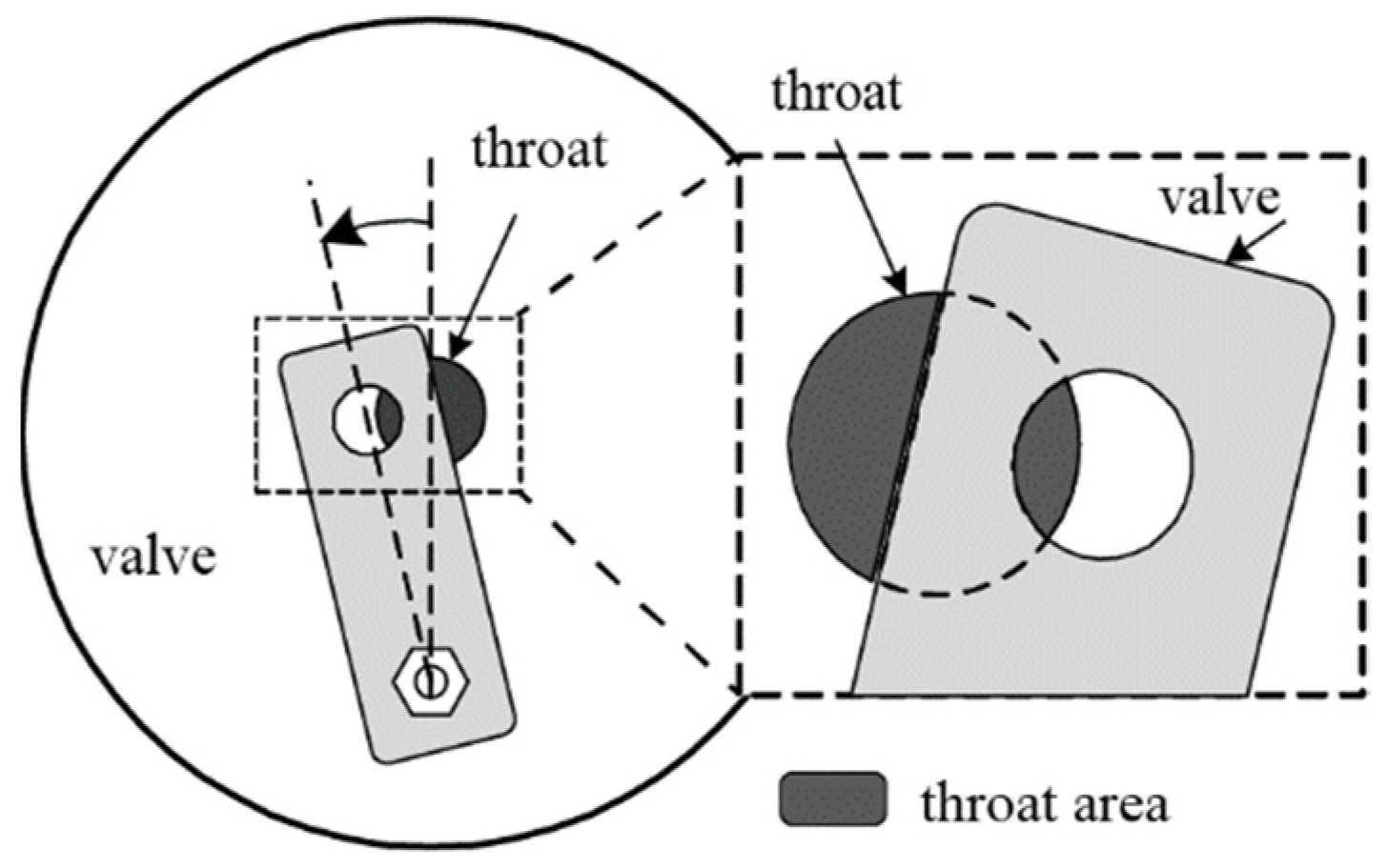
As the above mentioned, the gas generator pressure is controlled by regulating the area of the throat with a valve. Figure 2 displays a schematic diagram of the valve structure in the gas flow regulation system [12].

2.3. Control Characteristics Analysis

2.3.1. Analysis of Overshoot and Rise Time Characteristics

The PI feedback controller has strong robustness, and it can make a system perform well if designed appropriately. Therefore, a PI controller is selected as the basic controller for gas generator pressure in this study. According to Equation (2), the closed-loop transfer function from the reference instruction to the output can be expressed as
Δ P g Δ P g c = K 1 ( K P s + K I ) s 2 + ( T 1 K P K 1 ) s K I K 1
where P g c is pressure instruction, K P and K I are the control gains of the PI controller.
Introducing the damping ratio ζ and natural frequency w n to Equation (4), it can be rewritten as
Δ P g Δ P g c = w n 2 ( τ s + 1 ) s 2 + 2 ζ w n s + w n 2
where w n 2 = K I K 1 , ζ = T 1 K P K 1 2 w n .
By applying the inverse Laplace transform to Equation (5), we can determine the time domain response of the controlled system as follow:
C ( t ) = 1 e ζ w n t 1 ζ 2 l z sin ( 1 ζ 2 w n t + β + φ )
where l = z 2 2 ζ w n z + w n 2 .
According to Equation (6), the system response index can be calculated as follows:
{ σ = l z e ζ 1 ζ 2 ( π φ ) t r = π ( β + φ ) 1 ζ 2 w n
where σ is overshoot of system, t r is the rise time, l = z 2 2 ζ w n z + w n 2 .
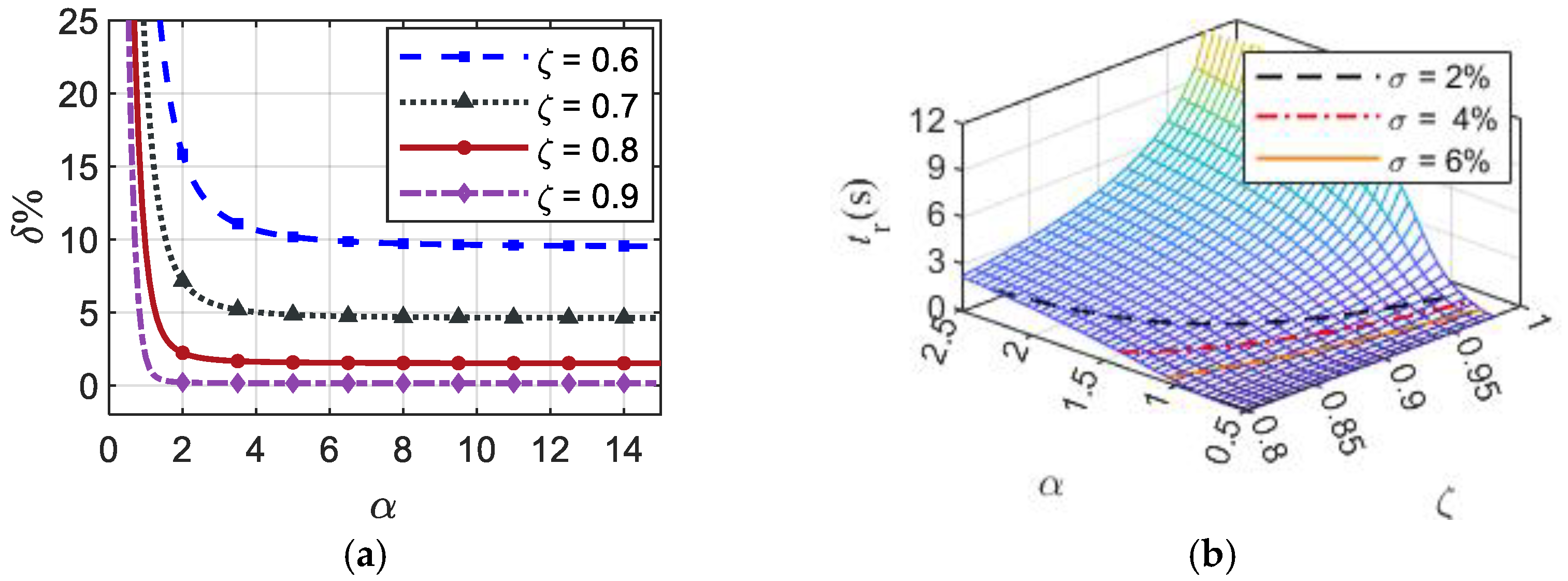
In this study, an intermediate variable α = z / ζ w n (the ratio of the zero real part to the pole real part) is selected to analyze the relationship between ζ and σ . Then, the overshoot σ and rise time t r can be formulated as
{ σ = 1 2 α + 1 ζ 2 α 2 e ζ 1 ζ 2 ( π arctan ( 1 ζ 2 ζ · α ζ ) ) t r = π ( arc tan 1 ζ 2 ζ + arctan ( 1 ζ 2 ζ · α ζ ) ) 1 ζ 2 w n
According to Equation (6), the relationship between ζ , σ and α is plotted as shown in Figure 3a. An operating point (Pg0 = 1.50 MPa, V0 = 0.025 m3) is selected to explain the relationship between α , t r , σ , and ζ (see Figure 3b). As illustrated in Figure 3, the overshoot decreases as ζ and α are increased; in addition, the rise time increases as α increases and decreases as ζ increases when the overshoot is fixed.
In Section 3.2, we will refer to the relationship between control performance with ζ and α , combining optimization methods to find ζ and α that satisfy control performance at different operating points, then complete the design of ANFIS.

2.3.2. Analysis of Anti-Regulation

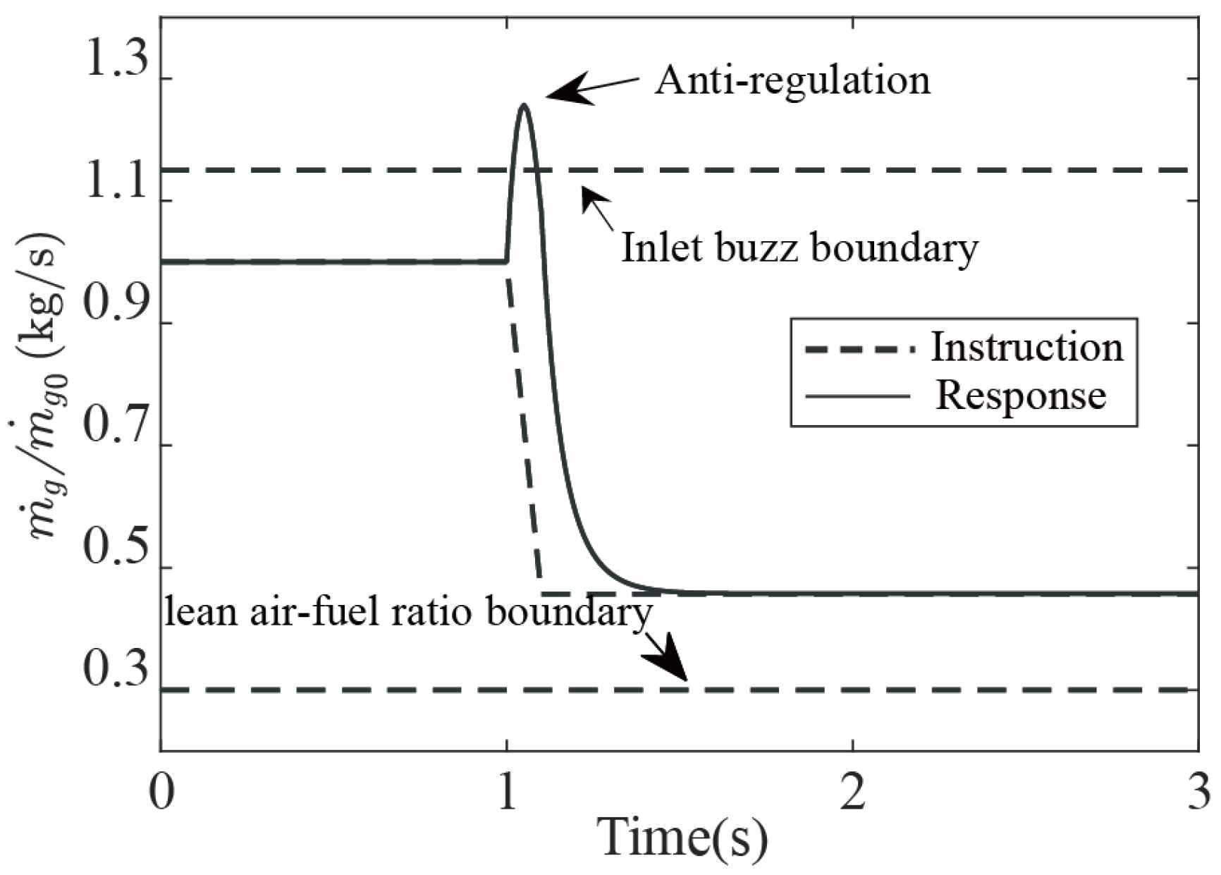
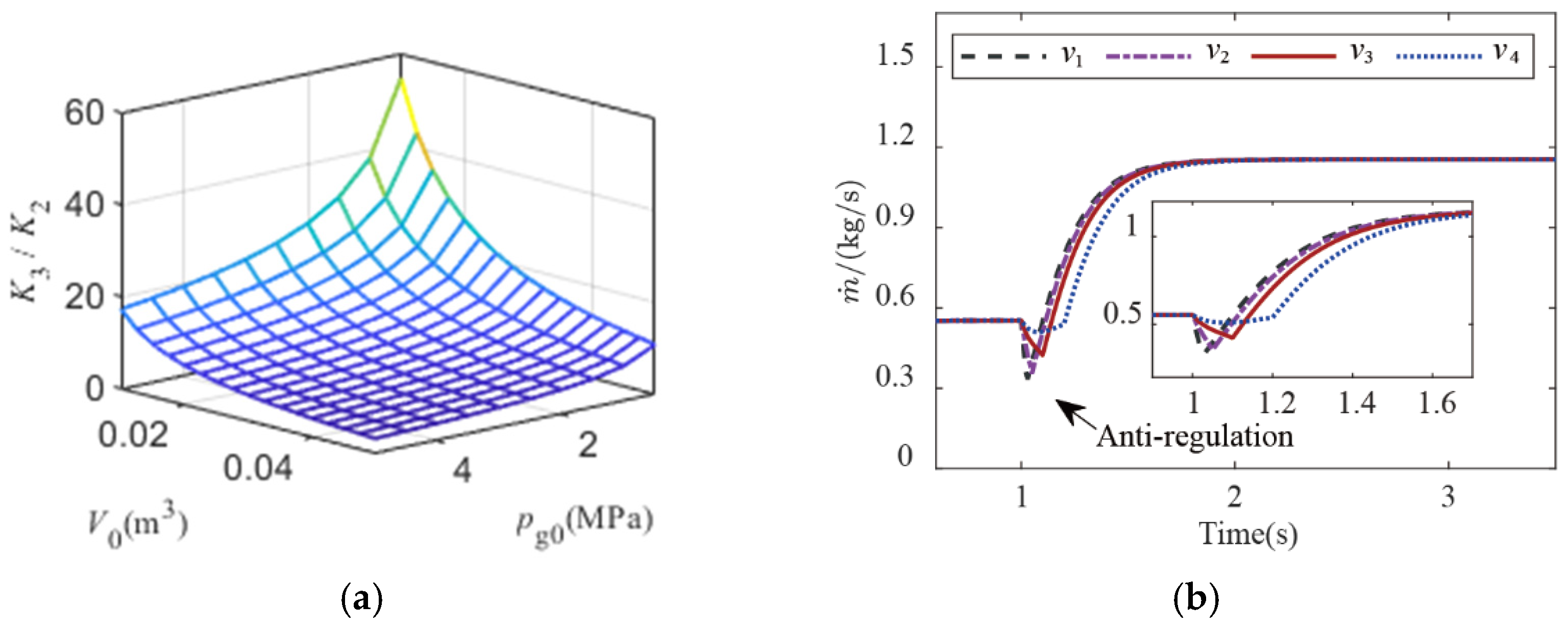
Anti-regulation causes the direction of the change in a state parameter to be the opposite of that expected. Figure 4 shows the slope response of the gas flow for a VFDR. When the valve moves at 1 s to increase the throat area, the gas flow accelerates first before equilibrating to the demand; this is the anti-regulation phenomenon. The anti-regulation of the gas flow can lead to the anti-regulation of the combustor pressure and engine thrust, unstable flight conditions, and even severe problems such as non-starting of the inlet [22]. Therefore, it is essential to consider anti-regulation when designing the controller of gas flow. According to Equation (2), the transfer function of the gas flow regulation system is a typical non-minimum phase system with a positive zero (value of K3/K2), and the value of K3/K2 is related to the system pressure and free volume. Figure 5a illustrates the relationship between P g 0 , V 0 , and K3/K2; it can be observed that the larger the pressure and free volume, the more pronounced the anti-regulation characteristics.
Besides this, the anti-regulation of the gas flow is also related to the rate of change of the throat area (which is dependent on valve move speed). Figure 5b displays the gas flow response with different throat area change rates (v1 = 0.02 m2/s, v2 = 0.01 m2/s, v3 = 0.005 m2/s, v4 = 0.0025 m2/s). The simulation result showed that the faster the rate of change in the throat area, the greater the amount of anti-regulation.
In this study, the strength of anti-regulation is described using absolute and relative anti-regulation [20]. The absolute anti-regulation was defined as the maximum amount of change in the gas flow that exhibited an inverse response opposite to the desired control signal. The relative anti-regulation was calculated by dividing the absolute change by the difference between the initial flow and steady-state flow.

3. Hybrid Adaptive Control Strategy

3.1. Control Performance Requirements and Proposed Control Framework

The control performance requirements of the gas flow are given as follows: (1) under the small free volume condition (V < 0.025 m3), the steady-state error of the gas flow response is less than 1%, the relative anti-regulation and overshoot of the gas flow are no more than 5%, the response time is no more than 2 s, the settling time is less than 3 s, and the mean relative error is less than 5%; (2) under the large free volume condition (V ≥ 0.025 m3), the steady-state error of the gas flow response is less than 1.5%, the anti-regulation and overshoot of the gas flow is no more than 10%, the response time is less than 3.5 s, the settling time is less than 4s, and the mean relative error is less than 5%; (3) the controlled system is required to accurately and stably track the pressure command within the range of 1.5 Mpa–4.5 Mpa.
The proposed second-order fuzzy adaptive tracking differentiator—ANFIS-PI controller (SOA-ANFIS-PI)—scheme is illustrated in Figure 6. The ANFIS-PI controller is a nonlinear variable control gain PI controller. The inputs of ANFIS are Pg (Mpa) and V (m3), and the output of ANFIS is the control gain of the adaptive PI controller. The inputs of SOA-TD are control instruction and V (m3), and the outputs are arranged instruction.

3.2. ANFIS-PI Controller

3.2.1. Adaptive Neuro-Fuzzy Inference System

ANFIS is an artificial intelligence technique that mimics human thinking to address uncertainty problems. As a data learning technique, it uses a fuzzy logic function to convert highly interconnected neural network processing functions into a desired output obtained from input feature information [23,24]. In ANFIS, affiliation function is obtained by training with sample data. In this study, Takagi–Sugeno fuzzy system model is used and the rules are described as [25]
r u l e 1 : i f x = A 1 , y = B 1 t h e n f 1 = m 1 x + p 1 y + r 1 r u l e 2 : i f x = A 2 , y = B 2 t h e n f 2 = m 2 x + p 2 y + r 2
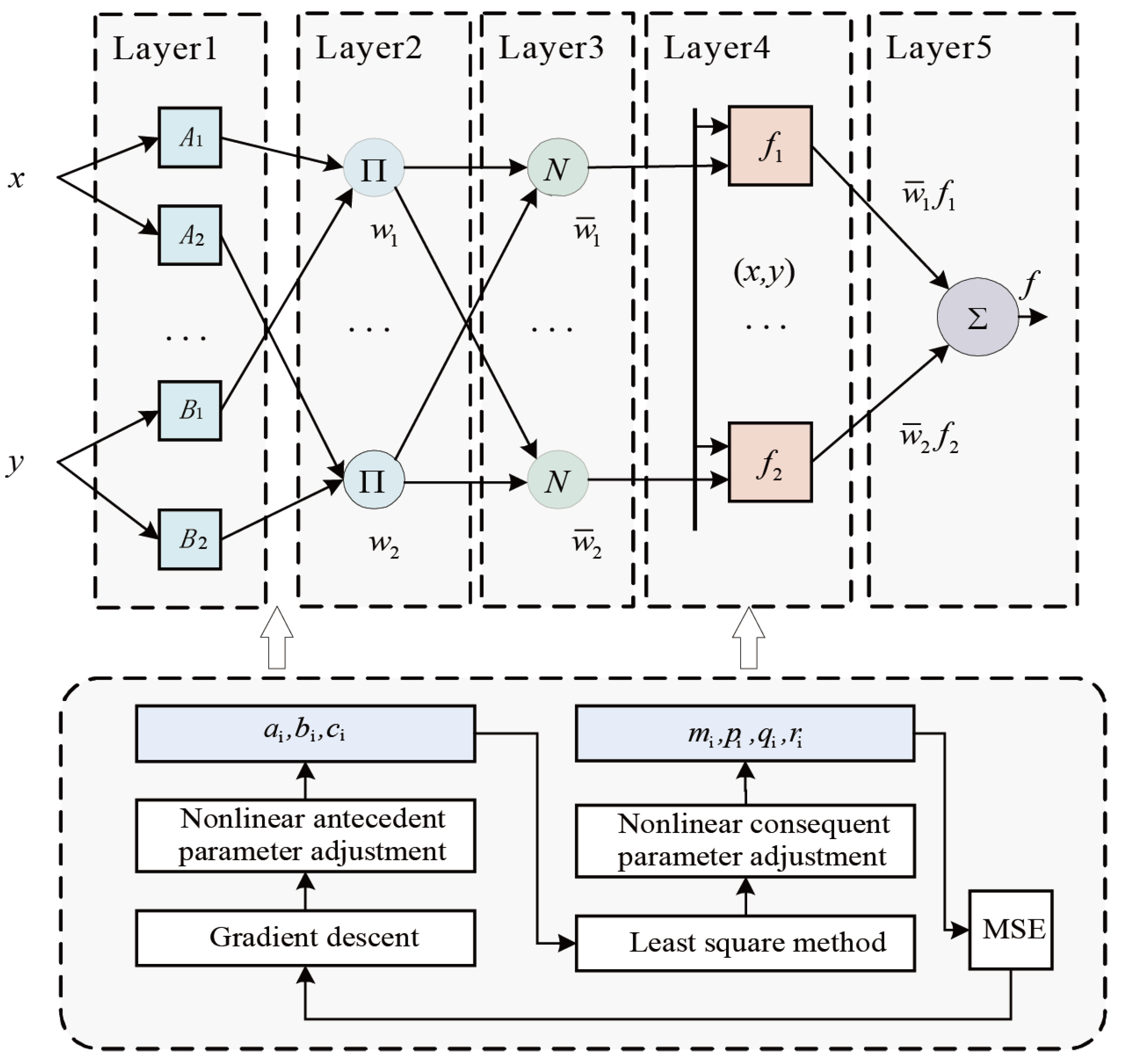
where Ai, Bi are fuzzy sets, mi, pi and ri are resulting parameters, and the fuzzy ANFIS controller consists of five layers. As shown in Figure 7, ANFIS first builds the initial fuzzy model by using the collected sample data, afterward, the model parameters are optimized by Layers 1 to 5. (The node parameters in Layer 1 and Layer 4 can be adaptively adjusted through optimization, the node parameters in Layer 2 and Layer 3 are fixed, and Layer 5 is the output of ANFIS for the model).
The structure and parameter training process for each layer of ANFIS are as follows [26]: Layer 1 is known as the input fuzzification layer.
{ O 1 , i = μ A i ( x ) O 1 , i = μ B i ( x ) O 1 , i = μ C i ( x ) i = 1 , 2 , 3 , , n
where O 1 , i is the output value of the layer, μ A i , μ B i , and μ C i are parameters of the generalized gaussian-type membership function, where
μ A i ( x ) = 1 1 + [ ( ( x c i ) a i 1 ) 2 ] b i , μ B i ( x ) = 1 1 + [ ( ( x c i ) a i 1 ) 2 ] b i
Layer 2 is known as the fuzzy and operation layer which can be expressed as
O 2 , i = w i = μ A i ( x ) μ A i ( y )
where, this layer implements fuzzy inference, and the output of each node indicates the confidence level of a particular rule.
Layer 3 is known as the normalization of each rule firing strength layer which can be expressed as
O 3 , i = w ¯ i = w i w 1 + w 2 + + w n μ A i ( x ) μ A i ( y )
Layer 4 is known as a linear rule consequence parameter layer which can be expressed as
O 4 , i = w ¯ i f i = w ¯ i ( m i x + p i y + r i ) , i = 1 , 2 , , n
Layer 5 is known as the output layer which can be expressed as
O 5 , i = w ¯ i f i = w i f w i
During each training iteration, the root-mean-square error between the actual output and the desired output decreases, and training stops when the predetermined number of training sessions has been reached.

3.2.2. System Sample Data and Training Results

As a result of the theory in Section 2.3, the process of constructing ANFIS will be elaborated in this section. Firstly, the steps to obtain the training input and output data for ANFIS are as follows:
Step 1: divide the model into different operation points based on the system pressure Pg0 and free volume V0, and obtain the transfer function of each operation point according to Equation (5).
Step 2: select a characteristic point and solve the damping ratio ζ and natural frequencies w n of the closed-loop system (see Equation (5)) by solving the optimization problem shown in Equation (16), and then solve the KP, KI at this operation point by Equation (4).
minimize J = w 1 t r + w 2 e p g = w 1 π ( arc tan 1 ζ 2 ζ + arctan ( 1 ζ 2 ζ · α ζ ) ) 1 ζ 2 w n + w 2 | p g ( ) p g c ( ) | subject   to w n > 0 1 > ζ > 0.8 l z e ζ 1 ζ 2 ( π φ ) < 0.5 % z = w n 2 2 ζ w n T 1 > 0
where w i ( i ) is the weight of the cost function (In this study, the values of w 1 and w 2 are set to 1 and 1e-3, respectively), t r is the rising time, e p g = p g ( ) p g c ( ) is the steady-state error, p g ( ) is the steady-state pressure response of the system, and p g c ( ) is the system steady-state pressure instruction.
Step 3: introduce the calculated control gains KP and KI into the control system, correct the control gains based on the prior knowledge obtained from the experimental data, and verify whether the control requirements are met via simulation. If yes, go to step 4, if not, return to step 2.
Step 4: determine whether all the operation points have been calculated, if yes, go to step 4, if not, return to step 2.
Step 5: collect the input-output data pairs (and we fine-tune the parameters KP and KI to attain a better control performance).
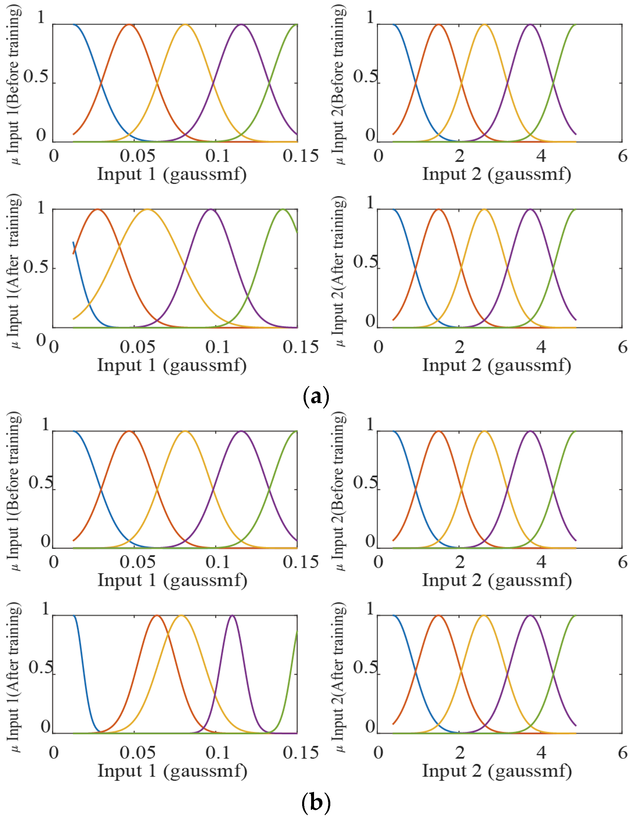
After obtaining input and output data, we trained ANFIS using the fuzzy logic toolbox of Matlab 2021b running on a 64-bit Windows 10 operating system and selected the gaussian-type affiliation function as an input affiliation function. Figure 8 shows the affiliation functions before and after training.

3.3. Second-Order Fuzzy Adaptive Tracking Differentiator

3.3.1. The Traditional Tracking Differentiator

It is clear from the analysis in Section 2.3.2 that anti-regulation is inevitable for gas flow regulation systems and the amount of anti-regulation is related to the motion rate of the valve. Therefore, the gas flow control system has a natural contradiction in the amount of anti-regulation and the response time. The literature [27] pointed out that arranging the transition process could be an effective way to solve the trade-off between overshoot and rapidity and it also showed a better application in weakening the anti-regulation. In 1995, Han gave an implementation of the arranged transition process using the fastest discrete TD, which has the advantage that the input signal can reach the target value quickly and is overshoot-free [28], and the differential signal could be extracted simultaneously. The form of the fastest discrete TD is as
{ f h = fhan ( v 1 v 0 , v 2 , r , h 0 ) v 1 = v 1 + h v 2 v 2 = v 2 + h f h { d = r 0 h 0 , d 0 = h 0 d , g = x 1 + h 0 x 2 a 0 = d 2 + 8 r 0 | g | a = { x 2 + ( a 0 d ) s i g n ( g ) / 2 , | g | > d 0 x 2 + g / h 0 , | g | d 0 fhan = r 0 { s i g n ( a ) , | a | > d a / d , | a | d
where v 0 is the reference input, v 1 is the arranged output, h 0 is the filtering factor (the smaller the h 0 , the stronger the filtering effect), and r is the velocity factor (the smaller the value for r, the stronger the “softening” effect on the instruction).
Figure 9 presents that the fastest discrete TD has no overshoot in tracking the step signal, and the transition time is determined by r, which will be infinitely close to the input signal when r is too large. Combined with the extracted differential signal curve, the transition curve has zero slopes at the beginning, which can make the tracking signal smoother. According to the previous analysis, the introduction of the fastest discrete TD will reduce the initial throat area variation rate, which can weaken the anti-regulation.

3.3.2. Design of Adaptive Tracking Differentiator

Although the TD shows good performance in uncertain model control, it cannot adaptively adjust the tracking rate due to its fixed parameters, either in the slow-varying or fast-varying intervals, which makes it difficult for TD to overcome the trade-off between response rate and anti-regulation. To overcome this drawback of traditional TD, a novel SOA-TD is proposed in this paper, whose structure is shown in Figure 10.
The improved SOA-TD consists of two adaptive TDs connected in parallel. The inputs of TD1 are the command signal and the velocity factor, which is related to the free volume, and its output is the derivative of the command signal after the arrangement transition process.
The inputs of TD2 are the command signal and the velocity factor r2, the r2 can be calculated from the output of TD1 by using the empirical formula (see Equation (18)). Then, the final command signal can be obtained by arranging the transition process of the original signal using TD2.
r 2 = a 0 r 1 ( 1 1 + e a 1 ( u b 0 ) + b 1 ) + b 2 , u = d | V 2 | d t .
where a 0 , a 1 , b 0 , b 1 , b 2 are the adaptive speed adjustment factors. To illustrate the advantages and principles of the proposed SOA-TD, a typical square wave command signal was taken as an example for explanation.
Figure 11a shows the original square wave signal Pgc and the command signal PgTD1 after the transition process arranged by TD1. Figure 11b shows the absolute value of the differential value of the original signal v2TD1 obtained by TD1 and the differential value of |v2|. Dividing the whole square wave signal period into five parts (t1t5), it is known from simulation experience that the t1 and t3 are main periods when anti-regulation occurs, during which the valve motion rate needs to change slowly to weaken the anti-regulation. Additionally, in the t2 and t4 periods, the anti-regulation generally ended, at which time the valve motion rate constraint should be released to improve the system response rate. Because the conventional TD velocity factor is constant, it cannot be adaptively adjusted. In contrast, the SOA-TD proposed in this paper can further adjust the velocity factor of TD2 according to the acceleration signal u (see Equation (18)), thus realizing the function of adaptively weakening the anti-regulation. Figure 11c shows the original pressure command signal as well as the signal after processing by TD and SOA-TD.
In addition, it should be noted that the gas flow control system is the internal loop control of the flight control system, and the gas flow control commands are calculated by the flight control system. The control command signal may contain high-frequency noise due to sensor noise and external disturbance, and the SOA-TD proposed in this paper has the function of filtering the noise signal. Figure 11d shows the filtering effect of the adaptive TD with different filtering factors on the noise of different amplitude and frequency.
Remark: 
the velocity factor r1of TD1 plays a pivotal role in determining the moment and duration of anti-regulation, while the velocity factor r2 of TD2 determines whether to relax the velocity factor constraint or not. In this paper, empirical formulas and fuzzy rules based on expert experience are used to determine r1 and r2, respectively.

4. Experimental System and Verification

4.1. HIL System of Ducted Rocket

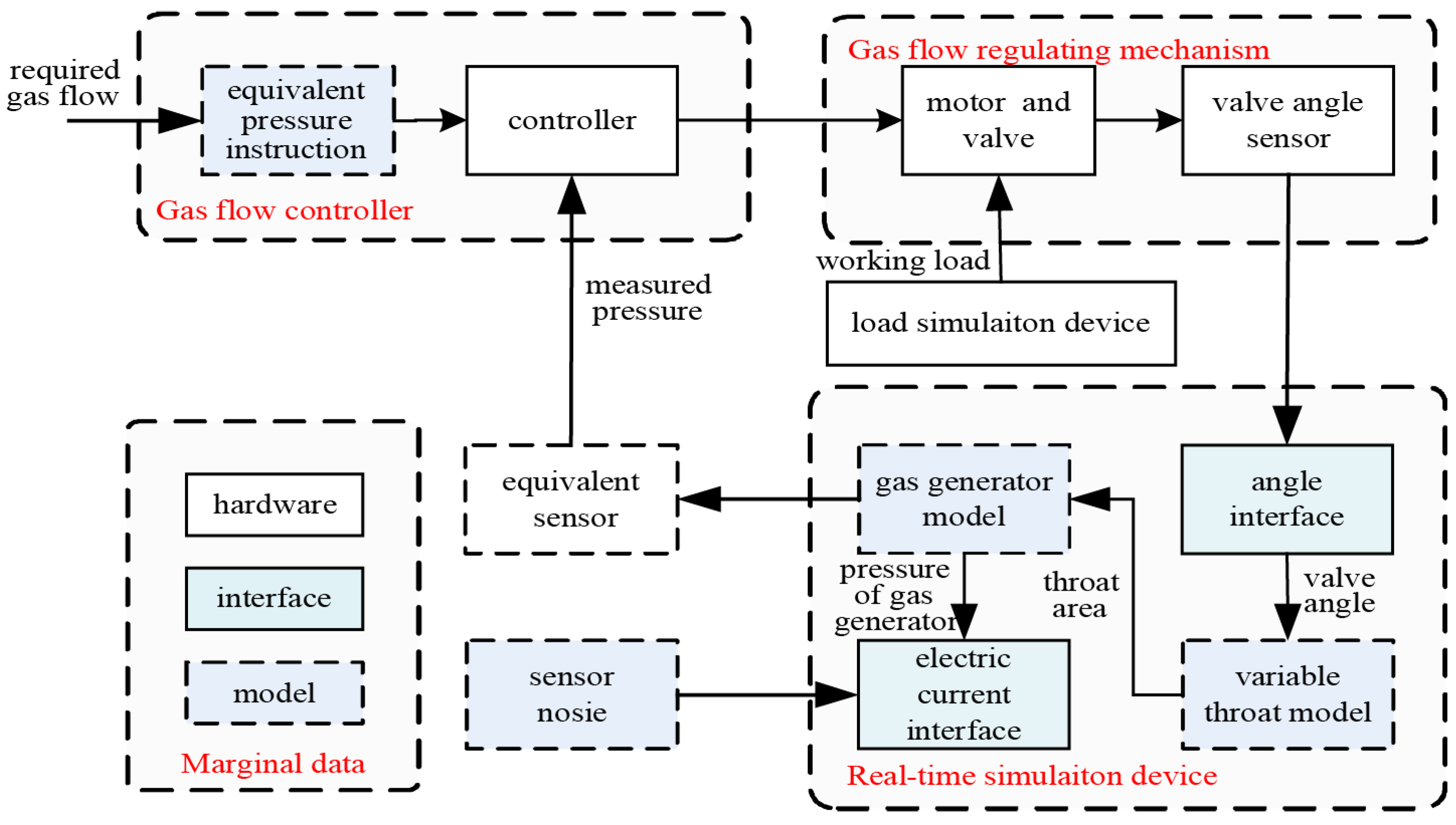
Direct-connected ground tests are needed to verify the reliability and effectiveness of the proposed algorithm. However, multiple and repeated ground tests were impossible to carry out because of huge manpower and material resource demand. Therefore, a ducted rocket experimental platform was built using hardware in loop (HIL) simulation. The components of the HIL simulation system are displayed in Figure 12, which provided various of simulation conditions by flexible configuration, and few resources were needed.
The ducted rocket HIL system is primarily composed of the following hardware (see Figure 13): controller, gas flow regulator motor, load simulation device, valve angle sensor, and real-time simulation device. The entire model in the HIL simulation is running in the real-time simulation device, including the revised gas generator model and throat model et al.
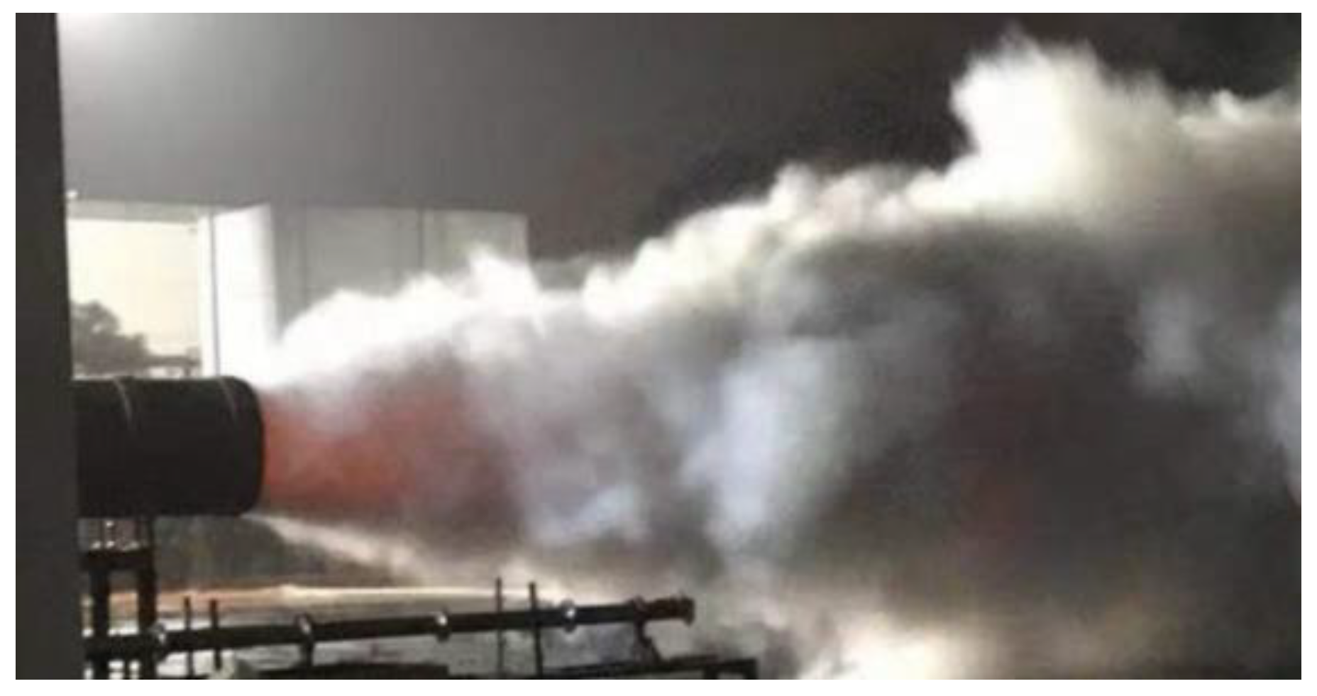
Table 1 compares the HIL simulation with the ground test of a real ducted rocket to illustrate the reliability of the simulation system. There was no difference between the motor and controller states in the two test methods above. An electric-equivalent sensor was used in the HIL simulation to substitute the real sensor, by converting the simulated pressure value into an equivalent current according to the standard and feeding it into the controller’s AD acquisition interface. In addition, a 0.1% FS noise signal is added to the sensor model as well. A working load simulation device restored the real working environment that the motor had in a real ducted rocket. A direct-connected ground test using the same experiment configuration was proposed to verify the effectiveness of HIL simulation (see Figure 14). The comparison results between the direct-connected ground test and the HIL simulation can be referred to our previous work [12].

4.2. Verification

In this section, the adaptiveness, robustness, and the ability of suppression of anti-regulation of the proposed controller were verified by using HIL simulation experiments, and the anti-windup PID controller (AW-PID), ANFIS-PI controller, and TD-ANFIS-PI controller were chosen as the compared controller to verify the advantages of the proposed controller.

4.2.1. Adaptability Verification

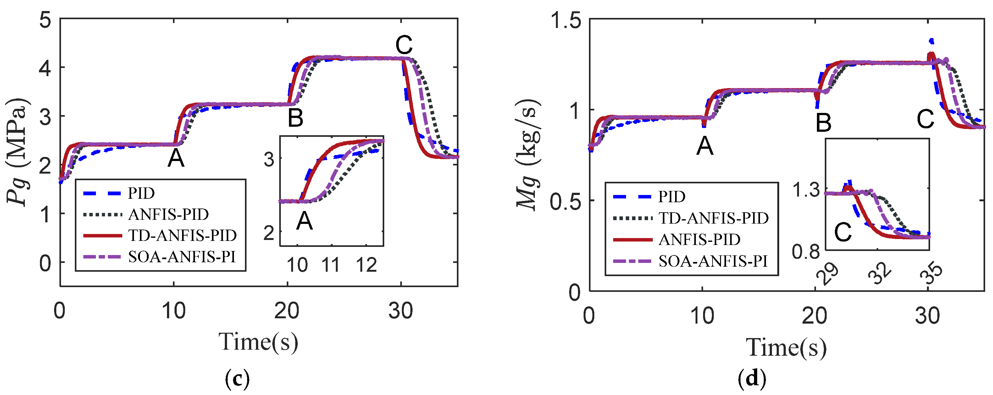
In this section, we verified the adaptability of the proposed controller. The gas flow and the pressure response were simulated and analyzed. The given HIL simulation operation conditions were shown in Table 2. Three cases (case A, case B, and case C) were selected to compare the control performance of various controllers. Control instruction and control input were shown in Figure 15a,b. Simulation results of the gas flow and the pressure response were shown in Figure 15c,d and the statistics of control performance (such as, rise time, settling time, recovery time, steady-state error, overshoot, and undershoot) of each controller at different operation points were listed in Table 3.
According to Figure 15c,d, it is easy to see that: the AW-PID controller was significantly less adaptive than the ANFIS controller, which was difficult to track effectively for changing pressure commands. The ANFIS controller, on the contrary, tracked the changing pressure command well because it adjusted the control gain adaptively according to the fuzzy neural network.
Further, compared with the ANFIS-PI controller, the TD-ANFIS-PI controller significantly suppressed the overshoot and the anti-regulation of the gas flow, but the rise time was significantly slower, while the SOA-ANFIS-PI overcame these shortcomings. It adjusted the command signal adaptively by using the SOA-TD to address the trade-off between the response rate, overshoot, and the amount of anti-regulation, and showed a better control effect.

4.2.2. Robustness Verification

The robustness of the proposed controller to external perturbations and model parameter perturbation was verified by HIL simulations as well. In the simulation, the pressure reference command is shown in Figure 16a. A perturbation signal (see Figure 16a) are applied to the HIL simulation. The pressure response with external perturbations obtained by HIL simulation is shown in Figure 16b. From the simulation results, it can be seen that the designed controller can suppress external disturbances effectively.
In addition, to verify the robustness of the proposed controller to model uncertainties, a series of model parameter perturbation are also added to the HIL simulation (see Table 4. Figure 16c,d show the pressure response and control inputs obtained by HIL simulation, respectively, and the simulation results showed that the proposed controller is robust to deviations in model parameters.

4.2.3. Anti-Regulation Suppression Verification

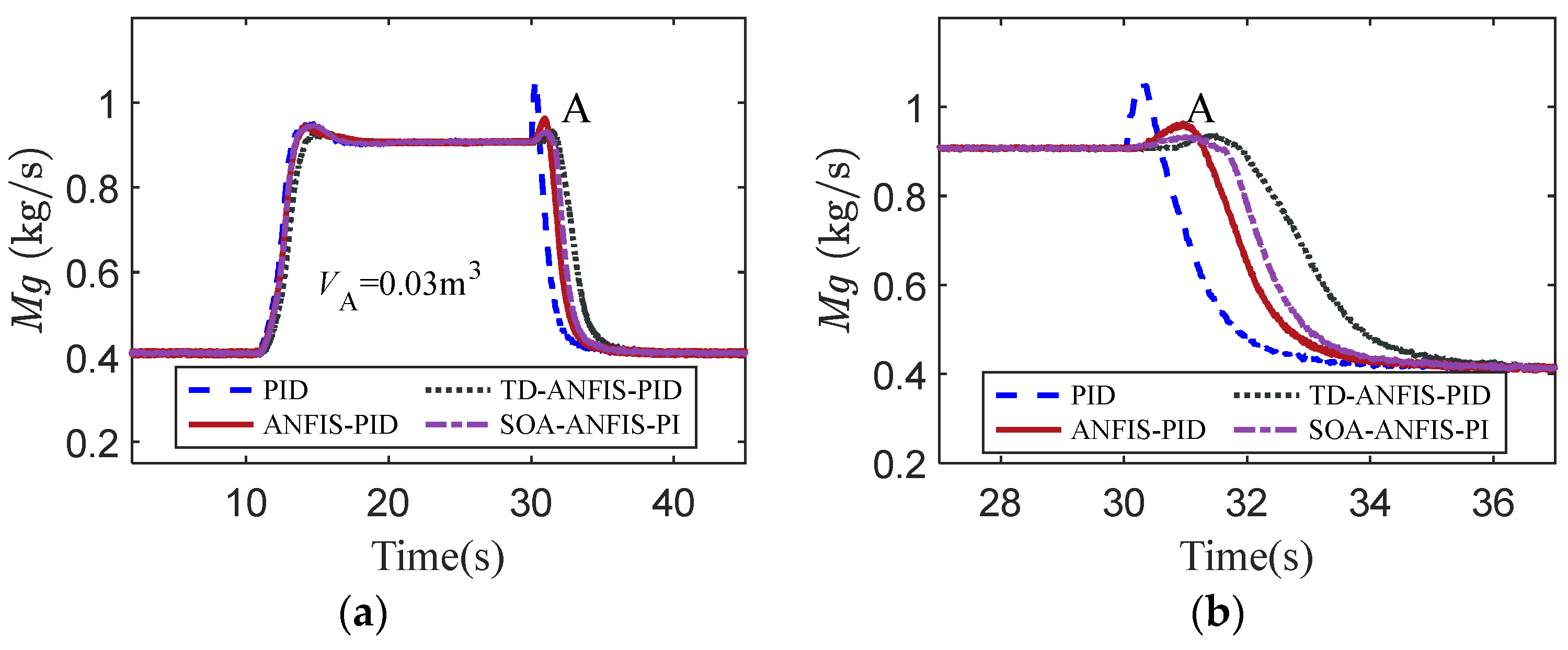
To compare the anti-regulation suppression ability of the different controllers, an additional HIL simulation was designed; more demanding simulation conditions were set as follow: the initial free volume was set to 0.03 m3, the regulation range of gas flow was 0.4 kg/s–0.9 kg/s. The response curves obtained for different control algorithms are shown in Figure 17.
From the simulation results in Figure 17, it can be seen that the proposed controller suppressed the anti-regulation significantly. Taking the simulation results in Figure 17b, for example, (the simulation time is 30–36 s) to illustrate the advantages of the proposed controller, when the anti-regulation appears, the SOA-TD actively reduces the r2 to suppress the anti-regulation, and then actively increases the velocity factor r2 to accelerate the response rate of the system after the anti-regulation ends. The simulation results showed that the designed SOA-TD algorithm had better adaptability and significantly improved the control performance by coordinating the adjustment time and the anti-regulation.

4.3. Discussion

Overall performance attributes are provided in Table 5 for comparing the performance of different controllers. All the considered controllers were able to track the pressure and gas flow instructions. Performance in response time and control adaptability was not satisfactory for AW-PID. The ANFIS-PI controller is better than the AW-PID controller in adaptability but can’t provide complete damping and therefore suffers from large overshoot and anti-regulation in terms of the pressure response and the gas flow response, respectively. The TD-ANFIS-PI controller and the SOA-ANFIS-PI controller had good performance in suppressing overshoot and anti-regulation, and the SOA-ANFIS-PI controller had a significant advantage over the TD-ANFIS-PI controller in response time.
From the summary of the results, it can be concluded that all controllers were robust and able to eliminate steady-state errors. Considering the control capability, it is easy to single out the proposed SOA-ANFIS-PI controller is the most versatile controller. The other proposed controller, TD-ANFIS-PI controller, is the next best controller. Considering the two controllers individually, the SOA-ANFIS-PI controller outperforms the TD-ANFIS-PI controller in handling the trade-off of the response time and the anti-regulation.

5. Conclusions

A composite control strategy based on a SOA-TD combined with an ANFIS-PI controller was presented for gas flow control of VFDRs with variable parameters, strong nonlinear, non-minimum phase, and multi-constrained boundary characteristics.
First, the mathematical model of the gas generator of a VFDR was established, and the closed-loop transfer functions from the reference instruction to the output at different operation points were calculated. The relationships between the control system parameters and the control performance, such as overshoot and rise time, were derived. An ANFIS PI controller satisfying the requirements of variable parameter characteristics and control constraints was designed by combining mathematical simulation and HIL simulation data.
In addition, the anti-regulation of the gas flow was analyzed. The higher the pressure of the controlled system, the larger the free volume, the faster the adjustment rate of the actuator, and the larger the anti-regulation of the gas flow. As the free volume increases with the rise in pressure of the controlled system, the rate of adjustment of the actuator is accelerated and the anti-regulation of the gas flow is larger. And there is a trade-off between the response rate and the amount of anti-regulation of the controlled object. To solve the above problems, a SOA-TD controller was designed.
Finally, a HIL simulation experiment platform of the gas flow regulation system was constructed, and serial HIL simulations were carried out to verify the validation of the proposed controller. The HIL simulation experiments showed that the proposed controller has great adaptability and robustness, and it is expected to fulfill VFDRs’ thrust control requirements across a wide range of altitudes and Mach numbers in future engineering applications.

Author Contributions

Conceptualization, Z.Z.; Data curation, Q.Z., Y.Z. and H.W.; Formal analysis, Z.Z.; Funding acquisition, Z.Z. and Q.Z.; Investigation, Z.Z.; Resources, Z.Z. and M.T.; Software, Z.Z., Y.Z. and H.W.; Supervision, Y.Z.; Visualization, Q.Z.; Writing—original draft, Z.Z.; Writing—review & editing, Q.Z., Y.Z. and M.T. All authors have read and agreed to the published version of the manuscript.

Funding

National Natural Science Foundation of China (Grant Number: 61174120).

Institutional Review Board Statement

Not applicable.

Informed Consent Statement

Not applicable.

Data Availability Statement

Not applicable.

Conflicts of Interest

The authors declare no conflict of interest.

References

  1. Waltrup, P.; White, M.; Zarlingo, F.; Gravlin, E. History of US Navy ramjet, scramjet, and mixed-cycle propulsion development. J. Propuls. Power 2002, 18, 14–27. [Google Scholar] [CrossRef]
  2. Hewitt, P. Status of ramjet programs in the United States. In Proceedings of the 44th AIAA/ASME/SAE/ASEE Joint Propulsion Conference & Exhibit, Hartford, CT, USA, 21–23 July 2008; p. 5265. [Google Scholar]
  3. Davenas, A. History of the development of solid rocket propellant in France. J. Propuls. Power 1995, 11, 285–291. [Google Scholar] [CrossRef]
  4. Wilson, R.; Limage, C.; Hewitt, P. The evolution of ramjet missile propulsion in the US and where we are headed. In Proceedings of the 32nd Joint Propulsion Conference and Exhibit, Lake Buena Vista, FL, USA, 1–3 July 1996; p. 3148. [Google Scholar]
  5. Fry, R.S. A century of ramjet propulsion technology evolution. J. Propuls. Power 2004, 20, 27–58. [Google Scholar] [CrossRef]
  6. Bauer, C.; Davenne, F.; Hopfe, N.; Kurth, G. Modelling of a throttleable ducted rocket propulsion system. In Proceedings of the 47th AIAA/ASME/SAE/ASEE Joint Propulsion Conference & Exhibit, San Diego, CA, USA, 31 July–3 August 2011; p. 5610. [Google Scholar]
  7. Pinto, P.; Kurth, G. Robust propulsion control in all flight stages of a throtteable ducted rocket. In Proceedings of the 47th AIAA/ASME/SAE/ASEE Joint Propulsion Conference & Exhibit, San Diego, CA, USA, 31 July–3 August 2011; p. 5611. [Google Scholar]
  8. Alan, A.; Yildiz, Y.; Poyraz, U. Adaptive pressure control experiment: Controller design and implementation. In Proceedings of the 2017 IEEE Conference on Control Technology and Applications (CCTA), Maui, HI, USA, 27–30 August 2017; pp. 80–85. [Google Scholar]
  9. Alan, A.; Yildiz, Y.; Poyraz, U. High-Performance Adaptive Pressure Control in the Presence of Time Delays Pressure Control for Use in Variable-Thrust Rocket Development. IEEE Control Syst. Mag. 2018, 38, 26–52. [Google Scholar] [CrossRef] [Green Version]
  10. Zhou, J.; Chen, X.; Chai, J.; Zhou, C. Researching on pressure adaptive control method for variable flow gas generator. Comput. Simul. 2020, 37, 113–118. [Google Scholar]
  11. Niu, W.; Bao, W.; Chang, J.; Cui, T.; Yu, D. Control system design and experiment of needle-type gas regulating system for ducted rocket. Proc. Inst. Mech. Eng. Part G J. Aerosp. Eng. 2010, 224, 563–573. [Google Scholar] [CrossRef]
  12. Wang, A.; Zeng, Q.; Ma, L.; Wang, H. Virtual Free-Volume Revised Method and Adaptive Control for Solid Ducted Rockets. J. Aerosp. Eng. 2021, 34, 04021053. [Google Scholar] [CrossRef]
  13. Chang, J.; Li, B.; Bao, W.; Niu, W.; Yu, D. Thrust control system design of ducted rockets. Acta Astronaut. 2011, 69, 86–95. [Google Scholar] [CrossRef]
  14. Shi, X.; Chang, J.; Bao, W.; Yu, D.; Li, B. Supersonic inlet buzz margin control of ducted rockets. Proc. Inst. Mech. Eng. Part G J. Aerosp. Eng. 2010, 224, 1131–1139. [Google Scholar] [CrossRef]
  15. Bao, W.; Li, B.; Chang, J.; Niu, W.; Yu, D. Switching control of thrust regulation and inlet buzz protection for ducted rocket. Acta Astronaut. 2010, 67, 764–773. [Google Scholar] [CrossRef]
  16. Qi, Y.; Bao, W.; Zhang, Q.; Cao, R. Command switching based multiobjective safety protection control for inlet buzz of scramjet engine. J. Frankl. Inst. 2015, 352, 5191–5213. [Google Scholar] [CrossRef]
  17. Wilkerson, F.; Lucas, J. Variable flow solid propellant gas generator for missile control systems. In Proceedings of the 17th Joint Propulsion Conference, Colorado Springs, CO, USA, 27–29 July 1981; p. 1464. [Google Scholar]
  18. Lau, K.; Middleton, R.H.; Braslavsky, J.H. Undershoot and settling time tradeoffs for nonminimum phase systems. IEEE Trans. Autom. Control 2003, 48, 1389–1393. [Google Scholar] [CrossRef]
  19. Qiu, L.; Davison, E.J. Performance limitations of non-minimum phase systems in the servomechanism problem. Automatica 1993, 29, 337–349. [Google Scholar] [CrossRef]
  20. Chai, J.; Chen, X.; He, K.; Zhou, J. Research on tracking differentiator for variable flow gas generator. J. Propuls. Technol. 2019, 40, 1153–1161. [Google Scholar]
  21. Zhao, Z.; Chen, X.; Zhou, C.; Li, H. Research on optimum feedforward control of gas flow regulation of solid rocket ramjet. J. Proj. Rocket. Missiles Guid. 2014, 34, 109–112. [Google Scholar]
  22. Chang, J.T.; Li, N.; Xu, K.J.; Bao, W.; Yu, D.R. Recent research progress on unstart mechanism, detection and control of hypersonic inlet. Prog. Aerosp. Sci. 2017, 89, 1–22. [Google Scholar] [CrossRef]
  23. Walia, N.; Singh, H.; Sharma, A. ANFIS: Adaptive neuro-fuzzy inference system-a survey. Int. J. Comput. Appl. 2015, 123, 32–38. [Google Scholar] [CrossRef]
  24. Güler, I.; Übeyli, E.D. Adaptive neuro-fuzzy inference system for classification of EEG signals using wavelet coefficients. J. Neurosci. Methods 2005, 148, 113–121. [Google Scholar] [CrossRef]
  25. Xie, S.; Xie, Y.; Li, F.; Jiang, Z.; Gui, W. Hybrid fuzzy control for the goethite process in zinc production plant combining type-1 and type-2 fuzzy logics. Neurocomputing 2019, 366, 170–177. [Google Scholar] [CrossRef]
  26. Premkumar, K.; Manikandan, B. Fuzzy PID supervised online ANFIS based speed controller for brushless dc motor. Neurocomputing 2015, 157, 76–90. [Google Scholar] [CrossRef]
  27. Jin, H.; Song, J.; Lan, W.; Gao, Z. On the characteristics of ADRC: A PID interpretation. Sci. China Inf. Sci. 2020, 63, 209201. [Google Scholar] [CrossRef]
  28. Deng, B.; Xu, J. Trajectory Tracking Based on Active Disturbance Rejection Control for Compound Unmanned Aircraft. Aerospace 2022, 9, 313. [Google Scholar] [CrossRef]
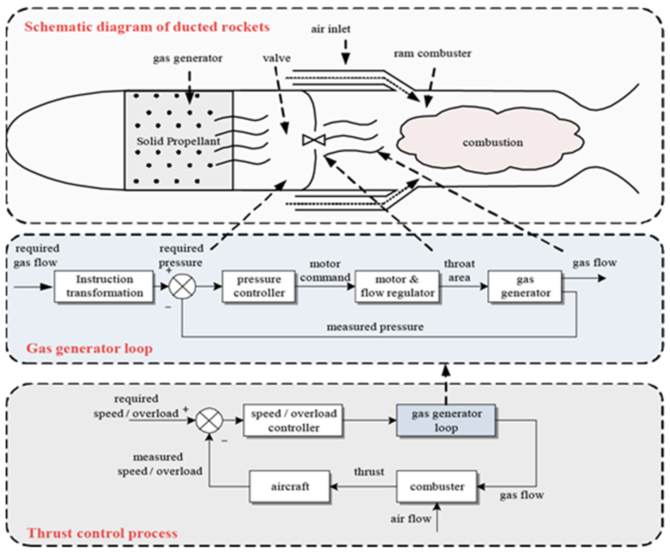
Figure 1. Schematic diagram of VFDR and gas flow control process.
Aerospace 09 00595 g001
Figure 2. Schematic diagram of the servo valve.
Aerospace 09 00595 g002
Figure 3. The relationship of α , t r , σ , and ζ (a) The relationship of α , ζ , and σ ; (b) The relationship of α , t r , σ , and ζ .
Aerospace 09 00595 g003
Figure 4. Anti-regulation of the gas flow and the security boundaries.
Aerospace 09 00595 g004
Figure 5. Anti-regulation characteristics analysis (a) Value of K3/K2; (b) Simulation of the anti-regulation of the gas flow.
Aerospace 09 00595 g005
Figure 6. Schematic diagram of proposed SOA-ANFIS-PI controller.
Aerospace 09 00595 g006
Figure 7. Schematic diagram of ANFIS.
Aerospace 09 00595 g007
Figure 8. Comparison of affiliation functions before and after training of KI and KP (a) The affiliation function of free volume before training; (b) The affiliation function of pressure after training.
Aerospace 09 00595 g008
Figure 9. Comparison of signals before and after the arrangement transition process.
Aerospace 09 00595 g009
Figure 10. Schematic diagram of the SOA-TD.
Aerospace 09 00595 g010
Figure 11. SOA-TD working principle (a) Compare Pgc with PgTD1; (b) The | V 1 T D 1 | and a T D 1 ; (c) The Pgc with PgTD1 and PgTD2; (d) Control instruction and filtering instruction.
Aerospace 09 00595 g011
Figure 12. Schematic of the HIL system.
Aerospace 09 00595 g012
Figure 13. Hardware in loop simulation system for the ducted rocket [12] ① Flow Regulator valve; ② Flow Regulator Motor; ③ Controller; ④ Load Simulation Device; ⑤ Real-Time Simulation Device; ⑥ Simulation Station; ⑦ Ground Test Device; ⑧ Sensor Cable; ⑨ System Power.
Aerospace 09 00595 g013
Figure 14. Direct-connected ground test of a ducted rocket [12].
Aerospace 09 00595 g014
Figure 15. Control results of the HIL (a) Control instruction; (b) Control input; (c) Gas flow response; (d) Pressure response.
Aerospace 09 00595 g015aAerospace 09 00595 g015b
Figure 16. Response results (a) Pressure instruction and disturbance; (b) Pressure response; (c) Control input; (d) Gas flow response.
Aerospace 09 00595 g016
Figure 17. Comparison of anti-regulation suppression ability of various controllers (a) Gas flow response; (b) Gas flow response.
Aerospace 09 00595 g017
Table 1. Comparison between the HIL simulation and direct-connected ground test.
ComponentsHIL SimulationReal Rocket Ground Test
Motorcoincident
Controllercoincident
Sensorreal hardwareequivalent sensor
Flow regulatorreal hardwaremodel + hardware
Working loadgas flow impactload simulation
Ducted rocketreal hardwarerevised model
Table 2. Simulation commands.
ParameterTime(s)Range of Gas Flow Command(kg/s)Range of Pressure Command(MPa)Free Volume(m3)Motor-Load ( N · M )
Case
Case A10–150.95–1.102.42–3.24V = 0.02140
Case B20–251.10–1.253.24–4.18V = 0.02940
Case C30–351.25–0.904.18–2.14V = 0.03640
Table 3. Control performance for different controllers.
ControllerCaseControl Performance Parameter
Rise
Time (s)
Peak Overshoot (%)Peak
Undershoot
(kg/s)
Peak
Under Shoot (%)
Settling Time (s)Steady
State
Error (%)
MRE
(%)
AW-PIDA2.390%0.04832.01%6.50<2%5.25%
B1.010%0.09563.45%4.28
C4.710%0.14093.55%9.26
ANFIS-PIA1.095.9%0.03321.67%2.27<1%2.72%
B1.360.8%0.04328.67%2.23
C2.190%0.05916.90%3.78
TD-ANFIS-PIA2.230%0.0032.00%3.51<1%5.54%
B2.560%0.0021.13%3.30
C3.970%0.0288.00%4.63
SOA-ANFIS-PIA1.724.4%0.0042.60%2.51<1%4.62%
B1.940.6%0.0042.48%2.56
C3.170%0.0339.40%3.96
Table 4. The perturbation of model parameters.
CaseAbCrR·TCaseAbCrR·T
Case 00%0%0%Case 50%−10%0%
Case 1−5%−10%−20%Case 6−5%10%0%
Case 20%0%−20%Case 7−5%0%20%
Case 35%10%−20%Case 80%−10%20%
Case 45%0%0%Case 95%−10%20%
Table 5. Comparative performance analysis of considered controllers.
ControllerControl Performance
RobustnessMRETracking AbilitySteady
Error
Response TimeSettling TimeImproved Anti-Regulation
AW-PID××××××
ANFIS-PI×
TD-ANFIS PI××
SOA-ANFIS-PI
Publisher’s Note: MDPI stays neutral with regard to jurisdictional claims in published maps and institutional affiliations.