Review

A Review of Research on the Vacuum Plume

1
School of Astronautics, Beihang University, Beijing 100191, China
2
Key Laboratory of Spacecraft Design Optimization & Dynamic Simulation Technologies, Ministry of Education, Beijing 100191, China
*
Author to whom correspondence should be addressed.
Aerospace 2022, 9(11), 706; https://doi.org/10.3390/aerospace9110706
Submission received: 28 August 2022 / Revised: 2 November 2022 / Accepted: 7 November 2022 / Published: 11 November 2022

Abstract

:
Chemical and electrical thrusters are generally utilized to control the attitude and orbit of spacecraft in aerospace. When they are firing, the exhaust expands into the vacuum environment, known as the vacuum plume. The plume flow can collide with spacecraft surfaces due to sufficient expansion, exerting adverse effects on the spacecraft, such as heating load, force/torque, contamination, and sputtering. Therefore, it is vital to investigate the vacuum plume to ensure the function and safety of the spacecraft. This review introduces the ground test and numerical simulation methods of the vacuum plume for chemical and electrical thrusters. The vacuum environment, invasive, and non-invasive (optical) measurements of the ground test are concluded. Numerical simulation of plume flow and its effects is exampled. The hybrid CFD-DSMC (computational fluid dynamics and direct simulation Monte Carlo) algorithm is employed to simulate the gas plume flow spanning continuum and transitional and free molecular flow regimes for chemical thrusters. By contrast, the PIC-DSMC (particle-in-cell plus direct simulation Monte Carlo) algorithm is used for the plasma plume flow containing charged particles exhausted by electrical thrusters. Moreover, the topics of fast prediction of the vacuum plume, plume–surface interaction, and plume–Lunar/Mars regolith interaction are proposed for future research.

1. Introduction

In aerospace, chemical thrusters, which create thrust by accelerating the resultant gas produced via chemical reactions, are frequently employed to control the attitude and maneuver the orbit of spacecraft. When the thruster fires, the exhaust expands freely to the external low-background pressure (or vacuum) environment, generating a plume-like flow field, known as the vacuum plume [1,2,3], as shown in Figure 1. The vacuum plume not only displays intriguing flow motion, but also plays a vital role in the design and usage of spacecraft. For instance, the plume can impinge on the adjacent surfaces of the spacecraft (such as the solar plane, optical lens, and thermal coating) due to sufficient expansion, leading to the unexpected heat flux [4,5,6], force/torque [5,6], contamination [5,6,7,8,9], and erosion [10,11], and eventually reducing the function and performance of the spacecraft. In particular, under the circumstance of rendezvous and docking involving two vehicles, the plume flow produced by the decreasing/increasing the thruster of the active vehicle is directed toward the passive vehicle. A significant fraction of the plume flow could collide with the surface directly, endangering the safety of the passive vehicle. Several failures induced by the vacuum plume on the actual spacecraft have been reported. Consequently, it is crucial to investigate the vacuum plume and its effects for the design and safety of spacecraft.
The spatial gradient of plume properties varies dramatically, making plume flow span continuum, transitional and free molecular flow regimes, as illustrated in Figure 1. The flow regime is classified by a dimensionless number, Knudsen number ( K n ), defined as the ratio of the molecular mean free path length ( λ ) to a representative physical length scale (l) [12,13],
K n = λ l .
The continuum regime is generally characterized by K n < 0.1 , the transition regime by 0.1 < K n < 10 , and the free molecule regime by K n > 10 . Studies on the vacuum plume can be dated back to the 1960s [14,15,16,17,18], serving the Apollo program. Researchers have devoted remarkable efforts toward the vacuum plume and its effects [19,20,21,22,23,24,25,26,27]. Dettleff [28] summarized and reviewed the research of the last century, including simplified analytical models of plume flow and plume impingement, two-plume interactions, test facilities, and experimental techniques. Simplified analytical models [29,30,31,32,33,34,35] can be utilized to evaluate the vacuum plume quickly. However, the analytical results are consistent with the numerical and experimental results at the axis region but not at the off-axis region [28]. Hence, the vacuum plume is mainly assessed numerically and experimentally now. As shown in Figure 1b, the vacuum plume flow spans different regimes, complicating the numerical simulations compared to the continuous flow commonly encountered, where the vacuum plume flow and the continuous flow are characterized by the Boltzmann equation and Navier–Stokes (NS) equation, respectively. Various algorithms [24,25,26,27,36,37] have been developed to simulate the vacuum plume numerically, and the hybrid CFD-DSMC (computational fluid dynamics and direct simulation Monte Carlo) algorithm is the most popular one [1,27].
Electrical thrusters, which generate thrust by expelling ionized gas (such as xenon and iodine), have been widely used since they offer unique advantages over chemical thrusters, such as high specific impulse, long lifespan, and high control accuracy [38,39,40,41]. In addition to the unfavorable effects described for chimerical thrusters, the plasma plume exhausted by the electrical thrusters contains high-energy charged particles, making the sputtering take place as it collides with the spacecraft surfaces [42]. By analogy, to guarantee the safety and performance of spacecraft, the plasma plume of electrical thrusters has been given much attention and evaluated experimentally and numerically [43,44,45,46,47,48,49]. Unlike the gas plume flow of chemical thruster, the rarefied flow and charged particles must be taken into account simultaneously for the plasma plume. Hence, the PIC-DSMC (particle-in-cell plus direct simulation Monte Carlo) algorithm is commonly utilized to assess the plasma plume and its effects [50,51].
In this review, we primarily introduce the ground test and numerical simulation methods for the vacuum plume of chemical and electrical thrusters. Moreover, several topics are proposed for future research. Note that the on-orbit tests have been performed for chemical thrusters [7] and electrical thrusters [52,53], with the programs of the Shuttle Plume Impingement Flight Experiment (SPIFEX) on STS-64 (Space Transportation System of the National Aeronautics and Space Administration), the Plume Impingement Contamination (PIC) Flight Experiment on STS-74, etc. Since the on-orbit measurement methods are approximately identical to the ground, they will not be presented here, and the details are available in Refs. [7,52,53] if one is interested.

2. Vacuum Plume of Chemical Thruster

It is difficult to directly assess the vacuum plume and its effects on a full-size spacecraft through experiments on the ground. On the one hand, various thrusters are utilized on the spacecraft. It is tough to maintain a vacuum environment when these actual thrusters with the high mass flow rate of propellant are working, which makes the measured plume properties deviate from the actual value (discussed below). On the other hand, the dimension of full-scale spacecraft requiring a large vacuum chamber is a challenge. Therefore, small single [1,54,55], paralleled [56,57], or clustered thrusters are experimentally tested on the ground to model the vacuum plume and provide validation data for numerical simulation. After that, the vacuum plume and its effect are numerically assessed for the full-scale spacecraft. In this section, we primarily introduce the ground test and numerical simulation methods for chemical thrusters.

2.1. Ground Test

To simulate the actual environment in aerospace, the ground test is carried out in a highly vacuumed chamber. The plume shape (properties) dramatically depends on the background pressure, as shown in Figure 2. Meanwhile, the vacuum chamber may interfere with the plume flow, as its size is relatively small because of the plume expansion. Therefore, the steady-state background pressure (the pressure when the thruster is firing) and dimension are the crucial parameters for the vacuum chamber.
The challenge to maintain a high vacuum environment in the ground test is to pump hydrogen ( H 2 ), being an essential component in both the mono- and bipropellant plume since the condensing temperature of H 2 is extremely low (≈5 K). The cooling agent of liquid helium with the temperature of ≈4.2 K is utilized to condense the hydrogen. Thus, the capacity of a vacuum chamber is mainly determined by its liquid helium system. The famous vacuum chambers with the liquid helium system designed for the ground test of the vacuum plume include STG (in German: Simulationsanlage für Treibstrahlen in Göttingen) of German Aerospace Center [58], Collaborative High Altitude Flow Facility-4 (CHAFF-4) of the University of Southern California [59], and Plume Effects Experimental System (PES) of Beihang University [60,61]. Figure 3 shows the vacuum chamber (with a dimension of Φ 5.2 m × 12.6 m ) of the PES. An internal cryopump with a liquid helium circulation system was developed for the PES, and its efficient absorption area is 305 m 2 , enabling the absorption capability of the cryopump to exceed 7 × 10 7 L/s. The test results show that the steady-state background pressures of the PES are 8 × 10 4 Pa and 1.1 × 10 2 Pa as a cold nitrogen thruster (2 g/s) and a bipropellant thruster (39.8 g/s) are firing, respectively. The detail of the PES is introduced in our previous study [60,61].
The ground test includes the measurement of the plume flow properties (e.g., pressure, velocity, temperature, and species component) and the corresponding plume effect (e.g., force/torque, heat flux, and contamination). Compared with other parameters, the pressure is the easiest parameter to measure, realized by a Pitot tube [56,62] or the pressure-sensitive paint technique (PSP) [63,64,65,66]. Figure 4a depicts a schematic of a Pitot tube array. The pressure is achieved by the differential pressure transducers, and the typical measured results are displayed in Figure 4b. Alternatively, the pressure and force induced by the plume plow can be detected by the PSP based on the oxygen-quenching principle [63,64,65,66]. Wu et al. [63] experimentally validated this technology in measuring the aerodynamic force of plume flow through cylindrical nozzles fed with the dry air, showing a good agreement with the DSMC results. Nevertheless, the PSP is temperature-sensitive and requires oxygen molecules, diminishing its application scenarios. The force/torque exerted on a surface can be indirectly obtained by integrating the pressure (measured by the Pitot tube) distributed on the surface [54]. Various force/momentum flux measurement devices have been invented to measure the force/torque directly; see Refs. [67,68].
In principle, a variety of measurement techniques can be applied to the velocity measurement, such as the Pitot tube [69], hot-wire anemometer [70], phase Doppler particle analyzer (PDPA) [71], tunable diode laser absorption spectroscopy (TDLAS) [72], particle image velocimetry (PIV) [73], and molecular tagging velocimetry (MTV) [74]. However, the adoption of the Pitot tube and hot-wire anemometers for plume velocity measurement is limited by their narrow measurement range (up to ∼100 m/s). TDLAS and PDPA measure the gas velocity using the Doppler shift, and their measurement range can be up to ∼1000 m/s. The Doppler shift refers to the effect that a mean flow of the gas in the path of the laser beam can be seen as a shift in the absorption spectrum. Song et al. [72] used the TDLAS based on Doppler shift to measure the plume velocity of solid propellant rocket motors at the standard atmospheric pressure, where the absorption spectrum of water vapor featured at 1391.7 nm is utilized to measure the velocity, as presented in Figure 5. Since water vapor is a basic residue of most chemical thrusters, the TDLAS has the potential to measure the plume velocity in a vacuum environment.
PIV measures the flow velocity by calculating the motion of tracer particles, which are seeded into the fluid. The tracer particles are sufficiently small ( μ m) and assumed to follow the flow dynamics faithfully. The measurement range of PIV is up to ∼1000 m/s. We employed the PIV to measure the plume flow of a conical nozzle and a bell nozzle with the propellant of cold nitrogen (N 2 ), as shown in Figure 6a,b. The total pressure and N 2 mass flow of two nozzles are 0.3 MPa and 3 g/s, respectively. The tracer particles are titanium dioxide with a characteristic diameter of 50 μ m. The deviation between the PIV results and DSMC results is about 10%. As discussed above, the tracer particles are indispensable for the PIV measurement, which is only validated by cold gas. Broadcasting these tracer particles into propellants, such as monomethylhydrazine and nitrous oxide (MMH/NTO), is a crucial issue that enables further applications of PIV to various chemical thrusters.
In addition to the difficulty in broadcasting the trace particles, the severe particle lag effects could lead to failure in the PIV measurement, even when employing small particles ( 0.1 μ m) for the supersonic gas flow [75]. The MTV overcomes the lag effects by tagging the gas molecules directly. The gas velocity is then determined by tracking the tagged molecules. Therefore, MTV is more applicable in measuring the hot exhaust of chemical thrusters. MTV can be categorized as seeded [75] and unseeded [76,77,78,79] MTVs. The unseeded MTV refers to the method of tagging the gas molecules that are the components of the thruster exhaust, while the seeded gas molecules are for the seeded MTV. Again, it is relatively challenging to seed the extra gas to the hot exhaust; hence, we focus on the unseeded MTV here. According to the species of tagging molecules, the unseeded MTV contains hydroxyl tagging velocimetry (HTV) [76,77,78], nitric oxide (NO) fluorescence tagging velocimetry (NTV) [79], imidogen (NH) tagging velocimetry [74,80], etc. Ramsey et al. [78] employed the HTV to measure the hot exhaust of a bell nozzle with the propellant of 90.8% hydrogen peroxide, as shown in Figure 7. The water vapor in the exhaust is dissociated by a “write” laser (a pulse of 193 nm ArF excimer laser) to generate hydroxyl (OH). The OH tag is recorded by laser-induced fluorescence (LIF) excited by a “read” laser pulse (at 283 nm). The highest gas velocity measured by the HTV is about 1600 m/s, as displayed in Figure 7b. Danehy et al. [79] applied the NTV to measure the velocity profile in a Mach 8.5 laminar, hypersonic boundary layer in a shock tunnel. Nitric oxide (NO), the tagging molecule, is generated naturally by the shock-heating process within a gas mixture of O 2 /N 2 . The maximum velocity measured is over 3000 m/s. Compared with other MTVs, the requirement of the HTV is water vapor, which is a primary component of the hot exhaust for most of the chemical thrusters. Consequently, it is the most promising technique to detect the plume velocity of chemical thrusters.
The plume temperature/heat flux can be measured by thermocouples [62], infrared camera, TDLAS [81,82], thermo paper [5,6], and heat flux sensors [55]. The thermocouple and infrared camera are primary devices for temperature monitoring. To our best knowledge, although the measurement of plume temperature by TDLAS has not been reported, it has been used to measure the temperature of high-temperature gases for a long time [82]. Hence, it is applicable in the plume temperature measurement. Trinks and Hoffman [5,6] obtained the heat flux through thermocouples and calibrated thermo paper. The heat flux sensors, which provide a variety of measurement ranges, are the most simple way to directly evaluate the plume heat effect. Zhang et al. [55] measured the heat flux distribution of the plume produced by a bipropellant thruster, using Gardon gages (heat flux senor) with the different measurement ranges. The measured results coincide with the DSMC results, showing that the heat flux sensor is reliable.
The exhausted plume of chemical thrusters contains the gas [83,84] and droplets [7], which are the primary source of contamination. Compared with the droplets, the gas properties can be readily obtained by the experimental methods described above. However, droplet distribution is one of the most challenging measurements. Dettleff and Grabe [3] used a collar located around the nozzle exit to visualize the droplets after the thruster fires, proving the existence of droplets. Still, it cannot obtain the droplet distribution. The authors [3] further proposed two means to detect the droplets qualitatively. One is the electrostatic pressure probe by monitoring the voltage variation as the electrically charged droplets hit the probe. The other is the laser beam attenuation by detecting the laser density when the droplets pass through the laser beam. Trinks and Hoffman [5,6] utilized the quartz crystal microbalance (QCM) to measure the plume deposition at different regions. However, the gas could also deposit on the QCM [83,84], making it hard to distinguish the droplets and the gas. The authors [5,6] also employed a photographic method to analyze the droplet size and angular distribution via capturing the droplets deposited on the glass positioned around the thruster. Meanwhile, the flow structure, droplet mass flow rate, and droplet velocity are detected by electric field sensors. The PDPA has been extensively used to measure the droplet flow mass rate, diameter, and velocity distribution in the field of spray [85,86], and its accuracy and efficiency have been demonstrated. Compared with other techniques, PDPA is a type of non-invasive measurement and offers massive value information. Therefore, it is highly recommended to measure the droplet distribution in the plume flow quantitatively in the future.
There are other parameters that can be discovered. The density of plume flow can be qualitatively visualized by the Schlieren photograph [87] and glow–discharge flow visualization [88]; the density of the backflow (rarefied) flow can be measured by the Patterson probe [3]. The plume components (concentration) can be explored by the mass spectrometer [5], TDLAS [81], and laser-induced fluorescence (LIF) [89,90,91,92]. The details are not listed here; one can understand them from the corresponding literature.

2.2. Numerical Simulation

The simulation algorithms utilized depend on the flow regimes [1,21]. The continuum regime is simulated by solving the Navier–Stokes (NS) equation using the traditional CFD solvers, whereas the rarefied regime is simulated by the DSMC solver. In DSMC implementation, the flow domain is divided into numerous cells, and then the simulated particles with the information of position, velocity, internal energy, and weight factor are placed into cells. During each time step, the treatment of all particles is performed by two loops. The outer loop extends over all grid cells, where all particles move and interact with the boundary surfaces. The inner loop extends over the particles within a cell where particles collide with each other. For gas molecule collisions, a possible collision pair is randomly selected and sampled based on the collision probability. Several schemes, such as randomly sampled frequency, time counter, no-time-counter method, null-collision method, collision frequency method, and main frequency method, can be used for collision sampling. The collision models of gas molecules consist of HS (hard sphere), VHS (variable hard sphere), and VSS (variable soft sphere) models. The gas molecules’ solid surfaces can be modeled by specular reflection, diffuse reflection, Maxwell, and Cercignani–Lampis–Lord (CLL) models [12,13]. Furthermore, the parallel calculation is generally conducted using the message passing interface (MPI) library to accelerate calculation speed and enlarge the usable memory resources [1,21]. Macroscopic parameters can be obtained by sampling the particle parameters. The basic concepts and procedures are introduced in detail in Refs. [1,2,12,13,21,22,23].
The interface location and the information transmission between the two solvers are vital for the hybrid CFD and DSMC. When the thrust of the thrusters is small, the pressure and density at the nozzle exit are relatively low. The DSMC method can be applied to simulate the entire flow outside the nozzle, i.e., the nozzle exit is considered the interface of the CFD and DSMC regimes [1]. On the contrary, it is better to locate the interface to improve the computational efficiency [93,94,95], and it can be extracted using the continuum breakdown parameters. The continuum breakdown is generally indicated by the gradient-length local Knudsen number ( K n G L ) shown in Equation (2),
K n G L = λ Q | Q | .
where Q refers to the density, velocity, and temperature; λ is the local mean free path. The threshold of K n G L of 0.05 is always advised, and Tang et al. [93] proved that it could be extended to 0.1 for the vacuum plume. Meanwhile, in order to consider the non-equilibrium effects of transitional and rotational energy modes for the gas plume flow involving diatomic or polyatomic species, the parameter of P t n e is suggested to be a supplementary to K n G L [94],
P t n e = | T t r T r T t r | .
where T t r and T r stand for the transitional and rotational temperature, respectively. The threshold of 0.03 is recommended for P t n e . Therefore, one can locate the interface artificially after calculating the continuum breakdown parameter. Tang et al. [93,94] proposed an adaptive-interface two-way interaction coupled NS–DSMC method with the a state-based coupling scheme and continuum breakdown parameters of K n G L and P t n e . By employing a 40 conical nozzle (with a throat diameter of 3.18 mm and an exit diameter of 31.8 mm) fed with the heated nitrogen, the authors found that the proposed coupled NS-DSMC method saves 58.8% computational time in simulating the plume flow field compared with the full DSMC method [93]. However, as illustrated in Figure 1b, the contour line of the calculated local Knudsen number is fluctuant (i.e., not an ideal curve), complicating the implementation of the coupled method. Cai et al. [95], therefore, utilized image processing filters to smooth the interface. The authors claimed that the performance of the median filter with a 5 × 5 mask is the best. Figure 8a shows a schematic of the ascender of a Lunar probe. A conical structure located downstream of the nozzle on the axis of the plume acts as a diversion. The simulation results with the decoupled and coupled methods shown in Figure 8b are consistent with experimental results [54,94]. Most importantly, the coupled NS-DSMC method significantly increases computational efficiency.
In addition to the coupled method, variable time steps [96] and variable weights [97] can be employed to improve efficiency. The DSMC implementation decouples the collisionless motion and collisions, causing errors in gas transport properties. The influence of the time step, cell size, number of particles per cell, grid shape, and spatial dimensions has been investigated [98,99,100]. In particular, the DSMC is a direct simulation method based on molecular collision. The cell size is generally taken as 1 / 3 λ 2 / 3 λ and relies on local flow parameters. For the large and full-scale spacecraft simulation, we found that the smaller the cell size, the more accurate the result. However, the small cell size dramatically increases the computation time, which hinders the piratical application.
Much software based on the DSMC algorithm has been developed, such as DAC (DSMC analysis code) of NASA [101,102], SMILE (statistical modeling in low-density environment) of the Russian Academy of Sciences [103], MONACO of Cornell University [104], PDSC (parallel direct simulation Monte Carlo code) of National Chiao-Tung University [105], PWS (plume work station) of Beihang University [1,2], etc. The PWS has been experimentally validated by the single thruster [1,54,55], dual thruster [63], and CUBRC data [2], and the simulation results are in good agreement with the experimental results, including the plume flow and plume effects. Figure 9 shows the PWS simulation results of pressure and heat flux distribution during the Lunar probe descending and the rendezvous and docking.

3. Vacuum Plume of Electrical Thruster

In this section, the plasma plume of the LIPS-200 ion thruster is exampled to introduce its ground test and numerical investigation. The LIPS-200 ion thruster was invented by the Lanzhou Institute of Physics and has been used on practical satellites [67]. The gaseous xenon (with a mass flow of 14.04 sccm) atoms are ionized by bombarding them with energetic electrons. The positively charged ions are extracted by a system consisting of two multi-aperture grids. The ions are accelerated by a potential difference (1000 V) between the screen grid and accelerator grid, generating a thrust of 40 mN.

3.1. Ground Test

When an electrical thruster is firing on a ground vacuum chamber shown in Figure 3, the exhausted high-energy ions can collide with the chamber surfaces, leading to the appearance of sputtering since the ion energy is much greater than the sputtering threshold. The sputtered particles travel back and deposit on the thruster and diagnostic probes, influencing the thruster performance and the plume diagnosis accuracy. Moreover, the sputtering could reduce the lifespan of the vacuum chamber. Therefore, an anti-sputtering target is always designed for the vacuum chamber to minimize the sputtering effect on the ground test of electrical thrusters, differing from that of chemical thrusters. Various anti-sputtering targets have been invented [106,107,108,109]. Shang et al. [109] introduced a double-layer anti-sputtering target for the PES (Figure 3), as shown in Figure 10. The bottom of the cylindrical target consists of two layers, a flat primary-end layer and a shutter secondary-end layer, as illustrated in Figure 10b. Meanwhile, the secondary-end layer is covered by graphite sheets offering low sputter yield. The numerical and experimental results reveal that the designed target has a great performance in anti-sputtering. Moreover, the target is cooled by liquid nitrogen, and hence, the effective absorption area of the vacuum chamber is enlarged, thereby reducing the background pressure. In addition, a specially designed cryopump operating at approximately 50 K for the pumping xenon, commonly employed as the propellant gas for actual electrical thrusters, is suggested due to the economic considerations [110,111].
Faraday probe, Langmuir probe, retarding potential analyzer (RPA), electrostatic analyzers (ESAs), E × B probe are the practical invasive probes for experimentally diagnosing the plasma plume. The Faraday probe is often used to determine the local beam current density and plume divergence. A classical Faraday probe consists of a collector and a guard ring, which are applied with an equal bias voltage. A uniform sheath is produced above the collector to repel the electrons and make the probe enter ion saturation, and then the ion density can be calculated from the measured ion current. The ion density of a plasma plume can be mapped by a single Faraday probe with or a Faraday probe array. Figure 11 shows the results obtained by a probe array of the LIPS-200 ion thruster [46]. An outstanding recommended usage of the Faraday probe was presented by Brown et al. [112].
The Langmuir probe provides massive information on the plasma plume properties, such as floating potential, plasma potential, plasma density, electron temperature, and electron energy distribution function. According to the number of electrodes, Langmuir probes are typically categorized as single [113] double [114], and triple [115] Langmuir probes. Moreover, they can be classified into planar, cylindrical, and spherical probes based on their shape [116]. The spherical Langmuir probe is utilized for the back-flow region, while the remaining is for the beam-flow region. Take a single Langmuir probe as an example. An electrode immersed in the plume is electrically biased by a sweep voltage. The current collected by the electrode is then measured, forming the current–voltage (IV) characteristic, from which the plasma information can then be extracted. Figure 12 displays the plume properties of the LIPS-200 ion thruster measured by single and triple Langmuir probes. Lobbia and Beal [116] summarized a remarkable usage of Langmuir probes, including their theory, construction, error, and operational approach.
The E × B probe is a mass spectrometer and is usually employed to detect the species fractions of charged ions in a plasma plume by a swept electric field and constant magnetic field [117]. The specific design, data extraction, and error analysis can be found in Refs. [117,118]. The temperature of the E × B probe is significantly enlarged due to plume–probe interactions during the test. The magnetic field of E × B probe formed by permanent magnets varies with the temperature, leading to the failure of the diagnostics. Therefore, an active cooling system is designed for the E × B probe to improve its viability and versatility [49], as shown in Figure 13a. Figure 13b indicates the typically measured spectra, from which the number density ratio of Xe + ions and Xe 2 + ions can be extracted.
The energy distribution of ions in the plasma plume can be detected by the RPA and ESAs. The RPA utilizes a series of electrostatic grids to form electric potential gradients to prevent charged particles from reaching a collector [48]. Figure 14a shows a typical schematic of RPA and the corresponding measured results of the LIPS-200 ion thruster with an acceleration voltage of 1000 V. The basic principle of ESAs is that the charged particles are deflected while passing through electric and/or magnetic fields. A detailed and remarkable summary of ESAs is introduced by Farnell et al. [119].
The effects induced by the plasma plume are diagnosed as well. The total heating load (heat flux) distribution of the LIPS-200 ion thruster is measured by a Schmidt–Boelter heat flow sensor, and the thermal radiation distribution is obtained by covering a sapphire in front of the same sensor [120]. The force/torque exerted on surfaces immersing the plasma flow of the LIPS-200 ion thruster is measured by a momentum flux measuring instrument [67]. Various methods and devices for measuring the above momentum flux are reviewed by Benedikt et al. [68]. The thrust of the electrical thruster can be indirectly deduced from the aforementioned momentum flux, and more details are explained in Refs. [121,122]. The sputtering can be directly measured by a QCM [123]. Figure 15 shows the sputtering rate distribution measured by QCMs for the LIPS-200 ion thruster. The simulation and experimental results shown in Figure 15b imply that the background pressure notably affects the sputtering rate at the off-axis region, which has not been reported previously.
The plasma plume properties can also be diagnosed by (optical) noninvasive technologies [124,125,126,127,128,129,130,131,132,133,134], which hardly disturb the plume flow compared with invasive probes. Optical emission spectroscopy (OES) can be employed to diagnose the electron temperature and density, by analyzing the characteristic spectral lines emitted when an element in the excited state returns to the ground state [125,126,127,128]. In plasma plume diagnosis, collisional–radiative (CR) models must be understood well to extract the plasma parameters [126]. Therefore, theoretical models for argon and xenon, frequently employed as the propellant, have been developed but are quite complicated [127,128]. Nauschütt et al. [127,128] proposed an analytical approach without the theoretical models, which empirically correlates plasma parameters and optical emission spectroscopy utilizing principal component analysis (PCA). It establishes a surjective mapping of individual OES spectra via their PCA scores onto the corresponding plasma parameters determined by the Langmuir probes, enabling a quick estimation and monitoring in engineering applications.
OES is essentially a passive technology. The active technologies, such as Thomson scattering (TS) [129] and LIF [130,131,132,133], are available as well. Thomson scattering is the elastic scattering of electromagnetic radiation by a free-charged particle. The particles are accelerated by the incident radiation and emit. This effect is more critical for electrons, which are much lighter than ions. The principles of incoherent Thomson scattering are utilized to diagnose the electron density, temperature, and velocity of the (low-temperature) plasma plume [129]. LIF involves the excitation of an atomic or molecular species from a lower to a higher quantum state by the absorption of laser radiation, with the subsequent emission of radiation (fluorescence), enabling the diagnostic of the density [130], temperature [131], and velocity [131,132,133]. The density is proportional to the fluorescence intensity; the temperature can be deduced from the spectral line width of the laser-induced fluorescence spectrum; the velocity is determined by the Doppler shift. All the aforementioned OES, TS, and LIF have been practically used to assess the plasma plume of electrical thrusters, and details can be seen in Refs. [125,126,127,128,129,130,133].
Tomographic reconstruction, including assuming axisymmetric (2D) [134] and non-axisymmetric (3D) [135] constructions, has been popular, benefiting from its simplicity and convenience, becoming a promising method in on-orbit and ground monitoring. Han et al. [134] reported a digital image-based reconstruction method for diagnosing the electron temperature and density of the plasma plume exhausted by an applied-field magnetoplasmadynamic thruster with the propellant of argon, by using a complementary metal-oxide-semiconductor (CMOS) camera with narrow-band filters to obtain the raw projection images. The relative emission intensity profiles are constructed by the Abel transformation reconstruction method. The relationship between radiation intensity and plasma parameters (electron temperature and electron density) is established by the CR model, similar to that of OES. The non-axisymmetric reconstruction is realized by combining the projection light intensity of the plasma plume from multiple angles and reconstruction algorithms, displaying the intuitive 3D profiles of the plasma plume. Similarly, the emission intensity is recorded, and then the plasma properties can be derived [135].

3.2. Numerical Simulation

The collective motion of plasma can be described by fluid mechanics and dynamic methods. Particle simulation adopts the concept of “macro particles”, which is used to replace the actual moving particles in a mass of plasma. Therefore, the particle simulation method naturally includes kinetic effects. In the 1950s, Buneman [136] and Dawson [137] applied particle simulation into the plasma field. Since the 1990s, particle in cell and Monte Carlo methods (PIC/MCC) have been used to solve the Boltzmann equation. Compared with other methods, the main advantage of the PIC method is that it can synthesize all the environmental factors in the calculation domain, and the calculated results can match well with the experimental results. The PIC method tracks every “macro particle”, and thus, it shows the details of each physical quantity in the flow field. The commonly used methods include the full particle PIC method, which includes the calculation of electron motion, and the hybrid PIC method, which treats the electron as fluid. Various numerical simulation software, such as EPIC (electric propulsion interactions code) [138] of NASA, SPIS (spacecraft–plasma interaction simulation) [139] of ESA (European Space Agency), EX-PWS (extension of plume work station) of Beihang university [140], etc., have been developed for the plasma plume.
EX-PWS is an extension part of the plume work station (PWS) of Beihang University [51,140,141]. The PIC method is employed to model plasma dynamics, while the DSMC method is used to deal with collision dynamics. EX-PWS uses a facet–vertex center format based on a tetrahedral mesh. Compared with the traditional algorithm, EX-PWS can better adapt to the situation where there are many parallel partitions and reduce the communication burden of large-scale parallel computing, making it possible to calculate the plume effect in complex situations on a large scale. EX-PWS has been applied in the anti-sputter target optimization [109,141], plasma plume impingement [51], and plume–spacecraft interactions [140]. Figure 16 displays a simulation of a surface immersed in the plasma plume generated by the LIPS-200 ion thruster by EX-PWS. The computational domain is shown in Figure 16a, and three-dimensional unstructured grids are employed. The thruster is modeled as a small cylinder, and a virtual surface is placed downstream. The xenon atoms, singly charged ions, and doubly charged ions are ejected from the thruster exit with a flux density following a Gaussian distribution fitted from the measurement results of the Faraday array (Figure 11). The average velocity is calculated using the acceleration voltage (which coincides with the experimental results obtained by RPA shown in Figure 14), and the direction is assumed to be linear with the projection between the thruster center and particle location. The measured number density ratio of Xe 2 + to Xe + shown in Figure 13 is used. Collisions between particles include elastic collision and the charged exchange (CEX). The computational boundaries are free from all types of particles. As particles impinge with the surface, they are neutralized and conducted by the momentum accommodation coefficient that is calculated to be 1 [142]. At the same time, the sputtering effect is considered. More details are described in Ref. [51]. The experimental and simulation results of the force exerted on the immersed surface are shown in Figure 16c, and the maximum deviation is about 16.36%.
Further, the plasma plume effects caused by the LIPS-200 ion thruster on a full-scale spacecraft are assessed using the EX-PWS. The identical boundary conditions shown in Figure 16a are utilized for the full-scale assessment since it is experimentally validated. Figure 17a–c shows the typical results of Xe + number density, heat flux, and sputtering products as two paralleled ion thrusters are working, respectively. Overall, with the plume flow and plume–surface interaction models established from experiments, the plume effects of electrical thrusters can be assessed by the PIC-DSMC algorithm.

4. Future Research

Several topics for future research on the vacuum plume according to the current engineering applications are listed here, and we hope to attract other frontier studies. Still, many aspects are worthy of further investigation, as advised by Grabe and Soares [7].

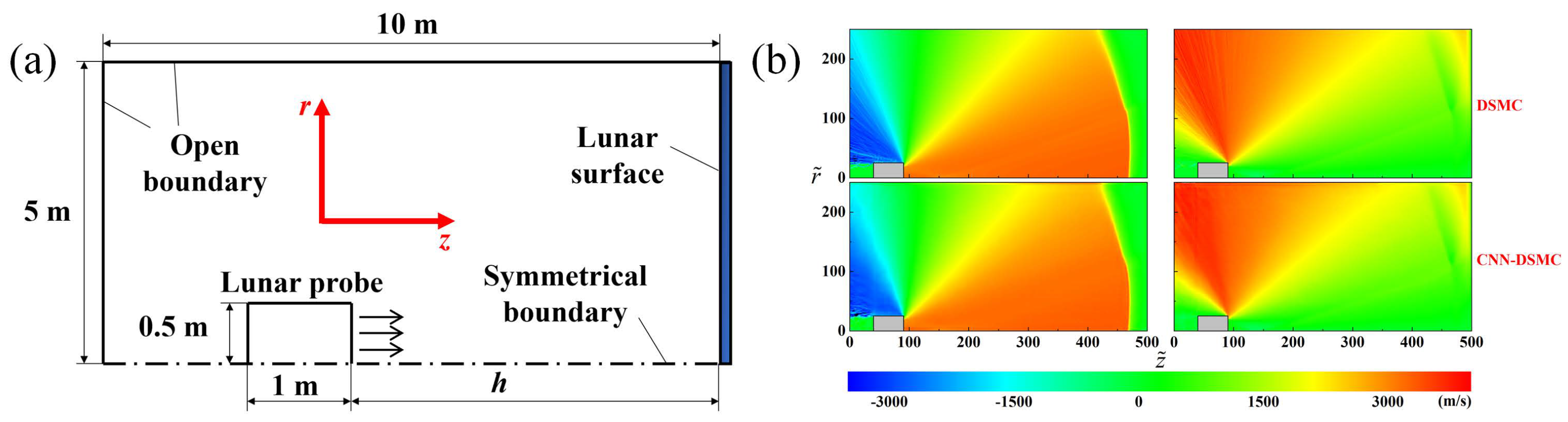
4.1. Fast Prediction of the Vacuum Plume Using Deep Learning

Although the DSMC provides an accurate way to assess the vacuum plume, its application is dramatically limited by computational efficiency, especially for large-scale spacecraft (e.g., >1 m). For instance, it takes approximately 100 h to simulate a plume flow in a scenario of the Lunar landing with 240 cores of the Intel Xeon E5-2670 v3 CPU (2.3 GHz) [143]. Researchers have put much effort into the application of deep learning (DL) in the continuum flow and have demonstrated its applicability and efficiency [144,145,146]. We are, then, motivated and preliminary explore the feasibility of DL for the vacuum plume prediction (rarefied flow) using convolutional neural networks (CNN).
The plume and its effects are usually assessed by the DSMC at each altitude (h, ranging from 30 m to 0 m) during a Lunar probe descending process, which is time-consuming and costly. Here, we expect that the plume assessment at arbitrary altitudes can be obtained from a trained model using the DL, where the model is trained by a limited set of DSMC results. We employ CNN to extract features from training (DSMC) results and then predict the vacuum plume, and thus, this method is termed as CNN-DSMC. The prediction using CNN-DSMC is realized by the data preprocessing and training process shown in Figure 18. In the preprocessing, the shape information and the boundary conditions of the vacuum plume simulation model are transformed into the signed distance function (SDF) and identifier matrix (IM), being the initial input of the training dataset. The initial output of the training dataset is the velocity field obtained by the DSMC solver (PWS of Beihang University). For the training process, the training dataset is fed into CNN to optimize the net parameters of CNN-DSMC. After training, the trained networks can be obtained as
U , V = f ( SDF , IM ) ,
where U and V refer to velocities. The mapping relationship between the plume velocity and the input information is then constructed by Euqtion (4). Note that we utilize (U, V) to demonstrate the CNN-DSMC, and the parameters, such as density, temperature, and mass fraction, can be combined on the left of Equation (4) and then be predicted by CNN-DSMC.
Figure 19a displays the whole network architecture for CNN-DSMC. The input of the CNN-DSMC is the shape information and the boundary conditions, and the velocity field can be constructed from the input and the networks. The networks are built based on U-net, which is a kind of CNN proposed for biomedical image segmentation. As illustrated in Figure 19, there is an encoder consisting of 7 convolution blocks (blue squares), and two decoders consisting of 14 deconvolution blocks (orange squares). Each convolution or deconvolution block comprises three convolution or deconvolution layers and a max pooling or max unpooling layer, as shown in Figure 19b. A single convolution (deconvolution) layer contains the process of convolution (deconvolution), Relu activation, and batch normalization. In the training process, the loss function is the mean square error (MSE) of N velocity components,
Loss = 1 N N m = 1 U t U p 2 + N m = 1 V t V p 2 ,
where U t and V t are the axial and radial velocities simulated by DSMC, respectively; U p and V p stand for the axial and radial velocities predicted by CNN-DSMC, respectively. Again, the loss function is supposed to established according to the parameters that need to be predicted.
Figure 20a shows the computational domain and boundary conditions of the two-dimensional axisymmetric case. The number of training datasets simulated by DSMC (PWS software) is 18. The altitude of the training dataset ranges from 0.5 m to 9.0 m, with a step of 0.5 m. The altitude of the test dataset is h = 8.2 m. The results simulated by DSMC and predicted by CNN-DSMC are shown in Figure 20b. The average errors between the results obtained by the DSMC and CNN-DSMC are 1% and 0.7% for the axial (U) and radial (V) velocities, respectively, suggesting that the simulated and predicted results are consistent. Meanwhile, the shock waves at z 460 are predicted well, showing that the CNN-DSMC method is feasible in predicting the vacuum plume [147].
The efficiency is dramatically enhanced by the CNN-DSMC. The run time of DSMC is approximately 21,745 s, counted as the average time of a DMSC case shown in Figure 20a running on 24 cores of the Intel Xeon E5-2670 v3 CPU (2.3 GHz). The training time is approximately 2000 s with the same CPU and an Nvidia Quadro RTX-A6000 GPU. The run time of CNN-DSMC for the case shown in Figure 20 is 1.47 s. According to the properties of CPU and GPU employed, we estimated the FLOPs (floating point operations per second) used by the two methods. The total number of FLOPs of the DSMC and CNN-DSMC are in the orders of 10 4 TFLOPs and 10 1 TFLOPs, respectively. The FLOPs taken by the CNN-DSMC are significantly reduced, thereby decreasing the run time. This speedup is primarily attributed to the CNN-DSMC algorithm due to the fewer FLOPs utilized.
In addition, we attempt to use the developed CNN-DSMC method for the three-dimensional simulations (CNN-DSMC-3D), as displayed in Figure 21a. The identical method and process described above are employed. The predicted results are also in agreement with the simulation results, and its average error is approximately 6%, which is larger than that of two-dimensional results shown in Figure 21b. A single case of the two-dimensional simulation is typically a few hundred MB, while that of the three-dimensional simulation can be up to tens of GB. Taking into account the fact that the video memory of our GPU is 48 GB, the CNN-DSMC-3D model is trained with only several cases, which has an adverse impact on the model’s accuracy. Similarly, the total number of FLOPs of the DSMC and CNN-DSMC-3D are estimated and are in the orders of o( 10 6 ) TFLOPs and o( 10 2 ) TFLOPs, respectively. As a result, the run time of three-dimensional CNN-DSMC is approximately 4 s, as the training time is not considered, which is far less than the run time of the DSMC (≈100 h) under the same conditions.
We successfully used the CNN-DSMC method to predict the vacuum plume. However, the accuracy of three-dimensional cases needs to be improved. Most importantly, the boundary conditions of the training and test datasets utilized above are the same. It is vital to be investigated the CNN-DSMC method with the different boundary conditions between the training and test datasets for further practical applications.

4.2. Plume-Surface Interaction

Researchers have put much effort into the vacuum plume for over half a century. The plume flow of gas and plasma has been extensively investigated, and it can be accurately evaluated by both experiments and simulations. Still, the plume–surface interactions remain unclear, leading to an underestimation or overestimation of the plume effects.
The energy and momentum transfer of plasma–surface interactions, which determines the heating flux and force/torque on the surface, is generally modeled by the specular reflection, diffuse reflection, Maxwell, and CLL models [12,13]. The Maxwell model assumes that a fraction of the incident molecules reflect diffusely, and the remaining fraction reflects specularly, where accommodation coefficients describe the degree of accommodation of the incident normal momentum, tangential momentum, and total kinetic energy to those of the surface, which are defined as [13]
σ n = p i p r p i p w , σ t = τ i τ r τ i , α = q i q r q i q w ,
where σ n , σ t and α are the normal momentum accommodation coefficient, tangential momentum accommodation coefficient, and thermal accommodation coefficient, respectively. The CLL model provides a continuous spectrum of behavior from the specular reflection at one end to diffuse reflection with complete energy accommodation at the other and produces physically realistic distributions describing the directions and energies of the re-emitted molecules. The CLL model involves the normal component of translational energy α n and the tangential momentum component σ t [142]. The Maxwell and the CLL models need prior knowledge of the accommodation coefficients. Although the accommodation coefficients of rarefied gas–surface interactions have been widely investigated through hot-wire and parallel-plate methods [148], researchers have mainly focused on the static rarefied gas for micro-channels. By contrast, the (dynamic) rarefied gas in the vacuum plume has a relatively large velocity, and little relevant data are reported. Due to the lack of accommodation coefficients, the heating flux is practically evaluated by assuming that α = 1 for the safety, possibly differing from the actual situation and complicating the spacecraft design. Consequently, attention to measurement methods and measurement of accommodation coefficients of high-speed rarefied gas needs to be paid.
Moreover, to our best knowledge, the accommodation coefficients of plasma–surface interactions for electrical thrusters have only been studied by Shuvalov [149,150] and Liu et al. [142]. Shuvalov [149,150] experimentally explored the accommodation coefficients as a surface immersed in ionized gas flow with low energy (<100 eV). Liu et al. [142] theoretically, experimentally, and numerically explored the σ n as a plasma plume flow with the energy of 1000 eV (Xe + ) impacted on an immersed aluminum surface vertically, and the measured result is σ n 1.0 . In comparison, Shuvalov [149,150] introduced that σ n 0.8 when a single crystal of Si, which is next to Al in the periodic table, is bombarded by Xe + with the energy of about 68.8 eV, and σ n 0.9 for the Xe + with the energy of about 100 eV impinging with an aluminized polymer film. The accommodation coefficients increase as the energy of incident particles for metal targets increases. It can be interpreted by assuming that the particles penetrate progressively deeper into the solid as their kinetic energy increases [151]. From this perspective, the Maxwell and CLL proposed for the gas–surface interactions involving the reflection are no longer applicable for the plasma–surface interactions, and new models need to be suggested.
The gas adsorption appears after gas–surface interactions, which contaminates the solid surfaces (i.e., the gas contamination effect). It has been widely studied under the standard atmospheric pressure or high pressure, and the Langmuir model, Dubinin–Radushkevich model, Brunauer–Emmett–Teller model, and universal model have been developed [83,84]. However, the gas contamination produced by the vacuum plume takes place in a low-pressure condition. Su et al. [83] and Wu et al. [84], therefore, experimentally studied the adsorption of CO 2 and H 2 O at different ambient (low) pressure and surface temperature using QCMs. The results show that the gas adsorption is significantly enhanced by the high pressure and low surface temperature, as shown in Figure 22. It varies with the gas species as well. For example, the saturation adsorption mass of CO 2 and H 2 O at the ambient pressure of 20 Pa and the surface temperature of 233 K are 100 ng/cm 2 and 200 ng/cm 2 , respectively. Based on the experimental fitting, Wu et al. [84] proposed a model correlating the saturation adsorption mass with the ambient pressure (p) and surface temperature (T) for the vacuum plume,
m = ( a 1 T + a 0 ) b M c p 1 + b M c p ,
where a 1 , a 0 , and b M c are experimental fitting parameters. For a bipropellant thruster with the propellant of monomethylhydrazine and nitrogen tetroxide (MMH/NTO), the residue species include H 2 O, HONO, CH 3 ONO 2 , CH 3 ONO, CH 3 N 3 , CH 3 OH, CH 3 NH 2 , CH 2 , N 2 O, NO, N 2 , etc. [152]. As a result, the adsorption of different gases or mixtures simulating the actual exhausted gas under low pressure remains. The quartz crystal of QCMs is coated with gold, and the results reported in Refs. [83,84] are essentially the gas–gold surface interactions. The effect of the surface needs to be noticed in the future with the development of measurement technology.
As revealed on the ground test and on-orbit test of MMH/NTO thrusters (especially with the pulse model), the droplets depositing the surface are captured after plume–surface interactions (Figure 23), which is another type of contamination induced by the vacuum plume (liquid contamination) [7]. They are found to be the residue (monomethylhydrazinium nitrate, MMH·HNO 3 ) resulting from the incomplete combustion of propellants [153,154,155]. The ground and on-orbit tests display that the aforementioned droplets can persist in a vacuum environment for long periods of time rather than (flash) evaporation (>24 h), suggesting that MMH·HNO 3 is the ionic liquid instead of the molecular liquid [152]. The drop impact on solid surfaces has been widely studied with molecular liquid droplets (such as water and ethanol) [156,157,158,159,160,161]; however, it has hardly been investigated with ionic liquids. We conducted some tests with ionic liquids under atmospheric pressure and low impact velocity. Compared with the molecular liquids, the phase diagram and maximum spreading diameter are dramatically altered by the ionic liquids. The impact velocity reported in Refs. [156,157,158,159,160,161] is basically generated by the free-fall motion, which is far less than that of droplets in the plume accelerated by the high-speed gas flow [5,6]. The splashing can be triggered, as the impact velocity is sufficiently high [159], resulting in the secondary droplets and additional contamination and complicating the analysis of the plume-induced contamination. The surface damage caused by the high-speed impact is observed in the on-orbit test, as shown in Figure 23 [7], which is not recorded with the low impact velocity [159]. Hence, to fully describe the contamination, high-speed ionic liquid drop–surface interactions at a vacuum environment should be studied further. Furthermore, ionic liquids are generally poor-to-moderate electrical conductors, and their influence on sensitive surfaces (e.g., solar panels) is supposed to be a concern.

4.3. Plume–Lunar/Mars Regolith Interaction

In addition to the plume effects mentioned before, massive dust particles are ejected due to plume–Lunar/Mars regolith interactions during the probe landing on extraterrestrial bodies, thereby blocking the vision and damaging the sensors of the probe. Moreover, the crater formed by the dust ejection could threaten the landing safety of probes. The plume–Lunar dust interactions were investigated for the Apollo program by Land et al. in the 1960s [162,163]. The scaled nozzles with the propellant of air [162] and helium [163] were employed. An X-ray system was used to detect the evolution of the crater induced by the plume. The light attenuation was measured to explore the pilot’s visibility. The effects of thrust, decent velocity, decent height, and regolith particle sizes on the crater and visibility were investigated.
Recently, the plume–Lunar dust interactions were further studied according to the image sequences captured by the cameras positioned on the probes of the Apollo program [164] and the Change’E program [165]. Meanwhile, numerical research has been conducted to simulate the crater caused by erosion and the dust particles triggered by high-speed gas flow [166,167,168,169,170,171]. However, the mechanism underlying this process has not been fully understood yet because of the limited practical and experimental data [172]. Motivated by the Artemis program, a series of systemic experiments have been performed, and preliminary results have been reported, as shown in Figure 24 [172,173,174,175]. Figure 24a,b illustrates the corresponding diagnostic system built by NASA. The tests were conducted with a nozzle fed with the heated N 2 (500 K). Various high-speed cameras are used to record the dynamics of the crater and ejected dust particles from the side and top views. The influence of nozzle height, ambient pressure, mass flow rate, and regolith simulants is investigated. A typical crater observed from the side and top views is shown in Figure 24c.
We performed a similar test using a conical nozzle fed with the cold N 2 . The regolith simulants are aluminum oxide particles with a characteristic diameter of 100 μ m. The dynamics of the crater and particles are monitored by high-speed cameras and PIV. The results show that the particles can be traced by the PIV, as shown in Figure 25. Given the maturity of the PIV, it is suggested to be used to detect the ejected particle velocity. Moreover, we found that the camera view is readily blocked by the massive ejected particles. It is challenging to monitor the crater formation and erosion rate. Therefore, the setup shown in Figure 24 adopts a transparent splitter plate to visualize the crater dynamics. However, the influence of the splitter plate on the test needs to be further claimed. Overall, more technologies are expected to be introduced to measure the crater and ejected particle dynamics quantitatively, such as X-ray imaging and PDPA.
All the reported experimental results were obtained with a single thruster fed with the cold gas [162,163] or heated N 2 (500 K) [172,173,174,175], differing from the piratical thrusters utilized on the probes. The plume velocity of the cold gas thruster is far less than that of the MMH/NTO thrusters; several thrusters fire simultaneously during the landing. Consequently, to match the actual scenarios, a single thruster and a clustered thrusters shrunken from the piratical thrusters (e.g., MMH/NTO thruster) is supposed to be utilized to reveal the underlying mechanism of plume–Lunar/Mars regolith interactions. We are systematically performing the relevant tests and will report later.

5. Conclusions

Chemical and electrical thrusters are crucial devices for spacecraft in aerospace. As the thruster fires, its exhaust, known as the vacuum plume, impinges on the spacecraft’s surface, causing the energy and momentum transfer due to plume–surface interactions, resulting in unexpected heating load, force/torque, contamination, erosion, and sputtering. These harmful effects can reduce spacecraft performance or threaten spacecraft safety. Consequently, researchers have put much effort into assessing the vacuum plume and its effect. In this review, the ground test and numerical research methods on the vacuum plume of chemical and electrical thrusters are presented. The challenge and difference in the vacuum environment (chamber) created for the ground test of two kinds of thrusters are introduced. The measurement of plume flow and its effect using invasive and non-invasive technologies are described. For the gas plume flow characterized by the rarefied flow, the hybrid CFD-DSMC algorithm is suggested to simulate the plume flow and its effects for chemical thrusters. However, the plasma plume flow produced by electrical thrusters is more complex since it involves charged particles, and hence, the PIC-DSMC algorithm is recommended. In particular, several topics for future research are proposed based on the requirements of high efficiency and accuracy in engineering applications.

Author Contributions

Conceptualization, G.C. and L.L.; methodology, L.L., G.L. and H.W.; software, B.H. and G.C.; validation, G.C. and L.L.; investigation, G.C., L.L., B.H. and W.W.; resources, G.C. and L.L.; writing—original draft preparation, G.C. and L.L.; writing—review and editing, G.C., L.L., B.H. and W.W.; visualization, L.L.; supervision, G.C.; project administration, G.C.; funding acquisition, G.C. All authors have read and agreed to the published version of the manuscript.

Funding

This research was funded by National Science Foundation of China under grant number 51676010.

Institutional Review Board Statement

Not applicable.

Informed Consent Statement

Not applicable.

Data Availability Statement

Not applicable.

Acknowledgments

We appreciate our colleagues who made outstanding contributions to the research of the vacuum plume but are not listed as the authors, such as Zhang jianhua, Yuan junya, Wang wenlong, He xiaoying, Ke Weina, Tang zhenyu, Wang hongyue, Su wei, Han yue, Zhang mingxing, Wu jing, Shang shengfei, Zhou hao, Su Yang, Zheng Hongru, Ren xiang, Jiang Qihan, Wu Chenggeng, Zhang Baiyi, Gao Da, Li Xinjie, Chen Yatao, and Chen Chen.

Conflicts of Interest

The authors declare no conflict of interest. The funders had no role in the design of the study; in the collection, analyses, or interpretation of data; in the writing of the manuscript; or in the decision to publish the results.

References

  1. He, B.; Zhang, J.; Cai, G. Research on vacuum plume and its effects. Chin. J. Aeronaut. 2013, 26, 27–36. [Google Scholar] [CrossRef] [Green Version]
  2. He, B.; He, X.; Zhang, M.; Cai, G. Plume aerodynamic effects of cushion engine in lunar landing. Chin. J. Aeronaut. 2013, 26, 269–278. [Google Scholar] [CrossRef] [Green Version]
  3. Dettleff, G.; Grabe, M. Basics of Plume Impingement Analysis for Small Chemical and Cold Gas Thrusters. In Proceedings of the Models and Computational Methods for Rarefied Flows, RTO/NATO, Rhode St. Genese, Belgium, 24–28 January 2011. [Google Scholar]
  4. Lehrer, S. Microthrust engines for the investigation of spacecraft surface heating. J. Spacecr. Rockets 1966, 3, 983–988. [Google Scholar] [CrossRef]
  5. Trinks, H.; Hoffman, R. Experimental investigation of bipropellant exhaust plume flowfield, heating, and contamination, and comparison with the CONTAM computer model predictions. In Proceedings of the 18th Thermophysics Conference, Montreal, QC, Canada, 1–3 July 1983; American Institute of Aeronautics and Astronautics: Reston, VA, USA, 1983. [Google Scholar]
  6. Trinks, H.; Kaelsch, I. Exhaust plume effects of small thrusters on spacecraft surfaces. In Proceedings of the 22nd Thermophysics Conference, Honolulu, HI, USA, 8–10 June 1987; American Institute of Aeronautics and Astronautics: Reston, VA, USA, 1987. [Google Scholar]
  7. Grabe, M.; Soares, C.E. Status and future of research on plume induced contamination. In Proceedings of the 70th International Astronautical Congress, Washington, DC, USA, 21–25 October 2019; International Astronautical Federation: Paris, France, 2019. [Google Scholar]
  8. Whitmore, S.A. Plume Contamination Measurements of an Additively Printed, Green-Propellant Hybrid Thruster. J. Propuls. Power 2022, 38, 1–15. [Google Scholar] [CrossRef]
  9. He, X.; He, B.; Cai, G. Simulation of two-phase plume field of liquid thruster. Sci. China Technol. Sci. 2012, 55, 1739–1748. [Google Scholar] [CrossRef]
  10. French, E.P. Effect of rocket exhausts on infrared planet sensors. J. Spacecr. Rockets 1966, 3, 849–853. [Google Scholar] [CrossRef]
  11. Soares, C.; Olsen, R.; Steagall, C.; Huang, A.; Mikatarian, R.; Myers, B.; Koontz, S.; Worthy, E. Improvements in Modeling Thruster Plume Erosion Damage to Spacecraft Surfaces. In Proceedings of the 13th International Symposium on Materials in the Space, Pau, France, 22–26 June 2015; National Aeronautics and Space Administration: Washington, DC, USA, 2015. [Google Scholar]
  12. Bird, G.A. Molecular Gas Dynamics and the Direct Simulation of Gas Flows; Oxford University Press: Oxford, UK, 1994. [Google Scholar]
  13. Shen, C. Rarefied Gas Dynamics: Fundamentals, Simulations and Micro Flows; Springer Science & Business Media: Heidelberg, Germany, 2006. [Google Scholar]
  14. Boynton, F.P. Exhaust plumes from nozzles with wall boundary layers. J. Spacecr. Rockets 1968, 5, 1143–1147. [Google Scholar] [CrossRef]
  15. Shaw, L.; Hickman, R. Comparison of predicted and measured low-density plume impingement effects. J. Spacecr. Rockets 1969, 6, 1338–1341. [Google Scholar] [CrossRef]
  16. Arnett, G. Lunar Excursion Module RCS Engine Vacuum Chamber Contamination Study; Technical Report; National Aeronautics and Space Administration: Washington, DC, USA, 1969.
  17. Krewski, T.; Lacinski, T. Comparison of full-and sub-scale plume impingement tests in a vacuum. In Proceedings of the 6th Aerodynamics Testing Conference, Albuquerque, NM, USA, 10–12 March 1971; American Institute of Aeronautics and Astronautics: Reston, VA, USA, 1971. [Google Scholar]
  18. Clark, L.V. Experimental Investigation of Close-Range Rocket-Exhaust Impingement on Surfaces in a Vacuum; National Aeronautics and Space Administration: Washington, DC, USA, 1970.
  19. Cai, C. Theoretical and Numerical Studies of Plume Flows in Vacuum Chambers. Ph.D. Thesis, University of Michigan, Ann Arbor, MI, USA, 2005. [Google Scholar]
  20. Grabe, M.; Dettlef, G.; Hannemann, K. Comparison of computed free thruster plume expansion to experiments. In Proceedings of the Space Propulsion Conference 2014, Cologne, Germany, 19–22 May 2014; European Space Agency: Paris, France, 2014. [Google Scholar]
  21. Lee, K.H. Numerical comparison of exhaust plume flow behaviors of small monopropellant and bipropellant thrusters. PLoS ONE 2017, 12, e0176423. [Google Scholar] [CrossRef] [Green Version]
  22. Lee, K.H. Plume influence analysis of small bipropellant thruster on solar array of GEO satellite. PLoS ONE 2018, 13, e0199667. [Google Scholar] [CrossRef]
  23. Lee, K.H. Plume simulation of liquid apogee engine for GEO satellite using parallel DSMC method. Comput. Fluids 2020, 208, 104612. [Google Scholar] [CrossRef]
  24. Markelov, G.; Brand, R.; Ibler, G.; Supper, W. Numerical assessment of plume heat and mechanical loads and contamination on multi-layer insulation in hard vacuum. Vacuum 2012, 86, 889–894. [Google Scholar] [CrossRef]
  25. Bernard, F.; Iollo, A.; Puppo, G. Simulation of particle dynamics for rarefied flows: Backflow in thruster plumes. Eur. J.-Mech.-B Fluids 2017, 63, 25–38. [Google Scholar] [CrossRef] [Green Version]
  26. Lee, K.H. Numerical simulation on thermal and mass diffusion of MMH–NTO bipropellant thruster plume flow using global kinetic reaction model. Aerosp. Sci. Technol. 2019, 93, 104882. [Google Scholar] [CrossRef]
  27. Lee, K.H. Comparison study of exhaust plume impingement effects of small mono-and bipropellant thrusters using parallelized DSMC method. PLoS ONE 2017, 12, e0179351. [Google Scholar] [CrossRef] [Green Version]
  28. Dettleff, G. Plume flow and plume impingement in space technology. Prog. Aerosp. Sci. 1991, 28, 1–71. [Google Scholar] [CrossRef]
  29. Slbulkin, M.; Gallaher, W. Far-field approximation for a nozzle exhausting into a vacuum. AIAA J. 1963, 1, 1452–1453. [Google Scholar] [CrossRef]
  30. Draper, J.S.; Hill, J.A. Analytical approximation for the flow from a nozzle into a vacuum. J. Spacecr. Rockets 1966, 3, 1552–1554. [Google Scholar] [CrossRef]
  31. Luce, R.W.; Jarvinen, P.O. An approximate method for predicting plume sizes for nozzle flow into still air. AIAA J. 1968, 6, 182–183. [Google Scholar] [CrossRef]
  32. Maddox, A. Impingement of underexpanded plumes on adjacent surfaces. J. Spacecr. Rockets 1968, 5, 718–724. [Google Scholar] [CrossRef]
  33. Brook, J.W. Far field approximation for a nozzle exhausting into a vacuum. J. Spacecr. Rockets 1969, 6, 626–628. [Google Scholar] [CrossRef]
  34. Plähn, K.; Dettleff, G. Modelling of N2-thruster Plumes based on Experiments in STG. AIP Conf. Proc. 2001, 585, 848–855. [Google Scholar]
  35. Cai, C.; Sun, Q.; Vanderwyst, A. Analytical exact solutions for unsteady collisionless plume flows in a vacuum. Acta Astronaut. 2013, 91, 218–227. [Google Scholar] [CrossRef] [Green Version]
  36. Zhu, Y.; Zhong, C.; Xu, K. GKS and UGKS for High-Speed Flows. Aerospace 2021, 8, 141. [Google Scholar] [CrossRef]
  37. Cai, C. Gaskinetic modeling on dilute gaseous plume impingement flows. Aerospace 2016, 3, 43. [Google Scholar] [CrossRef] [Green Version]
  38. O’Reilly, D.; Herdrich, G.; Kavanagh, D.F. Electric propulsion methods for small satellites: A review. Aerospace 2021, 8, 22. [Google Scholar] [CrossRef]
  39. Miguel, S.; Kan, X.; Ningfei, W.; Ning, G.; Zun, Z. Ion engine grids: Function, main parameters, issues, configurations, geometries, materials and fabrication methods. Chin. J. Aeronaut. 2018, 31, 1635–1649. [Google Scholar] [CrossRef]
  40. Lev, D.; Myers, R.M.; Lemmer, K.M.; Kolbeck, J.; Koizumi, H.; Polzin, K. The technological and commercial expansion of electric propulsion. Acta Astronaut. 2019, 159, 213–227. [Google Scholar] [CrossRef]
  41. Potrivitu, G.C.; Sun, Y.; Rohaizat, M.W.A.b.; Cherkun, O.; Xu, L.; Huang, S.; Xu, S. A review of low-power electric propulsion research at the Space Propulsion Centre Singapore. Aerospace 2020, 7, 67. [Google Scholar] [CrossRef]
  42. Shang, S.; Cai, G.; Zhu, D.; He, B. An empirical formula for Ez in the modified Sigmund formula for low energy heavy ion bombardment. Vacuum 2016, 125, 192–204. [Google Scholar] [CrossRef]
  43. Hallouin, T.; Mazouffre, S. Far-field plume characterization of a 100-W class Hall thruster. Aerospace 2020, 7, 58. [Google Scholar] [CrossRef]
  44. Boyd, I.D. Review of hall thruster plume modeling. J. Spacecr. Rockets 2001, 38, 381–387. [Google Scholar] [CrossRef] [Green Version]
  45. Boyd, I.D. Numerical modeling of spacecraft electric propulsion thrusters. Prog. Aerosp. Sci. 2005, 41, 669–687. [Google Scholar] [CrossRef]
  46. Zhang, Z.; Zhang, Z.; Xu, S.; Ling, W.Y.L.; Ren, J.; Tang, H. Three-dimensional measurement of a stationary plasma plume with a Faraday probe array. Aerosp. Sci. Technol. 2021, 110, 106480. [Google Scholar] [CrossRef]
  47. Zhang, Z.; Tang, H.; Kong, M.; Zhang, Z.; Ren, J. Electron temperature measurement in Maxwellian non-isothermal beam plasma of an ion thruster. Rev. Sci. Instrum. 2015, 86, 23506. [Google Scholar] [CrossRef]
  48. Zhang, Z.; Tang, H.; Zhang, Z.; Wang, J.; Cao, S. A retarding potential analyzer design for keV-level ion thruster beams. Rev. Sci. Instrum. 2016, 87, 123510. [Google Scholar] [CrossRef]
  49. Liu, L.; Cai, G.; You, F.; Ren, X.; Zheng, H.; He, B. Improving the viability and versatility of the E× B probe with an active cooling system. Rev. Sci. Instrum. 2018, 89, 43502. [Google Scholar] [CrossRef]
  50. VanGilder, D.B.; Font, G.I.; Boyd, I.D. Hybrid Monte Carlo-particle-in-cell simulation of an ion thruster plume. J. Propuls. Power 1999, 15, 530–538. [Google Scholar] [CrossRef] [Green Version]
  51. Zheng, H.; Cai, G.; Wang, H.; Liu, L.; He, B. Three-dimensional particle simulation of ion thruster plume flows with EX-PWS. Plasma Sci. Technol. 2018, 20, 105501. [Google Scholar] [CrossRef] [Green Version]
  52. Johnson, I.K.; Santiago, G.; Li, J.; Baldwin, J. 100,000 hrs of On-Orbit Electric Propulsion and Maxar’s First Electric Orbit Raising. In Proceedings of the AIAA Scitech 2020 Forum, Orlando, FL, USA, 6–10 January 2020; American Institute of Aeronautics and Astronautics: Reston, VA, USA, 2020. [Google Scholar]
  53. Trottenberg, T.; Bansemer, F.; Böttcher, S.; Feili, D.; Henkel, H.; Hesse, M.; Kersten, H.; Krüger, T.; Laube, J.; Lazurenko, A.; et al. An in-flight plasma diagnostic package for spacecraft with electric propulsion. EPJ Tech. Instrum. 2021, 8, 16. [Google Scholar] [CrossRef]
  54. Zhang, M.; Cai, G.; Tang, Z.; He, B.; Zhang, W.; Shu, Y. Experimental and numerical research on the diversion effect of a conic flame deflector for a lunar module ascent stage. J. Aerosp. Eng. 2016, 29, 4016021. [Google Scholar] [CrossRef]
  55. Zhang, M.; Cai, G.; He, B.; Tang, Z.; Zhou, H. Experimental and numerical analysis of the heat flux characteristic of the plume of a 120-N thruster. Sci. China Technol. Sci. 2019, 62, 1854–1860. [Google Scholar] [CrossRef]
  56. Wu, J.; Cai, G.; He, B.; Zhou, H. Experimental and numerical investigations of vacuum plume interaction for dual hydrogen/oxygen thrusters. Vacuum 2016, 128, 166–177. [Google Scholar] [CrossRef]
  57. Grabe, M.; Dettleff, G.; Hannemann, K. Impact of nozzle separation on the plumes of two parallel thrusters. AIP Conf. Proc. 2016, 1786, 170005. [Google Scholar]
  58. Dettleff, G.; Plähn, K.; Dettleff, G.; Plaehn, K. Initial experimental results from the new DLR-high vacuum plume test facility STG. In Proceedings of the 33rd Joint Propulsion Conference and Exhibit, Seattle, WA, USA, 6–9 July 1997; American Institute of Aeronautics and Astronautics: Reston, VA, USA, 1997. [Google Scholar]
  59. Lutfy, F.; Vargo, S.; Muntz, E.; Ketsdever, A. The David P.Weaver Collaborative High Altitude Flow Facility’s CHAFF-4 for studies of spacecraft propulsion plumes and contamination. In Proceedings of the 34th AIAA/ASME/SAE/ASEE Joint Propulsion Conference and Exhibit, Cleveland, OH, USA, 13–15 July 1998; American Institute of Aeronautics and Astronautics: Reston, VA, USA, 1998. [Google Scholar]
  60. Wang, W.; Cai, G.; Zhou, J. Large-scale vacuum vessel design and finite element analysis. Chin. J. Aeronaut. 2012, 25, 189–197. [Google Scholar]
  61. Cai, G.; Ling, G.; He, B. An introduction to the novel vacuum plume effects experimental system. Sci. China Technol. Sci. 2016, 59, 953–960. [Google Scholar] [CrossRef]
  62. Plesik, E.; Koppang, R.; Simkin, D. Rocket-exhaust impingement on a flat plate at high vacuum. J. Spacecr. Rockets 1966, 3, 1650–1657. [Google Scholar] [CrossRef]
  63. Wu, J.; Bitter, M.; Cai, G.; He, B.; Kaehler, C. Investigation on aerodynamic force effect of vacuum plumes using pressure-sensitive paint technique and CFD-DSMC solution. Sci. China Technol. Sci. 2017, 60, 1058–1067. [Google Scholar] [CrossRef]
  64. Wu, J.; Kong, D.; Zhang, P.; Huang, F.; Cai, G. Characterization of pressure-sensitive paint based on mesoporous silica particles under near-vacuum conditions. Sens. Actuators A Phys. 2021, 330, 112844. [Google Scholar] [CrossRef]
  65. Wu, J.; Chen, Y.; Huang, F. Effects of a gaseous atmosphere on the pressure sensitivity and constancy of pressure-sensitive paints. IEEE Sens. J. 2022. [Google Scholar] [CrossRef]
  66. Wu, J.; Kong, D.; Huang, F.; Cai, G.; Shi, A.; Chen, Y. Pressure-sensitivity stability of poly [1-(trimethylsilyl)-1-propyne]-based pressure-sensitive paint for low-pressure conditions. Measurement 2022, 196, 111012. [Google Scholar] [CrossRef]
  67. Weng, H.; Cai, G.; Liu, L.; Zheng, H.; Shang, S.; He, B. A momentum flux measuring instrument with the variable-range for exhaust plume. AIP Adv. 2018, 8, 85027. [Google Scholar] [CrossRef] [Green Version]
  68. Benedikt, J.; Kersten, H.; Piel, A. Foundations of measurement of electrons, ions and species fluxes toward surfaces in low-temperature plasmas. Plasma Sources Sci. Technol. 2021, 30, 33001. [Google Scholar] [CrossRef]
  69. Varade, V.; Agrawal, A.; Prabhu, S.; Pradeep, A. Velocity measurement in low Reynolds and low Mach number slip flow through a tube. Exp. Therm. Fluid Sci. 2015, 60, 284–289. [Google Scholar] [CrossRef]
  70. Liu, L.; Nan, X.; Lin, F. Flow measurements near the open surfaces of single circumferential grooves in a low-speed axial compressor. Aerosp. Sci. Technol. 2018, 78, 531–541. [Google Scholar] [CrossRef]
  71. Yüceil, K.B. A comparison of PIV and interferometric Rayleigh scattering measurements in the near field of underexpanded sonic jets. Aerosp. Sci. Technol. 2017, 67, 31–40. [Google Scholar] [CrossRef]
  72. Song, A.; Qin, Z.; Li, J.; Li, M.; Huang, K.; Yang, Y.; Wang, N. Real-Time Plume Velocity Measurement of Solid Propellant Rocket Motors Using TDLAS Technique. Propellants Explos. Pyrotech. 2021, 46, 636–653. [Google Scholar] [CrossRef]
  73. Jiang, L.; Sislian, J. Velocity and density measurements in supersonic high-temperature exhaust plumes. AIAA J. 1998, 36, 1216–1222. [Google Scholar] [CrossRef]
  74. Hall, C.A.; Ramsey, M.C.; Knaus, D.A.; Pitz, R.W. Molecular tagging velocimetry in nitrogen with trace water vapor. Meas. Sci. Technol. 2017, 28, 85201. [Google Scholar] [CrossRef]
  75. Huffman, R.; Elliott, G. An experimental investigation of accurate particle tracking in supersonic, rarefied, axisymmetric jets. In Proceedings of the 47th AIAA Aerospace Sciences Meeting including The New Horizons Forum and Aerospace Exposition, Orlando, FL, USA, 5–8 January 2009; American Institute of Aeronautics and Astronautics: Reston, VA, USA, 2009. [Google Scholar]
  76. Ribarov, L.; Wehrmeyer, J.; Hu, S.; Pitz, R. Multiline hydroxyl tagging velocimetry measurements in reacting and nonreacting experimental flows. Exp. Fluids 2004, 37, 65–74. [Google Scholar] [CrossRef]
  77. Pitz, R.W.; Lahr, M.D.; Douglas, Z.W.; Wehrmeyer, J.A.; Hu, S.; Carter, C.D.; Hsu, K.Y.; Lum, C.; Koochesfahani, M.M. Hydroxyl tagging velocimetry in a supersonic flow over a cavity. Appl. Opt. 2005, 44, 6692–6700. [Google Scholar] [CrossRef]
  78. Ramsey, M.; Pitz, R.; Jenkins, T.; Matsutomi, Y.; Yoon, C.; Anderson, W. Planar 2D velocity measurements in the cap shock pattern of a thrust optimized rocket nozzle. Shock Waves 2012, 22, 39–46. [Google Scholar] [CrossRef]
  79. Danehy, P.M.; O’Byrne, S.; Frank, A.; Houwing, P.; Fox, J.S.; Smith, D.R. Flow-tagging velocimetry for hypersonic flows using fluorescence of nitric oxide. AIAA J. 2003, 41, 263–271. [Google Scholar] [CrossRef]
  80. Zhang, S.; Yu, X.; Yan, H.; Huang, H.; Liu, H. Molecular tagging velocimetry of NH fluorescence in a high-enthalpy rarefied gas flow. Appl. Phys. B Lasers Opt. 2017, 123, 1–7. [Google Scholar] [CrossRef] [Green Version]
  81. Lackner, M. Tunable diode laser absorption spectroscopy (TDLAS) in the process industries—A review. Rev. Chem. Eng. 2007, 23, 65–147. [Google Scholar] [CrossRef]
  82. Sappey, A.D.; Masterson, P.; Howell, J.; Estes, M.; Owenby, D.; Sutherland, L. Tomographic reconstruction of multipath tunable diode laser spectroscopy measurements in turbine engines. J. Propuls. Power 2014, 30, 24–28. [Google Scholar] [CrossRef]
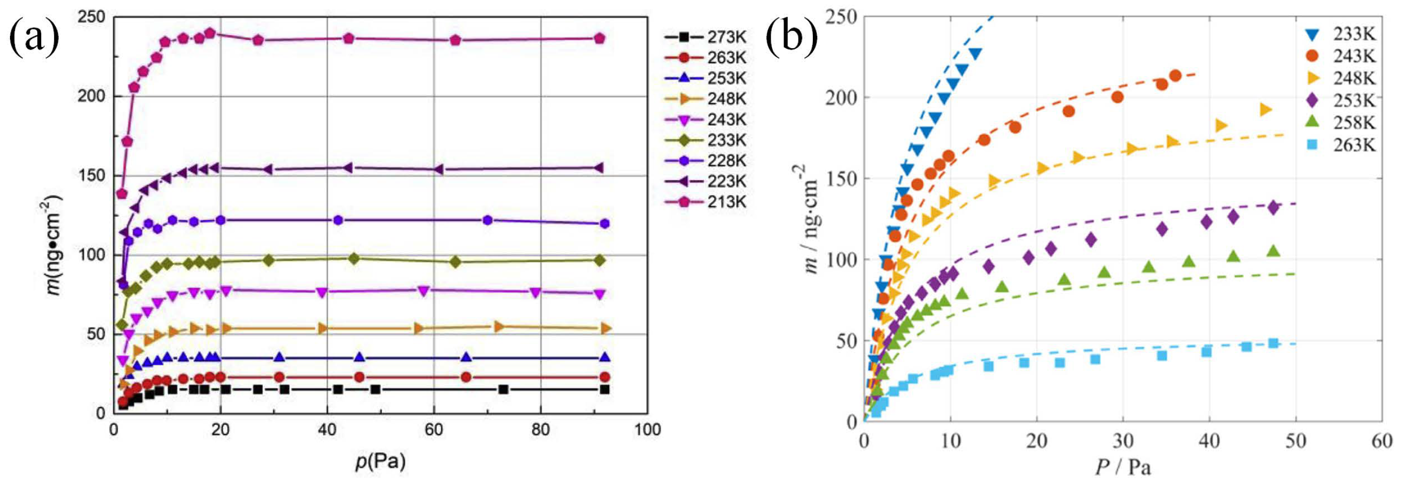
  83. Su, Y.; Cai, G.; Ling, G.; He, B.; Wu, C. Low-pressure adsorption isotherms of CO2 on low-temperature surface measured on a quartz crystal microbalance. Vacuum 2019, 168, 108851. [Google Scholar] [CrossRef]
  84. Wu, C.; He, B.; Su, Y.; Ling, G.; Cai, G. Adsorption Isotherms of Low-Pressure H2O on a Low-Temperature Surface Measured by a Quartz Crystal Microbalance. ACS Omega 2020, 5, 26673–26681. [Google Scholar] [CrossRef]
  85. Araneo, L.; Soare, V.; Payri, R.; Shakal, J. Setting up a PDPA system for measurements in a Diesel spray. J. Phys. Conf. Ser. 2006, 45, 85. [Google Scholar] [CrossRef] [Green Version]
  86. Sijs, R.; Kooij, S.; Holterman, H.; Van De Zande, J.; Bonn, D. Drop size measurement techniques for sprays: Comparison of image analysis, phase Doppler particle analysis, and laser diffraction. AIP Adv. 2021, 11, 15315. [Google Scholar] [CrossRef]
  87. McPhail, Y.M. An experimental rocket model and numerical plume boundary studies for under-expanded flow. Ph.D. Thesis, The University of New South Wales, Kensington, NSW, Australia, 2011. [Google Scholar]
  88. Fisher, S.; Bharathan, D. Glow-discharge flow visualization in low-density free jets. J. Spacecr. Rockets 1973, 10, 658–662. [Google Scholar] [CrossRef]
  89. Han, Y.; Cai, G.B.; Xu, X.; Bruno, R.; Abdelkrim, B. A conditioned level-set method with block-division strategy to flame front extraction based on OH-PLIF measurements. Chin. Phys. B 2014, 23, 58901. [Google Scholar] [CrossRef]
  90. Han, Y.; Cai, G.B.; Wang, H.X.; Bruno, R.; Abdelkrim, B. Flow characterization and dilution effects of N2 and CO2 on premixed CH4/air flames in a swirl-stabilized combustor. Chin. Phys. B 2014, 23, 34704. [Google Scholar] [CrossRef]
  91. Dai, J.; Cai, G.; Zhang, Y.; Yu, N. Experimental investigations of coaxial injectors in a laboratory-scale rocket combustor. Aerosp. Sci. Technol. 2016, 59, 41–51. [Google Scholar] [CrossRef]
  92. Dai, J.; Cai, G.; Zhang, Y.; Yu, N. Experimental and numerical investigation of combustion characteristics on GO2/GH2 shear coaxial injector. Aerosp. Sci. Technol. 2018, 77, 725–732. [Google Scholar] [CrossRef]
  93. Tang, Z.; He, B.; Cai, G. Investigation on a coupled Navier–Stokes–Direct Simulation Monte Carlo method for the simulation of plume flowfield of a conical nozzle. Int. J. Numer. Methods Fluids 2014, 76, 95–108. [Google Scholar] [CrossRef]
  94. Yang, Z.; Tang, Z.Y.; Cai, G.B.; He, B.J. Development of a coupled NS-DSMC method for the simulation of plume impingement effects of space thrusters. Thermophys. Aeromechanics 2017, 24, 835–847. [Google Scholar] [CrossRef]
  95. Cai, G.B.; Tang, Z.Y.; Wei, X.Q. Investigation on the Interface Smoothing of Coupled N–S/DSMC Method Using Image Processing Filters. Adv. Astronaut. Sci. Technol. 2018, 1, 221–227. [Google Scholar] [CrossRef] [Green Version]
  96. Bird, G. The DS2V/3V program suite for DSMC calculations. AIP Conf. Proc. 2005, 762, 541–546. [Google Scholar]
  97. Boyd, I.D. Conservative species weighting scheme for the direct simulation Monte Carlo method. J. Thermophys. Heat Transf. 1996, 10, 579–585. [Google Scholar] [CrossRef]
  98. Rader, D.; Gallis, M.; Torczynski, J.; Wagner, W. Direct simulation Monte Carlo convergence behavior of the hard-sphere-gas thermal conductivity for Fourier heat flow. Phys. Fluids 2006, 18, 77102. [Google Scholar] [CrossRef]
  99. Ren, X.; Yuan, J.; He, B.; Zhang, M.; Cai, G. Grid criteria for numerical simulation of hypersonic aerothermodynamics in transition regime. J. Fluid Mech. 2019, 881, 585–601. [Google Scholar] [CrossRef]
  100. Cai, G.; Ren, X.; He, B.; Tang, Z.; Yuan, J. The dependence of transport coefficient on spatial dimensions and grid shape in the direct simulation Monte Carlo based on Green–Kubo relation. Phys. Fluids 2020, 32, 42006. [Google Scholar]
  101. LeBeau, G.; Lumpkin Iii, F. Application highlights of the DSMC Analysis Code (DAC) software for simulating rarefied flows. Comput. Methods Appl. Mech. Eng. 2001, 191, 595–609. [Google Scholar] [CrossRef]
  102. Stewart, B.; Lumpkin, F., III. Axisymmetric Plume Simulations with NASA’s DSMC Analysis Code; Technical Report; National Aeronautics and Space Administration: Washington, DC, USA, 2012.
  103. Giordano, D.; Ivanov, M.; Kashkovsky, A.; Markelov, G.; Tumino, G.; Koppenwallner, G. Application of numerical multizone approach to the study of satellite thruster plumes. J. Spacecr. Rockets 1998, 35, 502–508. [Google Scholar] [CrossRef]
  104. Dietrich, S.; Boyd, I. A scalar optimized parallel implementation of the DSMC method. In Proceedings of the 32nd Aerospace Sciences Meeting and Exhibit, Reno, NV, USA, 10–13 January 1994; American Institute of Aeronautics and Astronautics: Reston, VA, USA, 1994. [Google Scholar]
  105. Tseng, K.C.; Hu, L.H.; Kuo, T.C.; Chen, Y.S.; Lee, U.M.; Wu, J.S. Disturbance analysis from plume impingement by using the parallel DSMC Code (PDSC). In Proceedings of the 39th AIAA Thermophysics Conference, Miami, FL, USA, 25–28 June 2007; American Institute of Aeronautics and Astronautics: Reston, VA, USA, 2007. [Google Scholar]
  106. Simpson, H.; Wallace, N.; Clark, S.; Mundy, D. A description of the new 3.8 m diameter high power electric propulsion test facility at QinetiQ, Farnborough, UK. In Proceedings of the 28th International Electric Propulsion Conference, Toulouse, France, 17–21 March 2003; Electric Rocket Propulsion Society: Gainesville, VA, USA, 2003. [Google Scholar]
  107. Scortecci, F.; Bonelli, E.; Michelozzi, B.; Saito, F.; Scaranzin, S.; Turco, A. Performance of a large vacuum facility for spacecraft propulsion testing. In Proceedings of the 4th International Spacecraft Propulsion Conference, Sardinia, Italy, 2–9 June 2004; European Space Agency: Paris, France, 2004. [Google Scholar]
  108. Saverdi, M.; Signori, M.; Milaneschi, L.; Cesari, U.; Biagioni, L. The IV10 space simulator for high power electric propulsion testing: Performance improvements and operation status. In Proceedings of the 30th International Electric Propulsion Conference, Florence, Italy, 17–20 September 2007; Electric Rocket Propulsion Society: Gainesville, VA, USA, 2007. [Google Scholar]
  109. Shang, S.; Cai, G.; Zhu, D.; He, B. Design of double-layer anti-sputtering targets for plume effects experimental system. Sci. China Technol. Sci. 2016, 59, 1265–1275. [Google Scholar] [CrossRef]
  110. Garner, C.; Polk, J.; Brophy, J.; Goodfellow, K. Methods for cryopumping xenon. In Proceedings of the 32nd Joint Propulsion Conference and Exhibit, Lake Buena Vista, FL, USA, 1–3 July 1996; American Institute of Aeronautics and Astronautics: Reston, VA, USA, 1996. [Google Scholar]
  111. Spektor, R. Analytical Pumping Speed Models for Electric Propulsion Vacuum Facilities. J. Propuls. Power 2021, 37, 391–399. [Google Scholar] [CrossRef]
  112. Brown, D.L.; Walker, M.L.; Szabo, J.; Huang, W.; Foster, J.E. Recommended practice for use of Faraday probes in electric propulsion testing. J. Propuls. Power 2017, 33, 582–613. [Google Scholar] [CrossRef] [Green Version]
  113. Bustos, A.; Juarez, A.; De Urquijo, J.; Muñoz, M. An automated Langmuir probe controller for plasma characterization. Meas. Sci. Technol. 2016, 27, 87002. [Google Scholar] [CrossRef]
  114. Oh, S.J.; Choi, I.J.; Kim, J.Y.; Chung, C.W. Double probe diagnostics based on harmonic current detection for electron temperature and electropositive ion flux measurement in RF plasmas. Meas. Sci. Technol. 2012, 23, 85001. [Google Scholar] [CrossRef]
  115. Bekkeng, T.; Jacobsen, K.; Bekkeng, J.; Pedersen, A.; Lindem, T.; Lebreton, J.; Moen, J. Design of a multi-needle Langmuir probe system. Meas. Sci. Technol. 2010, 21, 85903. [Google Scholar] [CrossRef]
  116. Lobbia, R.B.; Beal, B.E. Recommended practice for use of Langmuir probes in electric propulsion testing. J. Propuls. Power 2017, 33, 566–581. [Google Scholar] [CrossRef]
  117. Kim, S.W. Experimental Investigations of Plasma Parameters and Species-Dependent Ion Energy Distribution in the Plasma Exhaust Plume of a Hall Thruster. Ph.D. Thesis, University of Michigan, Ann Arbor, MI, USA, 1999. [Google Scholar]
  118. Shastry, R.; Hofer, R.R.; Reid, B.M.; Gallimore, A.D. Method for analyzing E× B probe spectra from Hall thruster plumes. Rev. Sci. Instrum. 2009, 80, 63502. [Google Scholar] [CrossRef] [Green Version]
  119. Farnell, C.C.; Farnell, C.C.; Farnell, S.C.; Williams, J.D. Recommended practice for use of electrostatic analyzers in electric propulsion testing. J. Propuls. Power 2017, 33, 638–658. [Google Scholar] [CrossRef]
  120. Chen, X.; He, B.; Gu, Z.; Geng, H.; Guo, N.; Zhao, Y.; Shi, K.; Tian, K.; Chen, T.; Ma, Y. Investigation into the thermal effect of the LIPS-200 ion thruster plume. Plasma Sci. Technol. 2022, 24, 74003. [Google Scholar]
  121. Weng, H.; Cai, G.; Liu, L.; Zheng, H.; Zhang, M.; Zhang, B.; He, B. Modifying the theoretical model of the target indirect measurement method for measuring the thrust of electric propulsion. Meas. Sci. Technol. 2021, 32, 85301. [Google Scholar] [CrossRef]
  122. Zhang, Z.; Zhang, Z.; Wang, Y.; Zhang, G.; Qi, J.; Liu, J.; Tang, H.; Cao, J. Simultaneous experimental verification of indirect thrust measurement method based on Hall-effect thruster and plasma plume. Vacuum 2022, 204, 111384. [Google Scholar]
  123. Shang, S.; Xiang, S.; Jiang, L.; Wang, W.; He, B.; Weng, H. Sputtering distribution of lips200 ion thruster plume. Acta Astronaut. 2019, 160, 7–14. [Google Scholar] [CrossRef]
  124. Kempkens, H.; Uhlenbusch, J. Scattering diagnostics of low-temperature plasmas (Rayleigh scattering, Thomson scattering, CARS). Plasma Sources Sci. Technol. 2000, 9, 492. [Google Scholar] [CrossRef]
  125. Zhu, X.M.; Pu, Y.K. Using OES to determine electron temperature and density in low-pressure nitrogen and argon plasmas. Plasma Sources Sci. Technol. 2008, 17, 24002. [Google Scholar] [CrossRef]
  126. Akatsuka, H. Optical Emission Spectroscopic (OES) analysis for diagnostics of electron density and temperature in non-equilibrium argon plasma based on collisional-radiative model. Adv. Phys. X 2019, 4, 1592707. [Google Scholar] [CrossRef] [Green Version]
  127. Nauschütt, B.T.; Chen, L.; Holste, K.; Klar, P.J. Non-invasive assessment of plasma parameters inside an ion thruster combining optical emission spectroscopy and principal component analysis. EPJ Tech. Instrum. 2021, 8, 13. [Google Scholar] [CrossRef]
  128. Nauschütt, B.; Chen, L.; Holste, K.; Klar, P.J. Combination of optical emission spectroscopy and multivariate data analysis techniques as a versatile non-invasive tool for characterizing xenon/krypton mixed gas plasma inside operating ion thrusters. J. Appl. Phys. 2022, 131, 53301. [Google Scholar] [CrossRef]
  129. Vincent, B.; Tsikata, S.; Mazouffre, S.; Minea, T.; Fils, J. A compact new incoherent Thomson scattering diagnostic for low-temperature plasma studies. Plasma Sources Sci. Technol. 2018, 27, 55002. [Google Scholar] [CrossRef]
  130. Yamashita, Y.; Tsukizaki, R.; Kinefuchi, K.; Koda, D.; Tani, Y.; Nishiyama, K. Neutral ground state particle density measurement of xenon plasma in microwave cathode by two-photon laser-induced fluorescence spectroscopy. Vacuum 2019, 168, 108846. [Google Scholar] [CrossRef]
  131. Liebeskind, J.G.; Hanson, R.K.; Cappelli, M.A. Laser-induced fluorescence diagnostic for temperature and velocity measurements in a hydrogen arcjet plume. Appl. Opt. 1993, 32, 6117–6127. [Google Scholar] [CrossRef]
  132. Mazouffre, S. Laser-induced fluorescence diagnostics of the cross-field discharge of Hall thrusters. Plasma Sources Sci. Technol. 2012, 22, 13001. [Google Scholar] [CrossRef]
  133. Young, C.; Fabris, A.L.; MacDonald-Tenenbaum, N.; Hargus, W.; Cappelli, M. Time-resolved laser-induced fluorescence diagnostics for electric propulsion and their application to breathing mode dynamics. Plasma Sources Sci. Technol. 2018, 27, 94004. [Google Scholar] [CrossRef] [Green Version]
  134. Han, X.; Zhang, Z.; Chen, Z.; Marano, M.; Tang, H.; Cao, J. High-spatial-resolution image reconstruction-based method for measuring electron temperature and density of the very near field of an applied-field magnetoplasmadynamic thruster. J. Phys. D Appl. Phys. 2021, 54, 135203. [Google Scholar] [CrossRef]
  135. Kim, J.; Lee, D.; Doh, G.; Park, S.; Kim, H.; Choe, W. Three-dimensional tomographically reconstructed optical emission profiles of Hall thruster plasmas. Plasma Sources Sci. Technol. 2022, 31, 15013. [Google Scholar] [CrossRef]
  136. Buneman, O. Dissipation of currents in ionized media. Phys. Rev. 1959, 115, 503. [Google Scholar] [CrossRef]
  137. Dawson, J. One-dimensional plasma model. The Phys. Fluids 1962, 5, 445–459. [Google Scholar] [CrossRef]
  138. Ferguson, D.; Gardner, B.; Kuharski, R.; Davis, V. Electric propulsion interactions code (EPIC): Recent enhancements and goals for future capabilities. In Proceedings of the 45th AIAA Aerospace Sciences Meeting and Exhibit, Reno, NV, USA, 8–11 January 2007; American Institute of Aeronautics and Astronautics: Reston, VA, USA, 2007. [Google Scholar]
  139. Roussel, J.F.; Rogier, F.; Dufour, G.; Mateo-Velez, J.C.; Forest, J.; Hilgers, A.; Rodgers, D.; Girard, L.; Payan, D. SPIS open-source code: Methods, capabilities, achievements, and prospects. IEEE Trans. Plasma Sci. 2008, 36, 2360–2368. [Google Scholar] [CrossRef]
  140. Cai, G.; Zheng, H.; Liu, L.; Ren, X.; He, B. Three-dimensional particle simulation of ion thruster plume impingement. Acta Astronaut. 2018, 151, 645–654. [Google Scholar] [CrossRef]
  141. Zheng, H.; Cai, G.; Liu, L.; Shang, S.; He, B. Three-dimensional particle simulation of back-sputtered carbon in electric propulsion test facility. Acta Astronaut. 2017, 132, 161–169. [Google Scholar] [CrossRef]
  142. Liu, L.; Cai, G.; Zheng, H.; Shang, S.; He, B. Measurement of the momentum accommodation coefficient for the interactions between electric thruster plume and a solid surface. Phys. Plasmas 2020, 27, 53511. [Google Scholar] [CrossRef]
  143. Cai, G.; Zhang, B.; He, B.; Weng, H.; Liu, L. Research on the intelligent computation of vacuum plume (in Chinese). Acta Aeronaut. Astronaut. Sin. 2022, 43, 527352. [Google Scholar]
  144. Sekar, V.; Jiang, Q.; Shu, C.; Khoo, B.C. Fast flow field prediction over airfoils using deep learning approach. Phys. Fluids 2019, 31, 57103. [Google Scholar] [CrossRef]
  145. Hui, X.; Bai, J.; Wang, H.; Zhang, Y. Fast pressure distribution prediction of airfoils using deep learning. Aerosp. Sci. Technol. 2020, 105, 105949. [Google Scholar] [CrossRef]
  146. Wang, Y.; Liu, T.; Zhang, D.; Xie, Y. Dual-convolutional neural network based aerodynamic prediction and multi-objective optimization of a compact turbine rotor. Aerosp. Sci. Technol. 2021, 116, 106869. [Google Scholar] [CrossRef]
  147. Cai, G.; Zhang, B.; Liu, L.; Weng, H.; Wang, W.; He, B. Fast vacuum plume prediction using a convolutional neural networks-based direct simulation Monte Carlo method. Aerosp. Sci. Technol. 2022, 129, 107852. [Google Scholar] [CrossRef]
  148. Trott, W.M.; Castañeda, J.N.; Torczynski, J.R.; Gallis, M.A.; Rader, D.J. An experimental assembly for precise measurement of thermal accommodation coefficients. Rev. Sci. Instrum. 2011, 82, 35120. [Google Scholar] [CrossRef] [PubMed]
  149. Shuvalov, V.A. Transfer of the momentum of gas ions to the surface of a solid. J. Appl. Mech. Tech. Phys. 1984, 25, 351–358. [Google Scholar] [CrossRef]
  150. Shuvalov, V.A. Transfer of gas-ion momentum and energy to an electrically conductive surface partially coated by a thin dielectric layer. J. Appl. Mech. Tech. Phys. 1986, 27, 478–485. [Google Scholar] [CrossRef]
  151. Corey, R.L.; Snyder, J.S.; Price, X.; Malone, S.P.; Randolph, T.M. Hall thruster plume model for spacecraft impingement torque: Development and validation. J. Spacecr. Rockets 2008, 45, 766–775. [Google Scholar] [CrossRef]
  152. Wang, S.; Thynell, S. An experimental study on the hypergolic interaction between monomethylhydrazine and nitric acid. Combust. Flame 2012, 159, 438–447. [Google Scholar] [CrossRef]
  153. Saad, M.A.; Detweiler, M.B.; Sweeney, M.A. Analysis of reaction products of nitrogen tetroxide with hydrazines under nonignition conditions. AIAA J. 1972, 10, 1073–1078. [Google Scholar] [CrossRef]
  154. Liu, C.K.; Glassford, A. Contamination effect of MMH/N2O4 rocket plume product deposit. J. Spacecr. Rockets 1981, 18, 306–311. [Google Scholar] [CrossRef]
  155. Bonn, O.d.; Hammerl, A.; Klapötke, T.M.; Mayer, P.; Piotrowski, H.; Zewen, H. Plume deposits from bipropellant rocket engines: Methylhydrazinium nitrate and N, N-dimethylhydrazinium nitrate. Z. fur Anorg. Allg. Chem. 2001, 627, 2011–2015. [Google Scholar] [CrossRef]
  156. Tsai, P.; Pacheco, S.; Pirat, C.; Lefferts, L.; Lohse, D. Drop impact upon micro-and nanostructured superhydrophobic surfaces. Langmuir 2009, 25, 12293–12298. [Google Scholar] [CrossRef] [Green Version]
  157. Tsai, P.; CA van der Veen, R.; van de Raa, M.; Lohse, D. How micropatterns and air pressure affect splashing on surfaces. Langmuir 2010, 26, 16090–16095. [Google Scholar] [CrossRef] [PubMed] [Green Version]
  158. Tsai, P.; Hendrix, M.H.; Dijkstra, R.R.; Shui, L.; Lohse, D. Microscopic structure influencing macroscopic splash at high Weber number. Soft Matter 2011, 7, 11325–11333. [Google Scholar] [CrossRef]
  159. Josserand, C.; Thoroddsen, S.T. Drop impact on a solid surface. Annu. Rev. Fluid Mech. 2016, 48, 365–391. [Google Scholar] [CrossRef] [Green Version]
  160. Liu, L.; Cai, G.; Tsai, P.A. Drop impact on heated nanostructures. Langmuir 2020, 36, 10051–10060. [Google Scholar] [CrossRef] [PubMed]
  161. Liu, L.; Zhang, Y.; Cai, G.; Tsai, P.A. High-speed dynamics and temperature variation during drop impact on a heated surface. Int. J. Heat Mass Transf. 2022, 189, 122710. [Google Scholar] [CrossRef]
  162. Land, N.S.; Clark, L.V. Experimental Investigation of Jet Impingement on Surfaces of Fine Particles in a Vacuum Environment; National Aeronautics and Space Administration: Washington, DC, USA, 1965.
  163. Land, N.S.; Scholl, H.F. Scaled Lunar Module Jet Erosion Experiments; National Aeronautics and Space Administration: Washington, DC, USA, 1969.
  164. Morris, A.B.; Goldstein, D.B.; Varghese, P.L.; Trafton, L.M. Approach for modeling rocket plume impingement and dust dispersal on the moon. J. Spacecr. Rockets 2015, 52, 362–374. [Google Scholar] [CrossRef]
  165. You, J.; Zhang, X.; Zhang, H.; Li, C.; Xu, Y.; Yan, Q.; Yu, H.; Liu, J.; Li, Y.; Wang, Y.; et al. Analysis of plume–lunar surface interaction and soil erosion during the Chang’E-4 landing process. Acta Astronaut. 2021, 185, 337–351. [Google Scholar] [CrossRef]
  166. He, X.; He, B.; Cai, G. Simulation of rocket plume and lunar dust using DSMC method. Acta Astronaut. 2012, 70, 100–111. [Google Scholar] [CrossRef]
  167. Li, Y.; Ren, D.; Bo, Z.; Huang, W.; Ye, Q.; Cui, Y. Gas-particle two-way coupled method for simulating the interaction between a rocket plume and lunar dust. Acta Astronaut. 2019, 157, 123–133. [Google Scholar] [CrossRef]
  168. Bo, Z.; Feng, Y.; Huang, W.; Cui, Y. Diffusion phenomenon of lunar soil particles under a plume in a vacuum environment by numerical simulation. Acta Astronaut. 2020, 171, 403–414. [Google Scholar] [CrossRef]
  169. Bo, Z.; Xie, Y.; Li, Y.; Yu, W.; Cui, Y. Collision phenomenon of lunar-soil particles under engine plume in a vacuum by numerical study. Acta Astronaut. 2021, 189, 615–623. [Google Scholar] [CrossRef]
  170. Zhang, H.; Li, C.; You, J.; Zhang, X.; Wang, Y.; Chen, L.; Fu, Q.; Zhang, B.; Wang, Y. The Investigation of Plume-Regolith Interaction and Dust Dispersal during Chang’E-5 Descent Stage. Aerospace 2022, 9, 358. [Google Scholar] [CrossRef]
  171. Capecelatro, J. Modeling high-speed gas–particle flows relevant to spacecraft landings. Int. J. Multiph. Flow 2022, 150, 104008. [Google Scholar] [CrossRef]
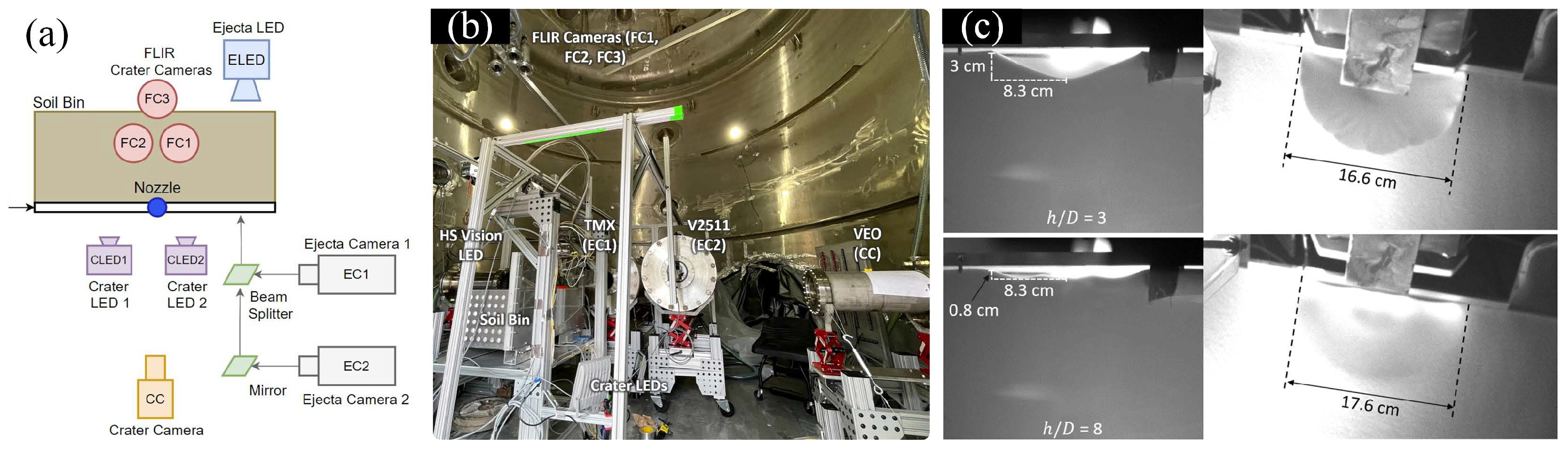
  172. Diaz-Lopez, M.X.; Gorman, M.; Rubio, J.S.; Ni, R. Plume-surface Interaction Physics Focused Ground Test 1: Diagnostics and Preliminary Results. In Proceedings of the AIAA SCITECH 2022 Forum, San Diego, CA, USA, 3–7 January 2022; American Institute of Aeronautics and Astronautics: Reston, VA, USA, 2022. [Google Scholar]
  173. Rubio, J.S.; Gorman, M.; Diaz-Lopez, M.X.; Ni, R. Plume-Surface Interaction Physics Focused Ground Test 1: Setup and Preliminary Results. In Proceedings of the AIAA SCITECH 2022 Forum, San Diego, CA, USA, 3–7 January 2022; American Institute of Aeronautics and Astronautics: Reston, VA, USA, 2022. [Google Scholar]
  174. Korzun, A.M.; Eberhart, C.J.; West, J.; Liever, P.; Weaver, A.; Mantovani, J.; Langton, A.; Kemmerer, B.; Atkins, A. Design of a Subscale, Inert Gas Test for Plume-Surface Interactions in a Reduced Pressure Environment. In Proceedings of the AIAA SCITECH 2022 Forum, San Diego, CA, USA, 3–7 January 2022; American Institute of Aeronautics and Astronautics: Reston, VA, USA, 2022. [Google Scholar]
  175. Eberhart, C.J.; West, J.; Korzun, A.M. Overview of Plume-Surface Interaction Data from Subscale Inert Gas Testing at NASA MSFC Test Stand 300 Vacuum Facilities. In Proceedings of the AIAA SCITECH 2022 Forum, San Diego, CA, USA, 3–7 January 2022; American Institute of Aeronautics and Astronautics: Reston, VA, USA, 2022. [Google Scholar]
Figure 1. Simulation results of (a) density and (b) Knudsen number of a bipropellant thruster (6 N). The results are simulated via the software of plume work station (PWS), which is self-developed by Beihang University [1]. The unit of density is kg/m 3 .
Aerospace 09 00706 g001
Figure 2. Schematic of the vacuum plume generated at the background pressure of (a) 1 Pa, (b) 2.5 × 10 3 Pa, and (c) 0 Pa, which are simulated by PWS.
Aerospace 09 00706 g002
Figure 3. Plume effect test system (PES) of Beihang University.
Aerospace 09 00706 g003
Figure 4. (a) Schematic of Pitot tube array and (b) its typical measurement results of a plume flow exhausted by a bipropellant thruster (60 N) [56].
Aerospace 09 00706 g004
Figure 5. (a) Schematic and setup of the tunable diode laser absorption spectroscopy (TDLAS). (b) Recorded plume snapshot. (c) The measured velocity by the TDLSA for different propellants [72].
Aerospace 09 00706 g005
Figure 6. (a) Representative snapshots captured by the particle image velocimetry (PIV) of the (a) conical nozzle and (b) bell nozzle fed with the cold N 2 . The corresponding calculated velocities are shown in (c,d).
Aerospace 09 00706 g006
Figure 7. (a) Schematic of the measurement of rocket engine exhaust using the hydroxyl tagging velocimetry (HTV). (b) The corresponding measurement (inset) and simulation results [78].
Aerospace 09 00706 g007
Figure 8. (a) Schematic of computation domain of decoupled and coupled methods. (b) The results of density obtained by the decoupled and coupled methods.
Aerospace 09 00706 g008
Figure 9. Simulation results of (a) pressure and (b) heat flux distribution during the Lunar probe descending [2]. Simulation results of (c) pressure and (d) heat flux loaded on the solar panels of passive vehicle during the rendezvous and docking. All the results are obtained by PWS.
Aerospace 09 00706 g009
Figure 10. (a) Snapshot (left) and schematic (right) of the double-layer anti-sputtering target. (b) Schematic of primary-end and secondary-end structures. A–A refers to the cross-section view [109].
Aerospace 09 00706 g010
Figure 11. Current density measured by the Faraday probe array for the LIPS-200 ion thruster [46]. The red line refers to the diameter of thruster exit plane.
Aerospace 09 00706 g011
Figure 12. The measured plasma potential, floating potential, and electron temperature by the Langmuir probe for the LIPS-200 ion thruster [47].
Aerospace 09 00706 g012
Figure 13. (a) Schematic of the E × B probe with an active cooling system. (b) The typical spectra measured by the E × B probe for the LIPS-200 ion thruster [49].
Aerospace 09 00706 g013
Figure 14. (a) Schematic of the retarding potential analyzer (RPA) and (b) the corresponding measured ion energy of the LIPS-200 ion thruster [48].
Aerospace 09 00706 g014
Figure 15. (a) Schematic of sputtering effect measurement for the LIPS-200 ion thruster. (b) The corresponding experimental and simulation results at different conditions [123].
Aerospace 09 00706 g015
Figure 16. (a) Computational domain of a surface immersed in the plasma plume flow of the LIPS-200 ion thruster. (b) The number density simulated by EX-PWS. (c) Force exerted on the immersed surface simulated by EX-PWS [140].
Aerospace 09 00706 g016
Figure 17. (a) Number density distribution of Xe + when two paralleled LIPS-200 ion thrusters are firing, which is simulated by EX-PWS. (b) The heated flux loaded on the solar panel. (c) The sputtered particle on the solar panel.
Aerospace 09 00706 g017
Figure 18. Data preprocessing and training processes of CNN-DSMC method [147].
Aerospace 09 00706 g018
Figure 19. (a) Network architecture for CNN-DSMC in the prediction of vacuum plume. (b) Architecture of a single convolution (deconvolution) block [147].
Aerospace 09 00706 g019
Figure 20. (a) Schematic of computational domain and boundary conditions of the two-dimensional axisymmetric case. (b) The axial (left) and radial (right) velocities at the altitude of h = 8.2 m obtained by the DSMC and CNN-DSMC [147].
Aerospace 09 00706 g020
Figure 21. (a) Schematic of computational domain of the three-dimensional case. (b) The velocities at the altitude of h = 8.2 m obtained by the DSMC and CNN-DSMC [147].
Aerospace 09 00706 g021
Figure 22. Saturation gas adsorption at the conditions of low-temperature and low pressure for (a) CO 2 [83] and (b) H 2 O [84].
Aerospace 09 00706 g022
Figure 23. Captured droplets depositing the surface after after plume–surface interactions on the (a) ground test [7] and (b) on-orbit test [11]. (c) The surface damage observed in on-orbit test [11].
Aerospace 09 00706 g023
Figure 24. Plume–Lunar Lunar/Mars regolith interaction test performed by NASA. (a) Top view schematic of the diagnostic system [173]. (b) The corresponding diagnostic system inside the vacuum chamber [172]. (c) The captured crater from the side and top views [172].
Aerospace 09 00706 g024
Figure 25. Plume–Lunar regolith interaction test conducted at Beihang University. (a) Representative snapshot captured by the particle image velocimetry (PIV). (b) The corresponding velocity of ejected particles calculated from PIV.
Aerospace 09 00706 g025
Publisher’s Note: MDPI stays neutral with regard to jurisdictional claims in published maps and institutional affiliations.

