Article

Optimal Cooperative Guidance Strategies for Aircraft Defense with Impact Angle Constraints

1
School of Astronautics, Northwestern Polytechnical University, Xi’an 710072, China
2
Unmanned System Research Institute, Northwestern Polytechnical University, Xi’an 710072, China
*
Author to whom correspondence should be addressed.
Aerospace 2022, 9(11), 710; https://doi.org/10.3390/aerospace9110710
Submission received: 11 September 2022 / Revised: 9 November 2022 / Accepted: 10 November 2022 / Published: 12 November 2022
(This article belongs to the Section Aeronautics)

Abstract

:
Given the limitations of escape maneuvers and decoy deployment of combat aircraft under missile attacks; active defense dramatically improves the survival chances by launching active defense missiles to intercept incoming missiles. Different from previous work, this paper implemented impact angle constraints on the defense missile to achieve a better defense effect. The low-cost active defense missile with limited maneuverability is considered to cooperate with the aircraft through three mechanisms, namely two-way cooperation without any predetermined strategy, one-way cooperation with the defense missile employing a linear guidance strategy, and one-way cooperation with independent evasion maneuver for the target. Three optimal cooperative guidance strategies with impact angle constraints were investigated. Finally, a nonlinear two-dimensional model for agents with first-order autopilot dynamics was simulated to verify the performance of the proposed strategies. The simulation results indicated that the cooperative mechanism directly affects the available range of impact angles, and the constraints of a big impact angle can be realized by introducing the nonlinear model parameters and considering the angle variation between the velocity vector and the initial line-of-sight. Furthermore, the two-way cooperative mechanism achieves the best performance and more flexible solutions to accommodate different vehicle maximum overload limits.

1. Introduction

In modern warfare, capturing and maintaining air supremacy has a decisive influence on the course and outcome of campaigns. In addition to improving the combat performance of fighter aircraft, it is also very important to improve survivability in combat. Nowadays, the protection technology for fighter aircraft has already been mature, but it focuses on avoiding being found, tracked, attacked. Once attacked by an enemy air-to-air missile, a protective measure is taken to perform evasive maneuvers and various decoying operations, which can be considered a passive defense measure because the objective is to make a successful escape. However, with the continuous improvement of surface-to-air and air-to-air missile maneuver and anti-interference capability, the limitations of traditional passive defense measures are increasingly exposed, and it becomes more and more difficult to meet the requirements of aircraft protection on the battlefield. Therefore, at present, all countries in the world are vigorously exploring new approaches to improve the survivability of military aircraft, among which active protection is very representative and has broad application prospects. When the target aircraft is attacked by an incoming missile, an active defense missile can be deployed to intercept from its own or other friendly forces, which is called “three-body engagement.” Instead of pursuit-evasion, an active defense missile is introduced into the engagement.
Active defense measures have been studied in recent years, and most of the research on terminal constraint focuses on the requirement of miss distance. The main research methods can be divided into the line-of-sight (LOS) guidance method, the optimal control theory, the differential game theory, the sliding mode control theory, etc.
LOS guidance for active defense is based on the classical three-point guidance, which attempts to keep the defense missile on the LOS between the target and the missile [1,2] so that the latter will be destroyed by the defense missile before the former is intercepted. Ratnoo and Shima [3] analyzed the kinematic relationship of LOS guidance. The speed and acceleration requirements were compared for the missile, and it was shown that better performance can be achieved by adopting the cooperative strategy. Kumar and Mukherjee [4] designed the LOS guidance strategy based on sliding mode control, and the same method was presented in [5]. To generalize the LOS guidance concept, Kumar and Mukherjee [6] proposed guidance strategies and pointed out that knowledge of the bound of interceptor acceleration is necessary.
On the premise of a known linear guidance strategy of the incoming missile, optimal cooperative guidance strategies can be designed by selecting different optimal performance indexes. Shaferman and Shima [7] used a nonlinear adaptation of a multiple-model adaptive estimator based on an extended Kalman filter to identify the homing-missile guidance law, and a matched defender’s missile guidance law was proposed. Fang et al. [8] proposed the static multiple model estimator based on a square-root cubature Kalman filter to identify the potential attacking missile guidance strategy and deduced the adaptive cooperative guidance laws. Prokopov and Shima [9] derived the guidance laws by using optimal control for three types of cooperation mechanisms. The results showed that two-way cooperation achieves the best performance, and one-way cooperation performs better than the independent maneuver. Weiss and Shima [10] proposed the guidance law for the pursuer in pursuit-evasion problem, which imposed an upper (lower) bound on the miss distance, while minimizing the effort. Weiss et al. [11] proposed two guidance algorithms for the target-attacker-defender scenario, which were derived under the assumption that performance is prescribed in the sense of the required maximum miss distance for pursuit and the required minimum miss distance for evasion. Fang and Cai [12] designed two different optimal cooperative guidance laws for the target and defender, which considered the miss distance as an inequality constraint. All the strategies mentioned above were derived from a linear model, and the closed-loop analytical expression was deduced. The nonlinear model can be applied to any engagement conditions [13,14], which is scarcely possible to be obtained because it needs to solve the two-point boundary value problem (TPBVP) using numerical algorithms. In [15], the optimal control strategy was derived by a nonlinear program solver.
If the premise of optimal cooperative guidance strategies cannot be satisfied, the differential game theory [16,17,18] can be applied to obtain the minimum miss distance, even if the missile adopts its optimal guidance law. Perelman and Shima [16] studied three different cooperative strategies using the linear-quadratic differential game (LQDG) theory. Considering the limits of control quantity, Rubinsky and Gutman [18] designed the bounded differential game (BDG) guidance law for the missile from the perspective of the attacker, and similar work is also represented in [19]. Garcia et al. [20] derived the optimal strategies for a differential game composed of three agents and capturing the radius for the defense missile was considered.
In a large heading errors scenario, the guidance strategies derived from a linear model may fail, and nonlinear control techniques have been used in guidance strategies design [21]. Kumar and Shima [22] used sliding-mode control (SMC) to design the cooperative nonlinear guidance strategies by calculating the zero-effort quantities as the sliding mode surfaces. Nevertheless, the strategies did not aim to optimize any cost function. Li et al. [23] further improved the performance with the nonsingular terminal sliding mode method.
In terms of terminal performance indexes, the above studies mainly aim at satisfying the miss distance constraint, which cannot meet the tactical requirements of optimal lethality. In modern-day warfare, it might be necessary to achieve certain terminal impact angles besides ensuring interception of the target to enhance effectiveness of kill performance of the interceptor. This necessity could arise from several factors, like a specific requirement on the hit angle for maximum effectiveness of the interceptor’s warhead, a special directional kill mechanism of the interceptor, seeker positioning and orientation, or effective avoidance of the target’s countermeasures [24]. To achieve the best lethality and destroy the incoming air-to-air missile to the greatest extent, the attitude of the active defense missile should be considered when it hits the target, i.e., the impact angle constraint. If the active defense missile can achieve the accuracy of hit-to-kill interception, then the head-on intercept will get more kinetic energy damage. For the case that an active defense missile is equipped with a warhead, the lethality can be greatly improved with a terminal impact angle constraint. From the point of view of detection, impact angle constraint is beneficial to the detection of incoming missiles. The radar cross-section (RCS) in the head-on direction of the incoming missile will be minimal, while the RCS in the lateral direction will be significantly increased. As a result, intercepting the incoming missile from the lateral direction by controlling the impact angle will facilitate earlier locking and steady tracking for the active defense missile equipped with an active radar seeker. Therefore, it is urgent to research the active defense guidance method with impact angle constraint, but there are few relevant research studies in the literature. To the best of our knowledge, Saurav et al. [17] made the earliest attempt at an active defense guidance method considering the attack angle constraint, and the closed-loop analytical expression for LQDG was deduced considering the dynamics of vehicles as zero-lag. However, the derivation of guidance law-based zero-lag dynamics was too idealistic. Also, the simulation did not impose necessary overload constraints and did not consider other cooperative situations. In this study, we considered that the flight vehicles have first-order dynamic characteristics, and the maximum overload value of the defense missile is set to be smaller. In addition, we deduced the derivation of the guidance laws under more cooperative mechanisms. Kumar et al. [25] proposed guidance laws based on SMC to attack different targets at a predetermined angle. From the point of view of the incoming missile, Zhang et al. [26] proposed the guidance law with a terminal angle constraint under the assumption that the control strategies of the defense missile and the target are known.
Aiming at the scenario where a group of missiles cooperatively intercept a single maneuvering high-value target from different relative impact angles, Shaferman and Shima [27] investigated cooperative guidance laws based on optimal control. Consistent with the combat scenario in [27], Shaferman and Shima [28] derived the guidance law in the LQDG framework, which enables to attack the target from different directions for the group of missiles. Based on the optimal control and differential game theory, Shaferman and Shima [29] derived two linear quadratic guidance laws with a terminal impact angle for one-on-one engagement. Again, for the one-on-one problem, Taub and Shima [30] formulated the linear guidance strategy for the missile with constraints of time-varying acceleration and terminal impact angle. Fonod and Shima [31,32] considered the scenario where several defense missiles launched by the target intercept a homing missile cooperatively. The cooperation meant imposing different relative intercept angles for the defense missile to enhance the observability of the multi-line-of-sight measuring environment.
Aiming at the known incoming attacking missile with linear proportional guidance law, this paper proposed three types of optimal-control-based active defense guidance strategies with impact angle constraint, which satisfied the minimized miss distance and the specific terminal impact angle constraints. This paper makes the following contributions. Firstly, for the incoming attacking missile with known linear proportional guidance law, the zero-effect quantities of miss distance and terminal impact angle were calculated by introducing parameters of the nonlinear model and considering the angle variation between the velocities vector and the initial LOS, which fits for the large impact angle constraint in actual combat. Secondly, two-way cooperation guidance strategies considering the terminal impact angle constraint were designed for the target and the defender by calculating zero-effort quantities, and were verified by nonlinear model simulation. The simulation results showed that the guidance strategies can achieve a broad range of terminal impact angles with a small miss distance. Thirdly, aiming at the one-way cooperation with the defense missile employing a linear guidance strategy, known to the target, to intercept the incoming missile, the one-way cooperation guidance strategy considering the terminal impact angle constraint was designed for the target by reconstructing the state equations and calculating a new state transfer matrix. Finally, for the one-way cooperation mechanism in which the target takes an arbitrary escape strategy, the one-way cooperation guidance strategy considering the terminal impact angle constraint was designed for the defender. Then, two methods for calculating zero-effect quantities and their applicable conditions were presented.
The remainder of this paper is organized as follows. Section 2 presents the nonlinear and linear target-missile-defender engagement kinematics. The design of cooperation guidance strategies for different mechanisms are presented in Section 3, Section 4 and Section 5. Section 6 presents the simulation analysis of different impact angle commands and weight coefficients for three cooperation mechanisms, followed by concluding remarks. The computation of zero-effort impact angle for two-way cooperation is derived in Appendix A.

2. Model Description

2.1. Nonlinear Engagement Kinematics

A schematic diagram for active defense engagement in X—O—Y Cartesian inertial reference frame is shown in Figure 1. In this active aircraft defense engagement with three entities, one collision triangle is in the scenario between the attacker and the target, and the other one is in the scenario between the defender and the attacker. T, D, and M represent the target, the defender, and the missile, respectively; ( x i , y i ) , i = ( T , D , M ) represent the position of the target, defender, and missile, respectively; V i , a i , γ i , i = ( T , D , M ) represent the velocity, lateral acceleration perpendicular to the velocity, and the heading angle of each entity, respectively; The subscripts M T and M D represent the missile-target (M-T) and defender-missile (D-M), respectively; r , λ , y represent the relative distance, LOS, relative separation perpendicular to the initial LOS direction λ M T 0 or λ M D 0 , respectively; γ M D = γ M + γ D is used to denote the impact angle.
Under the assumption that each agent has arbitrary-order dynamic characteristics, the relationship between acceleration and acceleration command can be represented as:
X ˙ i = A i X i + B i u i , a i = C i X i + d i u i , i = { M , T , D }
where X i is the n-dimensional internal states, and u i is the acceleration command limited to [ u i min ,   u i max ] . In this paper, to simplify the model description, the first-order dynamic characteristics of all flight vehicles are taken as an example, i.e., A i = 1 / τ i , B i = 1 / τ i , C i = 1 , and d i = 0 , where τ i is the time constant. It should be noted that the method presented in this paper is also applicable to vehicles with arbitrary order. The dynamics of heading angles are governed by
γ ˙ M = a M V M , γ ˙ T = a T V T , γ ˙ D = a D V D
According to the geometric relation in Figure 1, the nonlinear relative kinematic equations of M-T are:
r ˙ M T = V M cos ( γ M + λ M T ) V T cos ( γ T λ M T ) λ ˙ M T = ( V M sin ( γ M + λ M T ) V T sin ( γ T λ M T ) ) / r M T r ¨ M T = a M sin ( γ M + λ M T ) + a T sin ( γ T λ M T ) + r M T λ ˙ M T 2 λ ¨ M T = ( a M cos ( γ M + λ M T ) a T cos ( γ T λ M T ) 2 r ˙ M T λ ˙ M T ) / r M T
Similarly, the relative kinematic equations of D-M in active defense are:
r ˙ M D = V M cos ( γ M + λ M D ) V D cos ( γ D λ M D ) λ ˙ M D = ( V M sin ( γ M + λ M D ) V D sin ( γ D λ M D ) ) / r M D r ¨ M D = a M sin ( γ M + λ M D ) + a D sin ( γ D λ M D ) + r M D λ ˙ M D 2 λ ¨ M D = ( a M cos ( γ M + λ M D ) a D cos ( γ D λ M D ) 2 r ˙ M D λ ˙ M D ) / r M D γ ˙ M D = a M / V M + a D / V D

2.2. Linear Engagement Kinematics

Assume that the LOS angle of initial collision triangle is small, and both D-M and M-T engagement take place near the initial triangular collision area; that is, the LOS angle has a small value and variation range. Without loss of generality, the initial LOS of D-M engagement is taken as the X-axis, and the Y-axis is perpendicular to the X-axis. Based on this small-angle assumption, the kinematic model of active defense can be linearized along the initial LOS. a i N , i = ( T , D , M ) represents the acceleration components of each flight vehicle along the Y-axis, and a i N = a i cos γ i . Let δ i = cos γ i . The guidance laws in this paper will be derived based on linearized models.
Take the state variable x = [ x M T T , x M D T ] , where x M T = [ y M T , y ˙ M T , X M , X T ] T , x M D = [ y M D , y ˙ M D , X D , γ M D ] T . The equations of motions (EOMs) of active defense considering the impact angle constraint are given as:
x ˙ = A ( t ) x + B u T u D +   C u M
where the expression of each matrix is:
A = A MT 0 4 × 4 A 21 A MD , B = B M T B M D , C = C M T C M D
and
A M T = 0 1 0 0 0 0 C M C T 0 0 A M 0 0 0 0 A T , A M D = 0 1 0 0 0 0 C D 0 0 0 A D 0 0 0 1 V D 0 , A 21 = 0 0 0 0 0 0 C M 0 0 0 0 0 0 0 1 V M 0
B M T = 0 d T 0 B T 0 4 × 1 , B M D = 0 4 × 1 0 d D B D 0 ,   C M T = 0 d M B M 0 ,   C M D = 0 d M 0 0

2.3. Timeline

Under the small-angle assumption, the time-to-go t g o M D and t g o M T of D-M and M-T can be estimated as:
t g o M D = r M D V M cos ( γ M + λ M D ) + V D cos ( γ D λ M D ) t g o M T = r M T V M cos ( γ M + λ M T ) + V T cos ( γ T λ M T )
The duration of D-M and M-T engagement is denoted as t f M D and t f M T , respectively. In a successful active defense, t f M D < t f M T needs to be satisfied, i.e., Δ t = t f M T t f M D > 0 . To make a simplification, the simulation time is set as that for the successful defender interception. In the following expressions, t f and t g o are used to represent t f M D and t g o M D , respectively.

2.4. Missile Guidance Law

Typical intercepting missile guidance laws including proportional guidance (PN), augmented proportional guidance (APN), and optimal guidance law (OGL) can be expressed as a function of the navigation coefficient, zero-effort miss distance, and time-to-go [33]. After arrangement, they can be represented as follows:
u M N = K M T ( t g o M T ) x M T + K u T ( t g o M T ) u T N
where K M T ( t g o M T ) = K 1 K 2 K M K T , which can be referred to [22]. In this paper, the premise of all guidance law derivations is that the interceptor missile guided by a linear guidance strategy form of Equation (10) has been identified.

3. Two-Way Cooperation Guidance Strategies with Impact Angle Constraints

In the two-way communication mechanism, the target and the defender are considered as a whole to complete the task, i.e., intercept the missile with a specific terminal impact angle. Each side knows the current state of the other side and knows the escape or pursuit strategy that the other side is using afterward. In this section, such an optimal two-way cooperation guidance strategy with impact angle constraints is designed for the defender and the target. Meanwhile, the control effort is introduced into the optimizing index. The target (such as an unmanned aerial vehicle) will implement a maneuvering strategy to support the defender, and the latter will fly toward the predicted collision position from the desired direction.

3.1. Two-Way Cooperation Dynamics with Impact Angle Constraints

By substituting the linear guidance law of the missile in Equation (10) to Equation (5), the EOM of the two-way cooperation is given as:
x ˙ = A Φ t g o M T x + B Φ T t g o M T u T + B Φ D u D
where A Φ t g o M T = A Φ M T t g o M T [ 0 ] 4 × 4 A Φ 21 t g o M T A M D , A Φ M T t g o M T = 0 1 0 0 d M K 1 d M K 2 C M + d M K M δ M C T d M K T δ T B M K 1 / δ M B M K 2 / δ M A M + B M K M B M K T δ T / δ M 0 0 0 A T , A Φ 21 t g o M T = 0 0 0 0 d M K 1 d M K 2 C M + d M K M δ M d M K T δ T 0 0 0 0 0 0 1 V M 0 , B Φ T t g o M T = B M T + C M T K u T C M D K u T , B Φ D = 0 4 × 1 B M D . The other matrices are given in Equations (7) and (8).

3.2. Problem Statement with Impact Angle Constraints for Two-Way Cooperation

To minimize the miss distance and reach the set impact angle for the defender are the requirements of the terminal indicator. Besides, minimum control effort during the M-D engagement is also considered. Therefore, the optimal two-way cooperation problem with terminal impact angle constraint is represented as the minimization of the following objective function:
J = 1 2 α y M D 2 t f + 1 2 α γ γ M D ( t f ) γ c M D 2 + 1 2 0 t f u D 2 ( t ) + β T u T 2 ( t ) d t
subject to Equation (11), and with α , α γ , β T being nonnegative weights. γ c M D is the set terminal impact angle command.

3.3. Order Reduction

Terminal projection [34] is adopted in this paper by proposing two new variables: zero-effort miss distance (ZMD) and zero-effort impact angle (ZIA), which will reduce the problem’s order and the calculation difficulty. In D-M engagement, the physical meaning of ZMD and ZIA is the terminal miss distance and the terminal impact angle of the defender if, from the current moment t, the defender and target do not take any maneuvers and the missile still uses the previous guidance law to chase the target aircraft. As shown in Equation (13), through terminal projection, the terminal miss distance and the terminal impact angle can be respectively denoted as Z T D and Z γ T D , where the subscript TD refers to the flight vehicle taking no maneuvers. In this paper, when the zero-effort quantities are calculated at time t, it is assumed γ i ( i = T , D , M ) remains constant after this moment.
Z T D ( t ) = D Φ ( t f , t ) x ( t ) ,   Z γ T D ( t ) = D γ Φ ( t f , t ) x ( t )
where D = 0 1 × 4 1 0 1 × 3 , D γ = 0 1 × 7 1 , and Φ ( t f , t ) is the state transition matrix [9].
The EOMs of ZMD and ZIA are obtained as Z ˙ M D and Z ˙ γ M D by differentiating with respect to time, and they can be calculated as:
Z ˙ T D = B ˜ M T t f , t u T + B ˜ M D t f , t u D Z ˙ γ T D = B ˜ γ M T t f , t u T + B ˜ γ M D t f , t u D
where B ˜ M T t f , t = D Φ B Φ T , B ˜ M D t f , t = D Φ B Φ D , B ˜ γ M T t f , t = D γ Φ B Φ T , and B ˜ γ M D t f , t = D γ Φ B Φ D .
Because Z T D ( t f ) = y T D ( t f ) and Z γ T D ( t f ) = γ T D ( t f ) , the objective function in Equation (13) can be transformed into minimizing the following cost function subject to the EOM of Equation (14):
J = 1 2 α Z T D 2 t f + 1 2 α γ Z γ T D ( t f ) γ c M D 2 + 1 2 0 t f u D 2 ( t ) + β T u T 2 ( t ) d t

3.4. Optimal Solution

The Hamiltonian for Equation (15) is obtained as
H = 1 2 u D 2 ( t ) + 1 2 β T u T 2 ( t ) + λ T D Z ˙ T D + λ γ T D Z ˙ γ T D
The adjoint equations and transversality conditions are as follows.
λ ˙ T D = H Z T D = 0 λ T D t f = α Z T D t f
λ ˙ γ T D = H Z γ T D = 0 λ γ T D t f = α γ Z γ T D ( t f ) γ c M D
The solutions to the adjoint equations of Equations (17) and (18) are immediate:
λ T D t = α Z T D t f , λ γ T D t = α γ Z γ T D ( t f ) γ c M D
The optimal two-way cooperation strategies of the defender and the target should meet the following condition.
u T = arg u T min H ,   u D = arg u D min H
By differentiating Equation (16) with respect to u T ,   u D , the open-loop optimal strategies are calculated by solving Equation (22) and using the Lagrange multiplier λ T D t and λ γ T D t from Equation (19):
H u T = β T u T + λ T D B ˜ M T + λ γ T D B ˜ γ M T = 0 H u D = u D + λ T D B ˜ M D + λ γ T D B ˜ γ M D = 0
Finally, we have
u T * = α β T Z T D t f B ˜ M T α γ β T Z γ T D ( t f ) γ c M D B ˜ γ M T u D * = α Z T D t f B ˜ M D α γ Z γ T D ( t f ) γ c M D B ˜ γ M D

3.5. Solution of the Terminal Miss Distance and Terminal Impact Angle

Now, the problem is transformed into the solution of the terminal miss distance Z T D t f and impact angle Z γ T D t f while the optimal strategies u T * and u D * are subsequently implemented. Z T D ( t ) can be represented as [22]:
Z T D ( t ) = V λ M D t g o V λ M T ϕ 52 + ϕ ^ 5 T a T N + ϕ ^ 5 M a M N τ D 2 ψ ( t g o / τ D ) a D N
where V λ M T = r M T λ ˙ M T ,   V λ M D = r M D λ ˙ M D , and Z γ T D can be calculated as
Z γ T D ( t ) = r M T λ ˙ M T ϕ 82 + ϕ ^ 8 M a M + ϕ ^ 8 T a T N τ D V D ξ t g o / τ D a D + γ M + γ D
where ϕ ^ 5 T = ϕ 5 T / δ T , ϕ ^ 5 M = ϕ 5 M / δ M ,   ψ ( μ ) = e μ + μ 1 > 0   μ > 0 ,   ξ ( μ ) = e μ 1 > 0   μ > 0 . The detailed derivations of ZIA and the coefficients ϕ ( · ) in Equation (24) are provided in Appendix A. The coefficients ϕ ^ ( · ) are only related to t g o , which are independent of δ i and can be calculated separately. The benefit of this approach is that V λ M D and V λ M T can be obtained directly for most vehicles, and satisfactory performance can be achieved by the derived guidance strategies in the large-heading-error engagement scenario [22]. According to the EOMs of Z T D t and Z γ T D t in Equation (14), we have:
Z T D t f = Z T D t + t t f B ˜ M T u T * + B ˜ M D u D * d τ   Z γ T D t f = Z γ T D t + t t f B ˜ γ M T u T * + B ˜ γ M D u D * d τ
where B ˜ M T = D Φ B Φ T = ϕ ^ 5 T δ T / τ T , B ˜ M D = D Φ B Φ D = τ D 2 δ D / τ D ψ ( t g o / τ D ) , B ˜ γ M T = D γ Φ B Φ T = ϕ ^ 8 T δ T / τ T , and B ˜ γ M D = D γ Φ B Φ D = ξ t g o / τ D / V D . Substituting the optimal guidance law of Equation (22) derived previously into Equation (25) yields:
Z T D t f = Z T D t + Q 11 Z T D t f + Q 12 Z γ T D ( t f ) γ c M D
Z γ T D ( t f ) γ c T D = Z γ T D t γ c M D + Q 21 Z TD t f + Q 22 Z γ T D ( t f ) γ c M D
where Q 11 t = α t t f B ˜ M T 2 / β T + B ˜ M D 2 d τ , Q 12 t = α γ t t f B ˜ M T B ˜ γ M T / β T + B ˜ M D B ˜ γ M D d τ , Q 21 t = α t t f B ˜ M T B ˜ M T / β T + B ˜ M D B ˜ γ M D d τ . After the transformation and reconstruction of Equations (26) and (27), Z T D t f and Z γ T D t f γ c M D can be written as
Z T D t f Z γ T D t f γ c M D = P Z T D t Z γ T D t γ c T D
where P t = P 11 t P 12 t P 21 t P 22 t = 1 1 Q 11 1 Q 22 Q 12 Q 21 1 Q 22 Q 12 Q 21 1 Q 11 . By substituting Z T D t f and Z γ T D t f γ c M D from Equation (28) back into Equation (22), u T * , u D * can be rewritten as a navigation gains form:
u T ( t ) = N T ( t ) Z T D ( t ) t go 2 + N γ T ( t ) Z γ T D t γ c M D t go 2 u D ( t ) = N D ( t ) Z T D ( t ) t go 2 + N γ D ( t ) Z γ T D t γ c M D t go 2
with the navigation gains N T ( t ) = α B ˜ M T P 11 + α γ B ˜ γ M T P 21 t go 2 / β T , N γ T ( t ) = α B ˜ M T P 12 + α γ B ˜ γ M T P 22 t go 2 / β T , N D ( t ) = α B ˜ M D P 11 + α γ B ˜ γ M D P 21 t go 2 , and N γ D ( t ) = α B ˜ M D P 12 + α γ B ˜ γ M D P 22 t go 2 .

3.6. Special Cases

Since the primary task of the defender is to destroy the target, it doesn’t make sense to constrain the impact angle without firstly obtaining the required miss distance to destroy the target. As a result, the special cases considered in this paper are listed in Table 1. When α tends to infinity, the situation corresponds to the linear-quadratic optimal cooperation strategies discussed in [9].

4. One-Way Cooperation Guidance Strategy with Impact Angle Constraints for Independent Defender

Additional hardware needs to be equipped on the defender for the communication of two-way cooperation in the previous section. A one-way cooperation mechanism is considered in this section, where the future maneuver strategy of the defender is known to the target. Then, the target can predict the behavior of the defender, and the one-way cooperative strategy is derived for the target to assist the defender to intercept the missile with a specific impact angle.

4.1. One-Way Cooperation Dynamics with Impact Angle Constraints for Independent Defender

The linear guidance law of the defender can be expressed as:
u D = L t g o x M D T   x M T T + L u M t g o u M
where L t g o = L 1   L 2   L M   L T . By substituting the guidance laws of the missile and defender into Equation (5), the EOM of the cooperative one-way cooperation for the independent defender is written as:
x ˙ = A θ t go , t g o M T x + B θ T t go , t g o M T u T
where
A θ t go , t g o M T = A θ M T t g o , t g o M T [ 0 ] A θ 21 t g o , t g o M T A θ M D
and A θ M T t g o , t g o M T = A Φ M T t g o , t g o M T , A θ 21 t go , t g o M T = 0 0 [ 0 ] [ 0 ] F K 1 F K 2 C M + F K M d D L T F K T J K 1 J K 2 J K M + B D L T J K T , F = d M L u M d D ,     J = L u M B D , A θ M D t g o = 0 1 0 d D L 1 d D L 2 C D + d D L M B D L 1 B D L 2 A D + B D L M , B θ T t g o , t g o M T = B θ M T t g o , t g o M T B θ M D t g o , B θ M T = 0 d T K u T d M B M K u T B T , B θ M D = 0 d D K u T L u M + d M K u T B D K u T L u M .

4.2. One-Way Problem Statement with Impact Angle Constraints for Independent Defender

Only considering the control effort of the target and referring to Equation (15), the optimal one-way cooperation problem with impact angle constraint is represented as minimizing the following function:
J = 1 2 α y M D 2 t f + 1 2 α γ γ M D ( t f ) γ c M D 2 + 1 2 0 t f β T u T 2 ( t ) d t
subject to the EOM of Equation (31).

4.3. Order Reduction

Different from the computational process of zero-effort quantities for two-way cooperation, the defender uses known linear guidance law to intercept the missile, then the zero-effort quantities can be denoted as Z T and Z γ T through terminal projection [35], where the subscript T refers to the target taking no maneuvers, as shown in Equation (34).
Z T ( t ) = D θ ( t f , t ) x ( t ) ,   Z γ T ( t ) = D γ θ ( t f , t ) x ( t )
where θ ( t f , t ) refers to the state transition matrix, as shown in Equation (36).
θ ( t f , t ) = θ ( t g o )   , θ ˙ ( t f , t ) = θ ( t f , t ) A θ ( t ) , θ ( t f , t f ) = I 8 × 8
By differentiation with respect to time, the EOMs of ZMD and ZIA are obtained as Z ˙ T and Z ˙ γ T :
Z ˙ T = B ˜ M T t f M D , t u T ,   Z ˙ γ T = B ˜ γ M T t f M D , t u T
where B ˜ M T t f , t = D θ t f , t B θ T , B ˜ γ M T t f , t = D γ θ t f , t B θ T . The problem can be rewritten by using Z T and Z γ T . Because Z T ( t f ) = y M D ( t f ) and Z γ T ( t f ) = γ M D ( t f ) , the objective function in Equation (33) can be transformed into minimizing the following cost function subject to the EOM of Equation (36):
J = 1 2 α Z T 2 t f + 1 2 α γ Z γ T ( t f ) γ c M D 2 + 1 2 0 t f β T u T 2 ( t ) d t

4.4. Optimal Solution

The Hamiltonian for Equation (37) is obtained as
H = 1 2 β T u T 2 ( t ) + λ T Z ˙ T + λ γ T Z ˙ γ T
The adjoint equations and transversality conditions are as follows.
λ ˙ T = H Z T = 0 λ T t f = α Z T t f
λ ˙ γ T = H Z γ T = 0 λ γ T t f = α γ Z γ T ( t f ) γ c M D
The solutions to the adjoint equations of Equations (39) and (40) are immediate:
λ T t = α Z T t f ,   λ γ T t = α γ Z γ T ( t f ) γ c M D
The optimal strategy of the target minimizes the Hamiltonian of Equation (38), and we have
u T = arg u T min H
By differentiating Equation (42) with respect to u T , the open-loop optimal strategy is calculated by solving
H u T = β T u T + λ T B ˜ M T + λ γ T B ˜ γ M T = 0
and using the Lagrange multiplier λ T t and λ γ T t from Equation (41):
u T * = α β T Z T t f B ˜ M T α γ β T Z γ T ( t f ) γ c M D B ˜ γ M T

4.5. Solution of the Terminal Miss Distance and Terminal Impact Angle

Z T can be represented as:
Z T ( t ) = V λ M T θ 52 + V λ M D θ 56 + θ ^ 5 T a T N + θ ^ 5 M a M N + θ ^ 5 D a D N
and Z γ T can be calculated as:
Z γ T ( t ) = V λ M T θ 82 + V λ M D θ 86 + θ ^ 8 M a M N + θ ^ 8 T a T N + θ 8 D a D + γ M + γ D
where θ i 2 = θ i 1 t g o M T , θ i 6 = θ i 5 t g o , θ ^ i j = θ i j / δ j , i = 5 , 8 ; j = M , T , and θ ^ 5 D = θ 5 D / δ D . The detailed derivations of zero-effort quantities and the computation of coefficients θ ( · ) in Equations (45) and (46) are calculated by referring to Appendix A. Note that the coefficients in Equations (45) and (46) are all only related to t g o and t g o M T , which can be obtained by numerical integration because the analytical expression cannot be solved. According to the EOMs of Z T t and Z γ T t in Equation (36), we have:
Z T t f = Z T t + t t f B ˜ M T u T * d τ ,   Z γ T t f = Z γ T t + t t f B ˜ γ M T u T * d τ
Substitute the optimal guidance law of Equation (44) derived previously into (47) yields:
Z T t f = Z T t + R 11 Z T t f + R 12 Z γ T ( t f ) γ c M D
Z γ T ( t f ) γ c M D = Z γ T ( t ) γ c M D + R 21 Z T t f + R 22 Z γ T ( t f ) γ c M D
where R 11 = α t t f B ˜ 1 T 2 / β T d τ , R 12 = α γ t t f B ˜ 1 T B ˜ 2 T / β T d τ , R 21 = α t t f B ˜ 1 T B ˜ 2 T / β T d τ , and R 22 = α γ t t f B ˜ 2 T 2 / β T d τ . After the transformation and reconstruction of Equations (48) and (49), Z T t f and Z γ T t f γ c M D can be written as
Z T t f Z γ T t f γ c M D = S Z T t Z γ T t γ c M D
where S t = S 11 t S 12 t S 21 t S 22 t = 1 1 R 11 1 R 22 R 12 R 21 1 R 22 R 12 R 21 1 R 11 . Finally, the optimal one-way cooperation strategy for the target is obtained by substituting Z T t f and Z γ T t f γ c M D from Equation (50) back into Equation (44), and it is rewritten with a navigation gain form:
u T ( t ) = N T ( t ) Z M D ( t ) t go 2 + N γ T ( t ) Z γ M D t γ c M D t go 2
where the navigation gains N T ( t ) = α B ˜ M T S 11 + α γ B ˜ γ M T S 21 t go 2 / β T , N γ T ( t ) = α B ˜ M T S 12 + α γ B ˜ γ M T S 22 t go 2 / β T . For the same reason as two-way cooperation, the special case to be considered here is α tends to infinity, and the navigation gains are given by:
N T ( t ) = α B ˜ M T S 11 t go 2 / β T ,   N γ T ( t ) = 0

5. One-Way Cooperation Guidance Strategy with Impact Angle Constraints for Independent Target

Here, this study focuses on the last one-way cooperation mechanism. In this mechanism, the target may perform any arbitrary maneuver, which has been known to the defender. Based on the information about the target and the missile, the defender can predict the missile’s behavior and head toward the interception point from a specific direction. If the maneuver overload value of the target is small, e.g., the constant maneuver of a small overload adopted for simulation in [9], the linear model similar to the previous one can be used to calculate, which is considered the first method here. However, if the maneuver overload value of the target is large, the linear model is no longer applicable because the angle between the speed vector and the linearized benchmark (i.e., the initial LOS angle) changes greatly. However, considering that the maneuver strategy of the target and the pursuit strategy of the missile are both known, the nonlinear simulation model can be pre-run once. Meanwhile, the precise state of the missile at any time can be obtained by directly looking up the table in the simulation for each step, and the state of the defender can be deduced through the linear model, which is considered the second method here. As for the calculation amount, the first method mainly includes the calculation of the transfer matrix, and the integral calculation in every step; the second method mainly handles the simulation process of the missile chasing the target for one time. The two methods have a similar calculation in the early stage, but the calculation amount of the second method is small in each step. Both methods will be described later.

5.1. One-Way Cooperation Dynamics with Independent Target

The linear model is used for the target maneuver with a small overload value. The EOM of the one-way cooperation with an independent target is obtained as:
x ˙ = A Φ t g o + Δ t x + B Φ T t g o + Δ t u T + B Φ D u D
where u T represents the arbitrary maneuver of the target. When the target adopts an arbitrary maneuver mode, especially a large maneuver overload, the missile state obtained through nonlinear simulation is denoted as x M ( t ) = [ y M y ˙ M a M N γ M ] . The state of the defender is x D ( t ) = [ y D y ˙ D a D N γ D ] . Then, the EOM of the defender can be expressed as:
x ˙ D = A Λ x D + B Λ D u D
where A Λ = 0 1 0 0 0 0 1 0 0 0 A D 0 0 0 1 V D δ D 0 , and B Λ D = 0 0 B D 0 T .

5.2. One-Way Problem Statement with Independent Target

Only the control effort of the defender can be considered, and by referring to Equation (15), the optimal one-way cooperation problem with impact angle constraint is represented as minimizing the following function subject to the EOM of Equation (53) or (54):
J = 1 2 α y M D 2 t f + 1 2 α γ γ M D ( t f ) γ c M D 2 + 1 2 0 t f u D 2 ( t ) d t

5.3. Order Reduction

Different from the computation process of zero-effort quantities for two-way cooperation, the target adopts its evasion maneuver. Thus, through terminal projection [34], the zero-effort quantities can be denoted as Z D and Z γ D , where the subscript D refers to the defender taking no maneuvers. For the target maneuver with a small overload value, zero-effort quantities are calculated in Equation (56).
Z D ( t ) = D Φ ( t f , t ) x ( t ) + t t f D Φ ( t f , t ) u T ( t ) d t Z γ D ( t ) = D γ Φ ( t f , t ) x ( t ) + t t f D γ Φ ( t f , t ) u T ( t ) d t
The general form of Φ ( t f , t ) has been calculated before. By differentiation with respect to time, the EOMs of ZMD and ZIA are obtained as Z ˙ D and Z ˙ γ D :
Z ˙ D = B ˜ M D t f , t u D Z ˙ γ D = B ˜ γ M D t f , t u D
where B ˜ M D t f , t = D Φ t f , t B Φ D , B ˜ γ M D t f , t = D γ Φ t f , t B Φ D . As for the target adopting any maneuver mode, the zero-effort quantities are calculated as follows:
Z D ( t ) = y M ( t f ) y D Z ( t ) Z γ D ( t ) = γ M ( t f ) + γ D Z ( t )
where y M ( t f ) and γ M ( t f ) are respectively the separation perpendicular to the initial LOS direction and the flight-path angle of the missile at t f obtained by nonlinear pre-run simulation. y D Z ( t ) and γ D Z ( t ) are respectively the zero-effort separation and flight-path angle of the defender by calculating the transfer matrix of Equation (60) when the defender takes no maneuver. The projection principle and other methods can be used to obtain the following equation:
y D Z ( t ) = y D + V D δ D t g o + τ D 2 ψ ( t g o / τ D ) a D N γ D Z ( t ) = γ D τ D ξ ( t g o / τ D ) V D a D
The EOMs of ZMD and ZIA of the second method are the same as those of the first method, which can be calculated as Equation (57). The problem can be rewritten by using Z D and Z γ D . Because Z D ( t f ) = y M D ( t f ) and Z γ D ( t f ) = γ M D ( t f ) , the objective function in Equation (55) can be transformed into minimizing the following cost function:
J = 1 2 α Z D 2 t f + 1 2 α γ Z γ D ( t f ) γ c M D 2 + 1 2 0 t f u D 2 ( t ) d t

5.4. Optimal Solution

The Hamiltonian for Equation (60) is obtained as
H = 1 2 u D 2 ( t ) + λ D Z ˙ D + λ γ D Z ˙ γ D
The adjoint equations and transversality conditions are as follows.
λ ˙ D = H Z D = 0 λ D t f = α Z D t f
λ ˙ γ D = H Z γ D = 0 λ γ D t f = α γ Z γ D ( t f ) γ c M D
The solution to the adjoint equations can be solved as:
λ D t = α Z D t f ,   λ γ D t = α γ Z γ D ( t f ) γ c M D
The optimal strategy of the target minimizes the Hamiltonian of Equation (61), and we have
u D = arg u D min H
By differentiating Equation (61) with respect to u D , the open-loop optimal strategy is calculated by solving
H u D = u D + λ D B ˜ M D + λ γ D B ˜ γ M D = 0
and using the Lagrange multiplier λ D t and λ γ D t from Equation (64). Finally, we have
u D * = α Z D t f B ˜ M D α γ Z γ D ( t f ) γ c M D B ˜ γ M D

5.5. Solution of the Terminal Miss Distance and Terminal Impact Angle

According to the EOMs of Z D t and Z γ D t in Equation (57), we have:
Z D t f = Z D t + t t f B ˜ M D u D * d τ   Z γ D t f = Z γ D t + t t f B ˜ γ M D u D * d τ
Substituting the previously derived optimal guidance law of Equation (67) into (68) yields
Z D t f = Z D t + T 11 Z D t f + T 12 Z γ D ( t f ) γ c M D Z γ D ( t f ) γ c M D = Z γ D ( t ) γ c M D + T 21 Z D t f + T 22 Z γ D ( t f ) γ c M D
where T 11 = α t t f B ˜ M D 2 d τ , T 12 = α γ t t f B ˜ M D B ˜ γ M D d τ , T 21 = α t t f B ˜ M D B ˜ γ M D d τ , and T 22 = α γ t t f B ˜ γ M D 2 d τ . After the transformation and reconstruction of Equation (69), Z D t f and Z γ D t f γ c M D can be written as
Z D t f Z γ D t f γ c M D = W Z D t Z γ D t γ c M D
where W t = W 11 t W 12 t W 21 t W 22 t = 1 1 T 11 1 T 22 T 12 T 21 1 T 22 T 12 T 21 1 T 11 . Finally, the optimal one-way cooperation strategy for the target is obtained by substituting Z T t f and Z γ T t f γ c M D of Equation (70) back into Equation (67), and it can be rewritten into the following navigation gain form:
u D ( t ) = N D ( t ) Z D ( t ) t g o 2 + N γ D ( t ) Z γ D t γ c M D t g o 2
where the navigation gains N D ( t ) = α B ˜ M D W 11 + α γ B ˜ γ M D W 21 t g o 2 , N γ D ( t ) = α B ˜ M D W 12 + α γ B ˜ γ M D W 22 t g o 2 . When α tends to infinity, the navigation gains are represented by:
N D ( t ) = α B ˜ M D V 11 t g o 2 ,   N γ D ( t ) = α B ˜ M D V 12 t g o 2

6. Simulation Analysis

The simulation analysis of the guidance law under the impact angle constraint is carried out. As mentioned above, the missile adopts the general linear guidance law, and the value of the guidance coefficient is set to 3. The other general simulation conditions are listed in Table 2, where the low-cost defender has limited maneuverability. In the simulation, all the vehicles are modelled by nonlinear kinematics equations.

6.1. Two-Way Cooperation

6.1.1. Transfer Matrix

Some of the transfer matrix elements with respect to t g o are calculated numerically using Equations (A4), (A7) and (A8), and the results are shown in Figure 2. The other necessary elements are ϕ 58 ( t g o ) = ϕ 85 ( t g o ) = ϕ 86 ( t g o ) = 0 ,     ϕ 55 ( t g o ) =   ϕ 88 ( t g o ) =   1 ,   and   ϕ 56 ( t g o ) = t g o . It can be seen from Figure 2 that the magnitude order of elements in the right column are much lower than the ones in the left column.

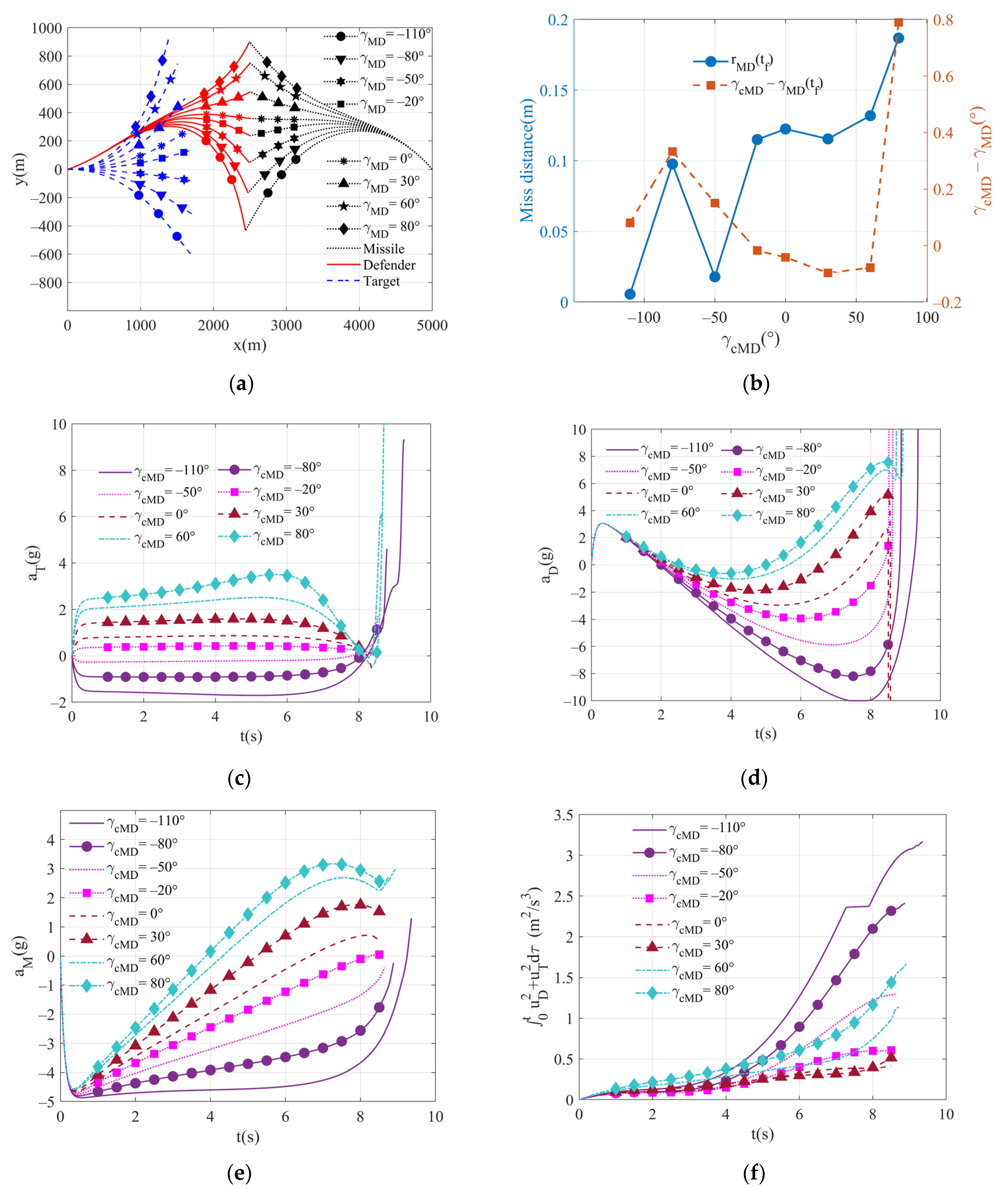
6.1.2. Simulation of Different Terminal Impact Angle Commands

The terminal impact angle commands are successively given as 110 ,   80 ,   50 ,   20 ,   0 ,   30 ,   60 ,   80 , and the weight coefficients α ,   α γ ,   β T are set to 50,000, 10 11 , 8, respectively. Figure 3a shows the trajectory diagram of the two-way cooperation guidance law, and the corresponding miss distance and actual terminal impact angle of each terminal impact angle command are illustrated in Figure 3b. It can be seen that the miss distance is less than 0.3 m when the terminal impact angle commands are within [−110 , 80 ], and it can realize hit-to-kill interception [35]. If the angle error instruction exceeds this interval, the miss distance will increase. Except for the error in the large impact angle instruction, the angle error is very small in the wide range of distribution, but it is still within the allowable range. The overload curves of the entities and total control effort are shown in Figure 3c–f, respectively. It can be seen that as γ c M D increases, the maximum overload demand of the three entities and the control effort all increase. Meanwhile, the maximum overload value of the target appears in the early stage of the engagement, while that of the defender appears in the late stage of the confrontation. For the sake of simplification, the same weight parameters are adopted under different impact angle directives, and good terminal requirements are achieved. Also, better performance can be achieved by adjusting the weight parameters.

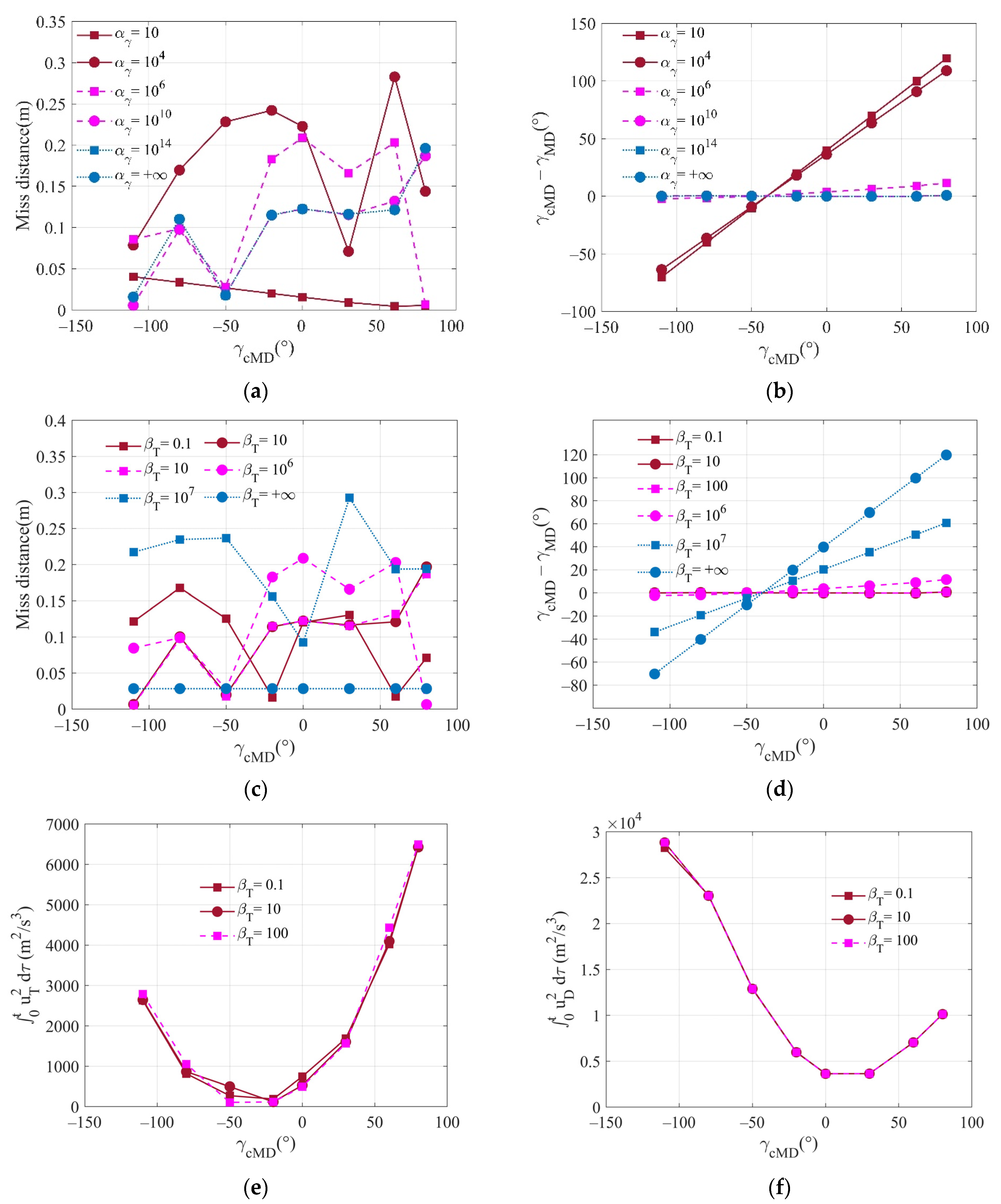
6.1.3. Variation Curves for Different Weight Coefficients

When α approaches infinity, only the minimization for miss distance is considered, which has been analyzed in [9]. The influence of different β T is mainly considered here. Here, the values of α and   α γ are the same as those in the previous subsection. Figure 4a,b show the miss distances and the terminal impact angles under different conditions, where β T is set to 0.1, 5, 8, 12, 20, and 50, respectively. It can be seen that if the terminal impact angle command is not too large, terminal quantities can meet the requirements in most cases. However, when the absolute value of the impact angle command is too large, it cannot be satisfied if β T is too small or too large, and the missile may even miss the target. When β T is too large, the completion of the task depends largely on the defender; when β T is too small, it depends on the target maneuver. The overloads of the target and the defensive missile are very limited, so for a large impact angle command, the mission will not be accomplished unless β T is set to invoke the maneuver abilities of the target and the defender reasonably. For the simulation conditions satisfying terminal constraints, the final control effort and the total final control effort of the target and the defender are shown in Figure 4c–e, respectively. In this initial configuration of the encounter, the smaller the absolute value of the terminal impact angle command is, the smaller the three control effort values are. Meanwhile, as β T increases, the control effort of the target corresponding to the same terminal impact angle command becomes smaller, while the control effort of the defender becomes larger.

6.2. One-Way Cooperation with Independent Defender

In this subsection, the proportional guidance law with a proportional guidance coefficient of 3 is used for the defender. The other simulation parameters are consistent with those in the two-way cooperation simulation.

6.2.1. Transfer Matrix

Some of the transfer matrix elements are shown in Figure 5, and the other necessary coefficients are θ 58 = 0 ,   θ 88 ( t g o ) =   1 . It can be seen that θ 81 , θ 82 , and θ ^ 8 T are more sensitive to t g o , while other parameters tend to be constant when t g o is large, but fluctuate greatly when t g o is small.

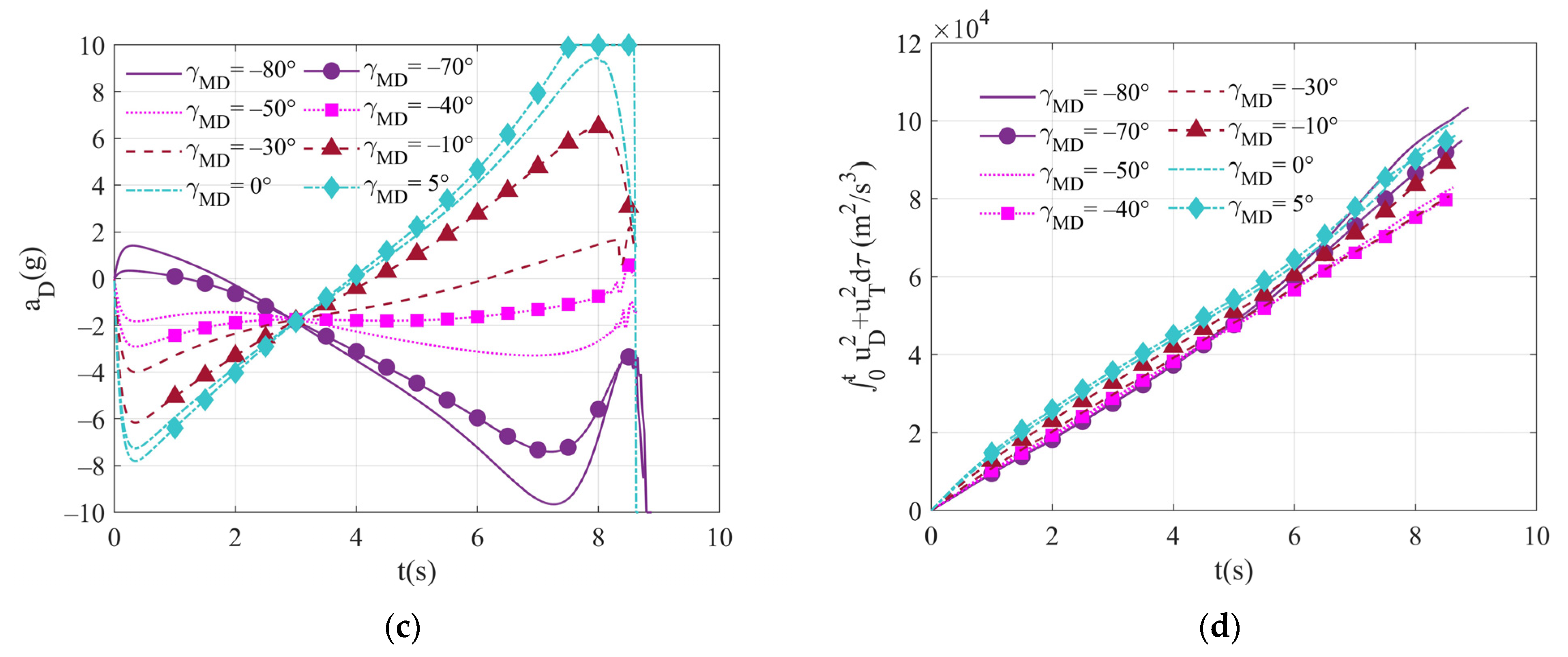
6.2.2. Simulation of Different Terminal Impact Angle Commands

The terminal impact angle commands are the same as those in the last subsection, and the weight coefficients α ,   α γ ,   β T are set to 1000, 10 10 , 100, respectively. Figure 6a shows the trajectory diagram of the one-way cooperation guidance law, and the corresponding miss distance and the actual terminal impact angle are shown in Figure 6b. The miss distances in [ 110 80 ] are all less than 0.2 m, and the impact angle errors are very small, which directly affects the hit-to-kill interception [35]. If the impact angle command exceeds this interval, the terminal quantities errors will increase. The overload of the target, defense missile, missile, and the total control effort curves are shown in Figure 6c–f. It can be seen that as γ c M D increases, the maximum overload demand and the control effort of the three entities also increase. Meanwhile, the overload value of the target is relatively stable during the whole process. For the same terminal impact angle command, the requirements of the target’s overload value do not vary much compared with those in two-way cooperation, but the overload requirement of the defense missile in one-way cooperation is higher. The other simulation results are similar to those in the two-way cooperation.
The miss distances and terminal impact angles corresponding to different α γ are shown in Figure 7a,b, and the values for different β T are presented in Figure 7c,d, respectively. The defender uses the proportional guidance law to intercept the missile, so it can always ensure a small miss distance for various coefficients. However, α γ must be large enough; otherwise, the terminal impact angle error will be large. Also, β T should also be small enough so that it can allow the target to maneuver with enough energy and lure the incoming missile. For different β T , the control effort when the terminal constraints are satisfied are shown in Figure 7e,f, respectively. In the cases with the same γ c M D , it can be found that the two control effort values are insensitive to β T , and the control energy allocation of the defense missile and the target can be adjusted more freely in the two-way cooperation.

6.3. One-Way Cooperation with Independent Target

As an example, this paper supposes that the target executes a bang-bang evasive maneuver with one time switch. The target maneuver strategy is shown below
u T = u T max   , t t b u T max   , t > t b
where t b is the switching time of bang-bang maneuver, and it is set to 6 s. Here, the method in Equation (58) for an arbitrary maneuver mode is adopted for calculation.
The terminal impact angle commands are successively given as 80 ,   70 ,   50 ,   40 ,   30 ,   10 ,   0 ,   5 , and the weight coefficients α and   α γ are set to 1000 and 10 10 , respectively. Figure 8a shows the trajectory diagram of the one-way cooperation guidance law, and the miss distance corresponding to each terminal impact angle instruction and the actual terminal impact angle are presented in Figure 8b. The miss distance in the range of [ 80 0 ] is 0.25 m, and a hit-to-kill interception can be achieved. However, for other instructions, the performance will decline, and the missile may even miss the target. When the target adopts the maneuver mechanism, compared with the previous two cooperative modes, the range of available terminal impact angle commands is the smallest. The overload of the defender and the total control effort curves are illustrated in Figure 8c,d, respectively. Under the above simulation conditions, when γ c M D = 40 , the maximum overload demand of the defender and the minimum control effort is shown. When γ c M D = 5 , the defender overload becomes saturated, the final miss range reaches 1.43 m, and the terminal impact angle error reaches 0.556 . Since the weight coefficient of the defender is 1, α and   α γ cannot be too small; otherwise, the overload of the defense missile cannot meet the demand, which will not be shown here due to the limited space of this paper.

7. Conclusions

This paper investigated the three-body engagement where the defender with an impact angle constraint is deployed by the aircraft to intercept the incoming missile. Optimal cooperative guidance laws with an impact angle constraint for three cooperation mechanisms were presented and mathematically formulated. In the first scenario, the two-way cooperation for the target and the defender was studied. In the second scenario, the one-way cooperation assumed that there is an independently homing defender using linear guidance law to intercept the incoming missile, and the guidance strategy is known for the target. In this case, the optimal one-way cooperative strategy was derived for the target to support the defender to intercept the missile with a specific impact angle constraint. In the third scenario, the escape strategy of the target is known to the defender, which is utilized by the defender to intercept the missile with a specific impact angle constraint. The cooperative strategy proposed in this paper is based on the premises of the entities with linear dynamics, perfect information-sharing mechanisms, and the known linear guidance strategy of the missile.
Then, a nonlinear two-dimensional model for flight vehicles with first-order autopilot dynamics was simulated to verify the performance of the proposed strategies. The simulation results indicated that the cooperative mechanism directly affects the available range of impact angles, and the constraint of a big impact angle can be realized by introducing the nonlinear model parameters and considering the angle variation between the velocity vector and the initial line-of-sight, although the guidance law was derived from the linear model. Because the future guidance strategies of the defender and the missile are known through the cooperative mechanism, the target can predict the behavior of the defender. In a similar way, based on the future maneuver strategies of the target and the guidance strategy of the missile, the defender can predict the missile’s behavior. Furthermore, compared to the one-way cooperation mechanism, the two-way cooperation mechanism achieves the best performance, so it can intercept incoming missiles with a larger terminal angle of attack and can be flexibly designed for the maximum overload capability of different defensive missiles and targets. In one-way cooperation, the independent defender can also intercept the others with the impact angle in a wide range, but the energy distribution of both parties cannot be adjusted. In addition, for an independent target in one-way cooperation, its terminal impact angle range is closely related to the maneuvering escape strategy of the target. The three cooperative strategies mentioned above can achieve a small miss distance and even make direct collision killing under a reasonable terminal impact angle command. The two-way cooperation needs additional hardware to be equipped on the defender for the communication, which will increase the cost of the defender. The one-way cooperation mechanism for independent defender is the easiest to implement, because no additional hardware support is required, and the defender implemented a guidance law such as PN is very possible. The other one-way cooperation mechanism gives the target aircraft more freedom to maneuver, but only in a form known to the defender in advance.
In this paper, the guidance strategies of the incoming missile were assumed to be the typical guidance laws, which are expressed as the linear guidance law form under the small angle linearization assumption. Based on this, the research of three active defense guidance strategies was completed. This assumption of typical guidance laws has certain applicability but designing active defense guidance strategies will be challenging for other guidance laws, especially some new guidance laws against targets protected by defenders, which is one of the research directions in the future. In addition, the method proposed in this paper can be extended to three-dimensional engagement, and the launch time for the defender missile is also worth studying. Finally, the defender missile should have omnidirectional interception capability.

Author Contributions

The contributions of the authors are the following: conceptualization, all authors; methodology, Q.L., Y.F. and J.Y.; software, Q.L., T.Y. and M.G.; writing—original draft preparation, Q.L. and M.G.; writing—review and editing, Q.L., M.G. and J.Y.; validation, T.Y.; investigation, M.G. All authors have read and agreed to the published version of the manuscript.

Funding

This work was supported by “the Fundamental Research Funds for the Central Universities”.

Data Availability Statement

All data used during the study appear in the submitted article.

Conflicts of Interest

All of the authors declare that they have no known competing financial interests or personal relationships that could appear to influence the work reported in this paper.

Appendix A. Computation of ZIA for Two-Way Cooperation

This Appendix deduces the computation of ZIA in the three-body engagement where the target and the defender take no maneuver and the missile uses linear guidance law. According to Equation (13), ZIA is calculated as
Z γ T D ( t ) = ϕ 81 x 1 + ϕ 82 x 2 + ϕ 8 M x M + ϕ 8 T x T + ϕ 85 x 5 + ϕ 86 x 6 + ϕ 8 D x D + ϕ 88 x 8
The computation of ZIA is transformed into solving the coefficients of state variables. We have
D γ d Φ d t g o = D γ d Φ d t d t d t g o = D γ Φ t f M D , t A Φ , Φ 0 = I
which can be expanded as
d ϕ 81 d t g o = d M K 1 ϕ 82 + K 1 ϕ 8 M B M / δ M + d M K 1 ϕ 86 d ϕ 82 d t g o = ϕ 81 d M K 2 ϕ 82 + K 2 ϕ 8 M B M / δ M + d M K 2 ϕ 86 d ϕ 8 M d t g o = C M d M K M δ M ϕ 82 + ϕ 8 M A M + B M K M + C M + d M K M δ M ϕ 86 + 1 / V M d ϕ 8 T d t g o = C T d M K T δ T ϕ 82 + ϕ 8 M B M K T δ T / δ M + ϕ 8 T A T + d M K T δ T ϕ 86 d ϕ 85 d t g o = 0 d ϕ 86 d t g o = ϕ 85 d ϕ 8 D d t g o = ϕ 86 C D δ D + ϕ 8 D A D + 1 / V D d ϕ 88 d t g o = 0
where all initial values are zero, except for ϕ 88 ( 0 ) = 1 . The solutions to ϕ 85 , ϕ 86 , and ϕ 88 are ϕ 85 = 0 , ϕ 86 = 0 , and ϕ 88 = 1 . If the missile uses linear guidance laws, we have K 2 = K 1 t g o M T . Then, the relationship for ϕ 81 and ϕ 82 can be represented as
ϕ 82 = ϕ 81 t g o M T
Then, with the results already obtained, Equation (A3) can be rewritten as
d ϕ 82 d t g o = ϕ 82 t g o M T d M K 2 ϕ 82 + K 2 ϕ 8 M B M / δ M d ϕ 8 M d t g o = C M d M K M δ M ϕ 82 + ϕ 8 M A M + B M K M + 1 / V M d ϕ 8 T d t g o = C T d M K T δ T ϕ 82 + ϕ 8 M B M K T δ T / δ M + ϕ 8 T A T d ϕ 8 D d t g o = ϕ 8 D A D + 1 / V D
where, all initial conditions are set to zero. The new coefficients ϕ ^ ( · ) only related to t g o are introduced, which are defined by
ϕ ^ 8 i = ϕ 8 i / δ i , i = M , T
By solving the last equation in Equation (A5), we have
ϕ 8 D = τ D V D ξ t g o / τ D
where the function ξ · is represented in Equations (24) and (A5) is transformed as
d ϕ 82 d t g o = ϕ 82 t g o M T d M K 2 ϕ 82 + K 2 ϕ ^ 8 M B M d ϕ ^ 8 M d t g o = C M d M K M ϕ 82 + ϕ ^ 8 M A M + B M K M + 1 / V M d ϕ ^ 8 T d t g o = C T d M K T ϕ 82 + ϕ ^ 8 M B M K T + ϕ ^ 8 T A T
The coefficients ϕ 82 , ϕ ^ 8 M , and ϕ ^ 8 T can be obtained by numerical integration of Equation (A8). By substituting the coefficients of Φ into Equation (A1), the form of ZID can be represented as
Z γ T D ( t ) = ϕ 82 y M T + y ˙ M T t g o M T t g o M T + ϕ ^ 8 M a M N + ϕ ^ 8 T a T N τ D V D ξ t g o / τ D a D + γ M + γ D
The above formula can still be improved by the kinematic variables of the nonlinear model. Considering the small angle approximations, the following relation can be obtained.
y M T = r M T λ M T λ 0
By using Equation (A10) and its derivative, we have
y M T + y ˙ M T t g o M T = V λ M T t g o M T
Finally, by substituting Equation (A11) into Equation (A9), ZIA can be calculated as in Equation (A12).
Z γ T D ( t ) = V λ M T ϕ 82 + ϕ ^ 8 M a M N + ϕ ^ 8 T a T N τ D V D ξ t g o / τ D a D + γ M + γ D

References

  1. Yamasaki, T.; Takano, H. Modified command to line-of-sight intercept guidance for aircraft defense. J. Guid. Control. Dyn. 2013, 36, 898–902. [Google Scholar] [CrossRef]
  2. Ratnoo, A.; Shima, T. Guidance Strategies Against Defended Aerial Targets. J. Guid. Control. Dyn. 2012, 35, 1059–1068. [Google Scholar] [CrossRef]
  3. Ratnoo, A.; Shima, T. Line-of-Sight Interceptor Guidance for Defending an Aircraft. J. Guid. Control. Dyn. 2011, 34, 522–532. [Google Scholar] [CrossRef]
  4. Kumar, R.S.; Mukherjee, D. Cooperative active aircraft protection guidance using line-of-sight approach. IEEE Trans. Aerosp. Electron. Syst. 2020, 27, 957–967. [Google Scholar] [CrossRef]
  5. Luo, H.; Ji, H.; Wang, X.; Qu, X. Cooperative robust line-of-sight guidance law for aerial target defense. In Proceedings of the International Conference on Unmanned Aircraft Systems, IEEE, Athens, Greece, 1–4 September 2020; pp. 1501–1507. [Google Scholar]
  6. Kumar, R.S.; Mukherjee, D. Mukherjee Cooperative guidance strategies for active aircraft protection. In Proceedings of the American Control Conference, Philadelphia, PA, USA, 10–12 July 2019; pp. 4641–4646. [Google Scholar]
  7. Shaferman, V.; Shima, T. Cooperative Multiple-Model Adaptive Guidance for an Aircraft Defending Missile. J. Guid. Control. Dyn. 2010, 33, 1801–1813. [Google Scholar] [CrossRef]
  8. Fang, F.; Cai, Y.; Yu, Z. Adaptive estimation and cooperative guidance for active aircraft defense in stochastic scenario. Sensors 2019, 19, 979. [Google Scholar] [CrossRef] [PubMed] [Green Version]
  9. Prokopov, O.; Shima, T. Linear Quadratic Optimal Cooperative Strategies for Active Aircraft Protection. J. Guid. Control. Dyn. 2013, 36, 753–764. [Google Scholar] [CrossRef]
  10. Weiss, M.; Shima, T. Minimum Effort Pursuit/Evasion Guidance with Specified Miss Distance. J. Guid. Control. Dyn. 2016, 39, 1069–1079. [Google Scholar] [CrossRef]
  11. Weiss, M.; Shima, T.; Castaneda, D.; Rusnak, I. Combined and Cooperative Minimum-Effort Guidance Algorithms in an Active Aircraft Defense Scenario. J. Guid. Control. Dyn. 2017, 40, 1241–1254. [Google Scholar] [CrossRef]
  12. Fang, F.; Cai, Y.-L. Optimal cooperative guidance with guaranteed miss distance in three-body engagement. Proc. Inst. Mech. Eng. Part G J. Aerosp. Eng. 2016, 232, 492–504. [Google Scholar] [CrossRef]
  13. Garcia, E.; Casbeer, D.W.; Pachter, M. Cooperative Strategies for Optimal Aircraft Defense from an Attacking Missile. J. Guid. Control. Dyn. 2015, 38, 1510–1520. [Google Scholar] [CrossRef]
  14. Garcia, E.; Casbeer, D.W.; Pachter, M. Active target defense using first order missile models. Automatica 2017, 78, 139–143. [Google Scholar] [CrossRef]
  15. Weintraub, E.I.; Garcia, E.; Casbeer, D.; Pachter, M. Optimal evasion in an active target defense scenario. In AIAA Scitech 2021 Forum; AIAA: Reston, VA, USA, 2021; p. 1881. [Google Scholar]
  16. Perelman, A.; Shima, T.; Rusnak, I. Cooperative Differential Games Strategies for Active Aircraft Protection from a Homing Missile. J. Guid. Control. Dyn. 2011, 34, 761–773. [Google Scholar] [CrossRef]
  17. Saurav, A.; Kumar, S.R.; Maity, A. Cooperative guidance strategies for aircraft defense with impact angle constraints. In SciTech Forum; AIAA: San Diego, CA, USA, 2019; p. 0356. [Google Scholar]
  18. Rubinsky, S.; Gutman, S. Three-Player Pursuit and Evasion Conflict. J. Guid. Control. Dyn. 2014, 37, 98–110. [Google Scholar] [CrossRef]
  19. Sun, Q.; Shen, M.; Gu, X.; Hou, K.; Qi, N. Evasion-Pursuit Strategy against Defended Aircraft Based on Differential Game Theory. Int. J. Aerosp. Eng. 2019, 2019, 7980379. [Google Scholar] [CrossRef]
  20. Garcia, E.; Casbeer, W.D.; Fuchs, E.Z.; Pachter, M. Cooperative missile guidance for active defense of air vehicles. IEEE Trans. Aerosp. Electron. Syst. 2018, 54, 706–721. [Google Scholar] [CrossRef]
  21. Liu, S.; Yan, B.; Zhang, X.; Liu, W.; Yan, J. Fractional-order sliding mode guidance law for intercepting hypersonic vehicles. Aerospace 2022, 9, 53. [Google Scholar] [CrossRef]
  22. Kumar, S.R.; Shima, T. Cooperative Nonlinear Guidance Strategies for Aircraft Defense. J. Guid. Control. Dyn. 2017, 40, 124–138. [Google Scholar] [CrossRef]
  23. Li, Q.; Fan, Y.; Yan, T.; Liang, X.; Yan, J. Cooperative smooth nonsingular terminal sliding mode guidance with tracking differentiator for active aircraft defense. Aerospace 2022, 9, 221. [Google Scholar] [CrossRef]
  24. Ghosh, S.; Ghose, D.; Raha, S. Composite Guidance for Impact Angle Control Against Higher Speed Targets. J. Guid. Control. Dyn. 2016, 39, 98–117. [Google Scholar] [CrossRef]
  25. Kumar, S.R.; Rao, S.; Ghose, D. Sliding-Mode Guidance and Control for All-Aspect Interceptors with Terminal Angle Constraints. J. Guid. Control. Dyn. 2012, 35, 1230–1246. [Google Scholar] [CrossRef]
  26. Zhang, H.; Zhang, Y.; Zhang, P. Optimal guidance law for intercepting the active defense aircraft with terminal angle constraint. J. Phys. Conf. Ser. Beijing Chin. 2021, 1828, 012160. [Google Scholar] [CrossRef]
  27. Shaferman, V.; Shima, T. Cooperative Optimal Guidance Laws for Imposing a Relative Intercept Angle. J. Guid. Control. Dyn. 2015, 38, 1395–1408. [Google Scholar] [CrossRef]
  28. Shaferman, V.; Shima, T. Cooperative Differential Games Guidance Laws for Imposing a Relative Intercept Angle. J. Guid. Control. Dyn. 2017, 40, 2465–2480. [Google Scholar] [CrossRef]
  29. Shaferman, V.; Shima, T. Linear Quadratic Guidance Laws for Imposing a Terminal Intercept Angle. J. Guid. Control. Dyn. 2008, 31, 1400–1412. [Google Scholar] [CrossRef]
  30. Taub, I.; Shima, T. Intercept Angle Missile Guidance Under Time Varying Acceleration Bounds. J. Guid. Control. Dyn. 2013, 36, 686–699. [Google Scholar] [CrossRef]
  31. Fonod, R.; Shima, T. Estimation Enhancement by Cooperatively Imposing Relative Intercept Angles. J. Guid. Control. Dyn. 2017, 40, 1711–1725. [Google Scholar] [CrossRef]
  32. Fonod, R.; Shima, T. Estimation enhancement by imposing a relative intercept angle for defending missiles. In SciTech Forum; AIAA: Grapevine, TX, USA, 2017; p. 1018. [Google Scholar]
  33. Zarchan, P. Tactical and Strategic Missile Guidance, 7th ed.; AIAA: Reston, VA, USA, 2019; Chapter 8. [Google Scholar]
  34. Shima, T. Optimal Cooperative Pursuit and Evasion Strategies Against a Homing Missile. J. Guid. Control. Dyn. 2011, 34, 414–425. [Google Scholar] [CrossRef]
  35. Zhou, J.; Yang, J. Smooth Sliding Mode Control for Missile Interception with Finite-Time Convergence. J. Guid. Control. Dyn. 2015, 38, 1311–1318. [Google Scholar] [CrossRef]
Figure 1. Active aircraft defense engagement.
Aerospace 09 00710 g001
Figure 2. Transfer matrix elements for two-way cooperation.
Aerospace 09 00710 g002
Figure 3. Comparison of performance for different terminal impact angle commands in two-way cooperation: (a) trajectories of entities; (b) the terminal miss distance and terminal impact angle; (c) target lateral acceleration; (d) defender lateral acceleration; (e) missile lateral acceleration; and (f) total control effort.
Aerospace 09 00710 g003aAerospace 09 00710 g003b
Figure 4. Comparison of performance for different β T in two-way cooperation: (a) miss distance for different β T ; (b) terminal impact angle for different β T ; (c) control effort of the target for different β T ; (d) control effort of the defender for different β T ; and (e) total control effort for different β T .
Aerospace 09 00710 g004
Figure 5. Transfer matrix elements for one-way cooperation with independent defender.
Aerospace 09 00710 g005
Figure 6. Comparison of performance for different terminal impact angle commands in one-way cooperation with an independent defender: (a) trajectories of entities; (b) the terminal miss distance and terminal impact angle; (c) target lateral acceleration; (d) defender lateral acceleration; (e) missile lateral acceleration; and (f) total control effort.
Aerospace 09 00710 g006
Figure 7. Comparison of performance for different α γ and β T in one-way cooperation with an independent defender: (a) miss distance for different α γ ; (b) impact angle for different α γ ; (c) miss distance for different β T ; (d) impact angle for different β T ; and (e) control effort of the target for different β T ; (f) control effort of the defender for different β T .
Aerospace 09 00710 g007
Figure 8. Comparison of performance for different terminal impact angle commands in one-way cooperation with an independent target: (a) trajectories of entities; (b) the terminal miss distance and terminal impact angle; (c) defender lateral acceleration; and (d) total control effort.
Aerospace 09 00710 g008aAerospace 09 00710 g008b
Table 1. Navigation gains of special cases for a two-way cooperation.
Special Cases N T ( t ) N γ T ( t ) N D ( t ) N γ D ( t )
α α B ˜ M T P 11 t go 2 / β T 0 α B ˜ M D P 21 t go 2 0
β T 0 0 α B ˜ M D P 11 + α γ B ˜ γ M D P 21 t go 2 α B ˜ M D P 12 + α γ B ˜ γ M D P 22 t go 2
β T 0 α B ˜ M T P 11 + α γ B ˜ γ M T P 21 t go 2 / β T α B ˜ M T P 12 + α γ B ˜ γ M T P 22 t go 2 / β T 0 0
α β T 0 0 α B ˜ M D P 21 t go 2 0
α β T 0 α B ˜ M T P 11 t go 2 / β T 0 0 0
Table 2. Simulation parameters.
ParametersValuesParametersValuesParametersValuesParametersValues
V T 200 m/s a M max 30 g τ M , τ D , τ T 0.1 s γ D 0 10
V M , V D 300 m/s γ T 0 0 a D max , a T max 10 g γ M 0 150
Publisher’s Note: MDPI stays neutral with regard to jurisdictional claims in published maps and institutional affiliations.

