Progress of Porous/Lattice Structures Applied in Thermal Management Technology of Aerospace Applications
Abstract
:1. Introduction
1.1. Heat Transfer Enhancement by Porous/Lattice Structures
1.2. Transpiration Cooling
2. Heat Transfer Enhancement by Porous/Lattice Structures
2.1. Theory and Mechanisms
2.2. Active Cooling for Scramjet Combustors/Turbine Blades
2.3. Applications in Heat Exchangers and Heat Sinks
2.4. Manufacture of Porous/Lattice Structures Cooling Channel
2.5. Investigations of Porous/Lattice Structure Element
3. Transpiration Cooling
3.1. Theory and Mechanism
3.2. Experimental Study
3.3. Numerical Study
4. Developments and Challenges
4.1. Heat Transfer Enhancement by Porous/Lattice Structures
- (1)
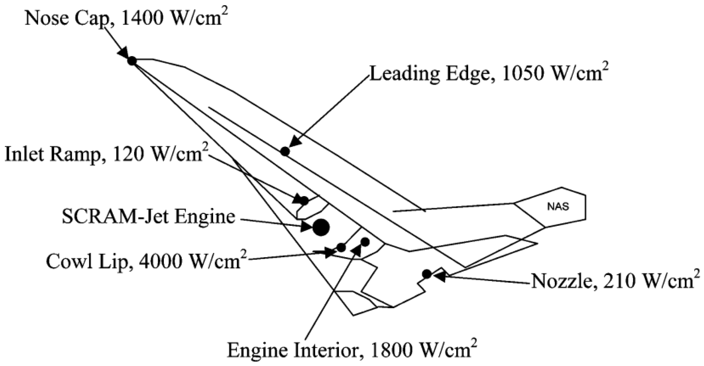
- For the applications of porous/lattice structures in scramjet/rocket engines, the investigations are still limited. The selection of the coolant is also limited by a relatively low heat flux. Most researchers select water or kerosene as coolants and the applied heat flux ranges from 0.5 to 1.5 MW/m2, which is lower than the actual thermal environment.
- (2)
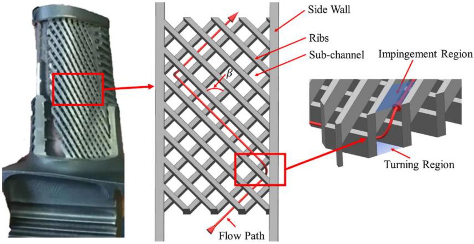
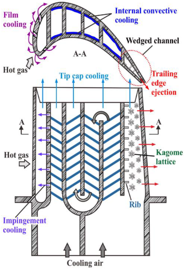
- For the applications of porous/lattice structures on the trailing edge of a blade, the related investigations are almost all numerical calculations. The blade wall temperature is close to 335 K with a coolant temperature set at room temperature, as shown in Table 1. These parameters are far from the real thermal environment of the trailing edge of turbine blades. The effect of thermal-physical properties changing with temperature is ignored. For investigations of a whole blade with a latticework design, these studies were carried out at a temperature difference of approximately 20 K, and high-temperature effects are also ignored. In addition, reliable experimental data are also needed in this field.
- (3)
- For heat exchangers and sinks, two lattice types, i.e., octet truss lattice and micro-lattice, are mainly used to obtain larger heat transfer areas. However, the current research on heat exchangers and sinks is mostly limited to the regular shape with low heat flux. Determining how to effectively dissipate heat in a high-temperature environment and with limited space, such as in aerospace applications, still needs further exploration.
- (4)
- Although manufacturing technology has developed significantly in recent years, additive manufacturing technology has limited applications in porous/lattice metal materials. Determining how to control the porosity and uniformity of the porous/lattice structures is still a big problem for additive manufacturing technology. Therefore, the investigations of porous/lattice structures in regenerative cooling and cooling of a turbine blade are still at the theoretical level, and more investigations are needed before its applications in practice.
- (5)
- Investigations on the heat transfer characteristics of porous/lattice structures mounting a cooling channel are mainly numerical calculations. The experimental research works are limited, especially for high-temperature and high-pressure-flow conditions, such as scramjet/rocket combustors and turbine blades.
- (6)
- The porous/lattice structures are proposed to achieve heat transfer enhancement. For this kind of material, heat transfer enhancement, structure strength, and weight are contradictory in practice. Therefore, it is necessary to conduct a comprehensive evaluation of the performance of all aspects when designing the structure to meet the requirements of use under different working conditions.
- (7)
- Highly efficient and accurate numerical models dealing with flow and heat transfer passing through porous/lattice structures are needed. Porous/lattice structure configuration optimization technology that considers multi-scale and multi-physical field effects needs to be developed.
4.2. Transpiration Cooling
- (1)
- High-temperature experiments are hard to find in the literature, but they are necessary when transpiration cooling is applied in high-temperature components, such as combustors, the leading edge of a hypersonic vehicle, and turbine blades. The high-temperature field of porous media is difficult to capture because of the weakness of the high-temperature measurement technique. The flow fields of the porous structure measured by experiments are hardly found, which prevents the study of the physical mechanism of transpiration cooling from an experimental perspective.
- (2)
- Transpiration cooling can be used for blades, leading edges, nose zones, combustion chambers, etc., but the existing experimental conditions find it difficult to meet the high-temperature environment and manufacture precision components, so many experiments are carried out based on a simplified flat plate structure made of stainless steel or bronze. In these experiments, the temperature of the stream mainly ranges from 373–800 K and the flow velocity mainly ranges from 20–65 m/s. Only in some investigations into the transpiration cooling of the leading edge of a hypersonic vehicle did the main steam total temperature reach 2310 K and the main steam velocity reach Ma = 4.2.
- (3)
- For experimental studies, the coolants used for transpiration cooling are primarily air, water, solid hydrogel, and propylene glycol aqueous. The materials of porous/lattice structures are primarily plastic and metal. Apart from metal and plastic porous/lattice structures, there are also certain materials with a high melting point and good thermal conductivity used for transpiration cooling. In recent years, to meet the extremely high-temperature conditions, the porous materials used in the experimental research of transpiration cooling have been developed with composite materials such as C/C composite material in order to obtain better cooling efficiency.
- (1)
- For the numerical study of single-phase transpiration cooling, the porous/lattice structures region is often simplified as a fluid zone with resistance and source items. The simplified model cannot accurately describe the flow field and temperature field in the porous zone. When geometric details of the porous/lattice structures are considered in calculations, large computational efforts are needed to deal with the physical model. Therefore, a more accurate model of porous/lattice needs to be developed.
- (2)
- The development of phase-change models of transpiration cooling is also limited, and the existing phase-change models require water as the coolant. With the extremely high thermal protection demand in aerospace applications, phase-change transpiration cooling has more potential to be used. The development of phase-change models should be coupled with a single-phase porous/lattice structure model to provide highly efficient and accurate predictions.
Author Contributions
Funding
Conflicts of Interest
References
- Yin, Y.; Mo, J.; Feng, J. Conductive fabric patch with controllable porous structure and elastic properties for tissue engineering applications. J. Mater. Sci. 2020, 55, 17120–17133. [Google Scholar] [CrossRef]
- Vikulin, A.V.; Yaroslavtsev, N.L.; Zemlyanaya, V.A. Investigation into transpiration cooling of blades in high-temperature gas turbines. Therm. Eng. 2019, 66, 397–401. [Google Scholar] [CrossRef]
- Huang, Z.; Zhu, Y.; Jiang, P.; Xiong, Y. Investigation of a porous transpiration cooled strut injector. J. Propuls. Power 2015, 31, 278–285. [Google Scholar] [CrossRef]
- Pettes-Duler, M.; Roboam, X.; Sareni, B. Integrated optimal design for hybrid electric powertrain of future aircrafts. Energies 2022, 15, 6719. [Google Scholar] [CrossRef]
- Han, Q.; Sun, C.; Tao, Y.; Li, Z.; Zhang, Y.; Chen, Y. Thermal protection of a hypersonic vehicle by modulating stagnation-point heat flux. Aerosp. Sci. Technol. 2020, 98, 105673. [Google Scholar] [CrossRef]
- Shi, S.; Wang, Y.; Yan, L.; Sun, P.; Li, M.; Tang, S. Coupled ablation and thermal behavior of an all-composite structurally integrated thermal protection system: Fabrication and modeling. Compos. Struct. 2020, 251, 112623. [Google Scholar] [CrossRef]
- Zhang, S.; Li, X.; Zuo, J.; Qin, J.; Cheng, K.; Feng, Y.; Bao, W. Research progress on active thermal protection for hypersonic vehicles. Prog. Aerosp. Sci. 2020, 119, 100646. [Google Scholar] [CrossRef]
- Song, K.D.; Choi, S.H.; Scotti, S.J. Transpiration cooling experiment for scramjet engine combustion chamber by high heat fluxes. J. Propuls. Power 2006, 22, 96–102. [Google Scholar] [CrossRef]
- Li, J.; Wang, X.; Liang, D.; Xu, N.; Zhu, B.; Li, W.; Yao, P.; Jiang, Y.; Min, X..; Huang, Z.; et al. A tandem radiative/evaporative cooler for weather-insensitive and high-performance daytime passive cooling. Sci. Adv. 2022, 8, eabq0411. [Google Scholar] [CrossRef] [PubMed]
- Liu, Y.; Jiang, P.; Xiong, Y.; Wang, Y. Experimental and numerical investigation of transpiration cooling for sintered porous flat plates. Appl. Therm. Eng. 2013, 50, 997–1007. [Google Scholar] [CrossRef]
- Liu, C.; Zhang, J.; Jia, D.; Li, P. Experimental and numerical investigation of the transition progress of strut-induced wakes in the supersonic flows. Aerosp. Sci. Technol. 2022, 120, 107256. [Google Scholar] [CrossRef]
- Yu, J.; Song, Q.; Ma, X.; Zhao, Y.; Cao, J.; Chen, X. Study of heat transfer of composite lattice structure for active cooling used in the scramjet combustor. Mater. Res. Innov. 2015, 19, S5-843–S5-849. [Google Scholar] [CrossRef]
- Baiju, A.P.; Jayan, N.; Nageswaran, G.; Suresh, M.S.; Narayanan, V. A technology for improving regenerative cooling in advanced cryogenic rocket engines for space transportation. Adv. Astronaut. Sci. Technol. 2021, 4, 11–18. [Google Scholar] [CrossRef]
- Hussain, S.; Ghopa, W.A.W.; Singh, S.S.K.; Azman, A.H.; Abdullah, S. Experimental and numerical vibration analysis of octet-truss-lattice-based gas turbine blades. Metals 2022, 12, 340. [Google Scholar] [CrossRef]
- Kaur, I.; Aider, Y.; Nithyanandam, K.; Singh, P. Thermal-hydraulic performance of additively manufactured lattices for gas turbine blade trailing edge cooling. Appl. Therm. Eng. 2022, 211, 118461. [Google Scholar] [CrossRef]
- Grossmann, B.V.; Biermann, H.; Mughrabi, H. Measurement of service-induced internal elastic strains in a single-crystal nickel-based turbine blade with convergent-beam electron diffraction. Philos. Mag. A 2000, 80, 1743–1757. [Google Scholar] [CrossRef]
- Lepoivre, A.; Edelin, D.; Baudin, N.; Soto, J.; Villière, M.; Redais, B.; Delaunay, D.; Sobotka, V. Rapid heat control for thermoplastic injection tooling using lattice structures as heat exchanger. Key Eng. Mater. 2022, 926, 1850–1863. [Google Scholar] [CrossRef]
- Zhao, B.; Zhang, J.; Lian, W. Numerical modeling of heat exchanger filled with octahedral lattice frame porous material. Aerospace 2022, 9, 238. [Google Scholar] [CrossRef]
- Qian, B.; Fan, H.; Liu, G.; Zhang, J.; Li, P. Microchannel liquid-cooled heat exchanger based on a nonuniform lattice: Study on structure calculation, formation process, and boiling heat transfer performance. Materials 2021, 14, 7248. [Google Scholar] [CrossRef]
- Chen, H.; Mo, H.; Wan, Z.; Huang, S.; Wang, X.; Zhu, H. Thermal performance of a boiling and condensation enhanced heat transfer tube—Stepped lattice finned tube. Appl. Therm. Eng. 2020, 173, 115227. [Google Scholar] [CrossRef]
- Shen, B.; Yan, H.; Xue, H.; Xie, G. The effects of geometrical topology on fluid flow and thermal performance in Kagome cored sandwich panels. Appl. Therm. Eng. 2018, 142, 79–88. [Google Scholar] [CrossRef]
- Yan, H.; Yang, X.; Lu, T.; Xie, G. Convective heat transfer in a lightweight multifunctional sandwich panel with X-type metallic lattice core. Appl. Therm. Eng. 2017, 127, 1293–1304. [Google Scholar] [CrossRef]
- Gao, L.; Sun, S.; Zhao, Y.; Sun, Y. Thermostructural multiobjective optimization of a composite sandwich panel with lattice truss cores. Numer. Heat Transf. Part B Fundam. 2016, 70, 233–250. [Google Scholar] [CrossRef]
- Deng, H.; Zhao, J.; Wang, C. Bionic design method of a non-uniform lattice structure for a landing footpad. Aerospace 2022, 9, 220. [Google Scholar] [CrossRef]
- Samipour, S.A.; Batrakov, V.V. Manufacture of aerospace lattice structures by radial braiding. Russ. Eng. Res. 2022, 42, 818–822. [Google Scholar] [CrossRef]
- Li, Y.; Shen, B.; Yan, H.; Boetcher, S.K.S.; Xie, G. Heat transfer enhancement of rotating wedge-shaped channels with pin fins and Kagome lattices. Numer. Heat Transf. Part A Appl. 2020, 77, 1014–1033. [Google Scholar] [CrossRef]
- Dixit, T.; Nithiarasu, P.; Kumar, S. Numerical evaluation of additively manufactured lattice architectures for heat sink applications. Int. J. Therm. Sci. 2021, 159, 106607. [Google Scholar] [CrossRef]
- Skamniotis, C.; Courtis, M.; Cocks, A.C.F. Multiscale analysis of thermomechanical stresses in double wall transpiration cooling systems for gas turbine blades. Int. J. Mech. Sci. 2021, 207, 106657. [Google Scholar] [CrossRef]
- Skamniotis, C.; Cocks, A.C.F. 2D and 3D thermoelastic phenomena in double wall transpiration cooling systems for gas turbine blades and hypersonic flight. Aerosp. Sci. Technol. 2021, 113, 106610. [Google Scholar] [CrossRef]
- Alhatim, O. Simulation of a conjugate problem of friction and heat transfer in transpiration cooling of gas turbine blades. High Temp. Mater. Process. Int. Q. High-Technol. Plasma Process. 2015, 19, 169–178. [Google Scholar] [CrossRef]
- Zhu, Y.; Jiang, P.; Sun, J.; Xiong, Y. Injector head transpiration cooling coupled with combustion in H2/O2 subscale thrust chamber. J. Thermophys. Heat Transf. 2013, 27, 42–51. [Google Scholar] [CrossRef]
- Luo, S.; Miao, Z.; Liu, J.; Song, J.; Xi, W.; Liu, C. Effects of coolants of double layer transpiration cooling system in the leading edge of a hypersonic vehicle. Front. Energy Res. 2021, 530, 756820. [Google Scholar] [CrossRef]
- Wang, J.; Zhao, L.; Wang, X.; Ma, J.; Lin, J. An experimental investigation on transpiration cooling of wedge shaped nose cone with liquid coolant. Int. J. Heat Mass Transf. 2014, 75, 442–449. [Google Scholar] [CrossRef]
- Singh, O.; Prasad, B.N. Comparative performance analysis of cogeneration gas turbine cycle for different blade cooling means. Int. J. Therm. Sci. 2009, 48, 1432–1440. [Google Scholar]
- Zheng, M.; Gan, H.; Narayan, P.S.; Li, Y.; Chyu, M.K. Experimental Investigation on Additively Manufactured Transpiration and Film Cooling Structures. J. Turbomach. 2019, 141, 031009. [Google Scholar]
- Frank, G.; Pfitzner, M. Investigation of the heat transfer coefficient in a transpiration film cooling with chemical reactions. Int. J. Heat Mass Transf. 2017, 113, 755–763. [Google Scholar] [CrossRef]
- Kumar, S.; Singh, O. Thermodynamic performance evaluation of gas turbine cycle with transpiration cooling of blades using air vis-à-vis steam. Proc. Inst. Mech. Eng. Part A J. Power Energy 2010, 224, 1039–1047. [Google Scholar] [CrossRef]
- Liu, J.; Xu, M.; Xi, W.; Song, J.; Luo, S.; Sunden, B.A. Numerical investigations of endwall film cooling design of a turbine vane using four-holes pattern. Int. J. Numer. Methods Heat Fluid Flow 2021, 32, 2177–2197. [Google Scholar] [CrossRef]
- Wambersie, A.; Wong, H.; Ireland, P.; Mayo, I. Experiments of transpiration cooling inspired panel cooling on a turbine blade yielding film effectiveness levels over 95%. Int. J. Turbomach. Propuls. Power 2021, 6, 16. [Google Scholar] [CrossRef]
- Arai, M.; Suidzu, T. Porous ceramic coating for transpiration cooling of gas turbine blade. J. Therm. Spray Technol. 2013, 22, 690–698. [Google Scholar] [CrossRef] [Green Version]
- Langener, T.; von Wolfersdorf, J.; Selzer, M.; Hald, H. Experimental investigations of transpiration cooling applied to C/C material. Int. J. Therm. Sci. 2012, 54, 70–81. [Google Scholar] [CrossRef]
- Xiong, Y.; Zhu, Y.; Jiang, P. Numerical simulation of transpiration cooling for sintered metal porous strut of the scramjet combustion chamber. Heat Transf. Eng. 2014, 35, 721–729. [Google Scholar] [CrossRef]
- He, F.; Wu, N.; Ran, F.; Wang, J. Numerical investigation on the transpiration cooling of three-dimensional hypersonic inlet. Aerosp. Sci. Technol. 2020, 106, 106152. [Google Scholar] [CrossRef]
- Ding, R.; Wang, J.; He, F.; Wang, M.; Luan, Y.; Dong, G.; Tang, L. Numerical investigation on a double layer combined cooling structure for aerodynamic heat control of hypersonic vehicle leading edge. Appl. Therm. Eng. 2020, 169, 114949. [Google Scholar] [CrossRef]
- Zhang, H.J.; Zou, Z.P. Numerical investigation of laminar-plate transpiration cooling by the preconditioned density-based algorithm. Numer. Heat Transf. Part A Appl. 2012, 62, 761–779. [Google Scholar] [CrossRef]
- Xu, G.; Liu, Y.; Luo, X.; Ma, J.; Li, H. Experimental investigation of transpiration cooling for sintered woven wire mesh structures. Int. J. Heat Mass Transf. 2015, 91, 898–907. [Google Scholar] [CrossRef]
- Liu, J.; Hussain, S.; Wang, L.; Xie, G.; Sundén, B.; Abrahamsson, H.; Arroyo, C. The effect of the pocket on the heat transfer of endwall with bluff body in the rear part of gas turbine. In Proceedings of the ASME Turbo Expo 2017: Turbomachinery Technical Conference and Exposition, Charlotte, NC, USA, 26–30 June 2017; Volume 50879, p. V05AT11A001. [Google Scholar]
- Wu, H.; Ding, M.; Su, Y. The study of cavity flow and transpiration cooling in supersonic combustion. Appl. Mech. Mater. 2013, 2644, 370–374. [Google Scholar] [CrossRef]
- Zhang, B.; Wang, H.; Jin, X.; Fan, X.; Huang, H.; Yao, J. Novel C/SiC porous ceramic with controllable properties served as transpiration cooling material. Ceram. Int. 2022, 48, 21616–21621. [Google Scholar] [CrossRef]
- Wu, Y.; Zou, Z.; Fu, C.; Zhang, W. Numerical study of porous blunt nosecone transpiration cooling under supersonic incoming flow. J. Porous Media 2017, 20, 607–618. [Google Scholar] [CrossRef]
- Yang, H.; Liu, X.; Bian, Y.; Wang, G. Numerical investigation on the mechanism of transpiration cooling for porous struts based on local thermal non-equilibrium model. Energies 2022, 15, 2091. [Google Scholar] [CrossRef]
- Liu, T.; Su, H.; Chen, Z.; He, F.; Wang, J. Numerical investigation on the transient transport and heat transfer characteristics of transpiration cooling with liquid phase change during coolant adjustment. Appl. Therm. Eng. 2022, 209, 118277. [Google Scholar] [CrossRef]
- Zhang, Z.; Sun, X.; Wang, X.; Xie, G. Flow structure and heat transfer of transpiration cooling by using a LBM: The effects of wall blowing and spatially nonuniform injection. Int. Commun. Heat Mass Transf. 2021, 127, 105491. [Google Scholar] [CrossRef]
- Campbell, N.S.; Hanquist, K.; Morin, A.; Meyers, J.; Boyd, I. Evaluation of computational models for electron transpiration cooling. Aerospace 2021, 8, 243. [Google Scholar] [CrossRef]
- Bandivadekar, D.; Minisci, E. Modelling and simulation of transpiration cooling systems for atmospheric re-entry. Aerospace 2020, 7, 29. [Google Scholar] [CrossRef]
- Cheng, Z.; Li, X.; Xu, R.; Jiang, P. Investigations on porous media customized by triply periodic minimal surface: Heat transfer correlations and strength performance. Int. Commun. Heat Mass Transf. 2021, 129, 105713. [Google Scholar] [CrossRef]
- da Silva, C.B.; MÉTais, O. On the influence of coherent structures upon interscale interactions in turbulent plane jets. J. Fluid Mech. 2002, 473, 103–145. [Google Scholar] [CrossRef] [Green Version]
- Shi, X.; Yang, Z.; Chen, W.; Chyu, M.K. Investigation of the effect of lattice structure on the fluid flow and heat transfer of supercritical CO2 in tubes. Appl. Therm. Eng. 2022, 207, 118132. [Google Scholar] [CrossRef]
- Zhao, J.; Chen, S. Non-darcy effects on nonparallel thermal instability of horizontal natural convection flow. J. Thermophys. Heat Transf. 2003, 17, 150–158. [Google Scholar] [CrossRef]
- Yang, Z.; Luo, X.; Chen, W.; Chyu, M.K. Mitigation effects of body-centered cubic lattices on the heat transfer deterioration of supercritical CO2. Appl. Therm. Eng. 2021, 183, 116085. [Google Scholar] [CrossRef]
- Wang, J.; Ge, J.; Fan, Y.; Fu, Y.; Liu, X. Flow behavior and heat transfer in a rectangular channel with miniature riblets. Int. Commun. Heat Mass Transf. 2022, 135, 106049. [Google Scholar] [CrossRef]
- Yi, L.; Yang, S.; Pan, M. Experimental investigation and parameter analysis of micro-jet impingement heat sink for improved heat transfer performance. Chem. Eng. Process. Process Intensif. 2022, 174, 108867. [Google Scholar] [CrossRef]
- Song, J.; Yuan, Y.; Liu, J.; Luo, S.; Sunden, B. Heat transfer enhancement of regenerative cooling channel with pyramid lattice sandwich structures. Heat Transf. Eng. 2022. [Google Scholar] [CrossRef]
- Yun, S.; Kwon, J.; Lee, D.; Shin, H.H.; Kim, Y. Heat transfer and stress characteristics of additive manufactured FCCZ lattice channel using thermal fluid-structure interaction model. Int. J. Heat Mass Transf. 2020, 149, 119187. [Google Scholar] [CrossRef]
- Furman, E.M.; Anghaie, S. Thermal hydraulic design analysis of ternary carbide fueled square-lattice honeycomb nuclear rocket engine. AIP Conf. Proc. 2008, 458, 1501. [Google Scholar]
- Widargo, R.; Anghaie, S. Nuclear design analysis of square-lattice honeycomb space nuclear rocket engine. AIP Conf. Proc. 2008, 458, 1507–1512. [Google Scholar]
- Li, Y.; Xie, G.; Boetcher, S.K.S.; Yan, H. Heat transfer enhancement of X-lattice-cored sandwich panels by introducing pin fins, dimples or protrusions. Int. J. Heat Mass Transf. 2019, 141, 627–642. [Google Scholar] [CrossRef]
- Xu, L.; Shen, Q.; Ruan, Q.; Xi, L.; Gao, J.; Li, Y. Optimization design of lattice structures in internal cooling channel of turbine blade. Appl. Sci. 2021, 11, 5838. [Google Scholar] [CrossRef]
- Shen, B.; Li, Y.; Yan, H.; Boetcher, S.K.S.; Xie, G. Heat transfer enhancement of wedge-shaped channels by replacing pin fins with Kagome lattice structures. Int. J. Heat Mass Transf. 2019, 141, 88–101. [Google Scholar] [CrossRef]
- Moss, A.; Macquart, T.; Panesar, A.; Forrest, M.; Greaves, P.; Pirrera, A. Structural design of wind turbine blades with an additively manufactured graded lattice core using topology optimisation. J. Phys. Conf. Ser. 2022, 2265, 032004. [Google Scholar] [CrossRef]
- Feng, X.B.; Xu, H.J. Modeling the propane combustion process within a micro-catalytic porous combustor by using the lattice Boltzmann method. J. Therm. Anal. Calorim. 2020, 139, 2659–2677. [Google Scholar] [CrossRef]
- Du, W.; Luo, L.; Wang, S.; Liu, J.; Sunden, B. Numerical investigation of flow field and heat transfer characteristics in a latticework duct with jet cooling structures. Int. J. Therm. Sci. 2020, 158, 106553. [Google Scholar] [CrossRef]
- Du, W.; Luo, L.; Wang, S.; Liu, J.; Sunden, B. Heat transfer and flow structure in a detached latticework duct. Appl. Therm. Eng. 2019, 155, 24–39. [Google Scholar] [CrossRef]
- Zhang, Y.; Gu, W.; Han, J. Heat transfer and friction in rectangular channels with ribbed or ribbed-grooved walls. J. Heat Transf. 1994, 116, 58–65. [Google Scholar] [CrossRef]
- Saha, K.; Acharya, S.; Nakamata, C. Heat transfer enhancement and thermal performance of lattice structures for internal cooling of airfoil trailing edges. J. Therm. Sci. Eng. Appl. 2013, 5, 011001. [Google Scholar] [CrossRef]
- Wang, G. A review of research progress in heat exchanger tube rupture accident of heavy liquid metal cooled reactors. Ann. Nucl. Energy 2017, 109, 1–8. [Google Scholar] [CrossRef]
- Mohamed, A.A.; Younis, O. Performance of drop shaped pin fin heat exchanger with four different fin dimensions. J. Mech. Eng. Sci. 2020, 14, 6934–6951. [Google Scholar] [CrossRef]
- Zhao, L.; Ryan, S.M.; Ortega, J.K.; Ha, S.; Sharp, K.W.; Guest, J.K.; Hemker, K.J.; Weihs, T.P. Experimental investigation of 3D woven Cu lattices for heat exchanger applications. Int. J. Heat Mass Transf. 2016, 96, 296–311. [Google Scholar] [CrossRef]
- Lai, X.; Wang, C.; Peng, D.; Yang, H.; Wei, Z. Analysis of heat transfer characteristics of a heat exchanger based on a lattice filling. Coatings 2021, 11, 1089. [Google Scholar] [CrossRef]
- Ho, J.Y.; Leong, K.C.; Wong, T.N. Additively-manufactured metallic porous lattice heat exchangers for air-side heat transfer enhancement. Int. J. Heat Mass Transf. 2020, 150, 119262. [Google Scholar] [CrossRef]
- Chaudhari, A.; Ekade, P.; Krishnan, S. Experimental investigation of heat transfer and fluid flow in octet-truss lattice geometry. Int. J. Therm. Sci. 2019, 143, 64–75. [Google Scholar] [CrossRef]
- Ekade, P.; Krishnan, S. Fluid flow and heat transfer characteristics of octet truss lattice geometry. Int. J. Therm. Sci. 2019, 137, 253–261. [Google Scholar] [CrossRef]
- Kaur, I.; Singh, P. Numerical investigation on conjugate heat transfer in octet-shape-based single unit cell thick metal foam. Int. Commun. Heat Mass Transf. 2021, 121, 105090. [Google Scholar] [CrossRef]
- Akçay, F.A.; Wu, D.; Bai, Y. Comprehensive studies on strength of 3d-printed aluminum micro lattice structures. Procedia Struct. Integr. 2020, 28, 1399–1406. [Google Scholar] [CrossRef]
- Maloney, K.J.; Fink, K.D.; Schaedler, T.A.; Kolodziejska, J.A.; Jacobsen, A.J.; Roper, C.S. Multifunctional heat exchangers derived from three-dimensional micro-lattice structures. Int. J. Heat Mass Transf. 2012, 55, 2486–2493. [Google Scholar] [CrossRef]
- Wang, X.; Chen, M.; Tate, D.; Rahimi, H.; Zhang, S. Numerical investigation on hydraulic and thermal characteristics of micro latticed pin fin in the heat sink. Int. J. Heat Mass Transf. 2020, 149, 119157. [Google Scholar] [CrossRef]
- Gopalan, K.S.; Eswaran, V. Numerical investigation of thermal performance of PCM based heat sink using structured porous media as thermal conductivity enhancers. Int. J. Therm. Sci. 2016, 104, 266–280. [Google Scholar] [CrossRef]
- Shamvedi, D.; McCarthy, O.J.; O’Donoghue, E.; Danilenkoff, C.; O’Leary, P.; Raghavendra, R. 3D Metal printed heat sinks with longitudinally varying lattice structure sizes using direct metal laser sintering. Virtual Phys. Prototyp. 2018, 13, 301–310. [Google Scholar] [CrossRef]
- Modrek, M.; Viswanath, A.; Khan, K.A.; Ali, M.I.H.; Al-Rub, R.K.A. An optimization case study to design additively manufacturable porous heat sinks based on triply periodic minimal surface (TPMS) lattices. Case Stud. Therm. Eng. 2022, 36, 102161. [Google Scholar] [CrossRef]
- Wu, L.; Dai, N.; Wang, H. Evaluation of rods deformation of metal lattice structure in additive manufacturing based on skeleton extraction technology. Math. Biosci. Eng. MBE 2021, 18, 7525–7538. [Google Scholar] [CrossRef]
- Niu, J.; Choo, H.L.; Sun, W. Finite element analysis and experimental study of plastic lattice structures manufactured by selective laser sintering. Proc. Inst. Mech. Eng. Part L J. Mater. Des. Appl. 2017, 231, 171–178. [Google Scholar] [CrossRef] [Green Version]
- Tian, J.; Kim, T.; Lu, T.J.; Hodson, H.P.; Queheillalt, D.T.; Sypeck, D.J.; Wadley, H.N.G. The effects of topology upon fluid-flow and heat-transfer within cellular copper structures. Int. J. Heat Mass Transf. 2004, 47, 3171–3186. [Google Scholar] [CrossRef]
- Cheraghipoor, M.; Mohebbi-Kalhori, D.; Noroozifar, M.; Maghsoodlou, M.T. Production of greener energy in microbial fuel cell with ceramic separator fabricated using native soils: Effect of lattice and porous SiO2. Fuel 2021, 284, 118938. [Google Scholar] [CrossRef]
- Ho, J.Y.; Leong, K.C.; Wong, T.N. Experimental and numerical investigation of forced convection heat transfer in porous lattice structures produced by selective laser melting. Int. J. Therm. Sci. 2019, 137, 276–287. [Google Scholar] [CrossRef]
- Jin, X.; Li, Y.; Yan, H.; Xie, G. Comparative study of flow structures and heat transfer enhancement in a metallic lattice fabricated by metal sheet folding: Effects of punching location shift. Int. J. Heat Mass Transf. 2019, 134, 209–225. [Google Scholar] [CrossRef]
- Wei, K.; He, R.; Cheng, X.; Pei, Y.; Zhang, R.; Fang, D. Fabrication and heat transfer characteristics of C/SiC pyramidal core lattice sandwich panel. Appl. Therm. Eng. 2015, 81, 10–17. [Google Scholar] [CrossRef]
- Jebauer, S.; Czerwinska, J. Three-dimensional vortex structures on heated micro-lattice in a gas. Int. J. Heat Mass Transf. 2014, 70, 827–834. [Google Scholar] [CrossRef]
- Yan, B. A new lattice with enhanced heat transfer characteristics. Nucl. Eng. Des. 2013, 265, 254–261. [Google Scholar] [CrossRef]
- Gao, L.; Sun, Y. Fluid flow and heat transfer characteristics of composite lattice core sandwich structures. J. Thermophys. Heat Transf. 2014, 28, 258–269. [Google Scholar] [CrossRef]
- Ernot, J.; Verdin, P.G.; Ahmad, H.; Indge, P. Analytical and numerical predictions of the thermal performance of multi-layered lattice structures. Int. J. Heat Mass Transf. 2019, 145, 118752. [Google Scholar] [CrossRef]
- Downing, D.; Leary, M.; McMillan, M.; Alghamdi, A.; Brandt, M. Heat transfer in lattice structures during metal additive manufacturing: Numerical exploration of temperature field evolution. Rapid Prototyp. J. 2020, 26, 911–928. [Google Scholar] [CrossRef]
- Ma, Y.; Yan, H.; Xie, G. Flow and thermal performance of sandwich panels with plate fins or/and pyramidal lattice. Appl. Therm. Eng. 2020, 164, 114468. [Google Scholar] [CrossRef]
- Wang, X.; Wei, K.; Wang, K.; Yang, X.; Qu, Z.; Fang, D. Effective thermal conductivity and heat transfer characteristics for a series of lightweight lattice core sandwich panels. Appl. Therm. Eng. 2020, 173, 115205. [Google Scholar] [CrossRef]
- Zhang, J.; Li, P.; Qian, B.; Li, B.; Qiu, Z.; Xuan, F. RETRACTED ARTICLE: Selective laser melting of G-surface lattice: Forming process and boiling heat transfer characteristics. J. Nanoparticle Res. 2020, 22, 1–10. [Google Scholar] [CrossRef]
- Liang, D.; Chen, W.; Ju, Y.; Chyu, M.K. Comparing endwall heat transfer among staggered pin fin, Kagome and body centered cubic arrays. Appl. Therm. Eng. 2021, 185, 116306. [Google Scholar] [CrossRef]
- Yun, S.; Lee, D.; Jang, D.S.; Lee, M.; Kim, Y. Numerical analysis on thermo-fluid–structural performance of graded lattice channels produced by metal additive manufacturing. Appl. Therm. Eng. 2021, 193, 117024. [Google Scholar] [CrossRef]
- Gao, L.; Sun, Y. Thermal control of composite sandwich structure with lattice truss cores. J. Thermophys. Heat Transf. 2015, 29, 47–54. [Google Scholar] [CrossRef]
- Bai, X.; Zheng, Z.; Nakayama, A. Heat transfer performance analysis on lattice core sandwich panel structures. Int. J. Heat Mass Transf. 2019, 143, 118525. [Google Scholar] [CrossRef]
- Xiao, H.; Chen, W.; Yan, B. Heat transfer and friction in nonuniform wall roughness lattice. Prog. Nucl. Energy 2015, 83, 43–51. [Google Scholar] [CrossRef]
- Liu, X.; Bian, Y.; Zhou, W.; Wu, C.; Jia, Z. Investigation on heat transfer during transpiration cooling with hydrocarbon fuel coolant. Int. J. Heat Mass Transf. 2023, 200, 123507. [Google Scholar] [CrossRef]
- Glass, D.E.; Dilley, A.D.; Kelly, H.N. Numerical analysis of convection/transpiration cooling. Proc. 9th Int. Space Planes Hypersonic Syst. Technol. Conf. 2001, 38, 15–20. [Google Scholar] [CrossRef] [Green Version]
- Gritskevich, M.S.; Garbaruk, A.V.; Schütze, J.; Menter, F.R. Development of DDES and IDDES Formulations for the k-ω Shear Stress Transport Model. Flow Turbul. Combust. 2012, 88, 431–449. [Google Scholar] [CrossRef]
- Qian, K.; Liu, T.; He, F.; Wang, M.; Tang, L.; Zhou, J. Numerical investigation on radiation effect in transpiration cooling. J. Phys. Conf. Ser. 2021, 2097, 012011. [Google Scholar] [CrossRef]
- Peng, Y.; Xu, G.; Luo, X.; He, J.; Liu, D. Experimental investigation on the transpiration cooling characteristics of sintered wire mesh in plain weave. Micromachines 2022, 13, 450. [Google Scholar] [CrossRef]
- Jiang, P.; Huang, G.; Zhu, Y.; Liao, Z.; Huang, Z. Experimental investigation of combined transpiration and film cooling for sintered metal porous struts. Int. J. Heat Mass Transf. 2017, 108, 232–243. [Google Scholar] [CrossRef]
- Huang, G.; Zhu, Y.; Liao, Z.; Ouyang, X.; Jiang, P. Experimental investigation of transpiration cooling with phase change for sintered porous plates. Int. J. Heat Mass Transf. 2017, 114, 1201–1213. [Google Scholar] [CrossRef]
- Kim, M.; Shin, D.H.; Lee, B.J.; Lee, J. Experimental and numerical investigation of micro-scale effusion and transpiration air cooling on cascaded turbine blades. Case Stud. Therm. Eng. 2022, 32, 101892. [Google Scholar] [CrossRef]
- Kim, M.; Shin, D.H.; Lee, B.J.; Lee, J. Flow characterization of microscale effusion and transpiration air cooling on single blade. Case Stud. Therm. Eng. 2022, 31, 101863. [Google Scholar] [CrossRef]
- Kumar, S.; Singh, O. Enhancement of combined cycle performance using transpiration cooling of gas turbine blades with steam. J. Mech. Sci. Technol. 2014, 28, 2429–2437. [Google Scholar] [CrossRef]
- Kim, M.; Shin, D.H.; Kim, J.S.; Lee, B.J.; Lee, J. Experimental investigation of effusion and transpiration air cooling for single turbine blade. Appl. Therm. Eng. 2021, 182, 116156. [Google Scholar] [CrossRef]
- Wu, N.; Wang, J.; He, F.; Dong, G.; Tang, L. An experimental investigation on transpiration cooling of a nose cone model with a gradient porosity layout. Exp. Therm. Fluid Sci. 2019, 106, 194–201. [Google Scholar] [CrossRef]
- Zhang, T.; Feng, Q.; Cai, W.; He, W. Numerical analysis of transpiration cooling in annular slinger combustor. IOP Conf. Ser. Earth Environ. Sci. 2019, 234, 012058. [Google Scholar] [CrossRef]
- Shen, L.; Wang, J.; Dong, W.; Pu, J.; Peng, J.; Qu, D.; Chen, L. An experimental investigation on transpiration cooling with phase change under supersonic condition. Appl. Therm. Eng. 2016, 105, 549–556. [Google Scholar] [CrossRef]
- Xing, Y.; Weigand, B. Experimental investigation of impingement heat transfer on a flat and dimpled plate with different crossflow schemes. Int. J. Heat Mass Transf. 2010, 53, 3874–3886. [Google Scholar] [CrossRef]
- Qian, K.; Wang, J.; He, F.; Wu, Y.; Zhou, Z. An experimental investigation on transpiration cooling performances using solid hydrogel as coolant. Appl. Therm. Eng. 2019, 158, 113753. [Google Scholar] [CrossRef]
- He, F.; Wu, N.; Zhou, Z.; Wang, J. Experimental investigation on transpiration cooling using propylene glycol aqueous solution. Int. J. Therm. Sci. 2021, 164, 106890. [Google Scholar] [CrossRef]
- Huang, Z.; Zhu, Y.; Xiong, Y.; Jiang, P. Investigation of transpiration cooling for sintered metal porous struts in supersonic flow. Appl. Therm. Eng. 2014, 70, 240–249. [Google Scholar] [CrossRef]
- Chamoli, S. ANN and RSM approach for modeling and optimization of designing parameters for a V down perforated baffle roughened rectangular channel. Alex. Eng. J. 2015, 54, 429–446. [Google Scholar] [CrossRef] [Green Version]
- Jiang, P.; Yu, L.; Sun, J.; Wang, J. Experimental and numerical investigation of convection heat transfer in transpiration cooling. Appl. Therm. Eng. 2004, 24, 1271–1289. [Google Scholar] [CrossRef]
- Liu, Y.; Jiang, P.; Jin, S.; Sun, J. Transpiration cooling of a nose cone by various foreign gases. Int. J. Heat Mass Transf. 2010, 53, 5364–5372. [Google Scholar] [CrossRef]
- Kilic, M. A numerical analysis of transpiration cooling as an air cooling mechanism. Heat Mass Transf. 2018, 54, 3647–3662. [Google Scholar] [CrossRef]
- Jiang, P.; Liao, Z.; Huang, Z.; Xiong, Y.; Zhu, Y. Influence of shock waves on supersonic transpiration cooling. Int. J. Heat Mass Transf. 2019, 129, 965–974. [Google Scholar] [CrossRef]
- Bellettre, J.; Bataille, F.; Lallemand, A.; Andoh, H.Y. Studies of the transpiration cooling through a sintered stainless steel plate. Exp. Heat Transf. 2005, 18, 33–44. [Google Scholar] [CrossRef]
- Yang, L.; Chen, W.; Chyu, M.K. A convolution modeling method for pore plugging impact on transpiration cooling configurations perforated by straight holes. Int. J. Heat Mass Transf. 2018, 126, 1057–1066. [Google Scholar] [CrossRef]
- Ding, R.; Wang, J.; He, F.; Dong, G.; Tang, L. Numerical investigation on the performances of porous matrix with transpiration and film cooling. Appl. Therm. Eng. 2019, 146, 422–431. [Google Scholar] [CrossRef]
- Shen, B.; Yin, L.; Liu, H.; Liu, W. Thermal protection characteristics for a combinational opposing jet and platelet transpiration cooling nose-tip. Acta Astronaut. 2019, 155, 143–152. [Google Scholar] [CrossRef]
- Yang, L.; Min, Z.; Yue, T.; Rao, Y.; Chyu, M.K. High resolution cooling effectiveness reconstruction of transpiration cooling using convolution modeling method. Int. J. Heat Mass Transf. 2019, 133, 1134–1144. [Google Scholar] [CrossRef]
- He, F.; Wang, J.; Xu, L.; Wang, X. Modeling and simulation of transpiration cooling with phase change. Appl. Therm. Eng. 2013, 58, 173–180. [Google Scholar] [CrossRef]
- He, F.; Wang, J. Numerical investigation on critical heat flux and coolant volume required for transpiration cooling with phase change. Energy Convers. Manag. 2014, 80, 591–597. [Google Scholar] [CrossRef]
- He, F.; Dong, W.; Wang, J.; Zhou, J.; Tang, L. Transient model and its application to investigate the injection mode and periodical operation of transpiration cooling with liquid coolant phase change. Appl. Therm. Eng. 2020, 181, 115956. [Google Scholar] [CrossRef]
- Dong, W.; Wang, J. A new model and its application to investigate transpiration cooling with liquid coolant phase change. Transp. Porous Media 2018, 122, 575–593. [Google Scholar] [CrossRef]
- Shi, J.; Wang, J. A numerical investigation of transpiration cooling with liquid coolant phase change. Transp. Porous Media 2011, 87, 703–716. [Google Scholar] [CrossRef]
- Huang, G.; Zhu, Y.; Liao, Z.; Xu, R.; Jiang, P. Biomimetic self-pumping transpiration cooling for additive manufactured porous module with tree-like micro-channel. Int. J. Heat Mass Transf. 2019, 131, 403–410. [Google Scholar] [CrossRef]
- Huang, G.; Zhu, Y.; Liao, Z.; Huang, Z.; Jiang, P. Transpiration cooling with bio. Bioinspiration Biomim. 2020, 15, 036016. [Google Scholar] [CrossRef]
- Shi, J.; Wang, J. A numerical investigation on the laminar boundary flow layer with transpiration cooling. Transp. Porous Media 2008, 78, 37–46. [Google Scholar] [CrossRef]
- Dahmen, W.; Müller, S.; Rom, M.; Schweikert, S.; Selzer, M.; von Wolfersdorf, J. Numerical boundary layer investigations of transpiration-cooled turbulent channel flow. Int. J. Heat Mass Transf. 2015, 86, 90–100. [Google Scholar] [CrossRef]
- Xiao, X.; Zhao, G.; Zhou, W.; Martynenko, S. Large-eddy simulation of transpiration cooling in turbulent channel with porous wall. Appl. Therm. Eng. 2018, 145, 618–629. [Google Scholar] [CrossRef]
- Rehman, M.M.U.; Qu, Z.G.; Fu, R.P.; Xu, H.T. Numerical study on free-surface jet impingement cooling with nanoencapsulated phase-change material slurry and nanofluid. Int. J. Heat Mass Transf. 2017, 109, 312–325. [Google Scholar] [CrossRef]

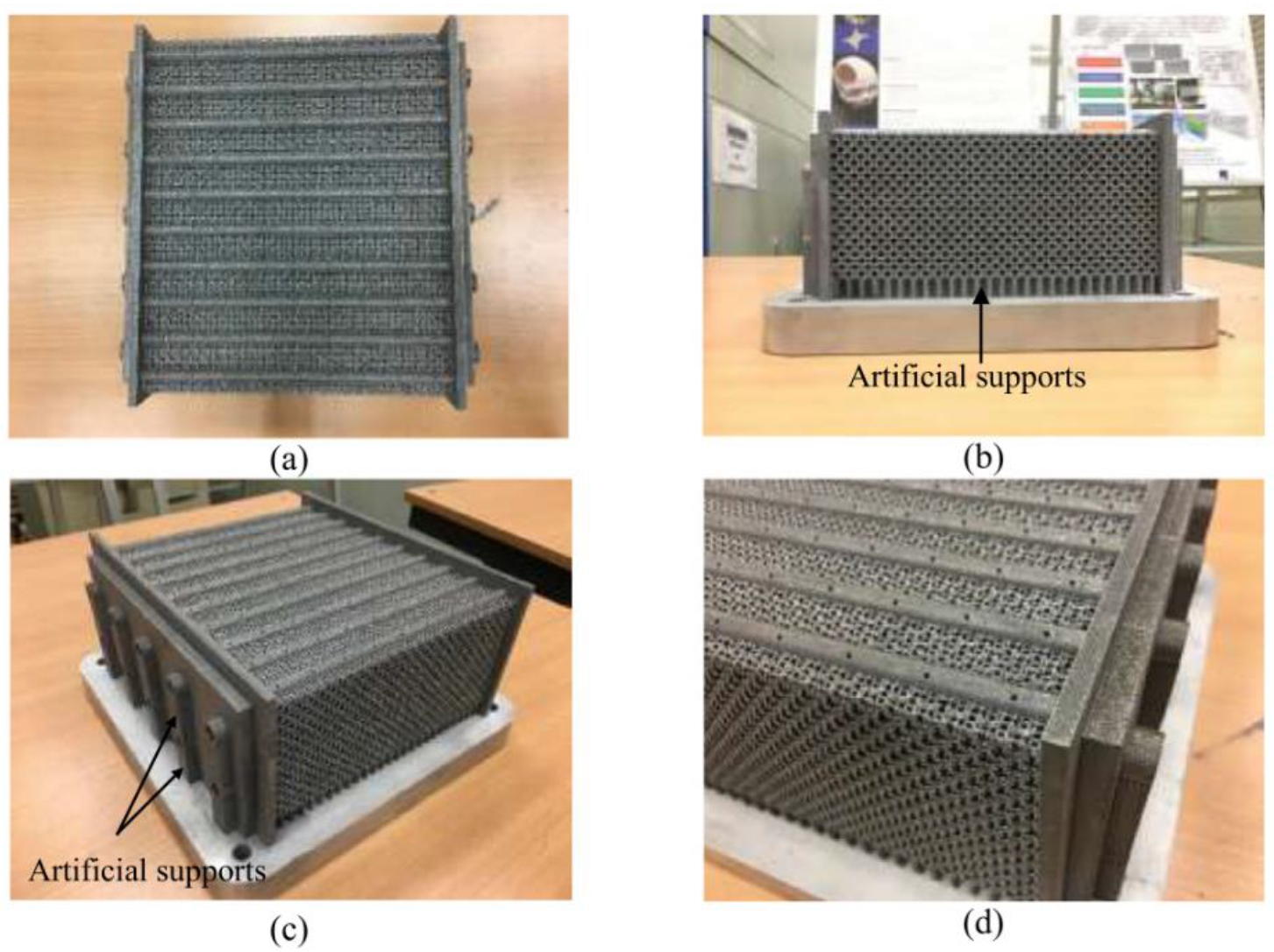
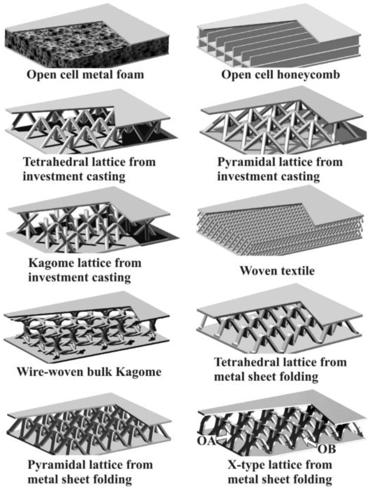
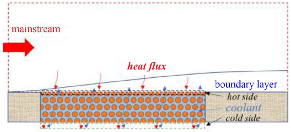
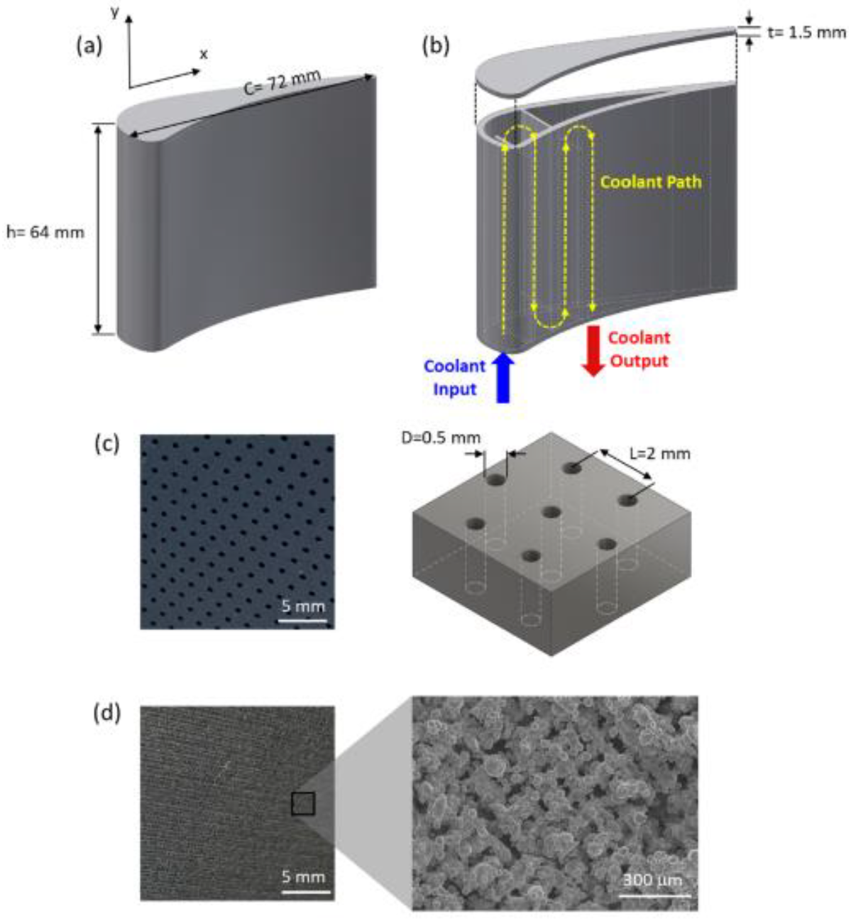
| Ref. | Applications | Lattice Type and Geometry | Lattice Material | Coolant | Flow Parameter | Heat Transfer Parameter and Boundary Conditions |
|---|---|---|---|---|---|---|
| [12] | Scramjet combustor | Kagome cored composite lattice structure (d = 2 mm, h = 8 mm, l = 9.8 mm) | C/C composite material | Aviation kerosene | Re = 562–56,234 | h = 380–4200 W/(m2·K); T = 1000 K |
| [64] | Scramjet combustor | Body-centered cubic lattice (d = 0.28–0.82 mm) | Maraging steel, 17-4 PH, and H13 | Water | v = 0.5–2.5 m/s | h = 0–55,000W/(m2·K); heat flux = 0.5 MW/m2 |
| [63] | Rocket combustor | Pyramid core lattice sandwich (d = 0.4/0.8 mm, l = 12.2 mm) | 1Cr18Ni9Ti | Kerosene | qm = 0.001 kg/s | Nu = 0–110; heat flux = 1.5 MW/m2 |
| [68] | Turbine Blade | Common lattice structure (d = 2 mm) | Nickel-Base superalloy IN718 | Air | Re = 6000–12,000 | Nu = 110–180; A constant heat flux corresponded the target surface |
| [72] | Turbine blade | Latticework (l = 224 mm, h = 48 mm) | Aluminium | Cooling air | Re = 44,000 | Nu/Nu0 = 0–5; T = 50 ℃ |
| [26] | Trailing edge of turbine blade | Kagome lattice, pin fins, ribs (d = 2.43–5.8 mm, h = 3 mm) | 310 stainless steel | Compressible air | Re = 5000 | h = 50–170 W/(m2·K); heat flux = 1500 W/m2 |
| [69] | Trailing edge of turbine blade | Kagome lattice, pin fins, ribs (d = 2.43–5.8 mm, h = 3 mm, l = 3.6 mm) | 310 stainless steel (0Cr25Ni20) | Air | Re = 5000–15,000 | h = 0–150 W/(m2·K); T = 335 K |
| [74] | Trailing edge of turbine blade | Lattice-matrix structures (e/D = 0.02/0.028, p/e = 8–30) | Stainless steel | Air | Re = 10,000–50,000 | Nu/Nu0 = 2.4; T = 120–125 °C |
| [75] | Trailing edge of turbine blade | Converging lattice structures, pin fins (x/D = 0.6–10) | Low thermal conductivity plastics | Air | Re = 4000–20,000 | Nu/Nu =1–4; A time-changing wall temperature |
| Ref. | Lattice Type and Geometry | Lattice Material | Coolant | Flow Parameter | Heat Transfer Parameter and Boundary Conditions |
|---|---|---|---|---|---|
| [21] | Single-layered Kagome and wire-woven bulk Kagome cores sandwich (d = 1.0/1.68 mm, l = 12.73 mm, h = 13 mm) | Copper-2% Beryllium (Be2Cu) alloy | Incompressible fluid with constant thermophysical properties | Re = 3995–8710 | Nu = 50–200; heat flux = 4000 W/m2 |
| [22] | X-type metallic lattice cored sandwich panel, tetrahedral lattice cored sandwich panel (w = 2.16 mm, l = 12 mm, h = 12 mm) | AISI 304 stainless steel | Air | Re = 2165‒6043 | Nu = 0–500; heat flux = 4088‒8529 W/m2 |
| [58] | Body-centered cubic lattice (h < 4.5 mm) | 316L stainless steel | Supercritical CO2 | mass flux = 130–419 g/(m2·s) | Nu = 100–400; heat flux = 41.94 kW/m2 |
| [67] | X-lattice-cored sandwich panels with pin fins, dimples or protrusions (l = 12 mm, w = 12 mm, h = 9.66 mm) | AISI 304 stainless steel | Air | Re = 3100–5700 | Nu = 40–260; heat flux = 9882.6 W/m2 |
| [69] | Kagome lattice structures, pin fins lattice structures (d = 3.52/3.28/2.43/5.8/4.25/2.5 mm, h = 3 mm, w = 30 mm) | ASTM type 310 stainless steel (0Cr25Ni20) | Air | Re = 5000–15,000 | h = 0–150 W/(m2·K); heat flux = 1500 W/m2 |
| [98] | A new lattice with non-uniform wall roughness (p/D = 1.12) | Stainless steel | Air | Re = 38,754 | Nu = 210–400; Tin = 47 ℃ |
| [99] | Composite lattice core sandwich structures (l = 10 mm, w = 10 mm, h = 1 mm) | CF-reinforced resin matrix composite (CFRP) | Incompressible fluid with constant thermophysical properties at 300 K | Re = 0–100,000 | Nu = 10–1000; heat flux = 10 kW/m2 |
| [100] | Multi-layered lattice structures (d = 2 mm, l = 17.3 mm) | Aluminium | Air | v = 5.4–11 m/s | h = 90–220 W/(m2·K); T = 350 K |
| [102] | Plate fins or/and pyramidal lattice (l = 12 mm, h = 9.64 mm, w = 12 mm) | A kind of solid with thermal conductivity = 16.2 W/(m·K) | Air | Re = 3100–5700 | Nu = 83.31–196.27; heat flux = 9882.6 W/m2 |
| [105] | Staggered pin fin array, Kagome lattice array, body centered cubic lattice array (d = 7.4/4/3.4 mm, l = 20 mm, h = 15 mm) | Acrylic plastics | Compressed air | Re = 5000–20,000 | Nu = 20–55; T = 293 K |
| [106] | Increase-type graded, V-type graded, W-type graded lattice (d = 0.3–0.57 mm) | 17-4 PH steel | Water | v = 0.1–0.5 m/s | h = 5000–14,000 W/(m2·K); heat flux = 300 kW/m2 |
| [107] | Composite sandwich structure with lattice truss cores (d = 1/1.5/2.5/3 mm, h = 9/10/14/16 mm) | Carbon-fiber-reinforced resin matrix composites (T700/3234) | A specific fluid with T = 300 K | v = 5 m/s | h = 161.68–171.13 W/(m2·K); heat flux = 10 kW/m2 |
| [108] | Vertical lattices, slanted lattices, Kagome lattices, tetrahedral lattices and pyramidal lattices (d = 0.35 mm) | Metal foam | Air | v = 1–12 m/s | h = 0–660 W/(m2·K); An equal pumping power |
| [109] | A new lattice with nonuniform wall roughness (e = 2.8 mm, p/e = 4–15) | Stainless steel | Air | Re = 2000–22,000 | Nu = 10–105; heat flux = 1390 W/m2 |
| Ref. | Applications | Plate Material | Coolant | Mainstream |
|---|---|---|---|---|
| [10] | Sintered porous flat plates | Stainless steel or bronze | Air | Dry air supplied by a blower (30 m/s, 100 °C) |
| [46] | Sintered woven wire mesh structures | Stainless steel | Cooling air (20.5–22.3 °C) | Air (130–150 kg/h, 100–130 °C) |
| [115] | Leading edge | Stainless steel (1Cr18Ni9Ti) | Room temperature dry air | Air (Ma2.8, 398.15 K) |
| [116] | Sintered porous plates | Bronze | Liquid water (293.2 K) | Hot air (65 m/s, 800 K) |
| [117] | C3X blades | Stainless steel (SUS304) | Cooling air | Dry air (3197 m3/h, heated by three electrical heaters) |
| [121] | Nose cone | 316L alloy powder | Cooling air and liquid water (20 °C) | Air (20 m/s, 100 °C) |
| [122] | Annular Slinger Combustor | GH3044 | Fresh air | Air (7.3 kg/s and 742 K) |
| [125] | A porous flat plate specimen | Nickel-based powders (Ni 73.46%, Cr 17.3%, Fe 7.5%, Si 1.7%, and C 0.04%) | Solid hydrogel | Air (523 K and 693 K) |
| [126] | A sintered porous plate and a solid frame | Nickel-based super alloy powders (73.46%Ni, 17.3%Cr, 7.5%Fe, 1.7%Si and 0.04%C) | Propylene glycol aqueous | Air (Re12000, 523 K) |
| Ref. | Applications | Plate Material | Coolant | Numerical Model |
|---|---|---|---|---|
| [41] | Rocket thrust chambers | Composite carbon/carbon materials | Air, argon and helium | Darcy–Brinkman–Forchheimer model, local thermal equilibrium model |
| [43] | Three-dimensional hypersonic inlet | High temperature alloy Inconel-600 | Purified water | Spalart–Allmaras model |
| [51] | Combustion chamber | Stainless steel | Methane | Local Thermal Non-Equilibrium Model |
| [127] | Combustor | Stainless steel | Methane | Spalart–Allmaras model |
| [129] | A rectangular channel | Sintered bronze | Air | k-ε Standard model, two-layer k-ε model |
| [130] | Nose zone | Stainless steel | Air or other gases (N2, He, Ar, CO2) | k-ε Standard model, k-ε RNG model, k-ω SST model |
| [131] | A porous plate | Porous plate with a porosity of 0.4 | Water | k-ε RNG model |
| [132] | A porous plate | Bakelite | Compressed dry air | k-ε Standard model |
| [134] | Hot sectioncomponents | A porous metal plate with multiple rows of straight holes | Air | k-ω SST model |
| [135] | Leading edge and entire structure of hypersonic vehicles | single porous matrix and binary porous matrixes | Gaseous nitrogen | k-ω SST model |
| [136] | Nose-tip | Bonding thin metal platelet with a limited number of enlarged transpiration orifices | Air | k-ω SST model |
| [137] | A series of porous metal plates | Porous metal plate with large numbers of straight cylindrical holes | Air | k-ω SST model |
| [139] | An infinite porous plate | Porous plate with specific thickness, porosity, sphere diameter, and thermal conductivity | Water and vapor | Local thermal equilibrium model |
| [141] | A porous plate | Porous plate with specific thermal conductivity and permeability | Liquid water | Semi-mixing model |
| [142] | A porous matrix | Porous matrix with specific thickness | Pure water | Two-phase mixture model with the local thermal nonequilibrium model |
| [145] | A porous plate | Porous plate with constant physical properties | Hot flow with constant thermal physical properties and density | Local thermal equilibrium model |
| [146] | A porous material | A cooled porous ceramic matrix composite material | Air | k-ω SST turbulence model |
| [147] | A turbulence channel | Metal plate composed of Fe, Cr, Ni, Si, Mn, and C | Cold air | Darcy–Forchheimer model, local non-equilibrium thermal mode |
| [148] | A heated copper plate | Copper | Slurry and nanofluid | k-ε Standard model and k-ω SST model |
Publisher’s Note: MDPI stays neutral with regard to jurisdictional claims in published maps and institutional affiliations. |
© 2022 by the authors. Licensee MDPI, Basel, Switzerland. This article is an open access article distributed under the terms and conditions of the Creative Commons Attribution (CC BY) license (https://creativecommons.org/licenses/by/4.0/).
Share and Cite
Liu, J.; Xu, M.; Zhang, R.; Zhang, X.; Xi, W. Progress of Porous/Lattice Structures Applied in Thermal Management Technology of Aerospace Applications. Aerospace 2022, 9, 827. https://doi.org/10.3390/aerospace9120827
Liu J, Xu M, Zhang R, Zhang X, Xi W. Progress of Porous/Lattice Structures Applied in Thermal Management Technology of Aerospace Applications. Aerospace. 2022; 9(12):827. https://doi.org/10.3390/aerospace9120827
Chicago/Turabian StyleLiu, Jian, Mengyao Xu, Rongdi Zhang, Xirui Zhang, and Wenxiong Xi. 2022. "Progress of Porous/Lattice Structures Applied in Thermal Management Technology of Aerospace Applications" Aerospace 9, no. 12: 827. https://doi.org/10.3390/aerospace9120827


