Article

Fractional-Order Sliding Mode Guidance Law for Intercepting Hypersonic Vehicles

1
Unmanned System Research Institute, Northwestern Polytechnical University, Xi’an 710072, China
2
School of Astronautics, Northwestern Polytechnical University, Xi’an 710072, China
3
Shanghai Aerospace Equipment Manufacturer Co., Ltd., Shanghai 200245, China
*
Author to whom correspondence should be addressed.
These authors contributed equally to this work.
Aerospace 2022, 9(2), 53; https://doi.org/10.3390/aerospace9020053
Submission received: 24 November 2021 / Revised: 16 January 2022 / Accepted: 19 January 2022 / Published: 21 January 2022
(This article belongs to the Section Aeronautics)

Abstract

:
This paper addresses the problem of a low-speed missile intercepting a hypersonic vehicle in the longitudinal plane. Firstly, based on the concept of the zero of the angular rate of the line-of-sight (LOS) angle, the guidance system is established by defining the LOS angular rate as the state variable. Secondly, in view of the difficulty of precisely measuring the external disturbance caused by the hypersonic vehicle’s maneuver in the guidance system, a non-homogeneous disturbance observer is designed to precisely estimate the disturbance information. Then, by introducing the fractional-order operator into the sliding surface, a fractional-order fast power reaching (FOFPR) guidance law is proposed based on the fast power reaching law. Simulation examples are carried out in two different maneuver modes of the hypersonic vehicle: the bang-bang maneuver mode and sinusoidal maneuver mode. Besides, comparative experiments are conducted with the proportional navigation (PN) and the integer-order fast power reaching (IOFPR) guidance laws. Finally, the simulation results demonstrate the superiority of the effectiveness of the proposed guidance law.

1. Introduction

Currently, with the increasing maturity of scramjet technology, hypersonic flight technology has been developed rapidly. Hypersonic vehicles are able to reach a speed of over Mach 5, with outstanding characteristics of various launching platforms, a strong maneuverability and a strong penetration ability [1,2]. Besides, compared with traditional vehicles, hypersonic vehicles can perform weave maneuvers [3,4], which results in overturning the traditional concept of warfare so that it poses a great threat to the existing defense system. Therefore, research on a more advanced guidance strategy for intercepting hypersonic vehicles has become an important issue.
The guidance law is the core of a missile’s guidance system. Based on the information obtained in real time, the missile generates a guidance command through the guidance law and guides it to the target in an appropriate way. Therefore, the performance of the guidance law determines the damage effect of the missile on the target to a certain extent. The proportional navigation (PN) guidance law has been widely used due to its simple form and easy implementation [5,6]. Based on differential geometry and true proportional navigation (TPN) guidance, Zhao et al. [7] proposed a combined guidance law that could intercept the target in a short time, reducing the possibility of target escape. Kumar et al. [8] proposed a proportional-navigation-based guidance scheme for intercepting a high maneuvering target based on anticipating the target’s trajectory, which could improve the interception accuracy and be easily applied for real time applications. However, the guidance laws on the basis of PN or its modified forms have a great guidance performance in intercepting stationary or uniformly moving targets. For hypersonic vehicles, the PN is prone to overload saturation caused by the divergence of the line-of-sight (LOS) angular rate at the end of the interception moment, which will result in a failure to intercept or a full deflection of the actuator.
Sliding mode control (SMC) has been widely utilized in nonlinear systems due to its high precision, rapidity and strong robustness [9,10,11], and has been a hotpot in the guidance area in recent years. SMC divides the control process into two stages: converging to the sliding surface and moving along the sliding surface. By designing different reaching laws and sliding surfaces, the control quality of the two stages can be adjusted separately. Based on the combination of the traditional PID control, SMC in Filippov’s sense and relative degree concepts, Kada [12] designed a robust sliding-PID tracking motion controller for the flight control system of missiles, where the high-level performances, robustness and fast convergence of the closed-loop system were guaranteed. Shtessel et al. [13] proposed an integrated autopilot and guidance scheme by using higher-order SMC for missiles steered by a combination of aerodynamic lift, sustainer thrust and center-of-gravity divert thrusters, which showed great robustness to the uncertainties of the missile model. Based on the SMC method, Idan et al. [14] designed an integrated autopilot and guidance algorithm for a missile with forward and aft control surfaces. The designed integrated controller could simultaneously account for the guidance and autopilot requirements by using the additional degree of freedom offered by the dual-control configuration. In order to improve the performance of tracking and intercepting a low-altitude target, Chen et al. [15] proposed a nonlinear integral sliding mode guidance law that guaranteed that the line-of-sight (LOS) angle converged to a desired tracking angle in a finite time. Liu et al. [16] designed an impact time control guidance (ITCG) scheme with field-of-view (FOV) constraint to achieve a saturation attack for ships based on the equivalent SMC method. By using a terminal sliding surface, Zhang et al. [17] proposed a guidance scheme with impact angle constraint for the missile attacking its target with zero miss distance. Aiming at the requirement that the guidance law should meet the minimum miss distance and the desired terminal angle at the same time, Wang et al. [18] designed a fuzzy neural SMC guidance law with terminal angle constraint for attacking a maneuvering target that could increase the attack effectiveness on the large maneuvering target. Zhu et al. [19] proposed a novel head-pursuit guidance law, considering the dynamic characteristics of a missile control system and the target mobility by combining a fast power reaching law with back-stepping SMC. However, the guidance command generated by the SMC method may appear as a chattering phenomenon because of the existence of a system delay and measurement error, which brings difficulties and challenges to the practical application.
In the last decades, fractional-order control (FOC) has been used in the control structure to increase the controller flexibility and enhance the controller performance [20,21]. Unlike the discontinuous change in the integer-order differential, FOC extends the traditional integer order and calculus order to a non-integer order that can comprehensively make full use of the historical and global distributed system information, reflecting a phenomenon of memory and time dependence. The main advantages of FOC are its few parameters, simple form, special memory function and stable characteristics, and it has been widely used in the field of guidance and control. In order to control the trajectory of the missile’s flight path with six degrees of freedom, Aboelela et al. [22] introduced the fractional-order operator into a PID controller. By using the particle swarm optimization (PSO) method to optimize the parameters of the controller, the designed controller could improve the dynamics of the missile system and could reduce chattering in the control signal. Aimed at controlling the trajectory of a nonlinear missile model in the pitch channel, Ahmed et al. [23] conducted cooperative experiments between a fractional PID controller (FPID) and a gain schedule fractional PID controller (GSFPID). The simulation results showed that the GSFPID controller gave the best performance, stability and deflection actuator. For the terminal guidance problem of an unpowered lifting reentry vehicle attacking the stationary target, Sheng et al. [24] proposed a fractional-order theory that combined the sliding mode guidance law, which was more robust against the disturbance of random noise and ensured a higher precision in terms of the impact angle error and miss distance. Considering a class of skid-to-turn (STT) missiles with impact angle constraint to intercept a maneuvering target, Zhou et al. [25] designed a three-dimensional integrated guidance and control law based on the fractional integral terminal SMC. In order to intercept the maneuvering targets, Golestani et al. [26] proposed a new guidance scheme considering control loop dynamics by using a fractional-order calculation at an integer-order control to improve the robustness and performance properties. However, the above mentioned guidance schemes based on the FOC are aimed at the stationary targets or low-speed moving targets, which are not suitable for intercepting hypersonic targets.
For the problem of intercepting hypersonic vehicles, the concept of the zero angular rate of the LOS angle is usually adopted to design the corresponding guidance schemes. Indeed, the guidance command calculated by this method usually changes drastically and the total energy consumption is large. In this paper, for intercepting hypersonic vehicles, we are mainly concerned with the following two aspects: (1) how to overcome the disadvantages of the PN guidance law to guide a low-speed missile to accurately intercept a hypersonic vehicle with various maneuver modes; (2) under the premise of intercepting the hypersonic vehicle accurately, how to design a guidance law that can ensure the guidance command can converge fast and consume less energy.
Thus, motivated by the above mentioned studies, based on the SMC method, we introduce the fractional-order operator into the sliding surface to design a fractional-order fast power reaching (FOFPR) guidance law to accurately and effectively intercept a hypersonic vehicle with less energy consumption. The main contributions of the paper can be summarized as follows:
  • Aiming at the scenario of a low-speed missile intercepting a hypersonic vehicle in the longitudinal plane, a guidance law based on the SMC method is proposed that can effectively overcome the disadvantage of the PN to avoid the divergence of the LOS angular rate at the end of the interception moment;
  • By introducing the fractional-order operator into the sliding surface, a fractional-order fast power reaching (FOFPR) guidance law is proposed based on the fast power reaching law. It can not only improve the convergence speed of the guidance command, but can also effectively consume less energy in the interception process.
The remainder of this paper is organized as follows: Section 2 addresses the problem of missiles intercepting the hypersonic vehicle in the longitudinal plane; the design of the guidance law is outlined in Section 3; numerical simulations are presented in Section 4; and conclusions are drawn in Section 5.

2. Problem Formulation

In this section, we consider the problem of a missile intercepting a hypersonic vehicle, and the schematic view of the longitudinal planar geometry between the missile and the hypersonic vehicle is presented in Figure 1, where OXY denotes the inertial coordinate system. In order to facilitate the design and analysis of the guidance law, the following assumptions are put forward in advance.
Assumption 1.
Both the specific shapes of the missile and hypersonic vehicle can be ignored.
Assumption 2.
The influence of the rotation of the earth and the external environment on the missile and hypersonic vehicle can be ignored.
Based on Figure 1, the relative motion relationship between the missile and hypersonic vehicle established in the line-of-sight (LOS) coordinate system can be described as Equations (1)–(4).
r ˙ = v T cos λ c γ T v M cos λ c γ M
r λ c ˙ = v M sin λ c γ M v T sin λ c γ T
γ ˙ M = a M c / v M
γ ˙ T = a T c / v T
where M and T denote the missile and hypersonic vehicle, respectively; r denotes the relative range between the missile and hypersonic vehicle; λ c denotes the LOS angle between the missile and hypersonic vehicle; v M and v T denote the speed of the missile and hypersonic vehicle, respectively; γ M and γ T denote the path angle of the missile and hypersonic vehicle, respectively; a M c and a T c denote the acceleration commands of the missile and hypersonic vehicle respectively, which are normal to their speed directions.
Besides, the missile speed is governed by
m v ˙ M = D m g sin γ M
where m denotes the missile mass and g denotes the gravity coefficient; D denotes the aerodynamic drag, which is defined as
D = 0.5 ρ ¯ v M 2 S r e f C D
where ρ ¯ denotes atmospheric density, S r e f denotes the reference area of the missile and C D denotes the drag coefficient.
Moreover, the kinematics equations of the missile and hypersonic vehicle in the inertial coordinate system can be presented as follows:
X ˙ i = v i cos γ i ( i = M , T )
Y ˙ i = v i sin γ i ( i = M , T )
where X i and Y i denote the trajectory that is projected on the X axis and Y axis in the inertial coordinate system, respectively.
Then, taking the derivative of Equations (1) and (2) yields
r ¨ = r λ ˙ c 2 + ω r u r λ ¨ c = 2 r ˙ r λ ˙ c 1 r u λ + 1 r ω λ ω r = v ˙ T cos λ c γ T + v T γ ˙ T sin λ c γ T u r = v ˙ M cos λ c γ M + v M γ ˙ M sin λ c γ M ω λ = v T γ ˙ T cos λ c γ T v ˙ T sin λ c γ T u λ = v M γ ˙ M cos λ c γ M v ˙ M sin λ c γ M
where u r and ω r denote the acceleration components of a M c and a T c that are along the LOS, respectively; u λ and ω λ denote the acceleration components of a M c and a T c that are normal to the LOS, respectively.
Assume that the acceleration of the hypersonic vehicle can only change in the direction of speed, which indicates that the speed of the hypersonic vehicle is unchanged.
Then, based on Equations (3) and (4), Equation (9) can be rewritten as follows:
r ¨ = r λ ˙ c 2 + ω r u r λ ¨ c = 2 r ˙ r λ ˙ c 1 r u λ + 1 r ω λ ω r = a T c sin λ c γ T u r = v ˙ M cos λ c γ M + a M c sin λ c γ M ω λ = a T c cos λ c γ T u λ = a M c cos λ c γ M v ˙ M sin λ c γ M
Usually, there are external noise- and time-delays for the seeker and the actuator in the real interception scenario. Thus, in order to make the guidance model closer to the practical scenario, the seeker and the actuator models are presented as follows:
λ ˙ = 1 T s + 1 λ ˙ c + λ ˙ e r r o r
a i = 1 τ s + 1 a i c ( i = M , T )
Then, based on the concept of the zero angular rate of the LOS angle, defining a state variable x = λ ˙ and combining Equation (10) yields the guidance system, which is described as follows:
x ˙ = f ( x , t ) + g ( x , t ) a M + d ( t ) y = x
where
f ( x , t ) = 2 r ˙ λ ˙ r + v ˙ M sin λ γ M r g ( x , t ) = 1 r cos λ γ M d ( t ) = ω λ r
It can be seen from Equation (13) that the core of the guidance law is to design the guidance command a M so that the missile can accurately intercept the hypersonic vehicle while ensuring that λ ˙ converges to zero. Thus, the guidance objectives in this paper can be summarized as follows:
lim t t f r ( t ) = 0 lim t t f x ( t ) = 0
where t f denotes the final interception moment.

3. Guidance Law Design

Sliding mode control (SMC) is a distinct, nonlinear and robust control method that is obtained by intermittent switching over time on a predetermined sliding surface with a high-speed nonlinear feedback. In this section, subject to the guidance system (13), based on a fractional-order sliding surface, we propose a fractional-order fast power reaching (FOFPR) guidance law that can ensure that λ ˙ converges to zero progressively.

3.1. Fundamentals of Fractional-Order Calculus

The fractional-order calculus operator is defined as follows:
a D t α = d α d t α , if Re ( α ) > 0 1 , if Re ( α ) = 0 a t ( d τ ) α , if Re ( α ) < 0
where α R denotes the fractional-order operator; a and t denote the upper and lower bounds of the integral, respectively; a D t α denotes the fractional-order calculus operations.
Currently, different definitions related to the fractional-order calculus operation have been studied. The Riemann–Liouville (R.L), Grunwald–Letnikov (G.L) and Caputo definitions are the essential definitions in this area [27,28], and the Caputo definition has been utilized in practical applications. In this paper, we will mainly consider the Caputo definition.
The fractional-order calculus operation defined by the Caputo definition is described as follows:
t 0 D t α f ( t ) = 1 Γ ( n α ) t 0 t f ( n ) ( τ ) ( t τ ) α n + 1 d τ , if n 1 < α < n 1 Γ ( α ) t 0 t f ( τ ) ( t τ ) 1 α d τ , if 1 < α < 0
where f t denotes a continuous integrable function; Γ ( z ) = t 0 t z 1 e t d t denotes the Gamma function; t 0 denotes the initial moment. For the convenience of analysis, when the upper and lower bounds are not involved, t 0 D t α f ( t ) is abbreviated as D t α f ( t ) .
Remark 1.
As shown in Equation (17), when 0 < α < 1 , t 0 D t α f ( t ) denotes the fractional-order differential operations, and when 1 < α < 0 , t 0 D t α f ( t ) denotes the fractional-order integral operations [29].
Remark 2.
It can be seen from Equation (17) that the fractional-order differential is related to the system information in the past time, so it enables the enhancement of the stability of the system.
Property 1.
For an arbitrary constant c, its Caputo fractional derivative is defined as follows [29]:
t 0 D t α c = 0
Property 2.
For any continuously differentiable function f t , the m-th derivative of its Caputo fractional operator is defined as follows [29]:
d m d t m a D t α f ( t ) = a D t α d m f ( t ) d t m = a D t α + m f ( t )
where m R + .
Property 3.
For arbitrary δ 1 , δ 2 R , similar to integer-order differentiation, fractional-order differentiation is a linear operation [29].
D t α δ 1 f ( t ) + δ 2 g ( t ) = δ 1 D t α ( f ( t ) ) + δ 2 D t α ( g ( t ) )

3.2. Design of a Non-Homogeneous Disturbance Observer

Assumption 3.
d t can be regarded as the external disturbance caused by the maneuvering of the hypersonic vehicle, which is bounded, and d t d m . d m denotes the bound of d t .
As is shown in the guidance system (13), ω λ cannot be measured directly in the real-time interception scenario, so it is regarded as the external disturbance. A non-homogeneous disturbance observer is subsequently designed to estimate the hypersonic vehicle’s maneuver information as follows:
z ˙ 0 = κ 0 2 r ˙ λ ˙ r u λ r κ 0 = ζ 2 L 1 3 z 0 λ ˙ 2 3 × sign z 0 λ ˙ μ 2 z 0 λ ˙ + z 1 z ˙ 1 = κ 1 κ 1 = ζ 1 L 1 2 z 1 κ 0 1 2 × sign z 1 κ 0 μ 1 z 1 κ 0 + z 2 z ˙ 2 = ζ 0 L sign z 2 κ 1 μ 0 z 2 κ 1 d ^ ( t ) z 1
where L R + , ζ i R + , κ i R + , i = 1 , 2 , 3 are all positive parameters to be designed. d ^ ( t ) is the the estimated value of d ( t ) . By selecting appropriate parameters, d ^ ( t ) can converge to d ( t ) in a finite time, and the stability analysis is discussed in [30]. As a result, the acceleration command of the hypersonic vehicle can be estimated as a ^ T = d ^ t r / cos λ γ T .

3.3. Guidance Law Design and Stability Analysis

Lemma 1.
For the following linear fractional-order system [31]:
D p i x ( t ) = A x ( t )
where x = x 1 x n T is an n-dimensional column vector, p i = p 1 p n R n and 0 < p i < 1 denotes the order of the system (22).
The fractional-order system (22) is progressively stable if the matrix A satisfies:
| arg ( eig ( A ) ) | > 1 2 κ π
where eig ( A ) denotes the operation of solving all eigenvalues of the matrix A ; arg ( · ) denotes the calculation of the magnitude angle of the complex numbers in the complex plane; κ denotes the least common multiple of p i .
Based on the guidance objectives in Equation (15), a fractional-order sliding surface is chosen as follows:
s = x + k 1 D α 1 1 x + k 2 D α 2 x
where α 1 , α 2 ( 0 , 1 ) , k 1 and k 2 are positive real numbers that need to be designed.
Then, taking the derivative of Equation (24) with respect to time t yields
s ˙ = x ˙ + k 1 D α 1 x + k 2 D 1 + α 2 x
Substituting Equation (13) into Equation (25), we can obtain
s ˙ = f ( x , t ) + g ( x , t ) a M + d ^ ( t ) + k 1 D α 1 x + k 2 D 1 + α 2 x
In the process of the sliding surface reaching motion, the dynamic performance of the converging process can be guaranteed by adopting the reaching law method [32,33]. For the traditional reaching laws, the convergence speed of the constant reaching law is single. Although the convergence speed of the exponential reaching law is fast, the chattering phenomenon is serious when it approaches the sliding surface, and the convergence speed of the power reaching law is slow when getting away from the sliding surface, which results in a long reaching process. Thus, in view of the deficiencies of the traditional reaching law, we use the fast power reaching law to improve the convergence performance of the sliding surface, which is described as
s ˙ = ρ 1 | s | β sign ( s ) ρ 2 s
where 0 < β < 1 , ρ 1 and ρ 2 are positive real numbers, and sign ( · ) denotes a signum function that is defined as follows:
sign ( x ) = 1 , if x < 0 0 , if x = 0 1 , if x > 0
Thus, combining Equations (26) and (27), the guidance command based on the FOFPR guidance law can be given as
a M , F O F P R = ρ 1 | s | β sign ( s ) ρ 2 s f ( x , t ) d ^ ( t ) k 1 D α 1 x k 2 D 1 + α 2 x g ( x , t )
Theorem 1.
The designed fractional-order sliding surface (24) can reach the equilibrium state s = 0 within finite time T under the action of the reaching law in Equation (27).
T = ln 1 + ρ 1 ρ 2 | s ( 0 ) | 1 β ρ 2 ( 1 β )
Proof. 
The proof of the stability and finite-time convergence analysis of the sliding surface (24) can be divided into two steps. The first step is to prove that the sliding surface (24) can converge to s = 0 . The second step is to prove the finite-time convergence ability of the sliding surface (24) under the action of the reaching law in Equation (27).
Step 1: Prove that the the sliding surface (24) can reach the equilibrium state s = 0 .
Selecting a Lyapunov function as follows:
V t = 0.5 s 2
Then, taking the derivative of Equation (31) with respect to time t yields
V ˙ t = s s ˙
Substituting Equation (27) into Equation (32), we can obtain
V ˙ t = s s ˙ = s ρ 1 | s | β sign ( s ) ρ 2 s = ρ 1 | s | 1 + β ρ 2 s 2 0
Thus, based on the existence and accessibility condition of the reaching law for continuous systems [34], it is easy to find that, by selecting k 1 , k 2 > 0 , for arbitrary V t 0 0 , V t will converge to zero progressively, which, in turn, implies that the designed fractional-order sliding surface (24) can reach the equilibrium state s = 0 under the action of the fast power reaching law (27).
Step 2: Prove that the converge process of the sliding surface (24) is finite-time.
As shown in Equation (27), s ˙ is continuous in the right side, and it is locally Lipschitz except s ( 0 ) = 0 . Thus, there is a unique solution for the forward time s ( 0 ) R \ { 0 } . Then, multiplying both sides of Equation (27) by e ρ 2 t at the same time yields
d e ρ 2 t s d t = ρ 1 e ρ 2 t s β e ( 1 β ) ρ 2 t sign ( s )
Equation (34) can be further rewritten as
d e ρ 2 t s e ρ 2 t s β sign ( s ) = ρ 1 e ( 1 β ) ρ 2 t d t
Then, by integrating both sides of Equation (35), the solution of Equation (35) can be expressed as
s ( t ) = sign ( s ( 0 ) ) e ρ 2 t | s ( 0 ) | 1 β + ρ 1 ρ 2 ρ 1 ρ 2 e ( 1 β ) ρ 2 t 1 1 β , if t < T , s ( 0 ) 0 0 , if t T , s ( 0 ) 0 0 , if t 0 , s ( 0 ) = 0
where the converge time T can be described as
T = ln 1 + ρ 1 ρ 2 | s ( 0 ) | 1 β ρ 2 ( 1 β )
Therefore, the sliding surface (24) can converge to the equilibrium state s = 0 in a finite time. Theorem 1 has thus been completely proven. □
Theorem 2.
For the guidance system (13), when the sliding surface (24) reaches the equilibrium state s = 0 , the proposed FOFPR guidance command a M , F O F P R can ensure that λ ˙ converges to zero progressively, so the guidance objectives in Equation (15) can be guaranteed.
Proof. 
When s = 0 , we can obtain
x + k 1 D α 1 1 x + k 2 D α 2 x = 0
Based on Equation (38), we define an intermediate variable z
z = z 1 z 2 = D α 1 1 x x
Taking the ( 1 α 1 ) -order fractional-order operation for z 1 yields
D 1 α 1 z 1 = D 1 α 1 D α 1 1 x = D 1 α 1 + α 1 1 x = x
Then, based on Equations (39) and (40), we can obtain
D 1 α 1 z 1 D α 2 z 2 = B z 1 z 2 = 0 1 k 1 / k 2 1 / k 2 z 1 z 2
If k 1 and k 2 can be chosen, the eigenvalues of matrix B satisfy
| arg ( eig ( B ) ) | > 1 2 κ π
where κ is the least common multiple of 1 α 1 and α 2 .
Then, by applying Lemma 1, it is easy to prove that z 1 and z 2 will progressively converge to zero.
As a result, once the the sliding surface (24) reaches the equilibrium state s = 0 , the state in Equation (13) enables the convergence of the equilibrium point progressively, which, in turn, implies that the LOS angular rate λ ˙ can converge to zero progressively. Therefore, Theorem 2 has been proved completely. □
Remark 3.
In order to avoid the existence of the signum function leading to chattering of the guidance command, it is replaced with a saturation function, which is defined as follows:
sign ( s ) sat ( s ) = ε , if s > ε s / ε , if | s | ε ε , if s < ε

4. Simulation Analysis

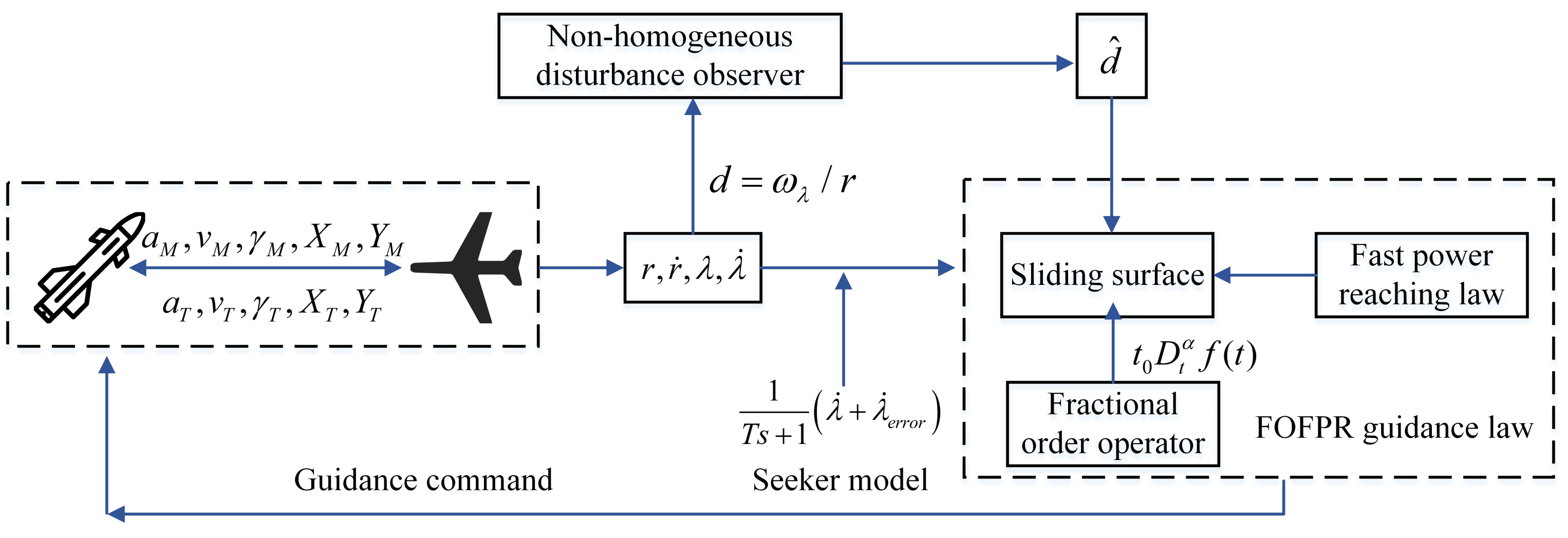
In this section, numerical simulations are performed to evaluate the performance of the proposed FOFPR guidance law (29) in two cases where the hypersonic vehicle adopts bang-bang and sinusoidal maneuver modes, respectively. The simulation block diagram of the proposed FOFPR guidance law is shown in Figure 2. For the two simulation cases, if not specifically given, the initial conditions of the missile and hypersonic are set as Table 1. The missile mass m = 734 kg. The reference area S r e f = 0.146 m 2 . The atmospheric density ρ ¯ = 1.205 kg/m 2 . The gravity coefficient g = 9.81 m/s 2 . The upper bound of the missile acceleration is considered as a M , m a x = 10 g. The drag coefficient C D can be interpolated based on Table 2 and the parameters of the non-homogeneous disturbance observer (21) are shown in Table 3. Moreover, the parameters of the seeker and actuator are chosen as T = 0.025 s, λ ˙ e r r o r = 0 . 015 and τ = 0.25 s.
Moreover, in order to vertify the superiority of the FOFPR, we design an integer-order fast power reaching (IOFPR) guidance law based on an integer-order sliding surface (44) and the reaching law in Equation (27). Comparative numerical simulations are conducted among the PN, IOFPR and FOFPR guidance laws, respectively. The parameters related to the three guidance laws in the Equations (29), (45) and (46) are shown in Table 4. In all simulations, the fractional-order operator is approximated with high-order integer transfer functions based on Ref. [35]. According to Ref. [36], the energy consumption J consumed by the missile in the interception process is defined as Equation (47).
s = c 0 t λ ˙ d t + λ ˙
a M , P N G = N | r ˙ | λ ˙
a M , I O F P R = ρ 1 | s | β sign ( s ) ρ 2 s f ( x , t ) d ^ ( t ) c λ ˙ g ( x , t )
J = 0 t f a M 2 d t

4.1. Hypersonic Vehicle Adopts the Bang-Bang Maneuver Mode

In this subsection, the simulation analysis is performed, with the hypersonic vehicle adopting the bang-bang maneuver mode. The acceleration of the hypersonic vehicle changes, as shown in Equation (48). The simulation results are presented in Table 5 and Figure 3.
a T = 0 , if t 2 s 2 g , if t > 2 s
It can be seen from Table 5 that the missile can successfully intercept the hypersonic vehicle under the action of three guidance laws, respectively, and that there is not a significant difference in the interception time. However, the FOFPR has great advantages in its interception accuracy and energy consumption. Compared with the PN, the FOFPR improves the guidance accuracy by 86.21 % and consumes 4.7016 × 10 4 less energy. In comparison to the IOFPR, the FOFPR promotes the guidance accuracy by 81.95 % and consumes 2.1685 × 10 4 less energy. As shown in Figure 3a, when the missile is guided by the FOFPR and IOFPR guidance laws, the interception trajectories are more straight than that of the PN, and the ballistic curvature is smoother. In Figure 3b, under the action of the PN, the LOS angular rate decreases with the interception time and does not converge strictly to zero. Nevertheless, for the IOFPR and FOFPR guidance laws, the LOS angular rate can converge to the neighbor of zero, and the FOFPR shows a greater performance in the convergence speed and accuracy than that of the IOFPR. It can be observed from Figure 3c that, compared to the PN and IOFPR guidance laws, when the hypersonic vehicle adopts the bang-bang maneuver mode, the acceleration command does not exceed the maximum limit a M , m a x = 10 g and changes smoothly under the action of the FOFPR. In Figure 3d, the two designed sliding surfaces can converge to zero without a chattering phenomenon in the process of convergence. However, when the missile is guided by the FOFPR, the convergence speed and accuracy of the sliding surface are better than those of the IOFPR. It can be observed from Figure 3e that the missile speed gradually decreases due to the aerodynamic drag, and that the speed at the final interception moment is approximately 851 m/s. As shown in Figure 3f, the designed non-homogeneous observer can effectively estimate the maneuvering information of the hypersonic vehicle accurately.

4.2. Hypersonic Vehicle Adopts the Sinusoidal Maneuver Mode

In this subsection, a simulation analysis is conducted, with the hypersonic vehicle adopting the sinusoidal maneuver mode. The acceleration of the hypersonic vehicle changes, as shown in Equation (49). The simulation results are presented in Table 6 and Figure 4.
a T = 4 g sin π 5 t + π 3
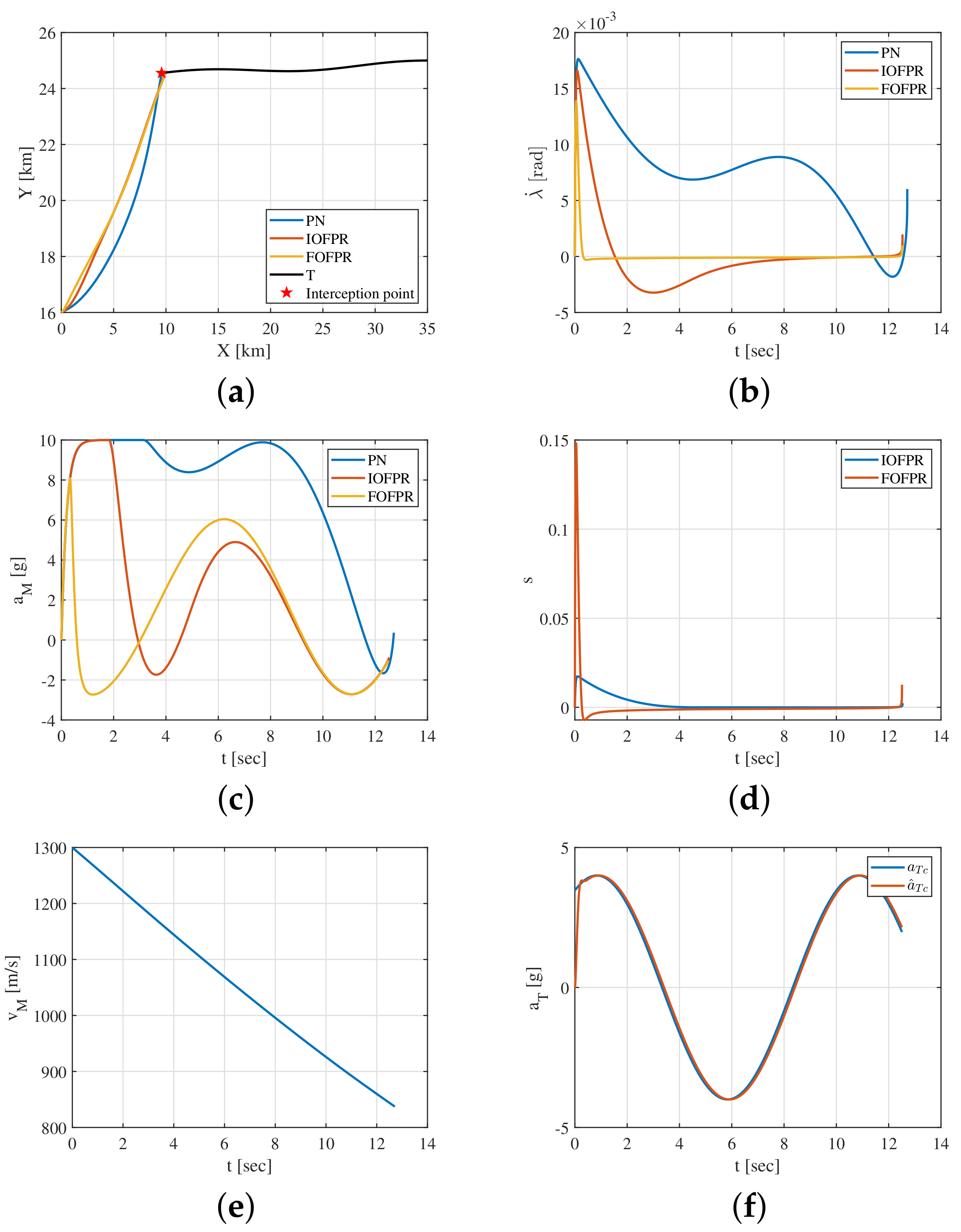
As shown in Table 6, when the hypersonic vehicle adopts the sinusoidal maneuver mode, the missile can successfully intercept the hypersonic vehicle under the action of the three guidance laws, and the interception time is basically the same. However, the value of the miss distance and energy consumption are the largest for the PN, which is not acceptable and is ineffective in the application of actual interception scenarios. Compared with the PN, the FOFPR improves the guidance accuracy by 59.81 % and consumes 6.8872 × 10 4 less energy. In comparison to the IOFPR, the FOFPR promotes the guidance accuracy by 41.89 % and consumes 1.0834 × 10 4 less energy. It can be observed from Figure 4a that, under the action of the three guidance laws, the missile can move towards the hypersonic vehicle, and that the ballistic trajectory is the straightest based on the FOFPR. In Figure 4b, when guided by the PN, the LOS angular rate does not converge to around zero effectively and tends to disperse. Nevertheless, based on the IOFPR and FOFPR guidance laws, the LOS angular rate has always been stable around zero, and the convergence speed and accuracy of the FOFPR are better than those of the IOFPR. It effectively satisfies the guidance objectives. It can be observed from Figure 4c that, compared with the PN and IOFPR guidance laws, the acceleration command does not exceed the maximum limit a M , m a x = 10 g and changes smoothly under the action of the FOFPR. As shown in Figure 4d, under the action of the IOFPR and FOFPR guidance laws, the two sliding surfaces change at the neighbor of zero, and there is no chattering phenomenon in the process of convergence. However, the convergence speed and accuracy of the FOFPR are better than those of the IOFPR. It can be observed form Figure 4e that the missile speed gradually decreases due to the aerodynamic drag, and that the speed at the final interception moment is approximately 837 m/s. As shown in Figure 4f, the disturbance observer enables the quick and precise tracking of the maneuver information of the hypersonic vehicle, which ensures the efficient implementation of the interception mission.

5. Conclusions and Future Discussion

In view of the problem of a low-speed missile intercepting hypersonic vehicles, a fractional-order fast power reaching (FOFPR) guidance scheme is proposed by introducing the fractional-order operator into the sliding surface. Comparative numerical simulations are performed with the proportional navigation (PN) and the integral-order fast power reaching (IOFPR) guidance laws with different maneuver modes of the hypersonic vehicle. The main conclusions can be drawn as follows:
  • The FOFPR guidance law can accurately and effectively intercept the hypersonic vehicle with different maneuver modes, and the guidance command changes reasonably and smoothly without a chattering phenomenon;
  • When the hypersonic vehicle adopts the bang-bang maneuver mode, under the action of the FOFPR, the interception accuracy is improved by 86.21 % and 81.195 % and consumes 4.7016 × 10 4 and 2.1685 × 10 4 less energy compared to the PN and IOFPR guidance laws, respectively;
  • When the hypersonic vehicle adopts the sinusoidal maneuver mode, under the action of the FOFPR, the interception accuracy is improved by 59.81 % and 41.89 % and consumes 6.8872 × 10 4 and 1.0834 × 10 4 less energy compared to the PN and IOFPR guidance laws, respectively.
The design of the fractional-order guidance law for intercepting the hypersonic vehicles in the three-dimensional plane is our future work.

Author Contributions

The contributions of the authors are the following, conceptualization: all authors; methodology: X.Z. and W.L.; software: S.L.; writing: S.L.; investigation: W.L.; funding acquisition: B.Y. All authors have read and agreed to the published version of the manuscript.

Funding

The authors would like to appreciate the financial support from the National Natural Science Foundation of China (NSFC) (61603297), Natural Science Foundation of Shaanxi Province (2020JQ-219) and Aviation Fund (20200001053005).

Institutional Review Board Statement

Not applicable.

Informed Consent Statement

Not applicable.

Data Availability Statement

All data used during the study appear in the submitted article.

Conflicts of Interest

All of the authors declare that they have no known competing financial interests or personal relationships that could appear to influence the work reported in this paper.

References

  1. Xu, B.; Shi, Z. An overview on flight dynamics and control approaches for hypersonic vehicles. Sci. China Inf. Sci. 2015, 58, 1–19. [Google Scholar] [CrossRef]
  2. Liu, S.; Yan, B.; Liu, R.; Dai, P.; Yan, J.; Xin, G. Cooperative guidance law for intercepting a hypersonic target with impact angle constraint. AERONAUT J. 2022, 1–19. [Google Scholar] [CrossRef]
  3. Zhang, T.T.; Wang, Z.G.; Huang, W.; Li, S.B. A design approach of wide-speed-range vehicles based on the cone-derived theory. Aerosp. Sci. Technol. 2017, 71, 42–51. [Google Scholar] [CrossRef]
  4. Shen, Y.; Huang, W.; Zhang, T.T.; Yan, L. Parametric modeling and aerodynamic optimization of EXPERT configuration at hypersonic speeds. Aerosp. Sci. Technol. 2019, 84, 641–649. [Google Scholar] [CrossRef]
  5. Becker, K. Closed-form solution of pure proportional navigation. IEEE Trans. Aerosp. Electron. Syst. 1990, 26, 526–533. [Google Scholar] [CrossRef]
  6. Shukla, U.S.; Mahapatra, P.R. The proportional navigation dilemma-pure or true? IEEE Trans. Aerosp. Electron. Syst. 1990, 26, 382–392. [Google Scholar] [CrossRef]
  7. Zhao, B.; Dong, X.; Li, Q.; Ren, Z. A Combined Guidance Law for Intercepting Hypersonic Large Maneuvering Targets. In Proceedings of the IEEE 2020 Chinese Automation Congress (CAC), Shanghai, China, 6–8 November 2020; pp. 1425–1430. [Google Scholar]
  8. Kumar, A.; Ojha, A.; Padhy, P.K. Anticipated trajectory based proportional navigation guidance scheme for intercepting high maneuvering targets. Int. J. Control. Autom. Syst. 2017, 15, 1351–1361. [Google Scholar] [CrossRef]
  9. Yan, B.; Dai, P.; Liu, R.; Xing, M.; Liu, S. Adaptive super-twisting sliding mode control of variable sweep morphing aircraft. Aerosp. Sci. Technol. 2019, 92, 198–210. [Google Scholar] [CrossRef]
  10. Liu, S.; Liu, W.; Yan, B.; Liu, S.; Yin, Y. Impact Time Control Guidance Law for Large Initial Lead Angles Based on Sliding Mode Control. In Journal of Physics: Conference Series; IOP Publishing: Bristol, UK, 2021; Volume 2031, p. 012050. [Google Scholar]
  11. Babaei, A.R.; Malekzadeh, M.; Madhkhan, D. Adaptive super-twisting sliding mode control of 6-DOF nonlinear and uncertain air vehicle. Aerosp. Sci. Technol. 2019, 84, 361–374. [Google Scholar] [CrossRef]
  12. Kada, B. A new methodology to design sliding-pid controllers: Application to missile flight control system. IFAC Proc. Vol. 2012, 45, 673–678. [Google Scholar] [CrossRef] [Green Version]
  13. Shtessel, Y.B.; Tournes, C.H. Integrated higher-order sliding mode guidance and autopilot for dual control missiles. J. Guid. Control Dyn. 2009, 32, 79–94. [Google Scholar] [CrossRef]
  14. Idan, M.; Shima, T.; Golan, O.M. Integrated sliding mode autopilot-guidance for dual-control missiles. J. Guid. Control Dyn. 2007, 30, 1081–1089. [Google Scholar] [CrossRef]
  15. Chen, F.; He, G.; He, Q. A finite-time-convergent composite guidance law with strong fault-tolerant performance. Proc. Inst. Mech. Eng. Part G J. Aerosp. Eng. 2019, 233, 3120–3130. [Google Scholar] [CrossRef]
  16. Liu, S.; Yan, B.; Zhang, T.; Dai, P.; Yan, J. Guidance Law with Desired Impact Time and FOV Constrained for Antiship Missiles Based on Equivalent Sliding Mode Control. Int. J. Aerosp. Eng. 2021, 2021, 9923332. [Google Scholar] [CrossRef]
  17. Zhang, K.; Yang, S. Fast Convergent Nonsingular Terminal Sliding Mode Guidance Law with Impact Angle Constraint. In Proceedings of the IEEE 2018 37th Chinese Control Conference (CCC), Wuhan, China, 25–27 July 2018; pp. 2963–2968. [Google Scholar]
  18. Wang, X.; Qiu, X. Study on Fuzzy Neural Sliding Mode Guidance Law with Terminal Angle Constraint for Maneuvering Target. Math. Probl. Eng. 2020, 2020, 4597937. [Google Scholar] [CrossRef]
  19. Zhu, C.; Guo, Z. Design of head-pursuit guidance law based on backstepping sliding mode control. Int. J. Aerosp. Eng. 2019, 2019, 8214042. [Google Scholar] [CrossRef]
  20. Monje, C.A.; Chen, Y.; Vinagre, B.M.; Xue, D.; Feliu-Batlle, V. Fractional-Order Systems and Controls: Fundamentals and Applications; Springer Science & Business Media: Berlin/Heidelberg, Germany, 2010. [Google Scholar]
  21. Zhou, X.; Li, X. Trajectory tracking control for electro-optical tracking system based on fractional-order sliding mode controller with super-twisting extended state observer. ISA Trans. 2021, 117, 85–95. [Google Scholar] [CrossRef]
  22. Aboelela, M.A.; Ahmed, M.F.; Dorrah, H.T. Design of aerospace control systems using fractional PID controller. J. Adv. Res. 2012, 3, 225–232. [Google Scholar] [CrossRef] [Green Version]
  23. Ahmed, M.F.; Dorrah, H.T. Design of gain schedule fractional PID control for nonlinear thrust vector control missile with uncertainty. Automatika 2018, 59, 357–372. [Google Scholar] [CrossRef]
  24. Sheng, Y.; Zhang, Z.; Xia, L. Fractional-order sliding mode control based guidance law with impact angle constraint. Nonlinear Dyn. 2021, 106, 425–444. [Google Scholar] [CrossRef]
  25. Zhou, X.; Wang, W.; Liu, Z.; Liang, C.; Lai, C. Impact angle constrained three-dimensional integrated guidance and control based on fractional integral terminal sliding mode control. IEEE Access 2019, 7, 126857–126870. [Google Scholar] [CrossRef]
  26. Golestani, M.; Ahmadi, P.; Fakharian, A. Fractional order sliding mode guidance law: Improving performance and robustness. In Proceedings of the IEEE 2016 4th International Conference on Control, Instrumentation, and Automation (ICCIA), Qazvin, Iran, 27–28 January 2016; pp. 469–474. [Google Scholar]
  27. Eray, O.; Tokat, S. The design of a fractional-order sliding mode controller with a time-varying sliding surface. Trans. Inst. Meas. Control 2020, 42, 3196–3215. [Google Scholar] [CrossRef]
  28. Zhang, S.; Li, Z.; Wang, H.N.; Xiong, T. Fractional order sliding mode control based on single parameter adaptive law for nano-positioning of piezoelectric actuators. IET Control Theory Appl. 2021, 15, 1422–1437. [Google Scholar] [CrossRef]
  29. Podlubny, I. Fractional Differential Equations: An Introduction to Fractional Derivatives, Fractional Differential Equations, to Methods of Their Solution and Some of Their Applications; Elsevier: Amsterdam, The Netherlands, 1998. [Google Scholar]
  30. Levant, A. Non-homogeneous finite-time-convergent differentiator. In Proceedings of the 48h IEEE Conference on Decision and Control (CDC) Held Jointly with 2009 28th Chinese Control Conference, Shanghai, China, 15–18 December 2009; pp. 8399–8404. [Google Scholar]
  31. Deng, W.; Li, C.; Lü, J. Stability analysis of linear fractional differential system with multiple time delays. Nonlinear Dyn. 2007, 48, 409–416. [Google Scholar] [CrossRef]
  32. Tokat, S.; Fadali, M.S.; Eray, O. A classification and overview of sliding mode controller sliding surface design methods. In Recent Advances in Sliding Modes: From Control to Intelligent Mechatronics; Springer: Berlin/Heidelberg, Germany, 2015; pp. 417–439. [Google Scholar]
  33. Qian, D.; Yi, J. Hierarchical Sliding Mode Control for Under-Actuated Cranes; Springer: Berlin/Heidelberg, Germany, 2016. [Google Scholar]
  34. Xia, Y.; Fu, M. Compound Control Methodology for Flight Vehicles; Springer: Berlin/Heidelberg, Germany, 2013; Volume 438. [Google Scholar]
  35. Valerio, D.; Da Costa, J.S. Ninteger: A non-integer control toolbox for MatLab. In Proceedings of the Fractional Differentiation and Its Applications, Bordeaux, France, 19–21 July 2004. [Google Scholar]
  36. Fang, F.; Cai, Y.L. Optimal cooperative guidance with guaranteed miss distance in three-body engagement. Proc. Inst. Mech. Eng. Part G J. Aerosp. Eng. 2018, 232, 492–504. [Google Scholar] [CrossRef]
Figure 1. Guidance geometry of missile–hypersonic-vehicle engagement.
Aerospace 09 00053 g001
Figure 2. Simulation block diagram of FOFPR guidance law.
Aerospace 09 00053 g002
Figure 3. Interception results of the bang-bang maneuver mode. (a) Trajectory; (b) LOS angular rate; (c) acceleration command; (d) sliding surface; (e) speed; (f) acceleration command of the hypersonic vehicle.
Aerospace 09 00053 g003
Figure 4. Interception results of the sinusoidal maneuver mode. (a) Trajectory; (b) LOS angular rate; (c) acceleration command; (d) sliding surface; (e) speed; (f) acceleration command of the hypersonic vehicle.
Aerospace 09 00053 g004
Table 1. Initial condition of the missile and the hypersonic vehicle.
Position km Speed m / s Path Angle
T 35 , 20 2000180
M 0 , 16 13008
Table 2. Drag coefficient.
Mach Number0.20.780.941.071.321.612.433.5
C D 0.2410.2130.2580.4070.4450.3720.2550.190
Table 3. Parameters of the non-homogeneous disturbance observer.
L ζ 0 ζ 1 ζ 2 μ 0 μ 1 μ 2
0.11.11.52368
Table 4. Parameters of the guidance law.
TypeParameter Values
PN N = 4
IOFPR c = 0.4
FOFPR k 1 = 6.5 , k 2 = 1.5 , α 1 = 0.9 , α 2 = 0.1
Reaching law ρ 1 = 0.1 , ρ 2 = 0.06 , β = 0.6
Table 5. Analysis of the bang-bang maneuver mode.
Guidance LawInterception Time s Miss Distance m Energy m 2 / s 3
PN12.4241.744.9944  × 10 4
IOFPR12.3581.332.4613  × 10 4
FOFPR12.3340.242.9275  × 10 3
Table 6. Analysis of the sinusoidal maneuver mode.
Guidance LawInterception Time s Miss Distance m Energy m 2 / s 3
PN12.7132.148.3284  × 10 4
IOFPR12.5301.482.5246  × 10 4
FOFPR12.5100.861.4412  × 10 4
Publisher’s Note: MDPI stays neutral with regard to jurisdictional claims in published maps and institutional affiliations.