
Numerical Investigation and Parameter Sensitivity Analysis on Flow and Heat Transfer Performance of Jet Array Impingement Cooling in a Quasi-Leading-Edge Channel


Abstract
:1. Introduction
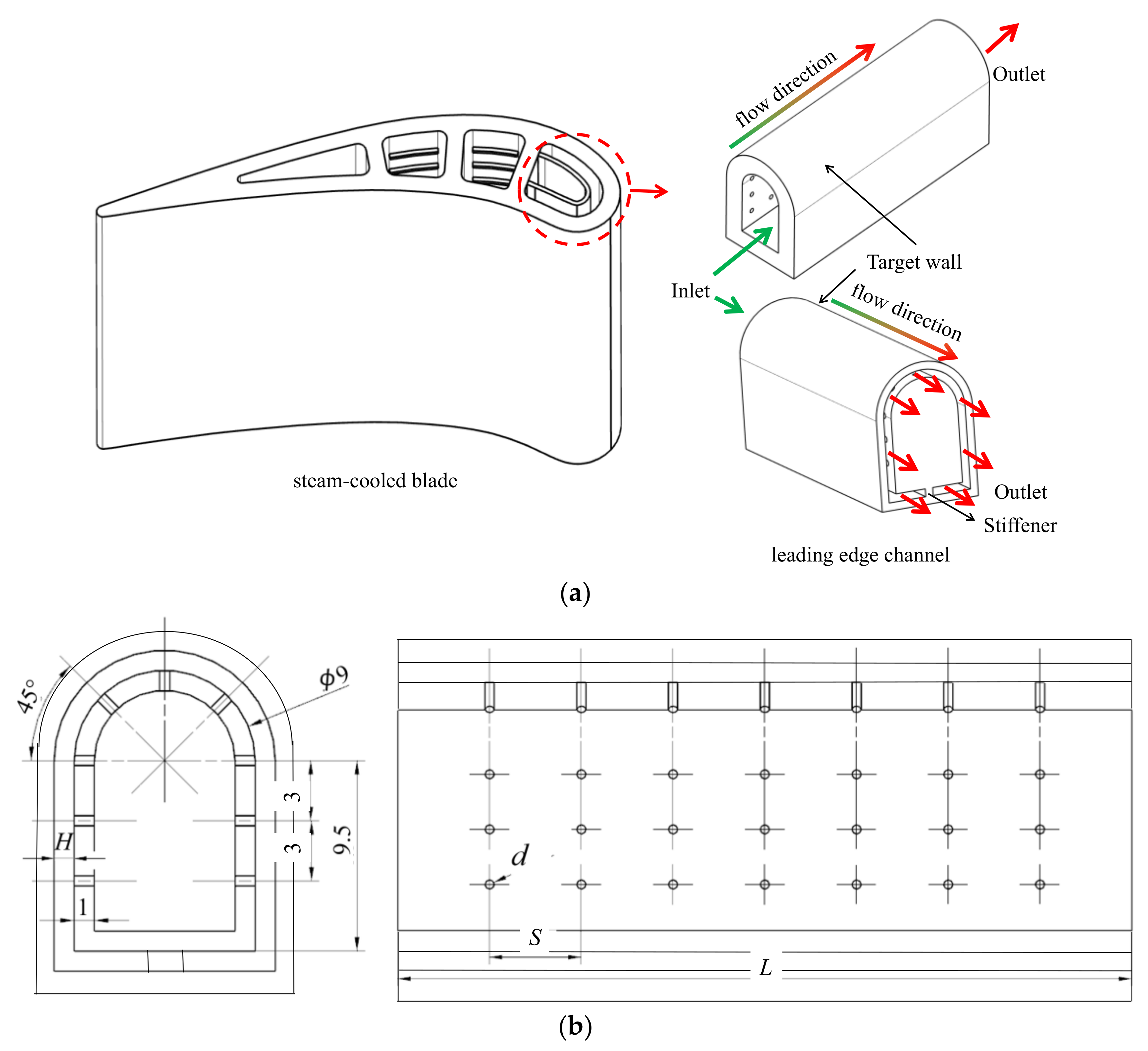
2. Research Object
2.1. Physical Model
2.2. Data Reduction
3. Numerical Methods
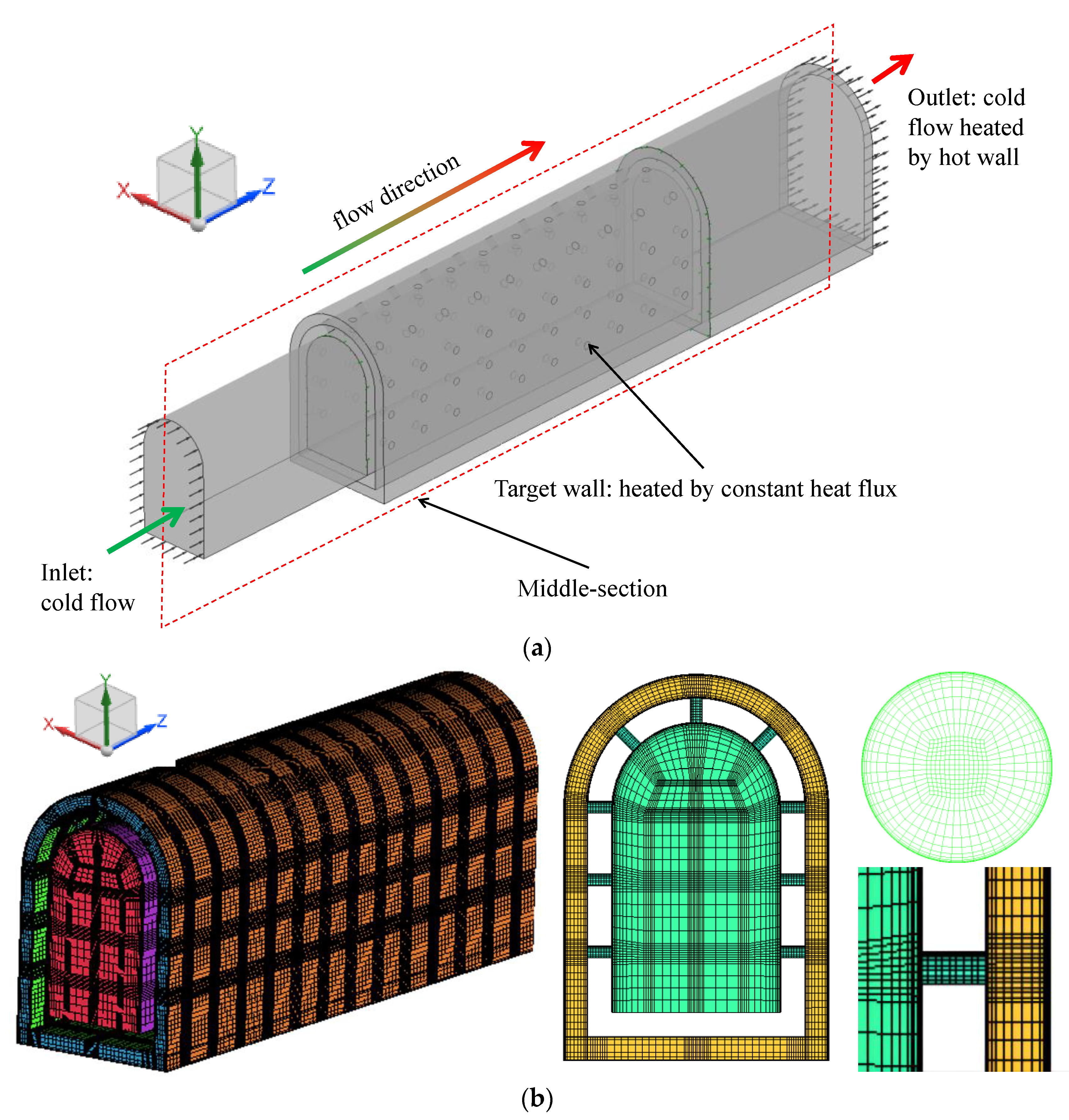
3.1. Numerical Model
3.2. Numerical Calculation Method
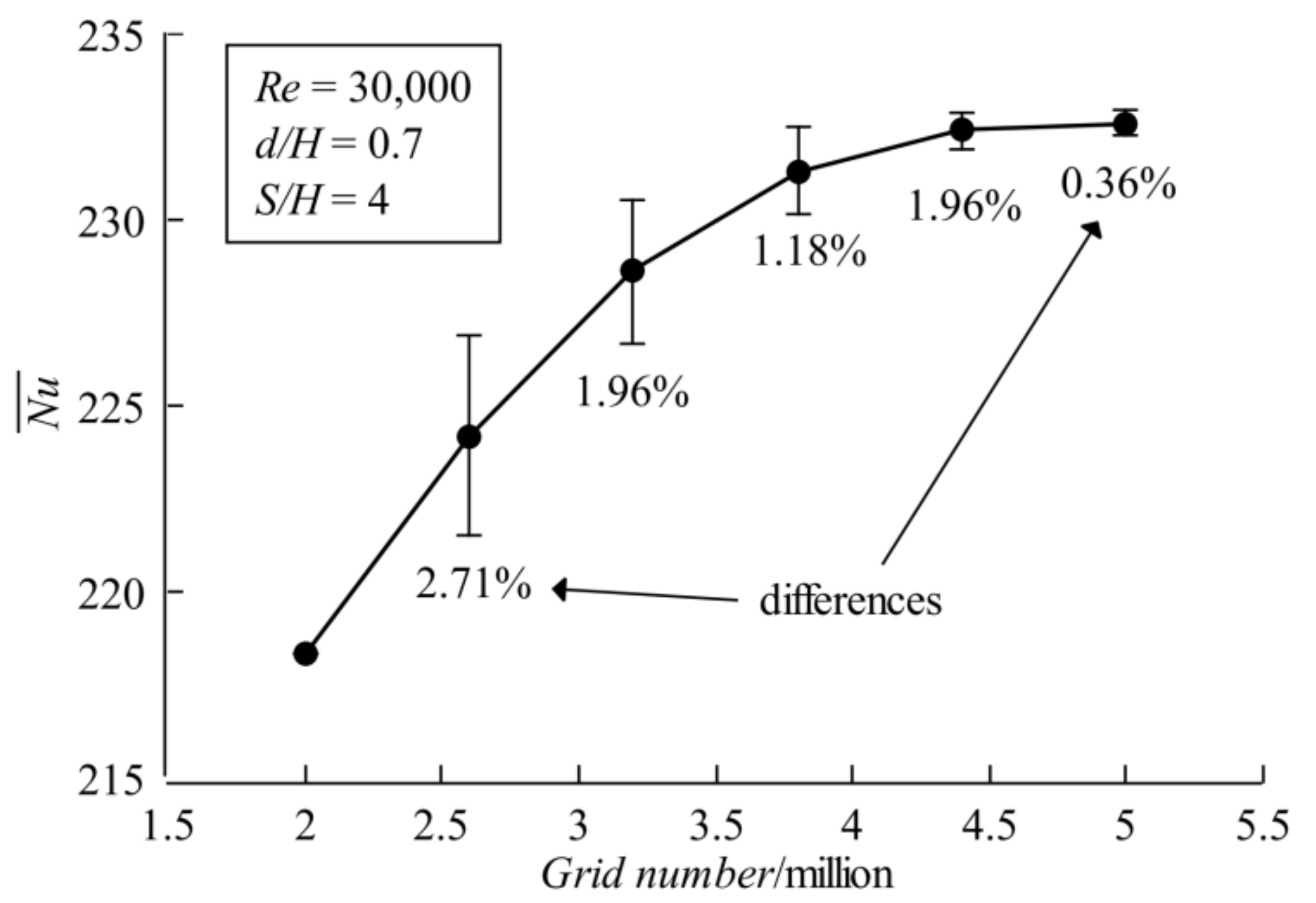
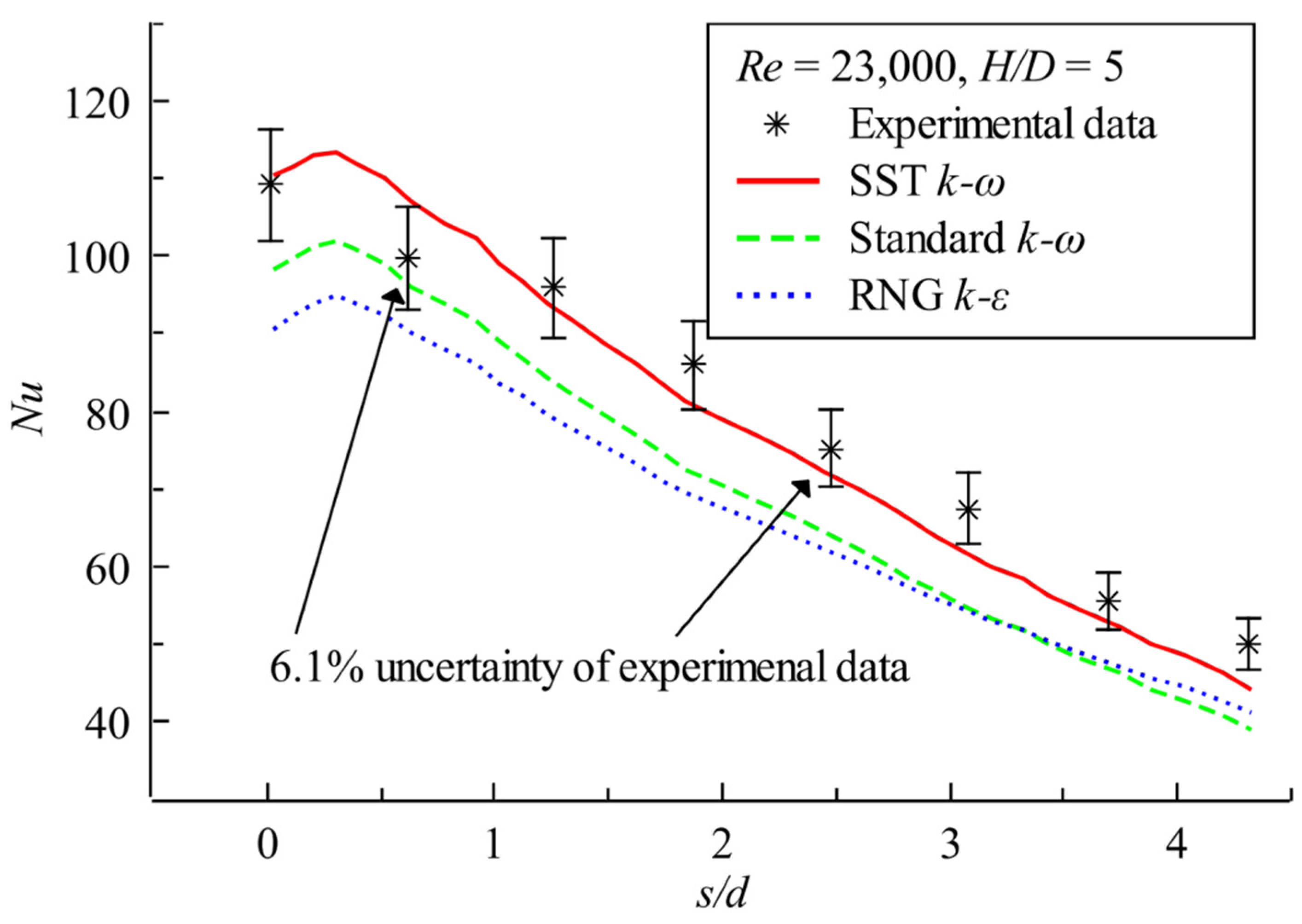
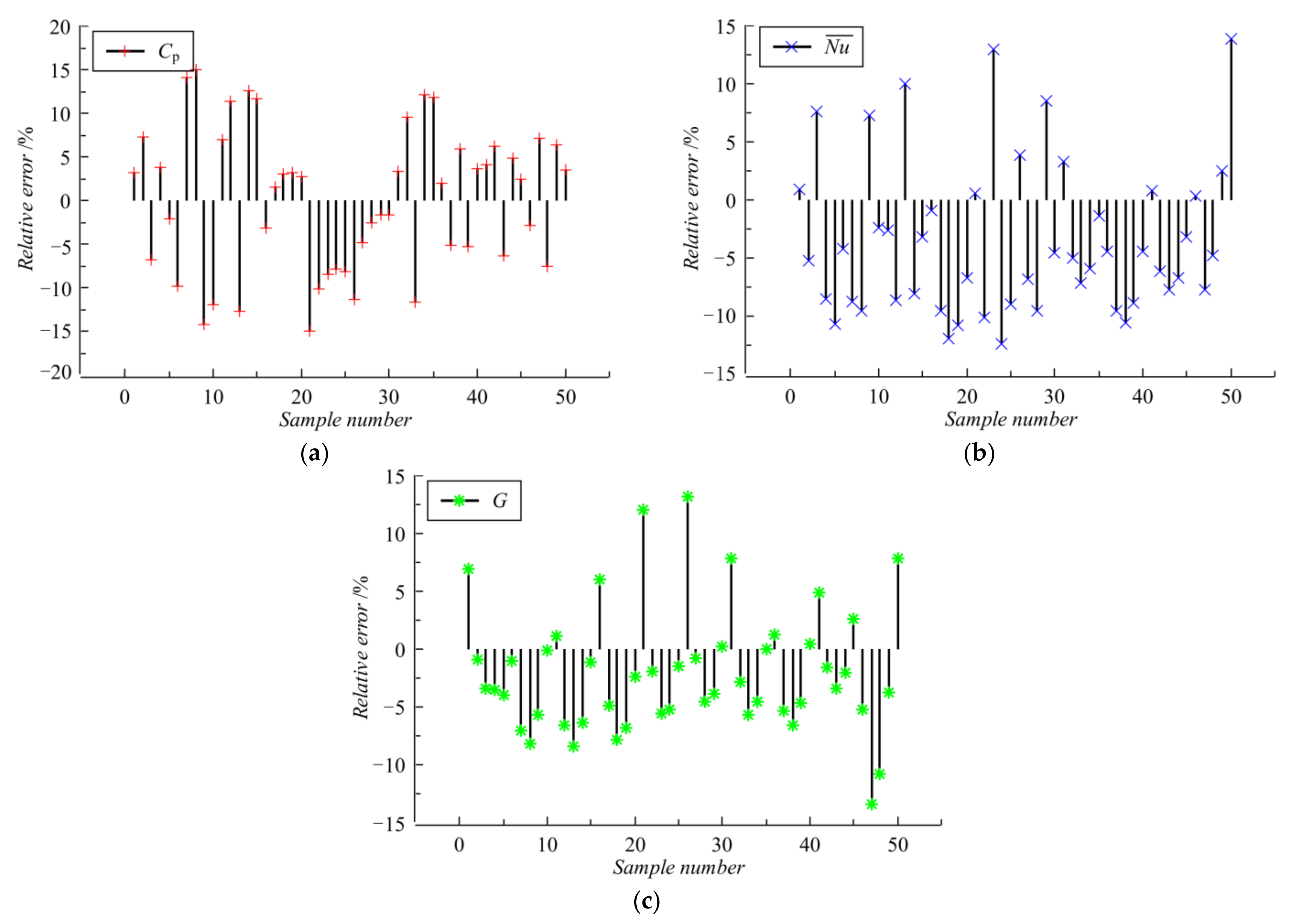
3.3. Verification of Numerical Method
4. Results Analysis and Discussion
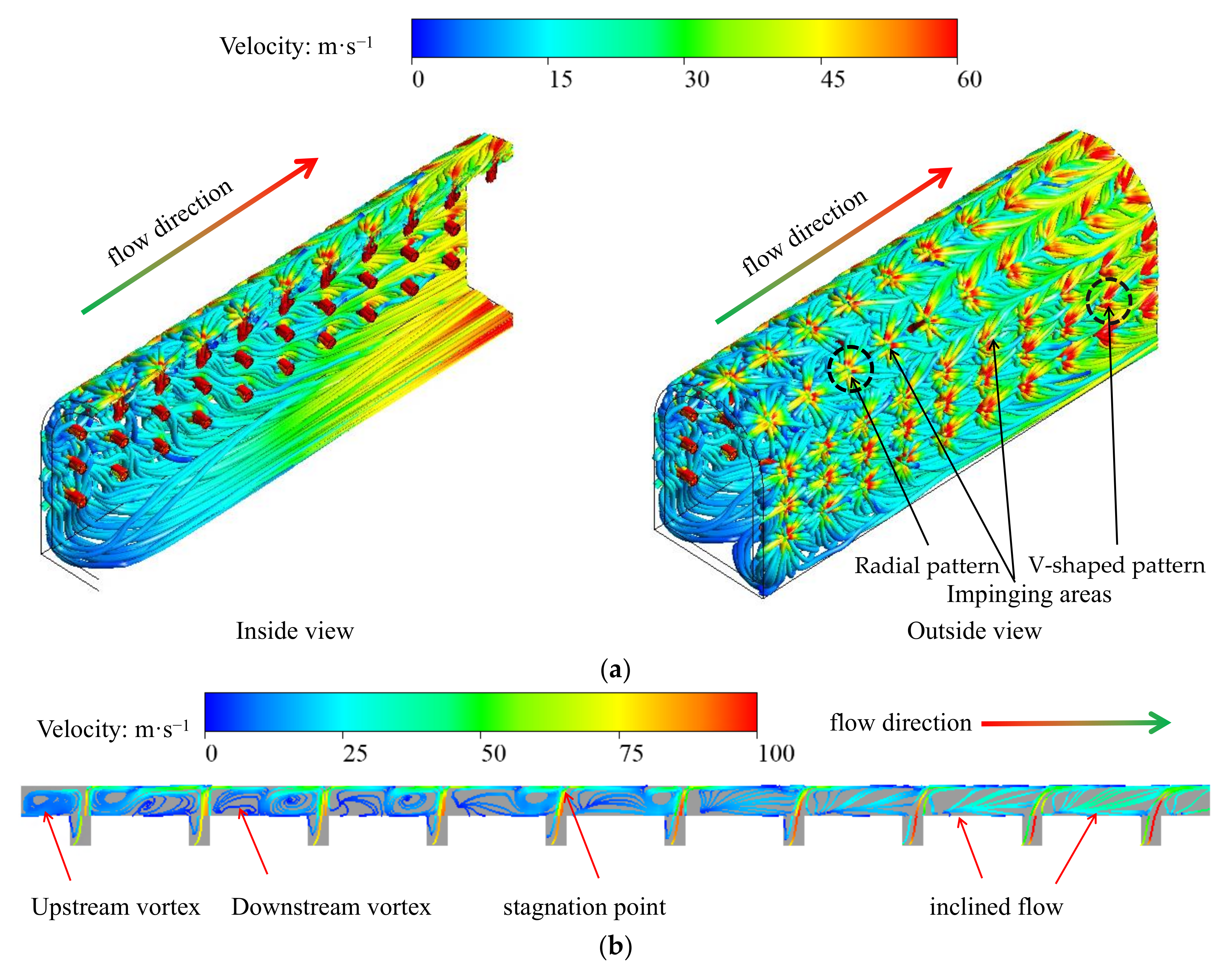
4.1. Flow and Heat Transfer Characteristics
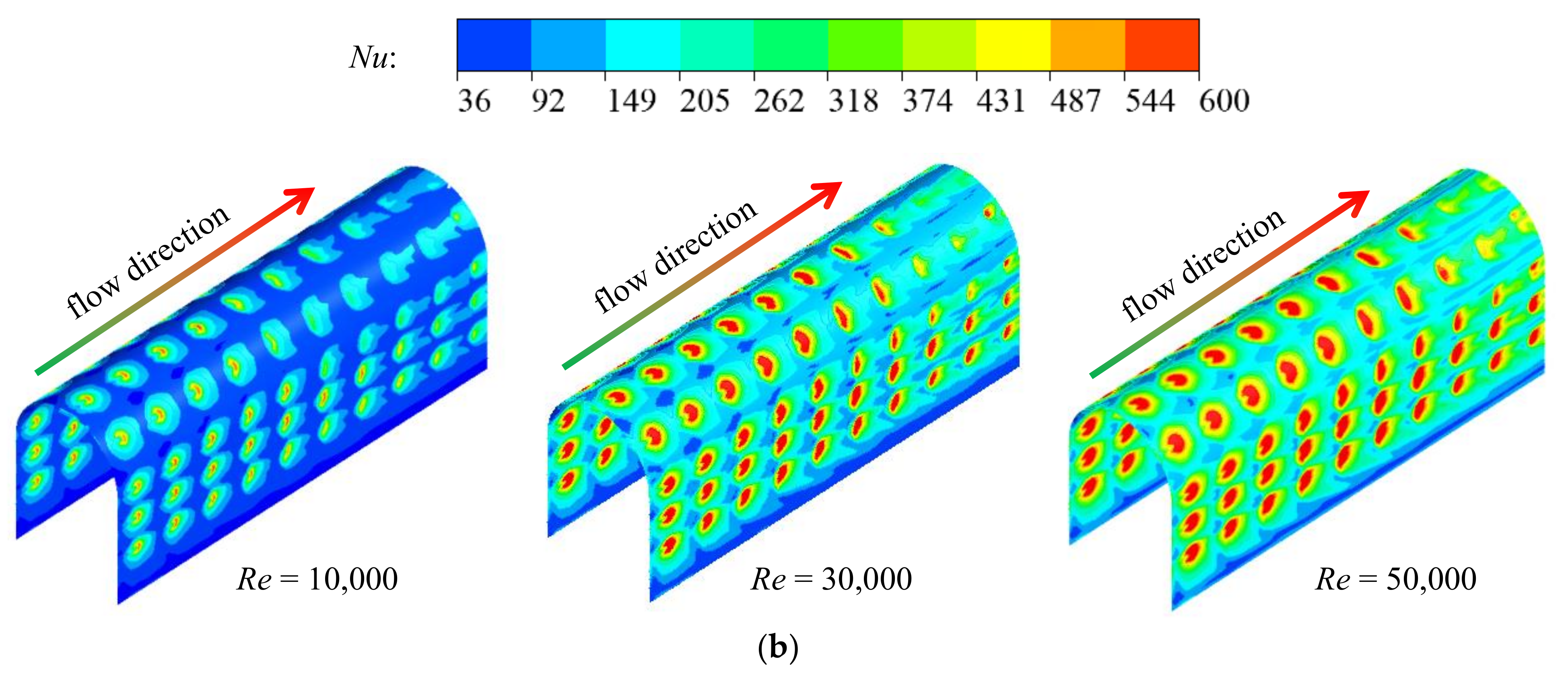
4.2. Effect of Reynolds Number
4.3. Effect of Jet Hole Diameter
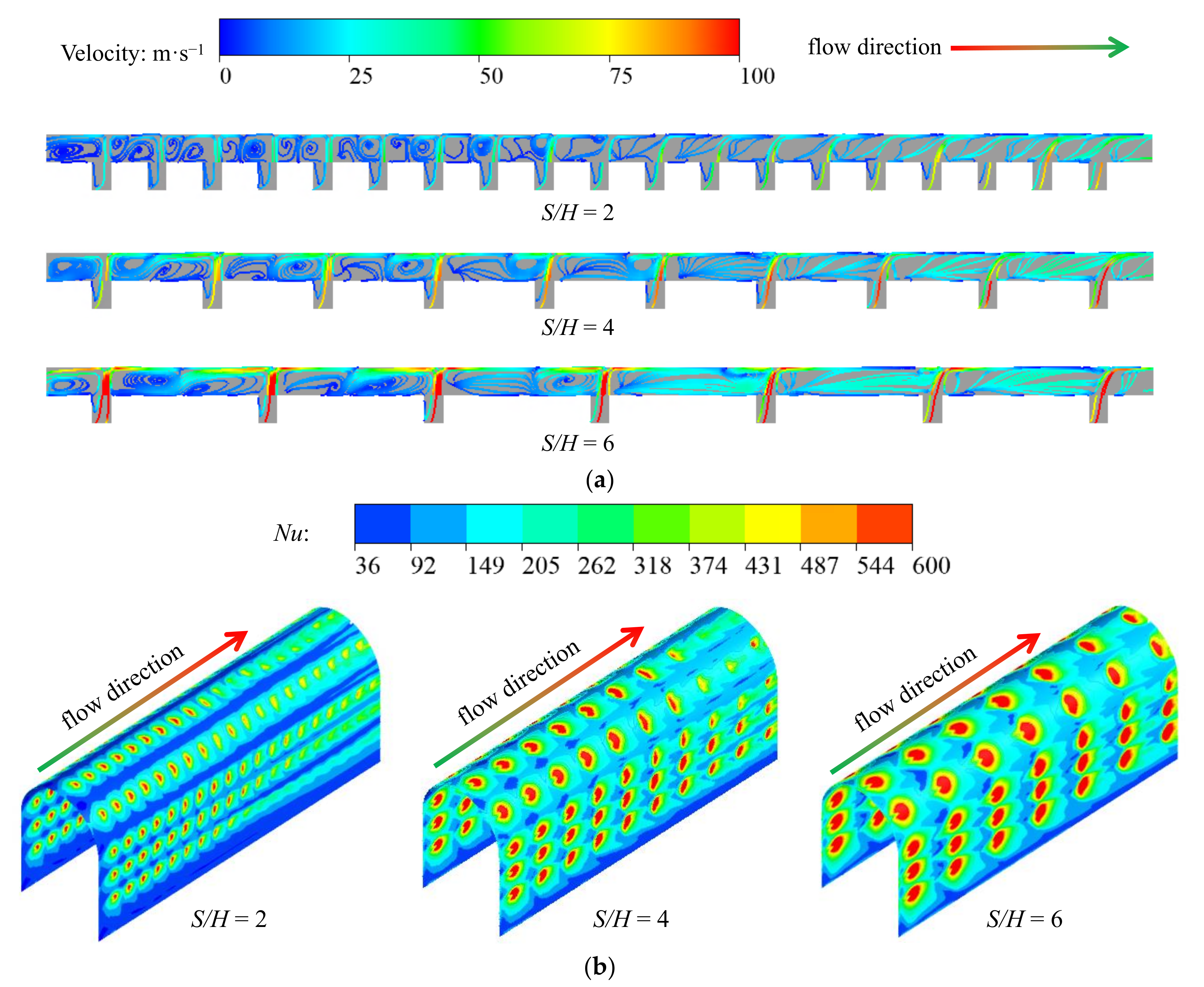
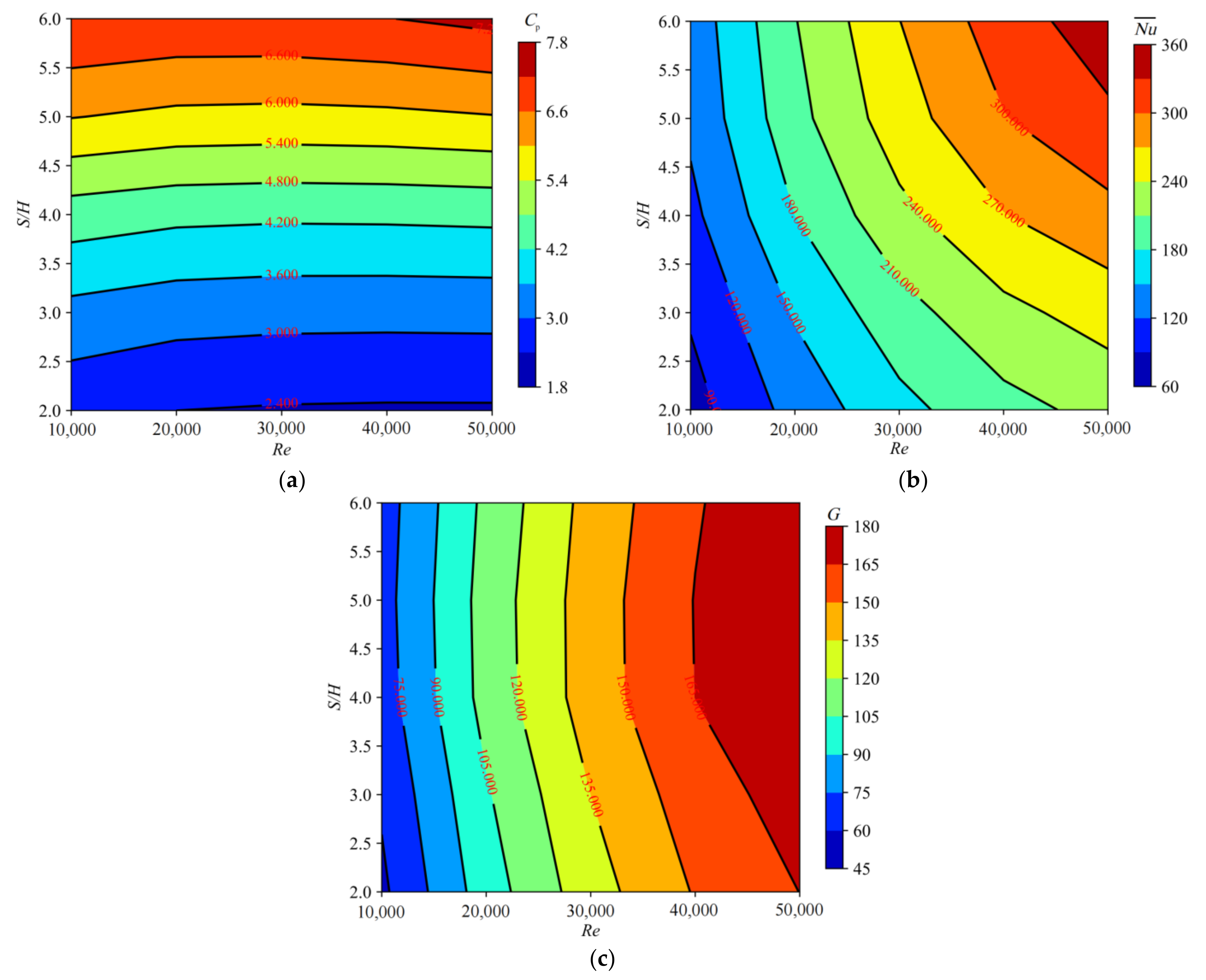
4.4. Effect of Jet Hole Spacing
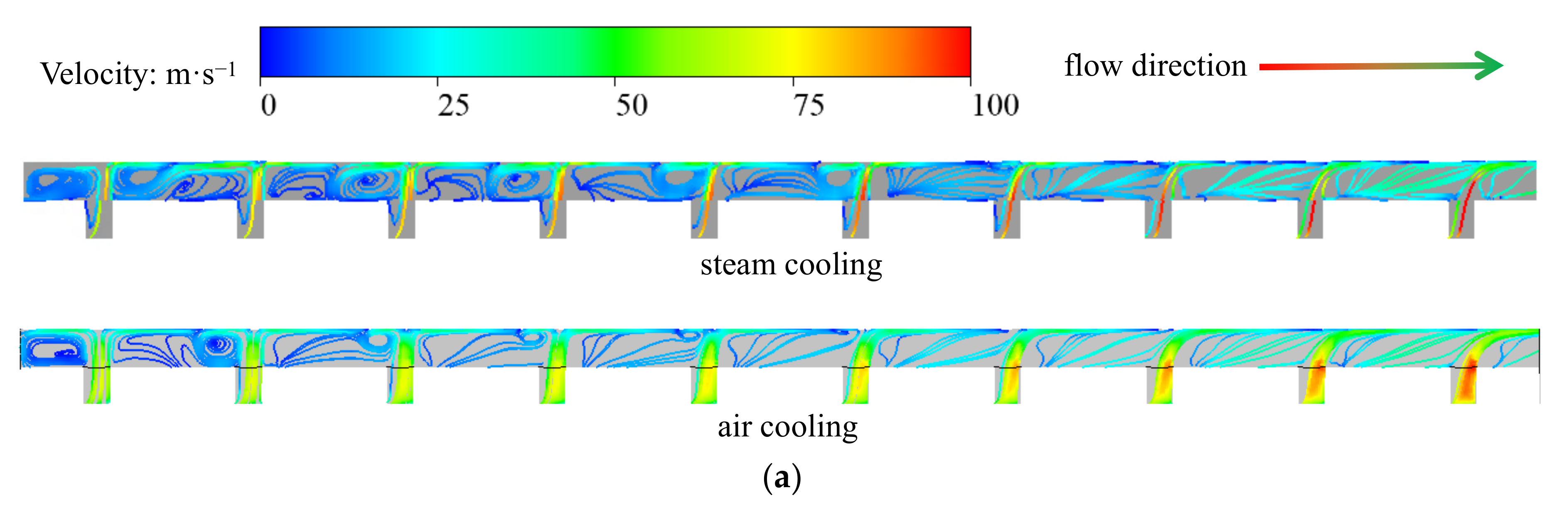
4.5. Comparison of Steam Cooling and Air Cooling
4.6. Correlation Fitting
4.7. Parameter Sensitivity Analysis
5. Conclusions
- (1)
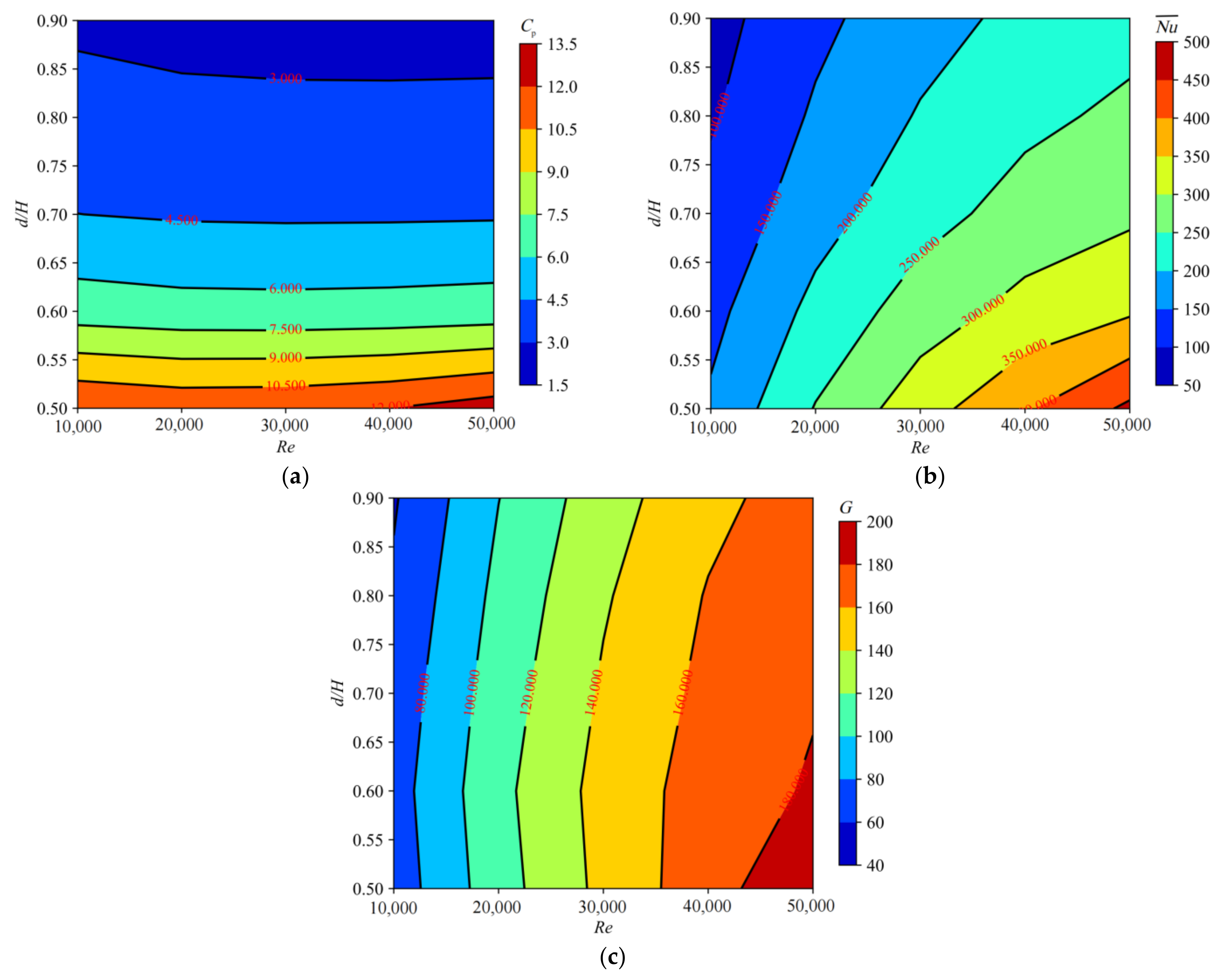
- The change in Re has relatively little effect on the pressure loss coefficient of jet array impingement cooling in the quasi-leading-edge channel. When Re increases from 10,000 to 60,000 under different d/H and S/H, the average Nusselt number of the quasi-leading-edge channel increases by 1.59 to 1.91 times and the comprehensive thermal coefficient of the quasi-leading-edge channel increases by 1.62 to 1.86 times.
- (2)
- When the d/H changes from 0.5 to 0.9 at different Re, the pressure loss coefficient in the quasi-leading-edge channel decreases by 76% to 79% and the average Nusselt number of the target wall decreases by about 45% to 49%. When the S/H increases from 2 to 6 at different Re, the pressure loss coefficient in the channel increases by about 1.64 to 1.92 times and the average Nusselt number of the target wall increases by 54% to 64%.
- (3)
- The pressure loss coefficient in the quasi-leading-edge channel can be reduced by increasing the jet hole diameter and reducing the jet hole spacing. The heat transfer effect of the target wall can be improved by reducing the jet hole diameter and increasing the jet hole spacing. The comprehensive thermodynamic coefficient reaches its maximum values at d/H = 0.6 for lower Reynolds numbers and at S/H = 5 for higher Reynolds numbers.
- (4)
- The pressure loss coefficient in the quasi-leading-edge channel for steam cooling is slightly less than that for air cooling. The average Nusselt numbers and comprehensive thermal coefficients of the quasi-leading-edge channel for steam cooling are 17.19% to 36.36% and 18.78% to 38.35% higher than those for air cooling under different Re.
- (5)
- The pressure loss coefficient of the quasi-leading-edge channel is most sensitive to the change in d/H, followed by the changes in S/H and Pr, while it is not sensitive to the change in Re. The average Nusselt number of the quasi-leading-edge channel is most sensitive to the change in Re, followed by the changes in d/H and S/H, and is least sensitive to the change in Pr. The comprehensive thermal coefficient of the channel is most sensitive to the change in Re, followed by the change in Pr, and is least sensitive to the changes in d/H and S/H.
- (6)
- When the heat transfer performance of jet array impingement cooling in the quasi-leading-edge channel is expected to be enhanced, the two parameters of Re and d/H are the most important. When the pressure loss of the quasi-leading-edge channel is expected to be reduced, most attention should be paid to the parameters of d/H and S/H. When the comprehensive thermal performance of the quasi-leading-edge channel is expected to be improved, Re is most important.
Author Contributions
Funding
Institutional Review Board Statement
Informed Consent Statement
Data Availability Statement
Conflicts of Interest
Nomenclature
| Cp | pressure loss coefficient |
| d | diameter of jet hole, mm |
| D | equivalent diameter of the plug-in channel, mm |
| G | comprehensive thermal coefficient |
| H | jet impinging distance, mm |
| L | channel length, mm |
| Nu | local Nusselt number |
| average Nusselt number | |
| Pr | Prandtl number |
| pin | channel inlet pressure, Pa |
| pout | channel outlet pressure, Pa |
| q | wall heat flux, W·m−2 |
| Re | Reynolds number |
| s | circumferential distance, mm |
| S | axial jet hole spacing |
| ST | total sensitivity coefficient |
| Tin | inlet temperature, K |
| Tw | local wall temperature, K |
| u | inlet velocity, m·s−1 |
| Greek symbols | |
| λ | thermal conductivity of the coolant, W·m−1·K−1 |
| ρ | density of the coolant, kg·m−3 |
| v | kinematic viscosity of the coolant, m2·s−1 |
| φ | absolute uncertainty |
| μ | dynamic viscosity, Pa·s |
References
- Xi, L.; Xu, L.; Gao, J.; Zhao, Z.; Li, Y. Cooling performance analysis and structural parameter optimization of X-type truss array channel based on neural networks and genetic algorithm. Int. J. Heat Mass Transf. 2022, 186, 122452. [Google Scholar] [CrossRef]
- Hussain, L.; Khan, M.M.; Masud, M.; Ahmed, F.; Rehman, Z.; Amanowicz, Ł.; Rajski, K. Heat Transfer Augmentation through Different Jet Impingement Techniques: A State-of-the-Art Review. Energies 2021, 14, 6458. [Google Scholar] [CrossRef]
- Ekkad, S.V.; Singh, P. A modern review on jet impingement heat transfer methods. J. Heat Transf. 2021, 143, 064001. [Google Scholar] [CrossRef]
- Bradbury, L.J.S. The structure of a self-preserving turbulent plane jet. J. Fluid Mech. 1965, 23, 31–64. [Google Scholar] [CrossRef]
- Kercher, D.M. Heat transfer by a square array of round air jets impinging perpendicular to a flat surface including the effect of spent air. J. Eng. Gas Turbines Power 1970, 92, 73–82. [Google Scholar] [CrossRef]
- Liu, L.; Zhu, X.; Liu, H.; Du, Z. Effect of tangential jet impingement on blade leading edge impingement heat transfer. Appl. Therm. Eng. 2018, 130, 1380–1390. [Google Scholar] [CrossRef]
- Long, J.; New, T.H. Vortical structures and behaviour of an elliptic jet impinging upon a convex cylinder. Exp. Therm. Fluid Sci. 2019, 100, 292–310. [Google Scholar] [CrossRef]
- Nguyen, D.T.; Maher, B.; Hassan, Y. Effects of nozzle pressure ratio and nozzle-to-plate distance to flowfield characteristics of an under-expanded jet impinging on a flat surface. Aerospace 2019, 6, 4. [Google Scholar] [CrossRef] [Green Version]
- Xu, L.; Yang, T.; Sun, Y.; Xi, L.; Gao, J.; Li, Y. Flow and heat transfer characteristics of a swirling impinging jet issuing from a threaded nozzle of 45 degrees. Energies 2021, 14, 8412. [Google Scholar] [CrossRef]
- Dutta, S.; Singh, P. Opportunities in jet-impingement cooling for gas-turbine engines. Energies 2021, 14, 6587. [Google Scholar] [CrossRef]
- Deng, Q.; Wang, H.; He, W.; Feng, Z. Cooling characteristic of a wall jet for suppressing crossflow effect under conjugate heat transfer condition. Aerospace 2022, 9, 29. [Google Scholar] [CrossRef]
- Yang, X.; Wu, H.; Feng, Z. Jet impingement heat transfer characteristics with variable extended jet holes under strong crossflow conditions. Aerospace 2022, 9, 44. [Google Scholar] [CrossRef]
- Patil, V.S.; Vedula, R.P. Local heat transfer for jet impingement onto a concave surface including injection nozzle length to diameter and curvature ratio effects. Exp. Therm. Fluid Sci. 2018, 92, 375–389. [Google Scholar] [CrossRef]
- Wang, N.; Chen, A.F.; Zhang, M.; Han, J.C. Turbine blade leading edge cooling with one row of normal or tangential impinging jets. J. Heat Transf. 2018, 140, 62201. [Google Scholar] [CrossRef]
- Li, Z.; Liu, J.; Zhou, W.; Liu, Y.; Wen, X. Experimental investigation of flow dynamics of sweeping jets impinging upon confined concave surfaces. Int. J. Heat Mass Transf. 2019, 142, 118457. [Google Scholar] [CrossRef]
- Lyu, Y.; Zhang, J.; Liu, X.; Shan, Y. Experimental study of single-row chevron-jet impingement heat transfer on concave surfaces with different curvatures. Chin. J. Aeronaut. 2019, 32, 2275–2285. [Google Scholar] [CrossRef]
- Lyu, Y.; Zhang, J.; Wang, B.; Tan, X. Convective heat transfer on flat and concave surfaces subjected to an impinging jet form lobed nozzle. Sci. China Technol. Sci. 2020, 63, 116–127. [Google Scholar] [CrossRef]
- Kura, T.; Fornalik-Wajs, E.; Wajs, J.; Kenjeres, S. Curved surface minijet impingement phenomena analysed with ζ-f turbulence model. Energies 2021, 14, 1846. [Google Scholar] [CrossRef]
- Xu, L.; Zhao, X.; Xi, L.; Ma, Y.; Gao, J.; Li, Y. Large-eddy simulation study of flow and heat transfer in swirling and non-swirling impinging jets on a semi-cylinder concave target. Appl. Sci. 2021, 11, 7167. [Google Scholar] [CrossRef]
- Xu, L.; Yun, X.; Xi, L.; Gao, J.; Yang, T.; Li, Y. Heat transfer characteristics of single row of jets issuing from screw-thread nozzles impinging on a concave surface. Case Stud. Therm. Eng. 2021, 28, 101590. [Google Scholar] [CrossRef]
- Qiu, D.; Luo, L.; Zhao, Z.; Wang, S.; Wang, Z.; Sundén, B. On heat transfer and flow characteristics of jets impingement on a concave surface with varying pin-fin arrangements. Int. J. Therm. Sci. 2021, 170, 107163. [Google Scholar] [CrossRef]
- Tepe, A.Ü. Numerical investigation of a novel jet hole design for staggered array jet impingement cooling on a semicircular concave surface. Int. J. Therm. Sci. 2021, 162, 106792. [Google Scholar] [CrossRef]
- Forster, M.; Weigand, B. Experimental and numerical investigation of jet impingement cooling onto a concave leading edge of a generic gas turbine blade. Int. J. Therm. Sci. 2021, 164, 106862. [Google Scholar] [CrossRef]
- Seifi, Z.; Nazari, M.R.; Khalaji, E. 2D numerical simulation of impinging jet onto the concave surface by k-w-v2-f turbulence model. Heat Mass Transf. 2017, 53, 59–72. [Google Scholar] [CrossRef]
- Hadipour, A.; Zargarabadi, M.R. Heat transfer and flow characteristics of impinging jet on a concave surface at small nozzle to surface distances. Appl. Therm. Eng. 2018, 138, 534–541. [Google Scholar] [CrossRef]
- Hadipour, A.; Zargarabadi, M.R.; Mohammadpour, J. Effects of a triangular guide rib on flow and heat transfer in a turbulent jet impingement on an asymmetric concave surface. Phys. Fluids 2020, 32, 075112. [Google Scholar] [CrossRef]
- Ravanji, A.; Zargarabadi, M.R. Effects of elliptical pin-fins on heat transfer characteristics of a single impinging jet on a concave surface. Int. J. Heat Mass Transf. 2020, 152, 119532. [Google Scholar] [CrossRef]
- Huang, H.; Sun, T.; Li, N.; Zhang, G. Sensitization of the modified SST model to the swirling and curvature for turbulent impinging jet heat transfer. Int. J. Heat Mass Transf. 2022, 182, 121980. [Google Scholar] [CrossRef]
- Li, X.; Gaddis, J.L.; Wang, T. Mist/steam heat transfer in confined slot jet impingement. J. Turbomach. 2001, 123, 161–167. [Google Scholar] [CrossRef]
- Wang, T.; Dhanasekaran, T.S. Calibration of a computational model to predict mist/steam impinging jets cooling with an application to gas turbine blades. J. Heat Transf. 2010, 132, 122201. [Google Scholar] [CrossRef]
- Wang, T.; Dhanasekaran, T.S. Model verification of mist/steam cooling with jet impingement onto a concave surface and prediction at elevated operating conditions. J. Turbomach. 2012, 134, 021016. [Google Scholar] [CrossRef]
- Xu, L.; Shuai, Z.; Wang, W.; Gao, J.; Gao, T. Numerical study of on cooling performance for multi-holes steam jet in the internal channel of a hollow turbine blade in international heat transfer conference digital library. In Proceedings of the 15th International Heat Transfer Conference, IHTC-15At, Kyoto, Japan, 10–15 August 2014; Begel House Inc.: Kyoto, Japan, 2014. [Google Scholar] [CrossRef]
- Alhajeri, H.M.; Almutairi, A.; Alenezi, A.; Gamil, A.A.; Al-Hajeri, M.H. Effect of mist/steam uniformity on heat transfer characteristics in unconfined jet impingement. Appl. Therm. Eng. 2021, 186, 116299. [Google Scholar] [CrossRef]
- Diop, S.N.; Dieng, B.; Warore, A.; Mbodj, S. A study on heat transfer characteristics by impinging jet within a few amounts of mist. Int. J. Thermofluids 2022, 13, 100130. [Google Scholar] [CrossRef]
- Xu, L.; Wang, W.; Gao, T.; Shi, X.; Gao, J.; Liang, W. Experimental study on cooling performance of a steam-cooled turbine blade with five internal cooling smooth channels. Exp. Therm. Fluid Sci. 2014, 58, 180–187. [Google Scholar] [CrossRef]
- Zhang, Y.; Liu, Y.; Zhang, Y.; Wang, W.; Han, Y. Hypersonic boundary layer flow and heat transfer analysis of compressible fluid over a permeable wall with gas injection. Int. Commun. Heat Mass 2021, 129, 105688. [Google Scholar] [CrossRef]
- Yang, H.; Wen, J.; Wang, S.; Li, Y.; Tu, J.; Cai, W. Sobol sensitivity analysis for governing variables in design of a plate-fin heat exchanger with serrated fins. Int. J. Heat Mass Transf. 2017, 115, 871–881. [Google Scholar] [CrossRef]


Publisher’s Note: MDPI stays neutral with regard to jurisdictional claims in published maps and institutional affiliations. |
© 2022 by the authors. Licensee MDPI, Basel, Switzerland. This article is an open access article distributed under the terms and conditions of the Creative Commons Attribution (CC BY) license (https://creativecommons.org/licenses/by/4.0/).
Share and Cite
Xi, L.; Gao, J.; Xu, L.; Zhao, Z.; Ruan, Q.; Li, Y. Numerical Investigation and Parameter Sensitivity Analysis on Flow and Heat Transfer Performance of Jet Array Impingement Cooling in a Quasi-Leading-Edge Channel. Aerospace 2022, 9, 87. https://doi.org/10.3390/aerospace9020087
Xi L, Gao J, Xu L, Zhao Z, Ruan Q, Li Y. Numerical Investigation and Parameter Sensitivity Analysis on Flow and Heat Transfer Performance of Jet Array Impingement Cooling in a Quasi-Leading-Edge Channel. Aerospace. 2022; 9(2):87. https://doi.org/10.3390/aerospace9020087
Chicago/Turabian StyleXi, Lei, Jianmin Gao, Liang Xu, Zhen Zhao, Qicheng Ruan, and Yunlong Li. 2022. "Numerical Investigation and Parameter Sensitivity Analysis on Flow and Heat Transfer Performance of Jet Array Impingement Cooling in a Quasi-Leading-Edge Channel" Aerospace 9, no. 2: 87. https://doi.org/10.3390/aerospace9020087
APA StyleXi, L., Gao, J., Xu, L., Zhao, Z., Ruan, Q., & Li, Y. (2022). Numerical Investigation and Parameter Sensitivity Analysis on Flow and Heat Transfer Performance of Jet Array Impingement Cooling in a Quasi-Leading-Edge Channel. Aerospace, 9(2), 87. https://doi.org/10.3390/aerospace9020087