Article

Form-Finding Analysis of Mesh Reflector of Large Parabolic Cylindrical Antenna

Key Laboratory of Exploration Mechanism of the Deep Space Planet Surface, Ministry of Industry and Information Technology, Nanjing University of Aeronautics and Astronautics, Nanjing 210016, China
*
Author to whom correspondence should be addressed.
Aerospace 2022, 9(5), 239; https://doi.org/10.3390/aerospace9050239
Submission received: 25 February 2022 / Revised: 25 March 2022 / Accepted: 18 April 2022 / Published: 26 April 2022
(This article belongs to the Section Astronautics & Space Science)

Abstract

:
In this study, a hybrid iteration force density method (HIFDM) was proposed to ensure both tension uniformity and accuracy of an antenna mesh reflector. Based on a genetic algorithm (GA), the boundary cable tension of the antenna reflector net was optimized, which further improved the precision of the antenna mesh reflector. The static model of the large deployable structure was established using the finite element method (FEM), and thus, an iterative strategy for form-finding of the antenna reflector net was proposed, which considered the influence of the elastic deformation of the deployable structure. The results showed that the HIFDM was effective for the form-finding of the antenna mesh reflector, and the shape precision was improved by further optimization using the GA. Finally, it was noted that the elastic deformation of the deployable structure will reduce the uniformity of cable tension and affect the precision of antenna reflectors. Due to the large-scale and soft stiffness, the large deployable structure had a high sensitivity to cable pretension, and it is important to design a reasonable cable pretension to ensure the accurate shape of antenna mesh reflectors.

1. Introduction

Space antennas have been widely used in major technological areas such as resource exploration, electronic reconnaissance, and deep space exploration. They are an indispensable functional component in the aerospace industry [1]. Due to people’s requirements for detection accuracy and breadth, the antenna is forced to develop in the direction of higher performance [2,3]. Therefore, a larger aperture has become an inevitable trend of its development. The parabolic antenna has the characteristics of wide swath and high gain, becoming one of the most potential antenna structures [4].
For large aperture antennas, the most used reflector structure is a mesh reflector, which has many advantages, including high surface-forming precision and large antenna extension ratio [5]. However, it is difficult to design and adjust mesh reflectors due to the complex cable system. Currently, there are various methods to analyze the configuration of the cable mesh reflector to obtain a reasonable pretension. These methods include the force density method [6,7], dynamic relaxation method [8], and the nonlinear finite element method [9,10]. Among them, the force density method (FDM) can linearize the complex nonlinear equations and greatly reduces the difficulty of the solution. This is beneficial to calculate as the FDM has been widely used in the study of form-finding, and the analysis of geometric and topological optimization of tensioned cable structures [11,12,13]. Moskaleva et al. [14] proposed a new tool based on the FDM combined with topological mapping to create freeform compression-only shell structures. Cai et al. [15] used extended FDMs to dispose of the form-finding problem of tensegrity structures with multiple equilibrium modes. Pauletti [16] reported that the natural force density method (NFDM) is a convenient and efficient method for the shape-finding of membranes and funicular shell structures, and extended the method to quadrangular elements. Wei [17] presented a new method for geometry and topology optimization of plane frame structure using force density for defining the nodal locations of free nodes. In addition, Liu [18], Zhang [19], Yang [20], Wang [21], and other scholars have used the force density method to successfully conduct form-finding analysis on different cable net structures.
Although the above studies have solved the form-finding problem of the tensioned cable net structure well, they failed to consider the influence of the pretension of the tensioned cable net structure on the deformation of the elastic boundary. When analyzing the structure with the complex boundary, often to ensure the uniformity of the tension of the inner cable net, the configuration error of the boundary cable net is large, and it is difficult to fully reflect the coupling effect of the tensile cable net structure and the elastic boundary in the actual project. In addition, because the large space deployable antenna is a complex system with a large-scale flexible truss and a large flexible cable reflector [22], when the pretension of the reflective surface is designed, the elastic deformation of the deployable structure will also cause a change of the cable tension. To consider the influence of elastic deformation of the deployable structure on the form-finding analysis of mesh reflectors, the static model of the deployable structure should be established. Li [23,24] established a static model of ring trusses based on the absolute nodal coordinate formulation (ANCF), even though the ANCF was difficult to establish as the mathematical model of the large deployable structure.
Regarding the issue above, the FEM [25,26] was used to establish a static model of the developable parabolic cylinder support truss to facilitate follow-up research. At the same time, considering the problem that the current force density method cannot realize the co-optimization of the boundary and the interior of the large mesh antenna, a hybrid iterative mode was proposed, which not only ensures the configuration accuracy of the boundary cable network but also ensures the uniformity of the tension of the internal cable segments. The optimization algorithm was used to further improve the shape accuracy of the reflector. Finally, based on the practical application, the elastic deformation factors of the truss were integrated, and the form-finding strategy of the cable-net antenna was finally proposed. Compared with the current mainstream force density method, the method proposed in this paper considers the inner side, complex boundary, and boundary deformation, improves the overall accuracy of the cable net system, and provides a feasible solution for the subsequent analysis and optimization of large cable net structures.
The remainder of this paper is organized as follows. In Section 2, based on the original iterative FDM, a new iterative format is proposed. Combined with the original iterative FDM, the hybrid iteration (HIFDM) is constructed. In Section 3, a genetic algorithm (GA) is proposed—based on the research of Section 2—to optimize and analyze the tension of the boundary cable. In Section 4, the form-finding strategy of the antenna mesh reflectors that takes into account the elastic deformation of deployable structures was established. A summary of the work and future research suggestions are given in Section 5.

2. Form-Finding Analysis of Mesh Reflectors Based on HIFDM

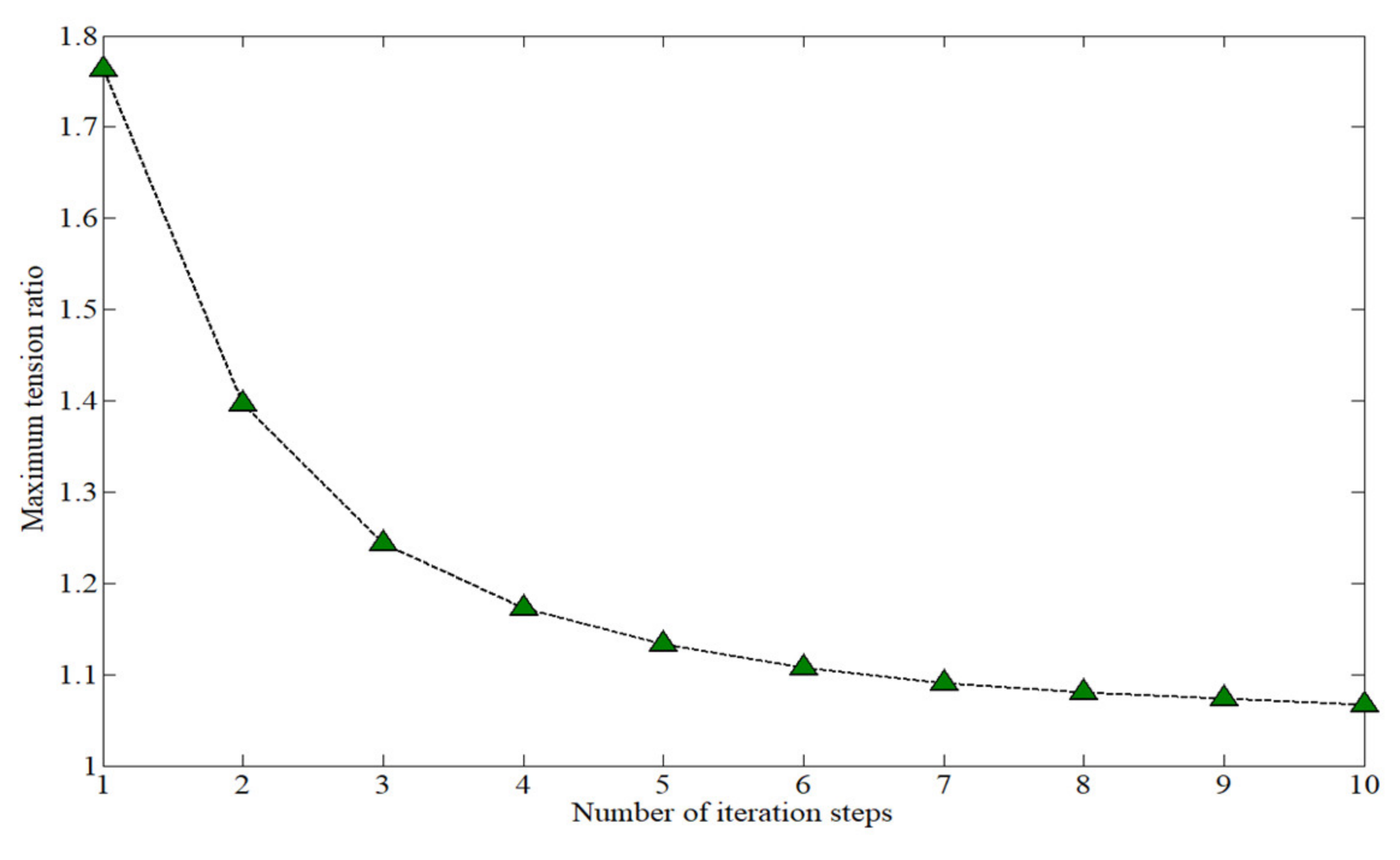
2.1. The Principle of Iterative FDM

The force density method, originally proposed by Linkwitz and Schek, is one of the most widely used methods for the form-finding analysis of mesh reflectors. This is because it is effective and easily implemented. For a three-dimensional tensegrity structure with N elements, the number of free coordinates is denoted as n f and the number of fixed coordinates as n g . The topology of tensegrity structures can be expressed by the connectivity matrix C N × n f + n g . The values of the elements in connectivity matrix C are shown in function (1). If member k connects nodes i and j ( i < j ) , then the connectivity matrix C, the i th column, and the j th column in the k row are 1   and 1 , respectively.
C k , p = 1                                             f o r   p = i . 1                                     f o r   p = j . 0                                         o t h e r w i s e .
The connectivity matrix C can be divided into two parts C f   C g , where C f N × n f is only related to free coordinates, and C g N × n g is only related to fixed coordinates.
If the free coordinate vector is denoted as [ x f   y f   z f ], and the fixed coordinate vector as [ x g   y g   z g ], then the linear equilibrium equations based on force density can be expressed as function (2),
C f T Q C f x f + C f T Q C g x g = P x C f T Q C f y f + C f T Q C g y g = P y C f T Q C f z f + C f T Q C g z g = P z
where Q is a diagonal matrix of force density coefficients,
Q = d i a g q .
The force density coefficient q i is the ratio of cable tension T i to cable length l i , that is,
q i = T i l i
For tensegrity structures only subjected to pretension, there is no external force. Therefore, the free coordinate can be expressed as
x f = C f T Q C f 1 C f T Q C g x g y f = C f T Q C f 1 C f T Q C g y g z f = C f T Q C f 1 C f T Q C g z g
The force density coefficient of each cable segment is assumed constant in the classical FDM, and the tension of cable segments can be noted as
T i = q i l i
Here, l i represents the new length of the i th segment, which can be solved by the interconnecting points’ spatial coordinates. When the length of the cable segment changes, the tension of the cable segment also changes, so the classical FDM results in uneven tension of the cable segment. To achieve a uniform mesh tension distribution, Morterolle [27] proposed an iterative FDM, the main idea of which is to update the force density coefficients and adjust the tension at each iteration step so that the tension of each cable segment in the final form-finding result is equal to the uniform tension T d . Then, at each iteration step, the force density coefficient after the i th cable segment is updated and can be expressed as follows, where p represents the current iteration step.
q i p + 1 = q i p T d T i p

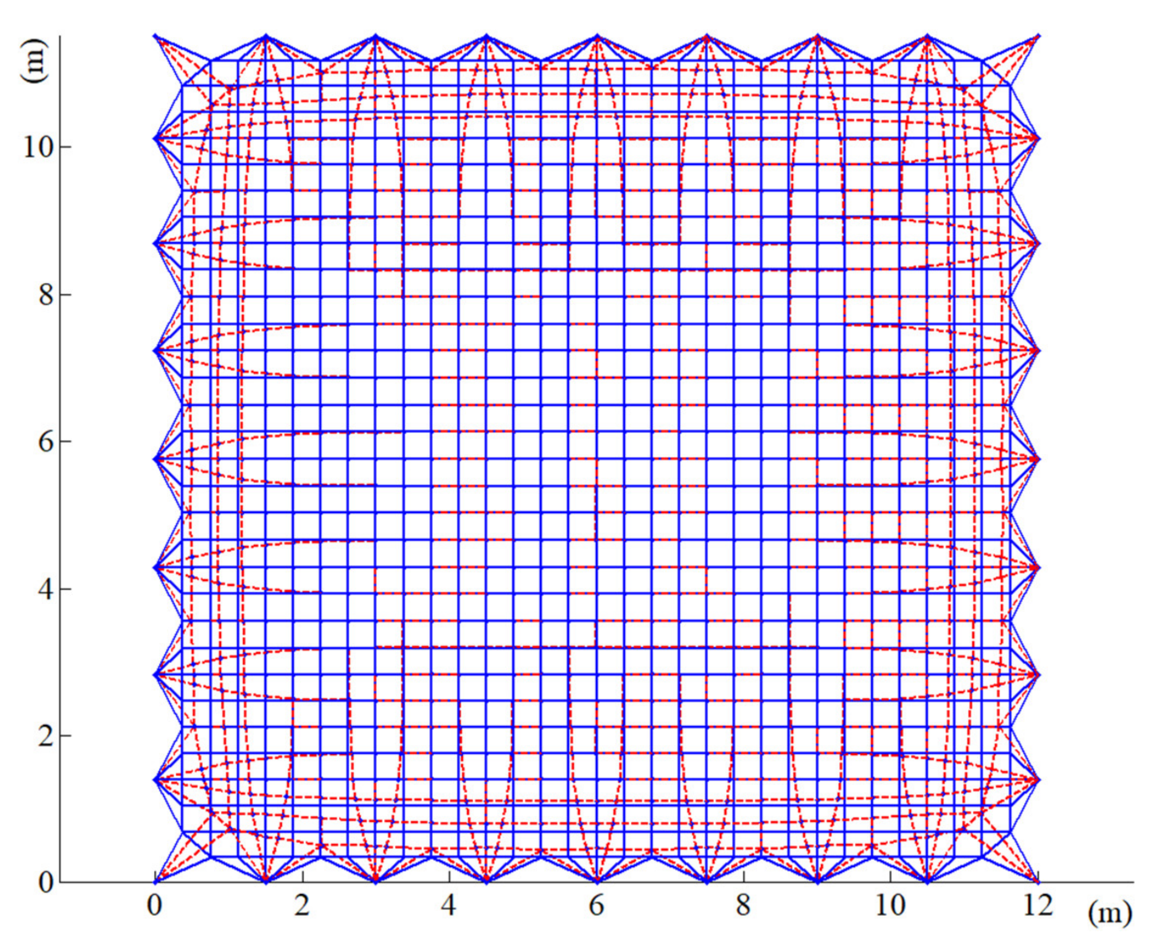
2.2. Form-Finding Analysis of a Mesh Reflector Based on Iterative FDM

The deployable parabolic cylinder antenna shown in Figure 1 consists of the large deployable structure and the mesh reflector, the effective reflection area of the given parabolic cylindrical antenna is 12 m × 10 m, and the overall mass is 200 kg, which is spliced by multiple modules and mainly used in the exploration of earth resources. The original iterative FDM introduced in Section 2.1 was used for the form-finding analysis of the mesh reflector. Under 10   N cable pretension, the result of the form-finding analysis is shown in Figure 2. The resulting mesh configurations are depicted with red dotted lines whereas the blue lines represent the initial configuration. As can be seen from the figure, the positions of the cables’ interconnecting points at the boundary change greatly, even though the positions of the internal cable interconnecting points change slightly. In summary, the cables’ configuration at the boundary will seriously affect antenna performance.
Figure 3 shows the maximum tension ratio of the cable in the iteration steps, with the ratio approaching 1. That is, the cable tension is uniform on the mesh reflector of the antenna. However, the precision of the antenna mesh reflector was seriously affected by the iterative FDM, and therefore, precision was not expected during the form-finding process.

2.3. Hybrid Iteration Force Density Method (HIFDM)

In order to ensure the precision of the antenna mesh reflection and make the tension of the inner cable uniform, a hybrid iterative method of force density coefficient was proposed. First, a new iteration format with the length as a variable was constructed for the boundary cables, Equation (8):
q i p + 1 = q i p L i p L o
where L i p is the length of the boundary i th cable segment in the p -th iteration, and L o was the theoretical length of the corresponding cable. It can be seen that the length of the boundary cable will trend to the original theoretical length with the increased number of iterations. It is worth noting that the iterative form has potential shape-preserving effects for irregular tensegrity structures.
Figure 4 shows the configuration of an antenna mesh reflector. The black line represents the boundary segment and the iterative form of the force density coefficient of Equation (8) is adopted in the iterative process. The inner cables are represented by dark cyan lines and the iterative format of the original force density coefficient, Equation (7), is adopted in the iterative process. The blue points represent the fixed-point positions. Considering that the net precision of the internal cables affected the pointing accuracy of the antenna mesh reflector, it can be used as the convergence index of the algorithm. The internal point configuration error is
δ n i = x n i x n i 2 + y n i y n i 2 + z n i z n i 2
Taking the theoretical configuration as the reference, the root mean square (RMS) of the antenna mesh reflector is
ψ = i = 1 N δ n i 2 N
Here, x n i , y n i , z n i represents the theoretical position coordinates of interconnecting points. The position coordinates after form-finding were marked x n i , y n i , z n i , and N is the total number of internal coordinates.
The result of form-finding by the HIFDM is shown in Figure 5.
According to the results shown in Figure 5, the form-finding process based on the HIFDM has a potential shape-preserving effect between the boundary cables and the inner cables. In addition, the position of the interconnecting points of the cables does not change from before to after the form-finding. The internal cable segment tension is shown in Figure 6. According to the figure, the value of the internal cable tension is very close to 10 N, so the internal cable tension is uniform. Figure 7 shows the tension value of the boundary cable segments. The HIFDM ensures the position of the interconnecting points of the boundary cable, and the maximum tension ratio is 4.8445.
Figure 8 and Figure 9 show the maximum tension ratio of the internal cables and the precision of the mesh reflector with the number of iterations, respectively. The maximum tension ratio is 1.0011 and the RMS is 6.6   mm .

3. Optimization Analysis of Antenna Reflector Accuracy Based on GA

3.1. Optimization Target

The uneven length of the boundary cable segments and different tension directions can have a great influence on mesh reflector precision. To further improve the accuracy of the antenna reflector, this section will further optimize the boundary cable segment tensions.
Compared with traditional optimization algorithms, genetic algorithms (GAs) are effective at searching for improvements. Additionally, GAs are not limited by search space and the optimization process does not involve specific parameter relationships between variables and objective functions [28,29,30]. Therefore, GAs have the potential to optimally solve the problem of many boundary cables and uneven cable tension. The RMS of a mesh reflector can be used as an optimization criterion to measure the rationality of the distribution of cable tension. Optimization of the boundary tension of a cable segment aims to reduce the RMS of the antenna reflector. Thus, the objective function is
min ψ T m 1 , T m 1 , , T m n
Here, T m i is the pretension at the cable segment i , and the number of boundary cable segments is n . All cable segments should be in the tensioned state in the optimization process; that is, the constraint condition of optimization is
T m i > 0
The optimization process is as follows:
  • First, the pretension of the boundary segment obtained according to the HIFDM in Section 2 was used as the initial distribution strategy. Δ T m i ,   Δ T m i is the floating range allowed by the pretension. The N pretension allocation schemes, T m i j | i = 1 ~ n , j = 1 ~ N , were randomly generated to form the initial population. The adjusted pretension of the boundary segment was obtained according to Equation (13), and r a n d i is the uniformly random number from 1 to 1 .
    T m i = T m i + r a n d i Δ T m i r a n d i 1 , 1    
  • T m i j is introduced into the form-finding model of the HIFDM and the RMS of the antenna mesh reflector was obtained. The process was repeated until the RMS values of all initial populations ψ j | j = 1 ~ N were obtained.
  • The fitness function value was calculated according to ψ j | j = 1 ~ N . Then, the roulette model was used to screen the individuals based on the fitness function value and a population composed of relatively superior individuals was obtained.
  • A cross mutation operation was carried out on the screened population and the optimal individual was retained according to certain probabilities to form the next-generation population.
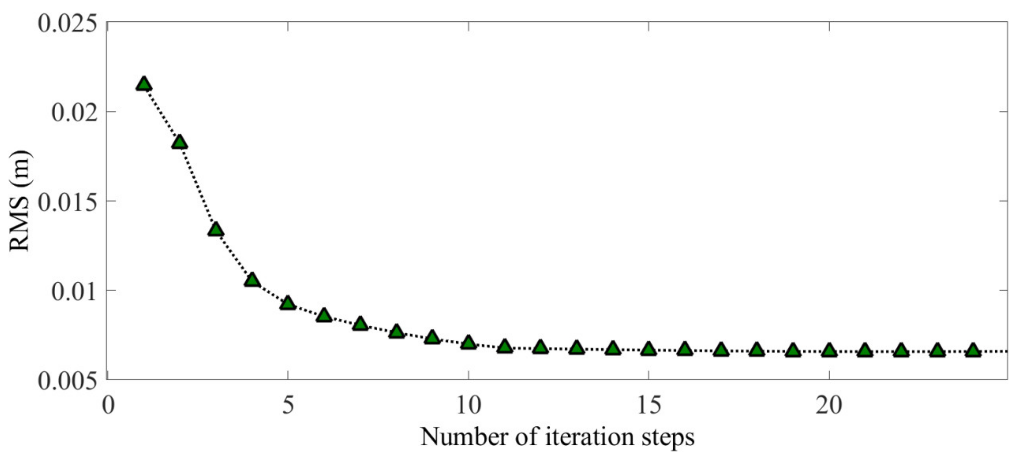
  • Steps (2) through (4) were repeated until the RMS difference value between any two generations later was less than the given precision t o l (in this paper t o l = 0.001   mm ); that is, the population convergence and the optimal pretension distribution scheme were obtained.

3.2. Optimization Results Analysis

This study adopted an adaptive GA proposed by Lin. The population size was set to 50 and the genetic algebra to 400. Based on the above optimization steps, the final form-finding result is shown in Figure 10. The RMS of the internal mesh reflector decreased from 6.6 mm to 4.3 mm with the accuracy improved by 34.8%. Figure 11 shows the RMS difference value between the two generations of the population, indicating the population convergence starting from generation 282 and the optimal solution.
Figure 12 shows the optimized form-finding configuration of the mesh reflector. The interconnecting points of the cables are very close to the theoretical position. It can be seen from the internal tension of the cable segments shown in Figure 13, as compared with the previous optimization, that the internal cable segment tension was more concentrated around 10 N and the maximum tension ratio was 1.001. Figure 14 shows the tension value of the boundary cable segments. The maximum tension ratio compared with that before the optimization was increased to 5.608. The maximum change of the boundary cable tension value from the original scheme was around 1 N, which indicates that the precision of the mesh reflector was sensitive to the distribution of tension of the boundary cables. However, a reasonable strategy for the boundary cable tension will help to improve the shape accuracy of the antenna mesh reflector.

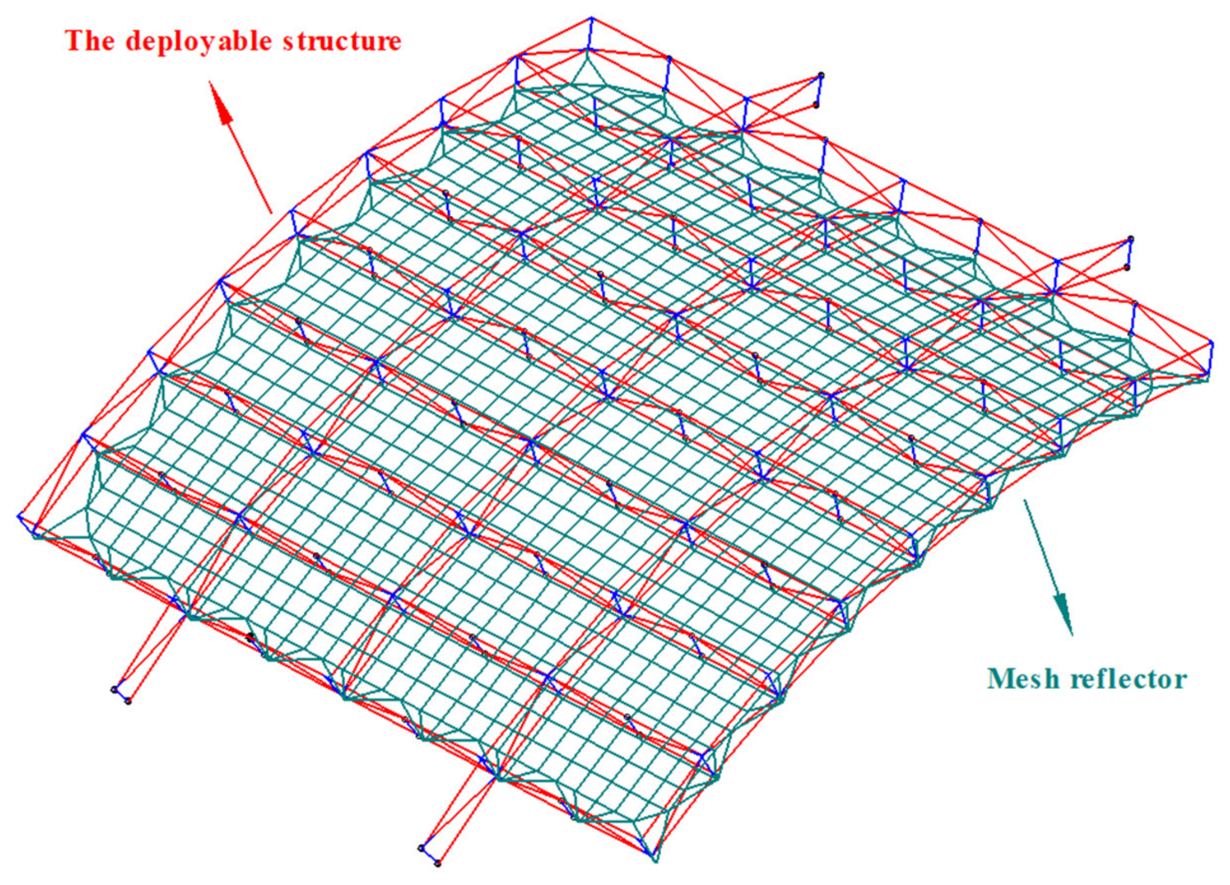
4. Form-Finding Analysis of an Antenna Reflector with the Deformation of a Deployable Structure

Due to the large size of its deployable structure, the antenna has low stiffness. Deformation occurs under the action of pretension of the cables so that the position of connecting points between cables and the deployable structure changes. This will lead to the cable segment pretension obtained in Section 3, and even cause the pretension failure of the antenna mesh reflector. Therefore, it is necessary to design the pretension of the antenna mesh reflector such that the elastic deformation of the deployable structure is considered for practical engineering applications.

4.1. Static Model of the Deployable Structure Based on the FEM

The deployable structure is shown in Figure 15. Three different kinds of sub-elements, the basic unit on the directrix (BUD), the MBUG (main basic unit on the generatrix (MBUG), and the assistant basic unit on the generatrix (ABUG) make up the basic sub-ring.
Three-dimensional beam elements were used to discretize the deployable structure in this study. According to the finite element theory, the mechanical model of the three-dimensional beam element was expressed by Equation (14), which indicates the relationship between node load and node displacement. The specific derivation process can be referred to in the literature [31].
K e δ e s e = 0
s e is node load, δ e is node displacement, and K e is the element stiffness matrix. They are all defined in local coordinates. Through the rotation matrix of pose R e , they can be transformed into a global coordinate system.
First, the stiffness matrix of the element was represented by K i e m n . Here, subscript i and superscript m , n are beam element numbers and node numbers at both ends, respectively. Then, through the corresponding beam element cosine matrix R i e , the stiffness matrix in the global coordinate system K ¯ i m n was obtained. Next, K ¯ i m n was promoted K i , so that the dimension of K i was consistent with the total stiffness matrix. Finally, the total stiffness matrix was obtained by adding up the stiffness of all elements.
Figure 16 shows how to derive the total stiffness matrix K so the static model of the deployable structure can be expressed as Equation (15):
Q = K Δ
{∆} represents the node deformation under the node load { Q }.
Figure 16. Set of total stiffness matrices.
Aerospace 09 00239 g016

4.2. Iterative Strategy for Form-Finding of an Antenna Mesh Reflector

Based on the static model and Equation (15), this section proposes an antenna mesh reflector form-finding strategy that considers the elastic deformation of the deployable structure. Due to elastic deformation caused by cable tension, the fixed points (connecting points between the cable and the deployable structure) position will change. Thus, the length of cable segments will change again after form-finding. This means that the cable tension applied to a deployable structure is not the same as that before calculation, so it is necessary to determine the location of the fixed points after elastic deformation of the deployable structure by iterative strategy.
First, the design parameters and physical parameters of the deployable parabolic cylinder antenna were given, and the FEM model of the deployable structure was given based on the construction process introduced in Section 4.1. Then, the configuration of the mesh reflector of the antenna was given and the topology connectivity matrix C was obtained. According to the given initial pretension of the cable segment and the initial position of interconnecting free points x i   y i   z i , we calculated the initial length of the cable segment l i to obtain the initial force density coefficient q i of each cable segment. Then, based on the HIFDM proposed in this paper, the force density coefficient when the RMS of the inner mesh reflector converges was obtained (convergence indicator t o l = 0.001   mm ) and the tension of each cable segment after form-finding could be solved. Finally, we extracted the tension vector F n of connecting points between the cable and deployable structure, which we introduced into the FEM model to calculate the elastic deformation Δ r n . The updated point positions were substituted into the HIFDM to obtain the new tension vector F n + 1 and the elastic deformation Δ r n + 1 was calculated once more. The error of two elastic deformities of the deployable structure were compared; that is, the change of the cable segment tension connected with fixed points after elastic deformation of the deployable structure was considered, and, according to the convergence index (convergence indicator tof = 1 mm), whether to proceed to the next iteration was determined.
The form-finding analysis of the antenna reflector process was shown in Figure 17:

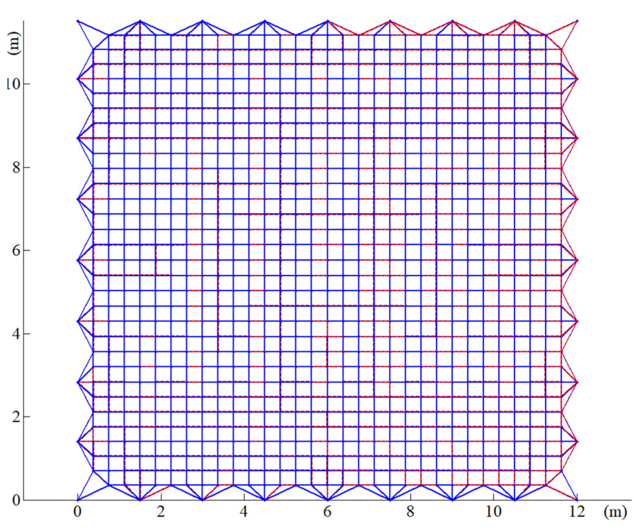
4.3. Form-Finding Results Analysis

Figure 18 shows the form-finding configuration of the mesh reflector, which considered the elastic deformation of the deployable structure.
The red dotted line represents the configuration after form-finding and the blue line represents the initial configuration. It can be seen from the figure that due to the elastic deformation of the deployable structure, the position of the boundary cable and the connection point of the deployable structure changed (such as the position of the point shown in the scaled view). It can be concluded from the final conclusion of this paper, the precision of the antenna mesh reflector was 8.38   mm , which means that the elastic deformation of the deployable structure affected the shape precision of the mesh reflector. To improve the precision of the antenna mesh reflector, the tension of the boundary cable segment was optimized according to the optimization method in Section 3.
Figure 19 and Figure 20 show the tension of the inner cable segments and the boundary cable segments, respectively, while the maximum tension ratios were 1.0372 and 5.5898. Figure 21 shows that after four iterations, the error of elastic deformation of the deployable structure was less than 1 mm, and the algorithm converged. The results show that the elastic deformation of the deployable structure affected the uniformity of the cable tension of the mesh reflector.
Figure 22 shows the variation trend of the mesh reflector accuracy of the antenna under different pretension after considering elastic deformation of the deployable structure. It can be seen from the figure that with the increase of pretension, the elastic deformation of the deployable structure had an increasing influence on the precision of the mesh reflector. Therefore, the reasonable design of pretension has far-reaching consequences for the precision of the antenna mesh reflector.

5. Conclusions

Based on the traditional iterative FDM and with the length of the cable segment as an iterative variable, an iterative scheme of force density coefficient was proposed to ensure the shape precision of an antenna mesh reflector. On the one hand, the iterative method of the force density coefficient based on length can adapt to the boundary cable segment with uneven loading, different length, and irregular arrangement. On the other hand, the application of the traditional iterative force density method ensures the tension uniformity of the inner cable of the antenna reflector. Thus, the HIFDM has the potential for the pretension design of antenna mesh reflectors. To further improve the precision of the mesh reflector, GAs were used to optimize the tension of the boundary cable segments. The optimization results showed that the internal tension tends to be 10 N and the tension fluctuation of the boundary cable segment is relatively small. This means that any slight change of tension will lead to a large fluctuation in the shape precision.
To investigate the coupling problem between the elastic deformation of a deployable structure and the tension of cable segments, a static model of the deployable structure was established based on FEM with an iterative strategy for form-finding of an antenna mesh reflector. It was found that the elastic deformation of the deployable structure will reduce the uniformity of cable tension and affect the precision of the antenna reflector. When the pretension increases, the form-finding result of the cable net will worsen. This is because the deployable structure has a large size and is prone to deformation under the influence of the cable segment pretension. Therefore, the selection of mesh reflector pretension is critical to ensure the accuracy of the antenna’s in-orbit shape surface.
Due to the complex environmental conditions in space, the accuracy of the antenna reflector will inevitably decrease, which affects the accurate transmission of antenna signals. Additionally, the deformation caused by stress release, fatigue damage, and other factors will affect the accuracy of the antenna during continuous in-orbit operation. Therefore, the in-orbit self-adjustment of the antenna reflector precision is a prime objective of future research.

Author Contributions

Conceptualization, J.D., J.C. and Z.S.; methodology, J.D., Z.S. and C.C.; software, J.D., Z.S. and J.L.; validation, J.D., Z.S. and J.L.; formal analysis, J.D., Z.S. and J.C.; investigation, J.D., C.C. and J.L.; resources, Z.S. and J.C.; data curation, J.D., Z.S. and J.L.; writing—original draft preparation, J.D. and Z.S.; writing—review and editing, J.D. and Z.S.; visualization, J.D., Z.S. and C.C.; supervision, J.D., Z.S. and J.C.; project administration, J.C., C.C. and J.L.; funding acquisition, J.C., C.C. and J.L. All authors have read and agreed to the published version of the manuscript.

Funding

The work was supported by the National Natural Science Foundation of China (Grant number 52075242).

Institutional Review Board Statement

Not applicable.

Informed Consent Statement

Not applicable.

Data Availability Statement

Not applicable.

Conflicts of Interest

The authors declare no conflict of interest.

References

  1. Liu, R.; Shi, C.; Guo, H.; Li, B.; Tian, D.; Deng, Z. Review of Space Deployable Antenna Mechanisms. J. Mech. Eng. 2020, 56, 1. [Google Scholar]
  2. Guo, J.; Zhao, Y.; Xu, Y.; Li, Y.; Yao, J. Design and analysis of truss deployable antenna mechanism based on a novel symmetric hexagonal profile division method. Chin. J. Aeronaut. 2020, 34, 87–100. [Google Scholar] [CrossRef]
  3. Duan, B. The State-of-the-art and Development Trend of Large Space-borne Deployable Antenna. Electro-Mech. Eng. 2017, 33, 1–14. [Google Scholar]
  4. Lin, F.; Chen, C.; Chen, J.; Chen, M. Modelling and analysis for a cylindrical net-shell deployable mechanism. Adv. Struct. Eng. 2019, 22, 3149–3160. [Google Scholar] [CrossRef]
  5. Fan, Y.; Li, T.; Ma, X.; Li, Z. Form-finding method of equal tension cable networks for space mesh antennas. J. Xi’an Dianzi Keji Daxue Xuebao/J. Xidian Univ. 2015, 42, 49–55. [Google Scholar]
  6. Maddio, P.D.; Meschini, A.; Sinatra, R.; Cammarata, A. An optimized form-finding method of an asymmetric large deployable reflector. Eng. Struct. 2019, 181, 27–34. [Google Scholar] [CrossRef]
  7. Yuan, P.; He, B.; Zhang, L.; Yuan, Z.; Ma, X. Pretension design of cable-network antennas considering the deformation of the supporting truss: A double-loop iterative approach. Eng. Struct. 2019, 186, 399–409. [Google Scholar] [CrossRef]
  8. Khatibinia, M.; Hosseinaei, S.; Sarafrazi, S.R. Efficiency of dynamic relaxation methods in form-finding of tensile membrane structures. SN Appl. Sci. 2019, 1, 1–13. [Google Scholar] [CrossRef] [Green Version]
  9. You, G. A Structural Analysis Method for Cable-Beam Composite Structure. Math. Probl. Eng. 2020, 4, 1–13. [Google Scholar] [CrossRef]
  10. Li, H.; Yang, J. Application of nonlinear finite element method in the form-finding of lattice shells. Spat. Struct. 2016, 4, 12–16. [Google Scholar]
  11. Xu, X.; Wang, Y.; Luo, Y. Finding member connectivities and nodal positions of tensegrity structures based on force density method and mixed integer nonlinear programming. Eng. Struct. 2018, 166, 240–250. [Google Scholar] [CrossRef]
  12. Xu, R.; Li, D.X.; Liu, W.; Jiang, J.; Liao, Y.; Wang, J. Modified nonlinear force density method for form-finding of membrane SAR antenna. Struct. Eng. Mech. 2015, 54, 1045–1059. [Google Scholar] [CrossRef]
  13. Aboul-Nasr, G.; Mourad, S.A. An extended force density method for form finding of constrained cable nets. Case Stud. Struct. Eng. 2015, 3, 19–32. [Google Scholar] [CrossRef] [Green Version]
  14. Moskaleva, A.; Ruiz, M.A.F.; Martín, L.M.G.; Frolovskaia, A.; Gerashchenko, S.; Hernandez-Montes, E. Form-finding of Bionic Structures Using the Force Density Method and Topological Mapping. Civ. Eng. Arch. 2019, 7, 65–74. [Google Scholar] [CrossRef]
  15. Cai, J.; Wang, X.; Deng, X.; Feng, J. Form-finding method for multi-mode tensegrity structures using extended force density method by grouping elements. Compos. Struct. 2018, 187, 1–9. [Google Scholar] [CrossRef]
  16. Pauletti, R.M.O.; Fernandes, F.L. An outline of the Natural Force Density Method and its extension to quadrilateral elements. Int. J. Solids Struct. 2019, 9, 423–438. [Google Scholar] [CrossRef]
  17. Wei, S.; Ohsaki, M. Geometry and topology optimization of plane frames for compliance minimization using force density method for geometry model. Eng. Comput. 2020, 37, 1–18. [Google Scholar]
  18. Liu, M.; Cao, D.; Li, J.; Zhang, X.; Wei, J. Dynamic modeling and vibration control of a large flexible space truss. Meccanica 2022, 57, 1017–1033. [Google Scholar] [CrossRef]
  19. Zhang, S.; Zhang, S.; Zhang, Y.; Ye, J. Force density sensitivity form-finding design method for cable-mesh reflector antennas considering interactive effects between cable network and supporting truss. J. Eng. Struct. 2021, 244, 112722. [Google Scholar] [CrossRef]
  20. Yang, G.; Duan, B.; Du, J.; Zhang, Y. Shape pre-adjustment of deployable mesh antennas considering space thermal loads. Proc. Inst. Mech. Eng. Part G. J. Aerosp. Eng. 2018, 232, 143–155. [Google Scholar] [CrossRef]
  21. Wang, Y.; Xu, X.; Luo, Y. Form-finding of tensegrity structures via rank minimization of force density matrix. Eng. Struct. 2021, 227, 111419. [Google Scholar] [CrossRef]
  22. Dai, L.; Xiao, R. Optimal design and analysis of deployable antenna truss structure based on dynamic characteristics restraints. Aerosp. Sci. Technol. 2020, 106, 106086. [Google Scholar] [CrossRef]
  23. Li, P.; Liu, C.; Tian, Q.; Hu, H.; Song, Y. Dynamics of a Deployable Mesh Reflector of Satellite Antenna: Form-Finding and Modal Analysis. J. Comput. Nonlinear Dyn. 2016, 11, 041017. [Google Scholar] [CrossRef]
  24. Li, P.; Liu, C.; Tian, Q.; Hu, H.; Song, Y. Dynamics of a Deployable Mesh Reflector of Satellite Antenna: Parallel Computation and Deployment Simulation. J. Comput. Nonlinear Dyn. 2016, 11, 061005. [Google Scholar] [CrossRef]
  25. Liu, R.; Guo, H.; Liu, R.; Tangb, D.; Wangb, H.; Denga, Z. Design and form finding of cable net for a large cable-rib tension antenna with flexible deployable structures. Eng. Struct. 2019, 199, 109662. [Google Scholar] [CrossRef]
  26. Niu, S.; Li, K.; Liu, J.; Bao, H. A Refined Shape Sensing Method for Skin Antenna Structure Based on Inverse Finite Element Method. Appl. Sci. 2020, 10, 7620. [Google Scholar] [CrossRef]
  27. Morterolle, S.; Maurin, B.; Quirant, J.; Dupuy, C. Numerical form-finding of geotensoid tension truss for mesh reflector. Acta Astronaut. 2012, 76, 154–163. [Google Scholar] [CrossRef] [Green Version]
  28. Han, X.K.; Zhang, Z. Topological Optimization of Phononic Crystal Thin Plate by a Genetic Algorithm. Sci. Rep. 2019, 9, 8331. [Google Scholar] [CrossRef] [Green Version]
  29. Luo, X.-Q. Comparision between Readitional Optimized Algorithm and Heredity Algorithm. J. Hubei Univ. Technol. 2007, 3, 32–34. [Google Scholar]
  30. Marrouchi, S.; Hessine, M.B.; Chebbi, S. New Strategy Based on Combined Use of Genetic Algorithm and Gradient to Solve the UC Problem: Theoretical Investigation and Comparative Study. Int. J. Eng. Technol. 2018, 7, 44–50. [Google Scholar] [CrossRef] [Green Version]
  31. Song, Z.; Chen, C.; Jiang, S.; Chen, J.; Liu, T.; Deng, W.; Lin, F. Optimization Analysis of Microgravity Experimental Facility for the Deployable Structures Based on Force Balance Method. Microgravity Sci. Technol. 2020, 32, 773–785. [Google Scholar] [CrossRef]
Figure 1. The deployable parabolic cylinder antenna.
Aerospace 09 00239 g001
Figure 2. The result of form-finding analysis of mesh reflectors.
Aerospace 09 00239 g002
Figure 3. Maximum tension ratio.
Aerospace 09 00239 g003
Figure 4. The configuration of an antenna mesh reflector.
Aerospace 09 00239 g004
Figure 5. The result of form-finding analysis of a mesh reflector by the HIFDM.
Aerospace 09 00239 g005
Figure 6. The internal cable segment tension.
Aerospace 09 00239 g006
Figure 7. The boundary cable segment tension.
Aerospace 09 00239 g007
Figure 8. Maximum tension ratio.
Aerospace 09 00239 g008
Figure 9. The precision of the mesh reflector.
Aerospace 09 00239 g009
Figure 10. Convergence process of GA.
Aerospace 09 00239 g010
Figure 11. Difference value of the RMS between adjacent algebras.
Aerospace 09 00239 g011
Figure 12. The optimized form-finding configuration of the mesh reflector.
Aerospace 09 00239 g012
Figure 13. The internal cable segment tension.
Aerospace 09 00239 g013
Figure 14. The boundary cable segment tension.
Aerospace 09 00239 g014
Figure 15. The deployable structure.
Aerospace 09 00239 g015
Figure 17. The form-finding analysis of the antenna reflector process.
Aerospace 09 00239 g017
Figure 18. The form-finding configuration of the mesh reflector.
Aerospace 09 00239 g018
Figure 19. The internal cable segment tension.
Aerospace 09 00239 g019
Figure 20. The boundary cable segment tension.
Aerospace 09 00239 g020
Figure 21. Elastic deformation error.
Aerospace 09 00239 g021
Figure 22. The variation trend of the accuracy of the antenna reflector under different pretension.
Aerospace 09 00239 g022
Publisher’s Note: MDPI stays neutral with regard to jurisdictional claims in published maps and institutional affiliations.

