Article

An Efficient Blade Design Method of a Ducted Fan Coupled with the CFD Modification

School of Aeronautics, Northwestern Polytechnical University, Xi’an 710072, China
*
Author to whom correspondence should be addressed.
Aerospace 2022, 9(5), 241; https://doi.org/10.3390/aerospace9050241
Submission received: 28 February 2022 / Revised: 5 April 2022 / Accepted: 25 April 2022 / Published: 26 April 2022
(This article belongs to the Section Aeronautics)

Abstract

:
In order to improve the design accuracy of the blade design method of a ducted fan based on the blade element momentum theory, the design was modified by the CFD calculation with higher accuracy to propose an integrated and efficient design method for the rotor and stator. Firstly, a fast blade design method for the ducted fan was established based on the blade element momentum theory, and the initial design of the rotor and stator was carried out. Then, the performance of the designed ducted fan was calculated by the CFD method, and the rotor and stator were modified and redesigned according to the CFD results. Such continuous iterations finally made the design results basically consistent with the CFD results so as to improve the design accuracy. The blade design of different ducted fans shows that the unsteady CFD method based on the sliding mesh has higher accuracy and applicability than the MRF method, and the efficient blade design method established in this paper can meet the thrust demand with a small amount of the CFD modification. The thrust design accuracy of the ducted fan was increased by 11.362%, and the torque design accuracy was increased by 8.141%.

1. Introduction

In 2013, the USA department of Defense Advanced Research Projects Agency launched the project for the vertical take-off and landing experimental plane (VTOL X-Plane). Aurora’s “Lightning Strike” UAV with a tilting electric ducted fan won the bid. In 2017, the prototype of the all-electric vertical take-off and landing aircraft named “Lilium Jet” completed its first flight, which also used the electric ducted fan. The U.S. Air Force also launched the “Agility Prime” electric vertical take-off and landing vehicle demonstration and verification project in February 2020. The VTOL aircraft with the electric ducted fan as the main power has become one of the important development directions in future aviation.
The ducted fan with the same disk load has higher aerodynamic efficiency and safety than the isolated propeller at low speed [1,2]. The blade design of the ducted fan is generally based on fast methods, such as the blade element momentum theory, lift line model, and panel method. Liu derived the blade element momentum theory of the ducted fan [3]. Coney used the annular vortex model and symmetrical vortex model to simulate the duct and established the blade design method of the ducted fan based on the lift line model [4]. Stubblefield adopted the optimal circulation design method [5] to design the blade of the ducted fan based on the lift line model [6]. In addition, Yang optimized the torsion angle of the blade of the ducted fan based on the panel method [7], Yu used the panel method to optimize the blade of the ducted fan [8], and Wang optimized the inlet of distributed ducted fan system based on the panel method [9]. It can be seen that the design and optimization of the blade of the ducted fan are basically based on the fast method, so the accuracy of the fast method determines the accuracy of the design. However, due to the simplification of these fast methods, there is inevitably a certain deviation between the design result and the actual performance of the ducted fan.
With the continuous development of computational fluid dynamics (CFD), the high-precision CFD method based on Navier–Stokes (N–S) equations has been widely used to obtain the performance and flow field of the ducted fan, such as the multiple reference frame (MRF) method and unsteady CFD method based on the sliding mesh or overset mesh. Xu numerically simulated the unsteady flow field of the ducted fan by solving the compressible Euler equations based on the overset mesh [10]. Echavarria used the unsteady CFD method based on the overset mesh to study the blade number effect on the performance of the ducted fan and carried out the sensitivity analysis of the grid and time step [11]. Wang verified the feasibility of the MRF method to obtain the performance of the ducted fan [12]. In order to improve the computational efficiency of the CFD method, the complex blade structure was replaced by a disk in the CFD calculation to develop the actuator disk method [13,14] and momentum source method [15,16,17], and different scholars carried out the optimization design of the duct based on the momentum source method [18,19]. At present, the high-precision CFD method is basically used in the flow field simulation, performance analysis, and optimization design of the duct but is rarely used in the optimization design of the blade. This is because the CFD calculation of the ducted fan with complex blade structures takes a long time, especially for an unsteady CFD calculation, and the optimization design requires a lot of calculations. Even if the surrogate-based optimization [20] is used, the efficiency of the optimization design of the blade based on the CFD method is still low.
Therefore, in order to make up for the lack of accuracy of the design method based on the blade element momentum theory and keep the design method fast, this paper combined the blade element momentum theory with the CFD method, modified the design by the CFD results, and put forward an integrated and efficient design method of the rotor and stator, which could quickly design the blade of the ducted fan according to the thrust demand. The feasibility of the design method was verified.

2. Numerical Simulation Methods

The performance of the 150 ducted fan including the rotor and stator shown in Figure 1 was tested first to verify the numerical simulation method. The 150 ducted fan is named by the inner diameter of the duct. The ducted fan has a length of L = 255   mm , an inlet length of L in = 40   mm , an outlet length of L out = 100   mm , a hub radius of R h = 30   mm , an inner radius of R = 75   mm , a maximum radius of R max = 96   mm , and an outlet diffusion angle of α e = 3 ° shown in Figure 2. The rotor has a blade number of N r = 10 and a blade tip clearance of 0.5 mm, and the stator has a blade number of N s = 6 .
The experimental site of the ducted fan and connection mode of various instruments are shown in Figure 3. The ATI delta force/torque sensor was used to measure the aerodynamic force. The “Eagle tree system” was used to measure the rotating speed. The Faith DC power supply and “Hobbywing X-Rotor Pro HV 80A” were used to power the motor. The experiment was in no incoming flow state. In this state, the “HD_wall” shown in Figure 2 basically does not generate the aerodynamic force, so it was omitted for the convenience of installation.
The performance of the 150 ducted fan was calculated by the MRF method and unsteady CFD method based on the sliding mesh by solving Reynolds-averaged N-S equations and adopting the k-ω SST turbulence model. The grid independence of the blade grid and background grid was verified respectively in the MRF method. The Y+ value was always around 1 when different meshes were generated. The results are shown in Figure 4 and Figure 5 and Table 1 and Table 2 below. The results show that the calculation results of different grids have little difference, so 1.04 million background grid and 1.92 million blade grid were used in the numerical simulation. The comparison between the test results and the calculation results is shown in Figure 6. The total thrust and total torque obtained by the two numerical simulation methods are in good agreement with the test results.

3. Fast Blade Design Method of the Ducted Fan

3.1. Blade Element Momentum Theory

The total thrust of the ducted fan comes from the rotor, stator, and duct. The ratio of the total blade thrust T p in the total thrust T is a 1 , and the ratio of the rotor thrust T r in the total blade thrust T p is a 2 .
T p = T r + T s
a 1 = T p T
a 2 = T r T p
The rotor element analysis is shown in Figure 7, where V 0 is the free stream velocity, Ω is the rotating speed of the rotor, α r is the angle of attack of the rotor element, β is the interference angle, γ is the angle between rotor element lift d L and the resultant of d L and rotor element drag d D , φ r is the inflow angle of the rotor element, φ 0 is the geometric inflow angle, W r is the total velocity of the rotor element, V a 1 is the axial induced velocity at the rotor, V t 1 is the tangential induced velocity at the rotor, and V is the geometric induced velocity of the rotor.
The forces of the rotor element are as Equations (4) and (5) according to the momentum theory, where V aw is the axial induced velocity at the wake.
d T r = 2 a 1 a 2 π r ρ ( V 0 + V a 1 ) V aw d r
d F r = 4 π r ρ ( V 0 + V a 1 ) V t 1 d r
The increase in the total pressure is related to the rotor. According to the pressure change, the thrust of the rotor element can be expressed as Equation (6).
d T r = 2 π r ρ ( V 0 + V aw / 2 ) V aw d r
According to Equations (4) and (6), the relationship between the axial induced velocities is obtained.
V aw = 2 ( a 1 a 2 1 ) V 0 + 2 a 1 a 2 V a 1
The following relationship can be from Figure 7.
tan ( φ r + γ ) = d F r d T r = 2 V t 1 a 1 a 2 V aw
So the relationship between the induced velocities at the rotor is as follows.
V t 1 = a 1 a 2 ( a 1 a 2 1 ) V 0 tan ( φ r + γ ) + a 1 2 a 2 2 V a 1 tan ( φ r + γ )
According to the relationship between the induced velocity and V shown in Equation (10), the relationship between V and the induced velocity can be established, as shown in Equation (11).
V t 1 = V V a 1 tan φ r
V a 1 = V + a 1 a 2 ( 1 a 1 a 2 ) V 0 tan ( φ r + γ ) tan φ r 1 + a 1 2 a 2 2 tan ( φ r + γ ) tan φ r
The inflow velocity of the stator is directly calculated by the velocity behind the rotor in the axial flow state so as to design the angle of attack of the stator element to offset the torque of the rotor. The stator converts the tangential velocity behind the rotor into an axial velocity, and the stator itself provides another part of the thrust.

3.2. Minimum Energy Loss

Assuming that the circulation of the rotor element produces a disturbance of Δ Γ r , which causes the rotor thrust and rotor torque to change Δ T r and Δ Q r , respectively. The ratio of the useful work done by the rotor to the absorbed energy is k , as shown in Equation (12).
k = V 0 Δ T r Ω Δ Q r
Without considering the drag effect, the changes of the rotor thrust and torque are as follows.
Δ T r = ρ Δ Γ r ( Ω r V t 1 ) d r
Δ Q r = ρ Δ Γ r ( V 0 + V a 1 ) r d r
Then Equation (15) can be obtained from Equations (12)–(14) and the geometric relationship shown in Figure 7.
k = V 0 Ω r ( Ω r V t 1 ) ( V 0 + V a 1 ) = V 0 V 0 + V
The minimum energy loss requires that the radial distribution of the k of the rotor is constant [3], so the radial distribution of the V of the rotor is also constant. Therefore, the state of each element of the blade can be obtained by solving the k that meets the thrust demand, and then the design of the rotor and stator can be carried out.

3.3. Fast Design Method of the Rotor and Stator

The fast design method of the rotor and stator of the ducted fan aims to design the blade of the ducted fan that meets the thrust demand. Before the design, the design state and the design thrust should be defined, and the initial a 1 and a 2 should be given according to the duct shape. By selecting an appropriate airfoil, the design angle of attack of the rotor element α r and the corresponding lift coefficient C l and drag coefficient C d should be given, and the aerodynamic curves C l ( α s ) and C d ( α s ) of the stator element should be given. The basic design steps of the fast design method of the rotor and stator of the ducted fan are as follows.
  • The rotor and stator are divided into N blade element sections, respectively;
  • Rotor design;
For the known V , the inflow angle of the rotor element is obtained by Equation (16).
φ r = arctan ( V 0 + V Ω r )
Then the corresponding induced velocity is obtained through Equations (10) and (11) so as to obtain the total velocity and circulation of the rotor element.
W r = ( Ω r V t 1 ) 2 + ( V 0 + V a 1 ) 2
Γ r = 4 π r N r V t 1
The chord length of the rotor element is obtained by Equation (19).
b r = 2 Γ r W r C l
The thrust and torque of the rotor element are as follows:
d T r = 1 2 ρ W r 2 b r ( C l cos φ r C d sin φ r ) d r
d Q r = 1 2 ρ W r 2 b r ( C l sin φ r + C d cos φ r ) r d r
Then the total thrust of the ducted fan is obtained by Equation (22).
T = R h R N r 2 a 1 a 2 ρ W r 2 b r ( C l cos φ r C d sin φ r ) d r
The Newton iteration method is used to solve the V meeting the design thrust to obtain the state of each rotor element. Then, the chord length of each rotor element is obtained from Equation (19), and the corresponding torsion angle is obtained by Equation (23).
θ r = φ r + α r
3.
Stator design.
After the rotor design, the inflow angle and total velocity of the stator element are determined by Equations (24) and (25), according to the induced velocity of the rotor.
tan φ s = V 0 + V a 1 V t 1
W s = V t 1 2 + ( V 0 + V a 1 ) 2
For the known torque of the rotor element d Q r , inflow angle of the stator element φ s and chord length of the stator b s , the appropriate angle of attack of the stator element α s is solved according to the aerodynamic curves C l ( α s ) and C d ( α s ) , so that the torque of the stator element d Q s is the same size and opposite direction as the d Q r at the corresponding position.
The thrust and torque of the stator element are as follows.
d T s = 1 2 ρ W s 2 b s ( C l cos φ s C d sin φ s ) d r
d Q s = 1 2 ρ W s 2 b s ( C l sin φ s + C d cos φ s ) r d r
The torsion angle of the stator element is obtained by Equation (28).
θ s = φ s + α s

4. Blade Design and Verification of the 150 Ducted Fan

4.1. Design Conditions

The blade of the 150 ducted fan shown in Figure 1 was designed. The design height is H = 0   km , the free stream velocity is V 0 = 0   m / s , the rotating speed of the rotor is Ω = 11000   r / min , and the design thrust is T = 37   N . The blade number of rotor and stator remains unchanged, and the chord length of stator is b s = 57   mm . The initial values of the blade thrust ratio and rotor thrust ratio are a 1 = 0.450 and a 2 = 0.900 .
The airfoils adopted in the design are shown in Figure 8. The airfoils adopt a NACA meanline of a = 0.8 and the thickness decreases linearly from the root to the tip of the blade. The design state of the rotor element is α r = 2 , C l = 0.600 , and C d = 0.020 . The aerodynamic curves of the stator in the design are shown in Figure 9.

4.2. Design Results

The chord length and torsion angle of the designed blade are shown in Figure 10. Since the unsteady CFD method based on the sliding mesh takes a long time, the MRF method was used to calculate the performance of the ducted fan. The comparison between the design results and CFD results is shown in Table 3. It can be seen that the total thrust does not meet the design requirement, the difference between the design and CFD calculation is 11.362%, and the calculated stator torque cannot completely offset the rotor torque, there is a difference of 8.141%. This shows that there are certain shortcomings in the fast blade design method. The possible reasons are that the blade thrust ratio, rotor thrust ratio, and aerodynamic force of the blade given in the design are different from the real situation, and the calculation of the induced velocity in the design is not accurate.

5. Efficient Blade Design Method Coupled with the CFD Modification

5.1. Modified Blade Design Method

In order to improve the design accuracy, the fast blade design method of the ducted fan was improved. The specific steps of the modified blade design method are the same as Section 3.3, except that the following modification processing is added in the design process.
  • Modification of the thrust ratio;
The blade thrust ratio and rotor thrust ratio are updated based on the CFD results to improve the design accuracy, which is given before the design.
2.
Modification of the inflow angle of the blade;
After calculating the chord length of the rotor and before calculating the aerodynamic force of the rotor, V is modified by Equation (29), and the modified inflow angle of the rotor element is calculated. Then, the remaining steps of the rotor design are carried out.
V = V V xz 1
The velocity at the stator in the duct is not exactly the same as the velocity at the rotor, resulting in the difference in the inflow angle and total velocity of the stator element. Therefore, before designing the stator, the tangential velocity is corrected through Equation (30), and the modified inflow angle and total velocity of the stator element are calculated. Then, the remaining steps of the stator design are carried out.
V t 1 = V t 1 V xz 2
3.
Modification of the aerodynamic force of the blade.
The given design angle of attack of the rotor element and the corresponding lift and drag coefficient cannot be guaranteed to be the same as the real value. The deviation of the two is reflected in the mismatch between the angle of attack and lift coefficient when the drag is ignored. Therefore, the aerodynamic force of the rotor is corrected by modifying α r , which is given before the design.
The inaccuracy of the aerodynamic force of the stator is also reflected in the mismatch between the angle of attack and lift coefficient. Since the aerodynamic curves are given in the stator design, the aerodynamic force of the stator is corrected by modifying the lift curve slope through Equation (31). The modification factor l xz is given before the design.
C l ( α s ) = C l ( α s ) l xz

5.2. Solution of the Modification Factor

The specific steps for the solution of the modification factor are as follows.
  • The performance of the designed ducted fan is calculated by the CFD method to update a 1 and a 2 through Equations (1)–(3);
  • The iterative initial value of V xz 1 is given. Taking the total thrust T CFD calculated by CFD as the design objective, the modified fast blade design method is used to design the rotor, and the modified rotor thrust T r - xz and torque Q r - xz are obtained;
  • Ignoring the drag, the following relationship can be obtained by Equations (20) and (21).
    Q r T r = r tan φ r
The thrust and torque of the rotor reflect the information of the inflow angle of the rotor. According to Step 2, V xz 1 is solved iteratively until the obtained Q r - xz / T r - xz is the same as the Q r - CFD / T r - CFD calculated by the CFD method, and then the modified inflow angle of the rotor is obtained;
4.
For the known torsion angle of the designed rotor and the modified inflow angle, the angle of attack of the rotor blade element α r i is deduced from Equation (23), and the mean value is calculated by Equation (33) to obtain the modified value of the angle of attack of the rotor blade element:
α r = 1 N i = 1 N α r i
5.
The iterative initial value of V xz 2 is given. After the rotor is modified, the stator tangential velocity is corrected through Equation (30), and the modified inflow angle and total velocity of the stator element are obtained. The angle of attack of the stator element α s is deduced from Equation (28), and the aerodynamic force of the stator element is obtained according to the known aerodynamic curves so as to obtain the modified stator thrust T s - xz and torque Q s - xz ;
6.
According to Step 5, the V xz 2 that meets the Q s - CFD / T s - CFD calculated by the CFD method is iteratively solved;
7.
Finally, the modification factor of the lift curve slope of the stator is obtained through Equation (34).
l xz = l xz Q s - CFD / Q s - xz

5.3. Efficient Blade Design Method

The steps of the efficient blade design method for the ducted fan are as follows.
  • The initial values of V xz 1 , V xz 2 and l xz are given (the default values are 1), and the initial blade geometry is obtained by the modified blade design method;
  • The thrust and torque of the rotor and stator are obtained through the CFD calculation;
  • According to the CFD results, a 1 and a 2 are updated, and V xz 1 , α r , V xz 2 , and l xz are inversely solved;
  • The rotor and stator are redesigned with these updated modification factors by the modified blade design method;
  • Steps 2–4 are repeated until the design thrust is met.
The design process is shown in Figure 11.

5.4. Verification of the Design Method

The above blade design method coupled with the CFD modification was used to modify the blade design of the 150 ducted fan. The results are shown in Table 4.
With the continuous iteration of the modified design, the design tends to converge, and the gap between the design results and CFD results is gradually narrowed. After modifying the deign two times, the gap has been narrowed to less than 2%. After modifying the design three times, the thrust basically meets the design requirements, and the rotor torque and stator torque are basically offset. The final modification factors are a 1 = 0.453 , a 2 = 0.883 , V xz 1 = 1.080 , α r = 1.680 , V xz 2 = 0.991 , and l xz = 0.784 . The results of the chord length and torsion angle of the blade in the final design are shown in Figure 12.

6. Blade Design of the 150 Ducted Fan in the Incoming Flow State

6.1. Design Conditions

In order to verify the feasibility of the design method in the incoming flow state, the rotor and stator of the 150 ducted fan under the state of V 0 = 30   m / s were designed. The design thrust is changed to T = 15.5   N , and the rest of the design conditions remain unchanged. The initial values of the blade thrust ratio and rotor thrust ratio are a 1 = 0.800 and a 2 = 0.900 .

6.2. Design Results

After modifying the design three times, the design results and CFD results are shown in Table 5. They are basically consistent and meet the design requirements at the same time, which verifies the feasibility of the design method under the condition of the incoming flow. The blade information of the ducted fan is shown in Figure 13.

7. Blade Design of the 400 Ducted Fan

7.1. Design Conditions

In order to further verify the feasibility of the design method, the blade of a ducted fan named “400 ducted fan” for a VTOL aircraft was designed. The profile of the duct is shown in Figure 14, with a flat design to reduce the drag during cruise flight. The ducted fan has a length of L = 100   mm , an inlet length of L in = 20   mm , a hub radius of R h = 50   mm , an inner radius of R = 200   mm , and a maximum radius of R max = 320   mm . The rotor has a blade number of N r = 12 and a blade tip clearance of 2 mm. The stator has a blade number of N s = 8 and a chord length of b s = 40   mm . The stator is arranged in the straight section of the hub, and the length of the stator section is 45 mm.
The design height is H = 0   km , the free stream velocity is V 0 = 0   m / s , the rotating speed of the rotor is Ω = 6000   r / min , and the design thrust is T = 200   N . The initial values of the blade thrust ratio and rotor thrust ratio are a 1 = 0.500 and a 2 = 0.980 . The airfoil shown in Figure 8 is also adopted, the design state of the rotor element remains unchanged, and the aerodynamic curves of the stator are shown in Figure 15.

7.2. Design Results

The performance comparison between the design and calculation of the ducted fan after two design modifications is shown in Table 6. The blade information of the 400 ducted fan is shown in Figure 16.

7.3. Experiment and Analysis

The designed ducted fan was tested to verify the design accuracy. The experimental site is shown in Figure 17, and the connection mode between the ducted fan and each instrument is shown in Figure 18.
The measured and calculated performance of the ducted fan at different rotating speeds is shown in Figure 19. The total thrust of the ducted fan is in good agreement with the design results, but the measured total torque is not close to 0, indicating that the solution accuracy of the MRF method adopted in the design is insufficient. The unsteady CFD method based on the sliding mesh was used to recalculate the performance of the 400 ducted fan. The aerodynamic force in a rotation period was averaged to obtain the time-averaged results after the calculation was stable. The results show that although the calculated total thrust of the ducted fan is larger, the calculation accuracy of the total torque is obviously better than that of the MRF method and is in better agreement with the experimental results.

7.4. Blade Redesign

The blade of the 400 ducted fan was redesigned by the unsteady CFD method instead of the MRF method. Due to the large torque gap between the rotor and stator, the blade number of the stator is increased to 12 to avoid the flow separation caused by the too large angle of attack of the stator element.
After two design modifications, the design results are basically consistent with the unsteady CFD results, as shown in Table 7. The redesigned chord length and torsion angle of the blade are shown in Figure 20. Since the thrust of the unsteady CFD calculation is greater than that of the MRF calculation, the redesigned chord length and torque angle of the rotor are reduced. The torsion angle of the stator decreases with the increase of the blade number.

8. Conclusions

In this paper, a fast blade design method for the ducted fan was established based on the blade element momentum theory, and an integrated and efficient design method for the rotor and stator of the ducted fan was proposed by modifying the fast blade design method through the CFD calculation. The feasibility of the design method was verified by designing the blade of different duct fans. The conclusions are as follows.
  • Because the accurate aerodynamic force and thrust ratio of the blade cannot be given before design, the design accuracy of the fast blade design method of the ducted fan based on the blade element momentum theory is insufficient;
  • Through the CFD results, the inflow angle and aerodynamic force of the rotor and stator are modified, and the blade thrust ratio and rotor thrust ratio required for the design are updated. The repeated iterations of “CFD calculation-modified design” can make the design results gradually converge to the CFD results so as to improve the design accuracy. Therefore, ensuring the calculation accuracy of the CFD method can ensure the design accuracy of the efficient blade design method. Other methods with higher accuracy can also be used to obtain the aerodynamic force of the ducted fan instead of the CFD method, such as the test method, which is also suitable for the efficient blade design method proposed in this paper;
  • The blade design of the different design conditions and different duct shapes shows that the efficient blade design method can meet the design thrust with only a small amount of “CFD calculation-modified design”. Due to the existence of the modified design, the design does not require high initial accuracy of the modification factor, so the efficient blade design method proposed in this paper has good robustness and adaptability.

Author Contributions

Conceptualization, Z.Z. and J.G.; methodology, J.G.; software, J.G.; validation, J.G.; formal analysis, J.G.; investigation, J.G. and Z.Z.; resources, Z.Z.; data curation, J.G.; writing—original draft preparation, J.G.; writing—review and editing, J.G. and Z.Z.; visualization, J.G.; supervision, Z.Z.; project administration, Z.Z.; funding acquisition, Z.Z. All authors have read and agreed to the published version of the manuscript.
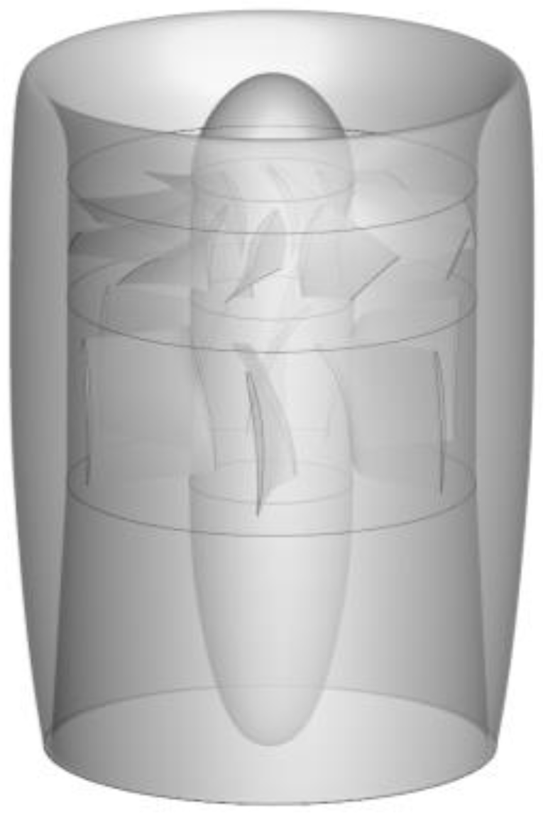
Funding

This research was funded by the Civil Aircraft Specific Project of China (MJ-2015-F-009), Shaanxi Provincial Key Research and Development Program (2021ZDLGY09-08), and Natural Science Basis Research Plan in Shaanxi Province of China (2022JQ-060).

Data Availability Statement

Not applicable.

Conflicts of Interest

The authors declare no conflict of interest.

References

  1. Black, D.; Rohrbach, C. Shrouded Propellers—A Comprehensive Performance Study. In Proceedings of the 5th Annual Meeting and Technical Display, Philadelphia, PA, USA, 21–24 October 1968. [Google Scholar] [CrossRef]
  2. Xu, H.; Ye, Z. Numerical simulation and comparison of aerodynamic characteristics between ducted and isolated propellers. J. Aerosp. Power 2011, 26, 2820–2825. [Google Scholar] [CrossRef]
  3. Liu, P. Theory and Application of Airscrew, 1st ed.; Beihang University Press: Beijing, China, 2006; pp. 90–92. [Google Scholar]
  4. Coney, W.B. A Method for the Design of a Class of Optimum Marine Propulsors. Ph.D. Dissertation, Massachusetts Institute of Technology, Cambridge, MA, USA, 1989. [Google Scholar]
  5. Kerwin, J.E.; Coney, W.B.; Hsin, C.Y. Optimum Circulation Distributions for Single and Multi-Component Propulsor. In Proceedings of the 21st American Towing Tank Conference, Washington, DC, USA, 5–7 August 1986. [Google Scholar]
  6. Stubblefield, J.M. Numerically-Based Ducted Propeller Design Using Vortex Lattice Lifting Line Theory. Master’s Thesis, Massachusetts Institute of Technology, Cambridge, MA, USA, 2008. [Google Scholar]
  7. Yang, Z.; Ma, Y.; Chen, Y. Integrated optimal design of ducted propeller based on DOE. Adv. Mater. Res. 2011, 291–294, 1698–1703. [Google Scholar] [CrossRef]
  8. Yu, L.; Drukenbrod, M.; Greve, M. Research on automatic optimization of ducted propeller design based on CFD techniques. Chin. J. Hydrodyn. 2013, 28, 438–444. [Google Scholar]
  9. Wang, H.; Wang, Y.; Zhou, F. Optimization design of inlet for distributed ducted fan propulsion system based on panel method. J. Propuls. Technol. 2021, 42, 2465–2473. [Google Scholar] [CrossRef]
  10. Xu, H.; Ye, Z. Numerical simulation of ducted-propeller system using unstructured overset grids. Acta Aerodyn. Sin. 2013, 31, 306–309. [Google Scholar]
  11. Echavarria, C.; Poroseva, S. Computational Analysis of the Blade Number Effect on the Performance of a Ducted Propeller. In Proceedings of the AIAA Atmospheric Flight Mechanics Conference, Kissimmee, FL, USA, 5–9 January 2015. [Google Scholar] [CrossRef] [Green Version]
  12. Wang, H.; Zhu, X.; Zhou, Z. Aerodynamic investigation on propeller slipstream flows for solar powered airplanes. J. Northwest. Polytech. Univ. 2015, 33, 910–920. [Google Scholar]
  13. Ahn, J.; Lee, K.T. Performance Prediction and Design of a Ducted Fan System. In Proceedings of the 40th AIAA/ASME/SAE/ASEE Joint Propulsion Conference and Exhibit, Fort Lauderdale, FL, USA, 11–14 July 2004. [Google Scholar] [CrossRef]
  14. Akturk, A.; Carried, C. Experimental and computational assessment of a ducted-fan rotor flow model. J. Aircr. 2012, 49, 885–897. [Google Scholar] [CrossRef]
  15. Rajagopalan, R.; Zhang, Z. Performance and Flow Field of a Ducted Propeller. In Proceedings of the 25th Joint Propulsion Conference, Monterey, CA, USA, 12–16 July 1989. [Google Scholar] [CrossRef]
  16. Chang, I.C.; Rajagopalan, R. CFD Analysis for Ducted Fans with Validation. In Proceedings of the 21st AIAA Applied Aerodynamics Conference, Orlando, FL, USA, 23–26 June 2003. [Google Scholar] [CrossRef] [Green Version]
  17. Song, C.; Lin, Y.; Chen, W. CFD analysis for the ducted tail rotor based on momentum source method. Helicopter Tech. 2009, 1, 6–11. [Google Scholar] [CrossRef]
  18. Ye, K.; Ye, Z.; Qu, Z. Aerodynamic optimization method for duct design. J. Aerosp. Power 2013, 28, 1828–1835. [Google Scholar]
  19. Ji, L.; Li, J.; Fang, Y. The aerodynamic characteristics and parameter optimization design of ducted fan. Sci. Technol. Eng. 2019, 19, 245–251. [Google Scholar]
  20. Han, Z. Kriging surrogate model and its application to design optimization: A review of recent progress. Acta Aeronaut. Astronaut. Sin. 2016, 37, 197–3225. [Google Scholar] [CrossRef]
Figure 1. Geometry of the 150 ducted fan.
Aerospace 09 00241 g001
Figure 2. Schematic diagram of the duct profile.
Aerospace 09 00241 g002
Figure 3. Experimental site and connection mode of the 150 ducted fan.
Aerospace 09 00241 g003
Figure 4. Diagram of rotor grids with different grid sizes: (a) 1.18 million, (b) 1.92 million, (c) 3.11 million.
Aerospace 09 00241 g004
Figure 5. Diagram of background grids with different grid sizes: (a) 1.04 million, (b) 1.65 million.
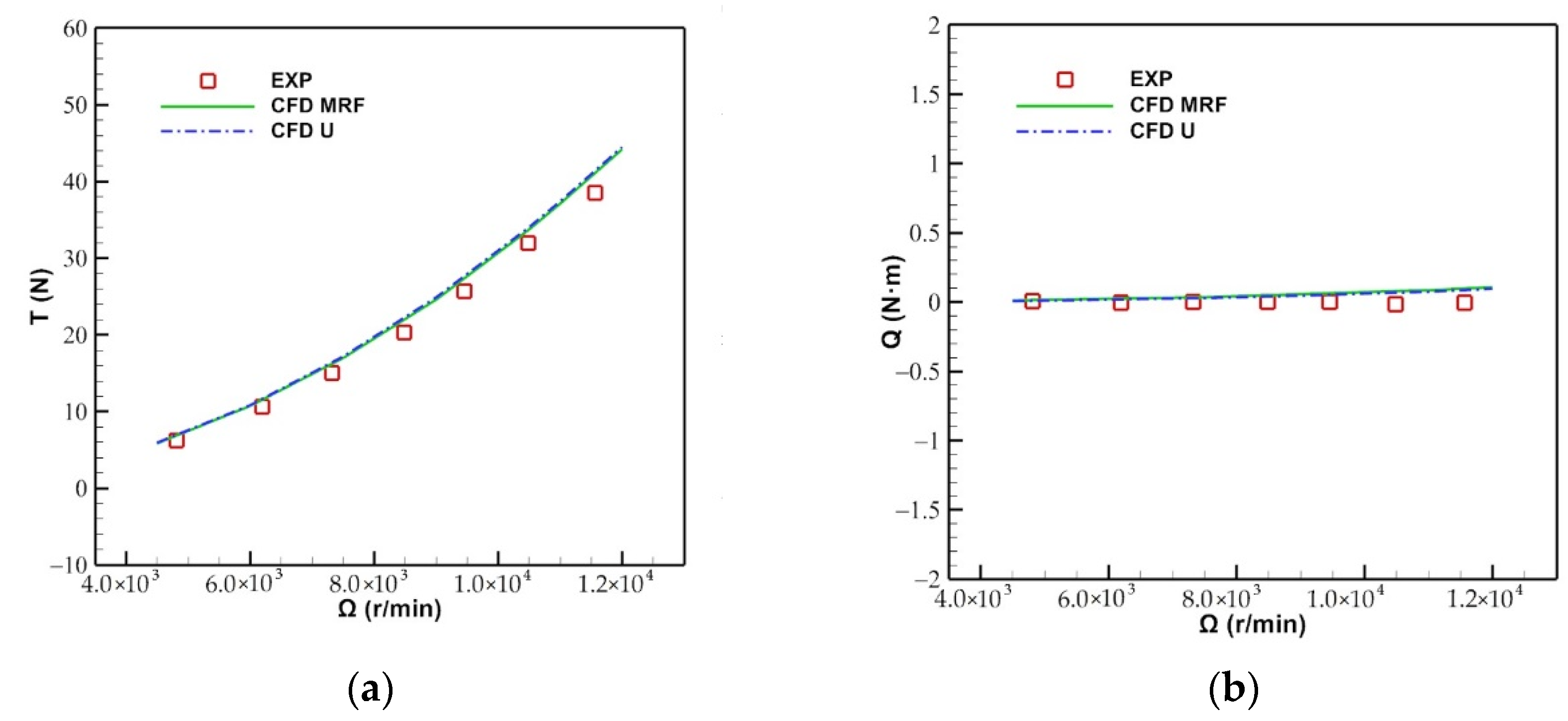
Aerospace 09 00241 g005
Figure 6. Comparison of the results between the experiment and CFD methods: (a) Total thrust, (b) total torque.
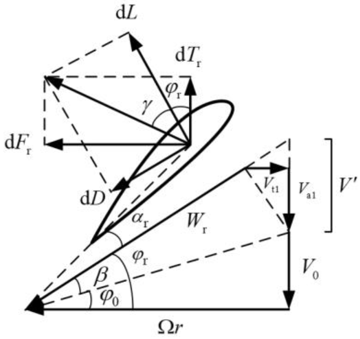
Aerospace 09 00241 g006
Figure 7. Schematic diagram of rotor element analysis.
Aerospace 09 00241 g007
Figure 8. Schematic diagram of the blade airfoil.
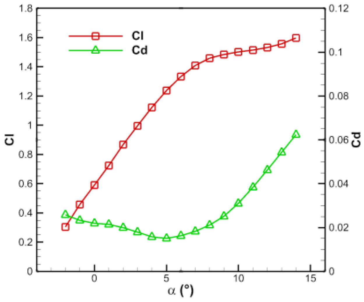
Aerospace 09 00241 g008
Figure 9. Aerodynamic curves of the stator.
Aerospace 09 00241 g009
Figure 10. Design results of the chord length and torsion angle of the blade: (a) Rotor, (b) stator.
Aerospace 09 00241 g010
Figure 11. Design process of the efficient blade design method.
Aerospace 09 00241 g011
Figure 12. Comparison of the chord length and torsion angle of the blade before and after the modification: (a) Rotor, (b) stator.
Aerospace 09 00241 g012
Figure 13. Design results of the chord length and torsion angle of the blade in the incoming flow state: (a) Rotor, (b) stator.
Aerospace 09 00241 g013
Figure 14. Schematic diagram of the duct profile of the 400 ducted fan.
Aerospace 09 00241 g014
Figure 15. Aerodynamic curves of the stator of the 400 ducted fan.
Aerospace 09 00241 g015
Figure 16. Results of the chord length and torsion angle of the blade of the 400 ducted fan: (a) Rotor, (b) stator.
Aerospace 09 00241 g016
Figure 17. Test picture of the 400 ducted fan.
Aerospace 09 00241 g017
Figure 18. Connection mode of the 400 ducted fan.
Aerospace 09 00241 g018
Figure 19. Comparison between the experimental results and CFD results of the 400 ducted fan: (a) Total thrust, (b) total torque.
Aerospace 09 00241 g019
Figure 20. Comparison of the chord length and torsion angle of the blade of the 400 ducted fan: (a) Rotor, (b) stator.
Aerospace 09 00241 g020
Table 1. Performance comparison of the ducted fan with different blade grids.
Grid Sizes (million)Ω (rpm)Tr (N)Qr (N·m)Ts (N)Qs (N·m)T (N)
1.1811,00014.1940.8832.8690.97337.042
1.9211,00014.3430.8852.9030.97137.107
3.1111,00014.2500.8782.8730.96037.013
Table 2. Performance comparison of the ducted fan with different background grids.
Grid Sizes (million)Ω (rpm)Tr (N)Qr (N·m)Ts (N)Qs (N·m)T (N)
1.0411,00014.3430.8852.9030.97137.013
1.6511,00014.4880.8872.9660.97237.334
Table 3. Performance comparison of the 150 ducted fan.
TypeTr (N)Qr (N·m)Ts (N)Qs (N·m)T (N)
Design14.9870.7991.7650.79937.000
MRF13.2830.7371.5430.67732.796
Table 4. Performance comparison of the 150 ducted fan before and after the modification.
ProcessTypeTr (N)Qr (N·m)Ts (N)Qs (N·m)T (N)
Initial designDesign14.9870.7991.7650.79937.000
MRF13.2830.7371.5430.67732.796
Modification 1Design14.9830.9042.0630.90437.000
MRF14.6580.8691.9390.82936.761
Modification 2Design14.7360.8761.8990.87637.000
MRF14.6470.8641.9340.85936.549
Modification 3Design14.8010.8791.9640.87937.000
MRF14.6870.8731.9600.87336.910
Table 5. Performance comparison of the 150 ducted fan in the incoming flow state.
TypeTr (N)Qr (N·m)Ts (N)Qs (N·m)T (N)
Design11.6520.7440.8190.74415.500
MRF11.5960.7390.8230.74115.273
Table 6. Performance comparison of the 400 ducted fan.
TypeTr (N)Qr (N·m)Ts (N)Qs (N·m)T (N)
Design112.4038.2433.2998.243200.000
MRF113.3148.3502.9678.465201.195
Table 7. Performance comparison of the redesigned 400 ducted fan.
TypeTr (N)Qr (N·m)Ts (N)Qs (N·m)T (N)
Design108.4997.9574.8817.957200.000
MRF108.3487.9554.8767.898199.315
Publisher’s Note: MDPI stays neutral with regard to jurisdictional claims in published maps and institutional affiliations.

