Abstract
In this paper, we present a highly linear direct in-phase/quadrature (I/Q) up-conversion mixer for 5G millimeter-wave applications. To enhance the linearity of the mixer, we propose a complementary derivative superposition technique with pre-distortion. The proposed up-conversion mixer consists of a quadrature generator, LO buffer amplifiers, and an I/Q up-conversion mixer core and achieves an output third-order intercept point of 15.7 dBm and an output 1 dB compression point of 2 dBm at 27.6 GHz, while it consumes 15 mW at a supply voltage of 1 V. The conversion gain is 11.4 dB and the LO leakage and image rejection ratio are −56 dBc and 61 dB, respectively, in the measurement. The proposed I/Q up-conversion mixer is suitable for 5G cellular communication systems.
1. Introduction
Recently, millimeter-wave (mm-wave) transceivers have been intensively researched for multi-Gb/s data transfer with low-latency and high reliability [1,2,3,4,5,6,7,8]. For fifth-generation (5G) cellular communications, n260 (37~40 GHz) and n257 (26.5~29.5 GHz) mm-wave bands are allocated for 5G applications [9,10,11]. Transceiver systems [1,2,3,4,5,6,7,8] have successfully demonstrated 5G cellular communications using mm-wave bands. The transceivers for mm-wave 5G cellular communications use phased arrays to enhance communication distance and coverage to non-line-of-sight propagation [5,6,7,8].
The direct conversion transceiver is popular since it reduces the power consumption and chip area. In the transmitter, one of the most important key blocks is the in-phase/quadrature (I/Q) direct up-conversion mixer. Local oscillator (LO) leakage and I/Q mismatch of the mixer severely degrade the error vector magnitude (EVM) performance. Moreover, a high linearity mixer is required for the minimum stages of the power amplifier to provide a small chip area and low DC power consumption.
Linearity enhancement techniques with a dual-gate mixer, an adaptive biasing circuit, inductive degeneration, and LO boosting linearization have been reported for a higher 1-dB compression point (P1dB) [12,13,14,15]; however, these techniques are limited by an output P1dB (OP1dB) of less than 0 dBm and hence limited by the third-order intercept point (IP3). To enhance IP3 performance of the up-conversion mixer, second-order intermodulation (IM2) injection and single stack transistor are used [16,17]. However, the IM2 injection degrades the conversion gain (CG) and the single-stack transistor consumes a huge amount of DC power from a large LO signal. Furthermore, the output IP3 (OIP3) is than 11 dBm. To suppress the LO leakage and enhance the CG and image rejection ratio (IRR), transformers and high-precision polyphase filters are used [18,19]. These up-conversion mixers provide high LO leakage and IRR, but the linearity performance is limited.
This paper presents a highly linear direct I/Q up-conversion mixer designed for 5G applications operating in the 28 GHz frequency band. The proposed mixer utilizes a symmetric layout for the mixer core and complementary derivative superposition (DS) technique with pre-distortion to improve IRR, LO leakage, and linearity. The proposed mixer was implemented in 65 nm CMOS. The mixer achieves an OP1dB of 2 dBm and an OIP3 of 15.7 dBm at 27.6 GHz with a DC power consumption of 15 mW from a supply voltage of 1 V. The CG is 11.4 dB and the IRR and LO leakage are 61 dB and −56 dBc, respectively. This article is an extended version of [20], with an in-depth analysis.
2. Design of I/Q Up-Conversion Mixer
Figure 1 shows the block diagram of the direct up-conversion mm-wave transmitter. This architecture is widely adopted due to the low DC power consumption and small chip area compared to the heterodyne architecture [21]. One of the most important building blocks in the transmitter is the I/Q up-conversion mixer. Figure 2 presents the simplified block diagram of the proposed up-conversion mixer. The proposed mixer consists of a quadrature generator, mixer core, and two LO amplifiers. The quadrature generator is integrated to provide 0°/90°/180°/270° signals to the LO inputs of the mixer. The gain and phase mismatches of the quadrature generator and mixer core cause I/Q imbalance and EVM degradation. EVM due to I/Q imbalance can be expressed as
where ϵ is the gain error and is the phase error.
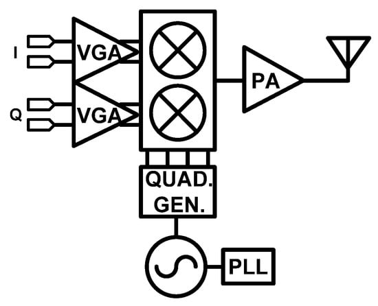
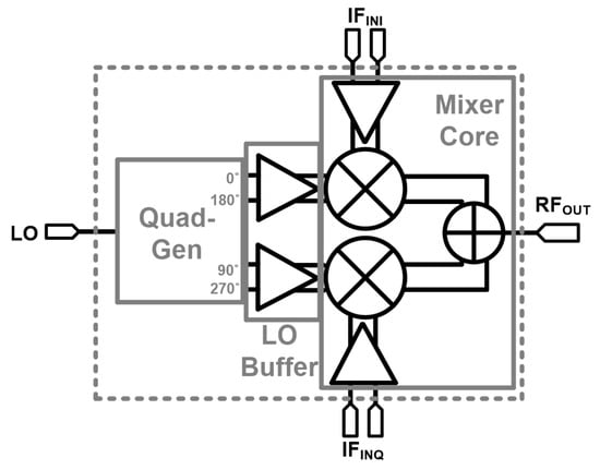
Figure 3 shows the quadrature generator, which consists of a 90° phase generator and two active baluns. The resistive power divider splits the power equally without gain and phase errors in a small chip area at the cost of a 3 dB loss. A high-pass/low-pass structure gives 90° phase difference. Active baluns generate differential signals and reduce amplitude and phase errors. Even though the resistive power divider, 90° phase generator and the active balun provide acute I/Q signal generation in the simulation, temperature and process variations limit the signal quality. To overcome this issue, phase tuning and amplitude tuning are introduced at the 90° phase generator and the active balun, respectively. In the 90° phase generator, a shunt capacitor bank and a varactor are used for coarse and fine tuning of the phase in the I-path, respectively, which provides continuous phase control of 18°. An active balun provides 6 dB gain control with 4 bit DAC. The active balun and the LO buffer amplifiers use differential common source amplifiers with inductive degeneration to provide fully differential outputs. The quadrature signals are generated at the quadrature generator and amplified by the LO buffer amplifiers to provide a 500 mVp-p voltage swing at the LO input port of the mixer from a −13 dBm LO input power.
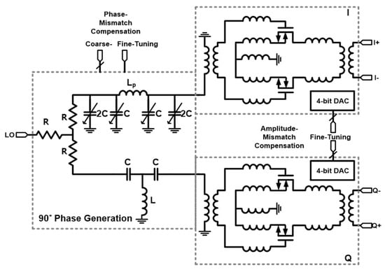
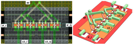
Figure 4 depicts the schematic of a mixer core and its intermodulation components in a two-tone test. To simultaneously achieve small LO leakage and high IRR, the mixer adopts the Gilbert-cell architecture. Unwanted mismatch of the layout degrades IRR and LO leakage performances. To minimize the LO leakage and IRR, the mixer core layout is set out in a symmetric way. Figure 5 shows the 2D and 3D layout for the switching stage of the mixer. The IF input is applied to the left and right sides with the two bottom metals and is isolated from the RF and LO signal lines using a ground middle metal. The output of the mixer core, RF, is obtained at the drain, on the top side, with the two top metals. LO inputs are connected to the gate of the switching stage, on the bottom side, with the top metal. As a result, the RF, LO, and IF signal lines are symmetric and they do not interfere each other, which enhances IRR and LO leakage performance.
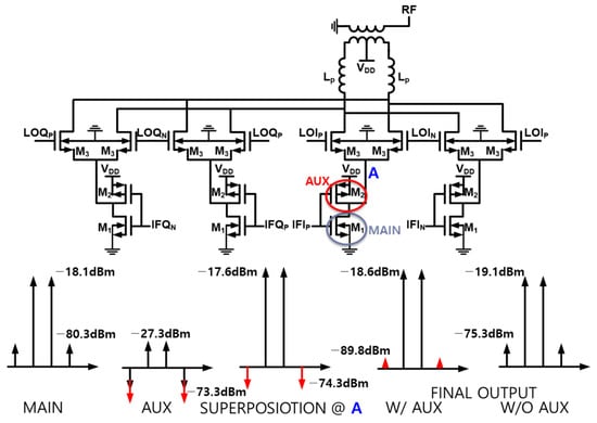
In the transmitter, we need a high-linearity mixer to reduce the power consumption and the chip area by using fewer power amplifier stages. The switching stage is the main source of non-linearity in the Gilbert-cell mixer. To enhance linearity, we employ a complementary DS technique with pre-distortion. We add an auxiliary (aux) transistor M2 to the main transistor M1. The complementary DS technique [22] removes the third-order derivatives, gm3, of the current at the drain depending on the input voltage of both transistors, resulting in high OIP3 performance. Unlike the low noise amplifier in [22], we use M2 to cancel out the gm3 of not only M1 but also M3 in Figure 4. Without additional current, M2 also pre-distorts gm3 to enhance the linearity by minimizing the gm3 of M3. Moreover, M2 adds a power gain of 0.5 dB and reduces output third-order intermodulation distortion from −75.3 to −89.8 dBm at the input of −30 dBm, as shown in Figure 4.
The proposed I/Q up-conversion mixer is designed for a center frequency of 28 GHz and employs inductors and transformers in the matching network for low loss and compact design. All inductors, transformers, and interconnections are designed and optimized with electromagnetic simulation. The proposed up-conversion mixer uses the complementary DS technique to improve the linearity, resulting in 4 dB higher OP1dB and 8 dB higher OIP3 than the mixer without M2 in Figure 4. The simulation results show that the mixer achieves a CG of 11.4 dB, a 3 dB bandwidth of 2.7 GHz, an OP1dB of 2 dBm and an OIP3 of 17 dBm.
3. Fabrication and Measurement
The proposed mixer was designed and implemented in 65 nm CMOS technology. Figure 6 depicts a microphotograph of the proposed up-conversion mixer. The core area of the mixer, including the pads, was 1.232 mm2. The up-conversion mixer core consumed 15 mW from a supply voltage of 1 V. The S-parameter, CG, P1dB, and OIP3 were measured on-wafer using ground–signal–ground and ground–signal–signal–ground probes. For the S-parameter measurement, the Keysight E8361A Vector Network Analyzer was used. As shown in Figure 7, CG, P1dB and OIP3 were measured with a signal generator, an arbitrary waveform generator (AWG) and a spectrum analyzer. In the measurement results, all losses of cables and probes were de-embedded.
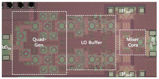
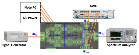
Figure 8 depicts the simulated and measured CG gain versus IF frequency of the proposed mixer. An input frequency of 28 GHz and an input power of −30 dBm were applied to LO and IF, respectively. A measured CG of 11.4 dB was achieved with −13 dBm LO input power and 400 MHz IF frequency. A 3 dB bandwidth of 2.2 GHz was measured. Output and input return losses higher than 10 dB were achieved for LO and RF frequencies of 26–30 GHz and an IF frequency of 0.1–3 GHz, respectively.
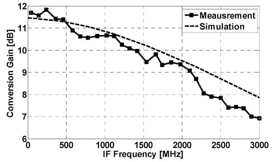
Figure 8.
Simulated and measured mixer conversion gain versus IF frequency: fLO = 28 GHz; PLO = −13 dBm; PIF = −30 dBm.
Figure 9 illustrates the measured and simulated CG of the proposed mixer with LO input power. The LO and IF frequencies were 28 GHz and 400 MHz, respectively, and an input power of −30 dBm was applied. A CG of 11.4 dB was measured at −13 dBm LO input power. Figure 10 shows the simulated and measured CG of the mixer with IF input power. The LO and IF frequencies were 28 GHz and 400 MHz, respectively. The measured OP1dB of the mixer was 2 dBm at −13 dBm LO input power.
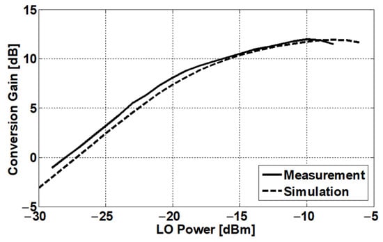
Figure 9.
Measured and simulated conversion gain of mixer with respect to LO power: fLO = 28 GHz; fIF = 400 MHz; PIF = −30 dBm.
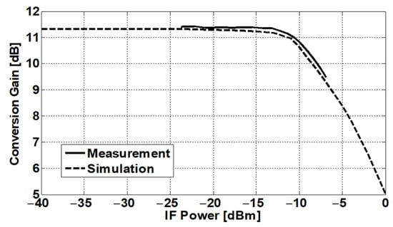
Figure 10.
Measured and simulated conversion gain of mixer with respect to IF power: fLO = 28 GHz; fIF = 400 MHz; PLO = −13 dBm.
Figure 11 shows the simulated and measured OIP3 with the input gate voltage and LO input power. Figure 12 depicts the measured output spectrum. The IF input gates of the mixer were biased at 0.53 V. An input power of −13 dBm with a frequency of 28 GHz was applied to LO and frequencies of 390 MHz and 400 MHz were selected for IF. An OIP3 of 15.7 dBm was measured. Figure 13 shows the measured output spectrum for the LO leakage and IRR test with 10 MHz IF frequency. The LO input power is −13 dBm at 28 GHz. The mixer achieved 61 dB IRR and −56 dBc LO leakage from a symmetrical-layout and accurate quadrature generator.
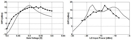
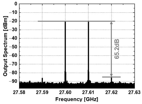
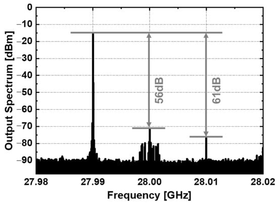
Figure 13.
Measured output spectrum for LO leakage and IRR: fLO = 28 GHz; fIF = 10 MHz; PLO = −13 dBm.
Table 1 compares the performance of several K-/Ka-band up-conversion mixers. To compare the overall performance of the mixers in Table 1, a figure of merit (FoM) [18], defined as
was employed.

The proposed mixer, which uses the pre-distorted complementary DS technique, symmetric layout, and phase/amplitude control, achieved a higher OIP3 of 15.7 dBm, a higher OP1dB of 2 dBm, a higher CG of 11.4 dB, a lower LO leakage of −56 dBc, and a higher IRR of 61 dB than other works. As a result, the proposed mixer achieved higher FoM compared with other works in Table 1. The measurement results show that this work is suitable for 5G cellular communications.
4. Conclusions
In this paper, we present a highly linear direct I/Q up-converter that was implemented in 65 nm CMOS technology. The proposed mixer utilizes a pre-distorted complementary DS technique, symmetric layout, and phase/amplitude control to enhance the linearity, LO leakage, and IRR performances. With this architecture, the proposed I/Q up-converter achieved a low LO leakage of −56 dBc, a high OIP3 of 15.7 dBm, and a high IRR of 61 dB at a DC power consumption of 15 mW, which proves that this work is suitable for 5G cellular communications.
Funding
This work was supported by the National Research Foundation of Korea (NRF) grant funded by the Korea government (MSIT) (No. 2022R1C1C1011447).
Institutional Review Board Statement
Not applicable.
Informed Consent Statement
Not applicable.
Data Availability Statement
Data is contained within this article.
Conflicts of Interest
The author declare no conflict of interest.
References
- Roh, W.; Seol, J.-Y.; Park, J.H.; Lee, B.; Lee, J.; Kim, Y.; Cho, J.; Aryanfa, F.; Cheun, K. Millimeter-Wave Beamforming as an Enabling Technology for 5G Cellular Communications: Theoretical Feasibility and Prototype Results. IEEE Commun. Mag. 2014, 52, 106–113. [Google Scholar] [CrossRef]
- Byeon, C.W.; Yoon, C.H.; Park, C.S. A 67-mW 10.7-Gb/s 60-GHz OOK CMOS transceiver for short-range wireless communications. IEEE Trans. Microw. Theory Tech. 2013, 61, 3391–3401. [Google Scholar] [CrossRef]
- Byeon, C.W.; Eun, K.C.; Park, C.S. A 2.65-pJ/Bit 12.5-Gb/s 60-GHz OOK CMOS Transmitter and Receiver for Proximity Communications. IEEE Trans. Microw. Theory Tech. 2020, 68, 2902–2910. [Google Scholar] [CrossRef]
- Huang, M.-Y.; Chi, T.; Li, S.; Huang, T.-Y.; Wang, H. A 24.5–43.5-GHz ultra-compact CMOS receiver front end with calibration-free instantaneous full-band image rejection for multiband 5G massive MIMO. IEEE J. Solid-State Circuits 2020, 55, 1177–1186. [Google Scholar] [CrossRef]
- Yin, Y.; Ustundag, B.; Kibaroglu, K.; Sayginer, M.; Rebeiz, G.M. Wideband 23.5–29.5-GHz phased arrays for multistandard 5G applications and carrier aggregation. IEEE Trans. Microw. Theory Tech. 2021, 69, 235–247. [Google Scholar] [CrossRef]
- Jung, J.; Lee, J.; Kang, D.; Kim, J.; Lee, W.; Oh, H.; Park, J.; Kim, K.; Lee, D.; Lee, S.; et al. A 39 GHz 2 × 16-Channel Phased-Array Transceiver IC with Compact, High-Efficiency Doherty Power Amplifiers. In Proceedings of the 2023 IEEE Radio Frequency Integrated Circuits Symposium (RFIC), San Diego, CA, USA, 11–13 June 2023; pp. 273–276. [Google Scholar]
- Li, Z.; Pang, J.; Zhang, Y.; Yamazaki, Y.; Wang, Q.; Luo, P.; Chen, W.; Liao, Y.; Tang, M.; Wang, Y.; et al. A 39-GHz CMOS Bidirectional Doherty Phased- Array Beamformer Using Shared-LUT DPD with Inter-Element Mismatch Compensation Technique for 5G Base Station. IEEE J. Solid-State Circuits 2023, 58, 901–914. [Google Scholar] [CrossRef]
- Park, J.; Lee, S.; Chun, J.; Jeon, L.; Hong, S. A 28-GHz Four-Channel Beamforming Front-End IC with Dual-Vector Variable Gain Phase Shifters for 64-Element Phased Array Antenna Module. IEEE J. Solid-State Circuits 2023, 58, 1142–1159. [Google Scholar] [CrossRef]
- Song, J.-H.; Lee, E.-G.; Lee, J.-E.; Son, J.-T.; Kim, J.-H.; Baek, M.-S.; Kim, C.-Y. A 37–40 GHz 6-Bits Switched-Filter Phase Shifter Using 150 nm GaN HEMT. Nanomaterials 2023, 13, 2752. [Google Scholar] [CrossRef] [PubMed]
- Kiani, S.H.; Altaf, A.; Anjum, M.R.; Afridi, S.; Arain, Z.A.; Anwar, S.; Khan, S.; Alibakhshikenari, M.; Lalbakhsh, A.; Khan, M.A.; et al. MIMO Antenna System for Modern 5G Handheld Devices with Healthcare and High Rate Delivery. Sensors 2021, 21, 7415. [Google Scholar] [CrossRef] [PubMed]
- Hussain, S.A.; Taher, F.; Alzaidi, M.S.; Hussain, I.; Ghoniem, R.M.; Sree, M.F.A.; Lalbakhsh, A.L. Wideband, High-Gain, and Compact Four-Port MIMO Antenna for Future 5G Devices Operating over Ka-Band Spectrum. Appl. Sci. 2023, 13, 4380. [Google Scholar] [CrossRef]
- Verma, A.; O, K.K.; Lin, J. A low-power up-conversion CMOS mixer for 22–29-GHz ultra-wideband applications. IEEE Trans. Microw. Theory Tech. 2006, 54, 3295–3300. [Google Scholar] [CrossRef]
- Won, Y.-S.; Kim, C.-H.; Lee, S.-G. A 24 GHz highly linear up-conversion mixer in CMOS 0.13 μm technology. IEEE Microw. Wirel. Compon. Lett. 2015, 25, 400–402. [Google Scholar] [CrossRef]
- Lee, H.-S.; Min, B.-W. Ka-band up-conversion mixer with inductive degeneration. In Proceedings of the 2017 IEEE International Symposium on Radio-Frequency Integration Technology (RFIT), Seoul, Republic of Korea, 30 August–1 September 2017; pp. 211–213. [Google Scholar]
- Tsai, J.-H.; Hsieh, Y.-Y.; Liu, W.-H. A 27–44 GHz CMOS Dual-Ring Subharmonic Up-Conversion Mixer with Linearization Technique. IEEE Microw. Wirel. Compon. Lett. 2022, 32, 347–350. [Google Scholar] [CrossRef]
- Wang, Z.-H.; Chen, C.-N.; Huang, T.-W.; Wang, H. A 28-GHz high linearity up-conversion mixer using second-harmonic injection technique in 28-nm CMOS technology. IEEE Microw. Wirel. Compon. Lett. 2021, 31, 276–279. [Google Scholar] [CrossRef]
- Bae, B.; Jeong, J.; Kim, S.; Lee, J.; Kwon, K.; Han, J. 24–40 GHz Dual-Band Highly Linear CMOS Up-Conversion Mixer for mmWave 5G NR FR2 Cellular Applications. IEEE Microw. Wirel. Compon. Lett. 2022, 32, 999–1002. [Google Scholar] [CrossRef]
- Lee, S.; Jeon, Y.; Yoon, D.-Y.; Lee, O.; Im, D.; Nam, I. 28-GHz CMOS Up-Conversion Mixer with Improved LO Second-Harmonic Leakage Signal Suppression for 5G Applications. IEEE Access 2022, 10, 57003–57011. [Google Scholar] [CrossRef]
- Hu, K.; Ma, K.; Ma, Z. An Ultra-Wideband Image-Reject Up-Conversion Mixer with a Sandwich-Coupled Transformer for 5G mm-Wave Communication. IEEE Microw. Wirel. Compon. Lett. 2022, 32, 1099–1102. [Google Scholar] [CrossRef]
- Byeon, C.W.; Lee, J.H.; Lee, D.Y.; Kim, M.-R.; Son, J.H. A high linearity, image/LO-rejection I/Q up-conversion mixer for 5G cellular communications. In Proceedings of the 2015 10th European Microwave Integrated Circuits Conference (EuMIC), Paris, France, 7–8 September 2015; pp. 345–348. [Google Scholar]
- Kim, S.H.; Jang, T.H.; Kang, D.M.; Jung, K.P.; Park, C.S. Wideband 120-GHz CMOS I/Q Transmitter with Suppressed IMRR and LOFT for Wireless Short-Range High-Speed 6G IoT Applications. IEEE Internet Things J. 2023, 10, 11739–11748. [Google Scholar] [CrossRef]
- Im, D.; Nam, I.; Kim, H.; Lee, K. A Wideband CMOS Low Noise Amplifier Employing Noise and IM2 Distortion Cancellation for a Digital TV Tuner. IEEE J. Solid-State Circuits 2009, 44, 686–698. [Google Scholar] [CrossRef]
Disclaimer/Publisher’s Note: The statements, opinions and data contained in all publications are solely those of the individual author(s) and contributor(s) and not of MDPI and/or the editor(s). MDPI and/or the editor(s) disclaim responsibility for any injury to people or property resulting from any ideas, methods, instructions or products referred to in the content. |
© 2024 by the author. Licensee MDPI, Basel, Switzerland. This article is an open access article distributed under the terms and conditions of the Creative Commons Attribution (CC BY) license (https://creativecommons.org/licenses/by/4.0/).