

Development of a Body Weight Support System Employing Model-Based System Engineering Methodology

Abstract
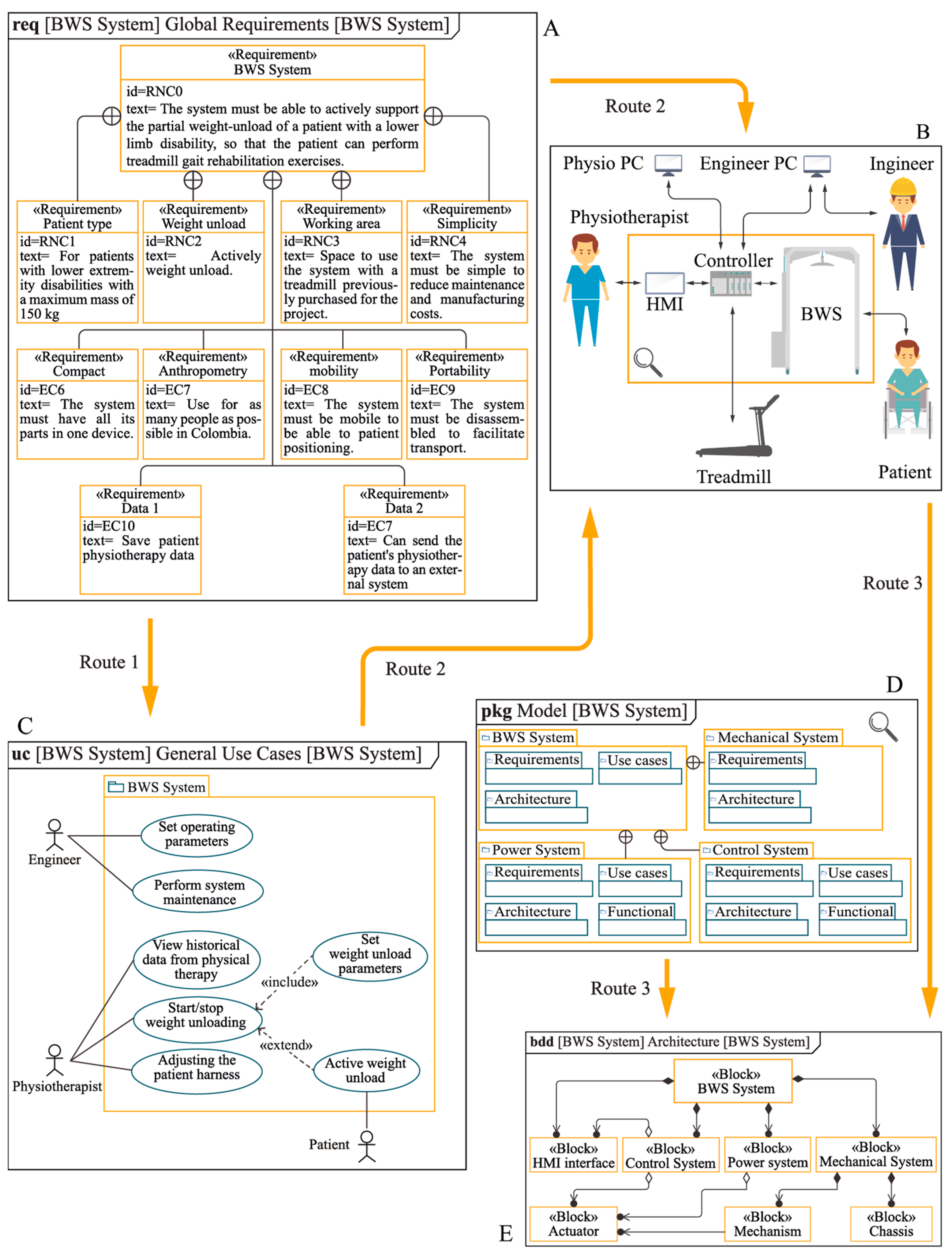
:1. Introduction
2. Materials and Methods
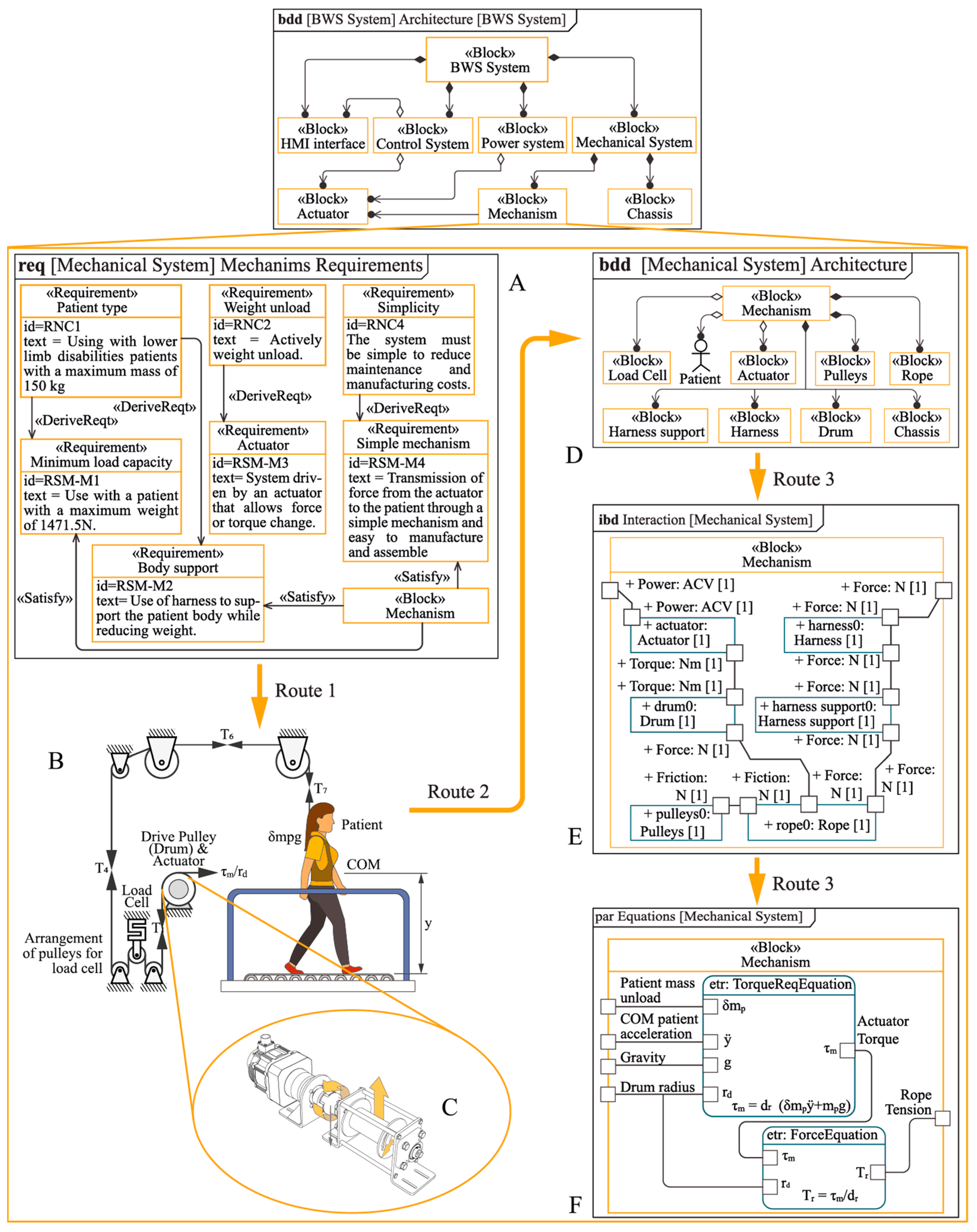
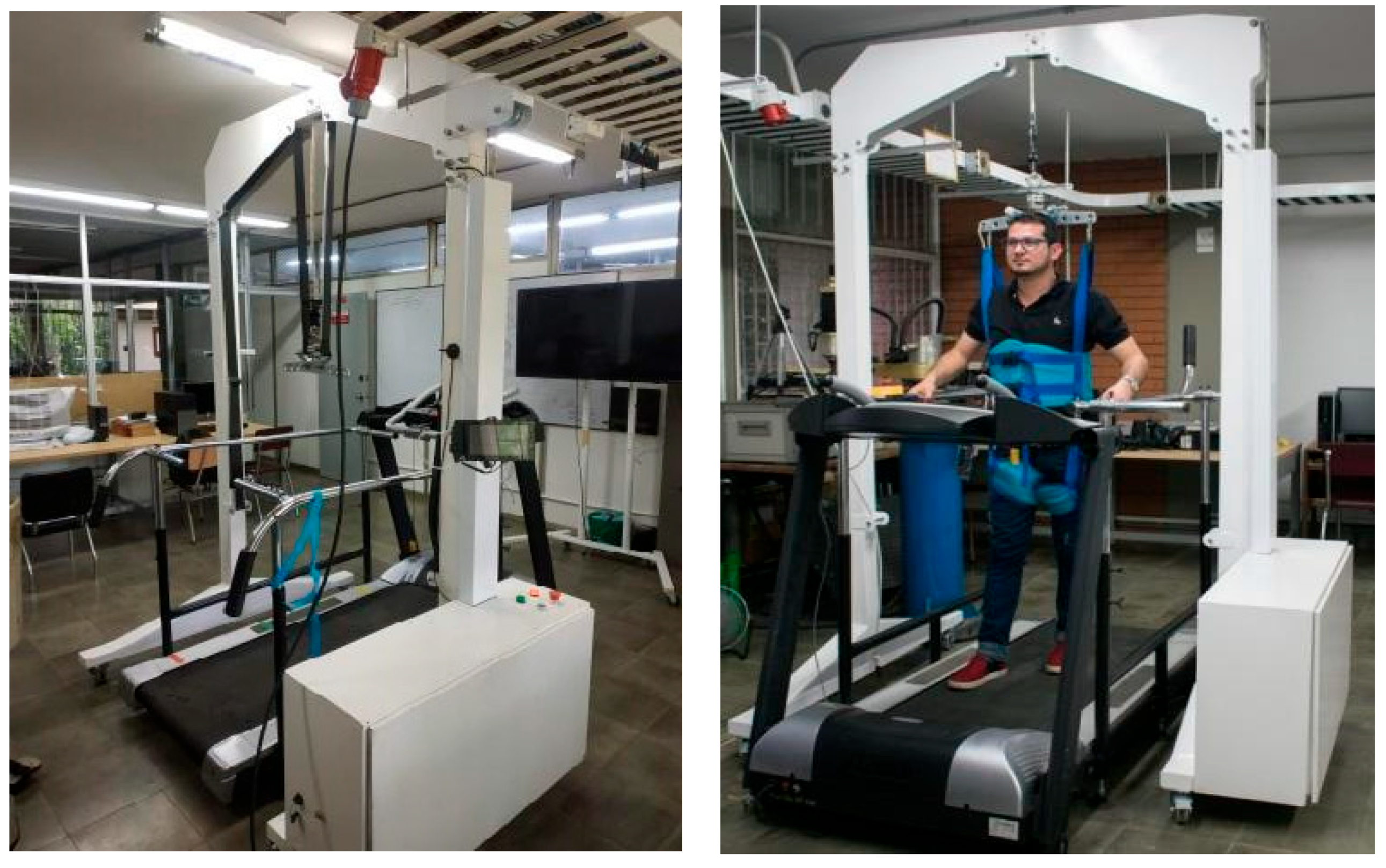
3. Mechanical System
3.1. Mechanism
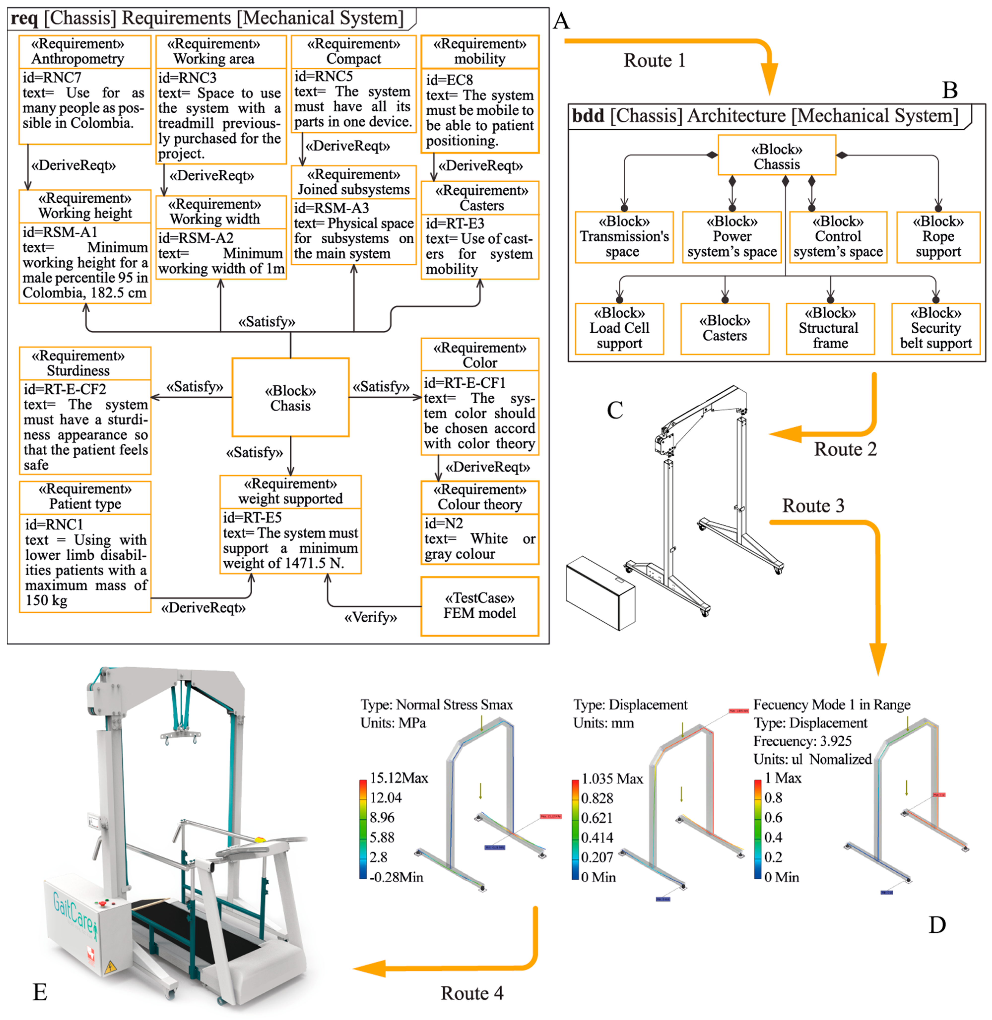
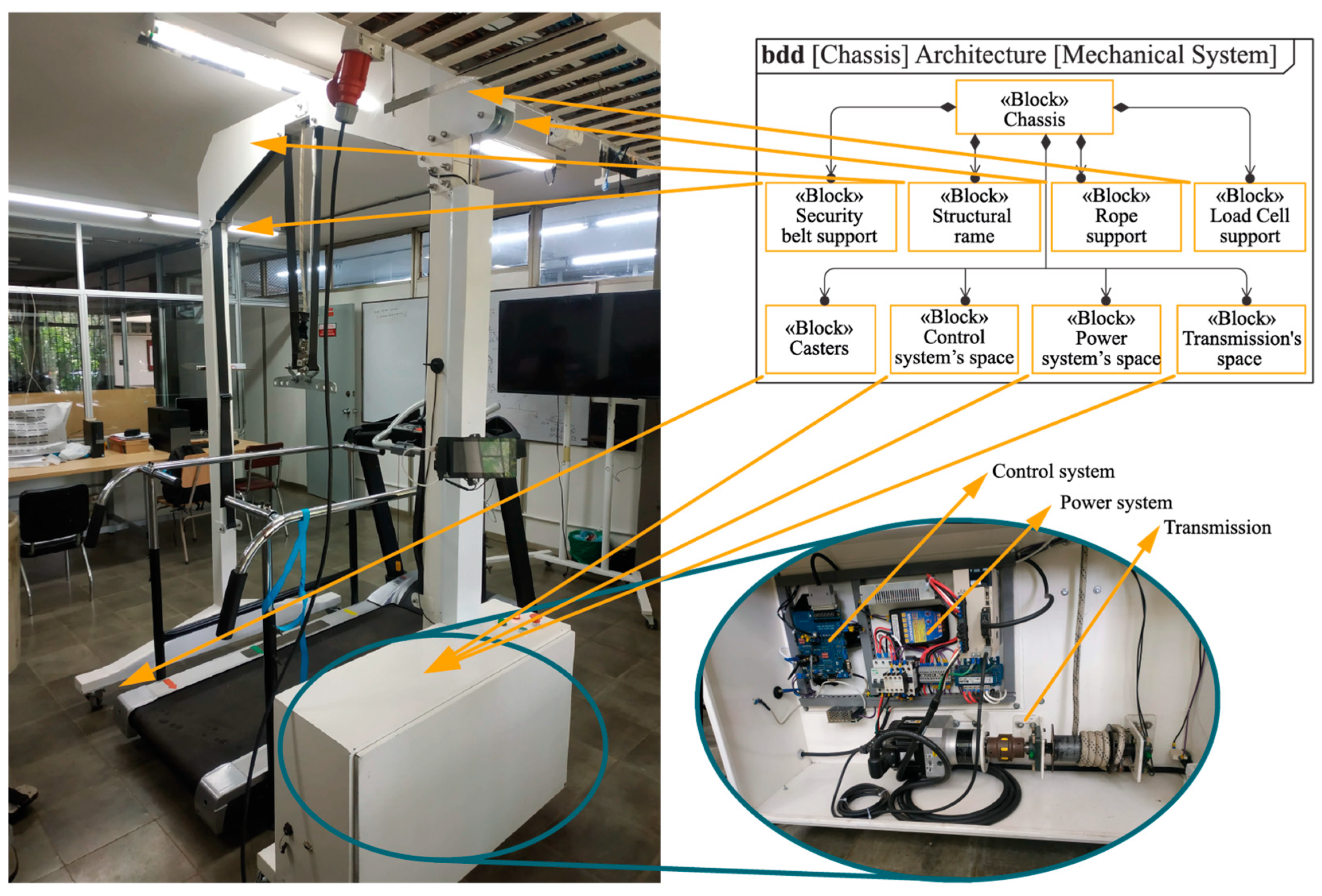
3.2. Chassis
4. Power System
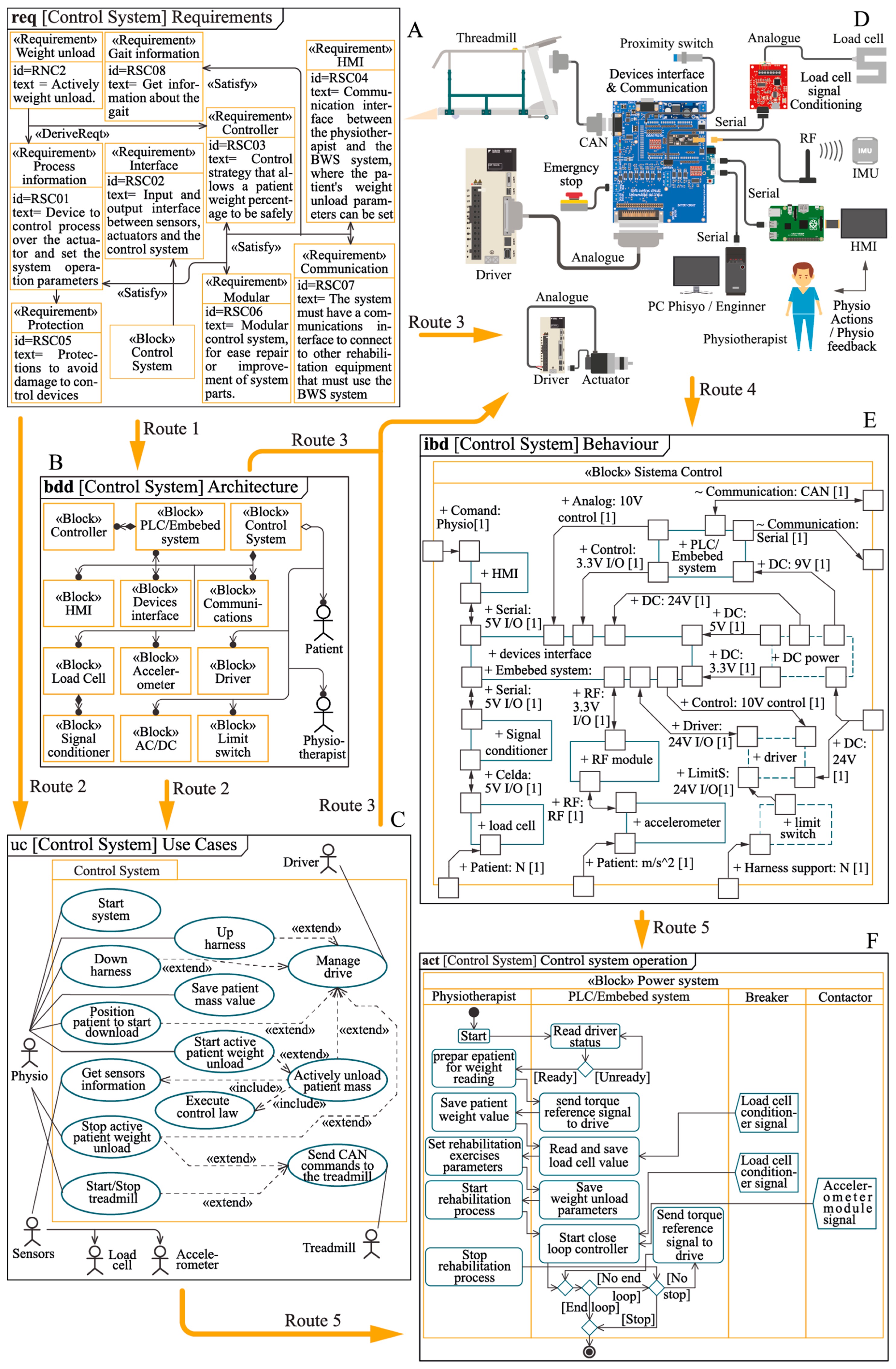
5. Control System
6. Results
7. Conclusions
Author Contributions
Funding
Institutional Review Board Statement
Informed Consent Statement
Data Availability Statement
Acknowledgments
Conflicts of Interest
References
- World Report on Disability. 2011. Available online: https://www.who.int/teams/noncommunicable-diseases/disability-and-rehabilitation/world-report-on-disability (accessed on 13 July 2023).
- Callaway, C.W.; Carson, A.P.; Chamberlain, A.M.; Chang, A.R.; Knutson, K.L.; Lewis, T.T.; Lichtman, J.H.; Loop, M.S.; Lutsey, P.L.; Spartano, N.L. Heart Disease and Stroke Statistics—2020 Update A Report from the American Heart Association. Circulation 2020, 141, 354–399. [Google Scholar] [CrossRef]
- Ma, V.Y.; Chan, L.; Carruthers, K.J. Incidence, Prevalence, Costs, and Impact on Disability of Common Conditions Requiring Rehabilitation in the United States: Stroke, Spinal Cord Injury, Traumatic Brain Injury, Multiple Sclerosis, Osteoarthritis, Rheumatoid Arthritis, Limb Loss. Arch. Phys. Med. Rehabil. 2014, 95, 986–995.e1. [Google Scholar] [CrossRef] [PubMed]
- Weerdesteyn, V.; De Niet, M.; Van Duijnhoven, H.J.R.; Geurts, A.C.H. Falls in Individuals with Stroke. J. Rehabil. Res. Dev. 2008, 45, 1195–1214. [Google Scholar] [CrossRef]
- Kwakman, R.C.H.; Sommers, J.; Horn, J.; Nollet, F.; Engelbert, R.H.H. Steps to Recovery: Body Weight-Supported Treadmill Training for Critically Ill Patients: A Randomized Controlled Trial. Trials 2020, 21, 409. [Google Scholar] [CrossRef]
- Bannwart, M.; Rohland, E.; Easthope, C.A.; Rauter, G.; Bolliger, M. Robotic Body Weight Support Enables Safe Stair Negotiation in Compliance with Basic Locomotor Principles. J. Neuroeng. Rehabil. 2019, 16, 157. [Google Scholar] [CrossRef]
- Brunelli, S.; Iosa, M.; Romana, F.; Pirri, C.; Di, C.; Foti, C.; Traballesi, M.; Index, M.; Index, B.; Test, W. Early Body Weight-Supported Overground Walking Training in Patients with Stroke in Subacute Phase Compared to Conventional Physiotherapy: A Randomized Controlled Pilot Study. Int. J. Rehabil. Res. 2019, 42, 309–315. [Google Scholar] [CrossRef] [PubMed]
- Barela, A.; Gama, G.L.; Celestino, M.L.; Forrester, L.; Whitall, J.; Barela, A.M. Effects of Gait Training with Body Weight Support on a Treadmill Versus Overground in Individuals with Stroke. Arch. Phys. Med. Rehabil. 2017, 98, 738–745. [Google Scholar] [CrossRef]
- Cacciola, A.; Berte, F.; Manuli, A.; Leo, A.; Bramanti, A.; Naro, A. Robotic Gait Rehabilitation and Substitution Devices in Neurological Disorders: Where Are We Now? Neurol. Sci. 2016, 37, 503–514. [Google Scholar] [CrossRef]
- Ryoul, K.; Su, M.; Lim, B.; Guo, Z.; Yu, H. Biomechanical Effects of Body Weight Support with a Novel Robotic Walker for over—Ground Gait Rehabilitation. Med. Biol. Eng. Comput. 2016, 55, 315–326. [Google Scholar] [CrossRef]
- Hurt, C.P.; Burgess, J.K.; Brown, D.A. Gait & Posture Limb Contribution to Increased Self-Selected Walking Speeds during Body Weight Support in Individuals Poststroke. Gait Posture 2015, 41, 857–859. [Google Scholar] [CrossRef]
- Park, B.-S.; Kim, M.-Y.; Lee, L.-K.; Yang, S.-M.; Lee, W.-D.; Noh, J.-W.; Shin, Y.-S.; Kim, J.-H.; Lee, J.-U.; Kwak, T.-Y.; et al. Effects of Conventional Overground Gait Training and a Gait Trainer with Partial Body Weight Support on Spatiotemporal Gait Parameters of Patients after Stroke. J. Phys. Ther. Sci. 2015, 27, 1603–1607. [Google Scholar] [CrossRef]
- Lam, T.; Pauhl, K.; Ferguson, A.; Malik, R.N.; Krassioukov, A.; Eng, J.J. Training with Robot-Applied Resistance in People with Motor-Incomplete Spinal Cord Injury: Pilot Study. J. Rehabil. Res. Dev. 2015, 52, 113–130. [Google Scholar] [CrossRef] [PubMed]
- Winstein, C.J.; Stein, J.; Arena, R.; Bates, B.; Cherney, L.R.; Cramer, S.C.; Deruyter, F.; Eng, J.J.; Fisher, B.; Harvey, R.L.; et al. Guidelines for Adult Stroke Rehabilitation and Recovery: A Guideline for Healthcare Professionals from the American Heart Association; American Stroke Association: Dallas, TX, USA, 2016; Volume 47. [Google Scholar] [CrossRef]
- Kratky, S.; Buchecker, M.; Pfusterschmied, J.; Szekely, C.; Müller, E. Effects of a Body-Weight Supporting Kite on Sprint Running Kinematics in Well-Trained Sprinters. J. Strength. Cond. Res. 2016, 30, 102–108. [Google Scholar] [CrossRef] [PubMed]
- McNeill, D.K.P.; de Heer, H.D.; Williams, C.P.; Coast, J.R. Metabolic Accommodation to Running on a Body Weight-Supported Treadmill. Eur. J. Appl. Physiol. 2015, 115, 905–910. [Google Scholar] [CrossRef] [PubMed]
- Neal, M.; Fleming, N.; Eberman, L.; Games, K.; Vaughan, J. Effect of Body-Weight-Support Running on Lower-Limb Biomechanics. J. Orthop. Sports Phys. Ther. 2016, 46, 784–793. [Google Scholar] [CrossRef] [PubMed]
- Sandrini, G.; Tassorelli, C.; Berra, E.; De Icco, R. Cues and Body-Weight-Supported (BWS) Gait Training in Parkinson’s Disease. In Advanced Technologies for the Rehabilitation of Gait and Balance Disorders. Biosystems & Biorobotics; Sandrini, G., Volker, H., Saltuari, L., Smania, N., Pedrocchi, A., Eds.; Springer: Cham, Switzerland, 2018; Volume 19, pp. 357–366. ISBN 9783319727363. [Google Scholar]
- Odin, A.; Faletto-Passy, D.; Assaban, F.; Pérennou, D. Modulating the Internal Model of Verticality by Virtual Reality and Body-Weight Support Walking: A Pilot Study. Ann. Phys. Rehabil. Med. 2018, 61, 292–299. [Google Scholar] [CrossRef] [PubMed]
- Huang, S.; Yu, X.; Lu, Y.; Qiao, J.; Wang, H.; Jiang, L.; Wu, X.; Niu, W. Body Weight Support-Tai Chi Footwork for Balance of Stroke Survivors with Fear of Falling: A Pilot Randomized Controlled Trial. Complement. Ther. Clin. Pr. 2019, 37, 140–147. [Google Scholar] [CrossRef] [PubMed]
- Tamai, K.; Kawamoto, H.; Sankai, Y. Weight-Supported Walking Assist Device for Knee Osteoarthritis Patients. In Proceedings of the 2019 IEEE 16th International Conference on Rehabilitation Robotics (ICORR), Toronto, ON, Canada, 24–28 June 2019; pp. 374–379. [Google Scholar]
- Ye, J.; Chen, G.; Liu, Q.; Duan, L.; Shang, W.; Yao, X.; Wang, Y.; Wu, Z.; Wang, C. An Adaptive Shared Control of a Novel Robotic Walker for Gait Rehabilitation of Stroke Patients. In Proceedings of the 2018 IEEE International Conference on Intelligence and Safety for Robotics (ISR), Shenyang, China, 24–27 August 2018; pp. 373–378. [Google Scholar]
- Sun, Y.; Lei, Y.; Zou, W.; Li, J.; Yu, N. Real-Time Force Control of an SEA-Based Body Weight Support Unit with the 2-DOF Control Structure. In Proceedings of the 2018 IEEE International Conference on Real-Time Computing and Robotics, RCAR 2018, Kandima, Maldives, 1–5 August 2018; pp. 390–394. [Google Scholar]
- Takiguchi, R.; Tran, V.; Yamamoto, S. Validation of the Novel Body Weight Support System Using Pneumatic Artificial Muscle: A Case Study. In Proceedings of the World Congress on Medical Physics and Biomedical Engineering 2018, IFMBE Proceedings, Prague, Czech Republic, 3–8 June 2018; Lhotska, L., Sukupova, L., Lacković, I., Ibbott, G., Eds.; Springer: Singapore, 2019; Volume 68, pp. 641–647. [Google Scholar]
- Kim, J.; Oh, S.; Kim, J.; Kim, J. A Two-Wire Body Weight Support System for Interactive Treadmill. In Proceedings of the 2019 IEEE 16th International Conference on Rehabilitation Robotics (ICORR), Toronto, ON, Canada, 24–28 June 2019; pp. 349–354. [Google Scholar]
- Moghadam, M.M. Conceptual Design of an Active Body Weight Support System Using a Linear Series Elastic Actuator. In Proceedings of the 2019 7th International Conference on Robotics and Mechatronics (ICRoM), Tehran, Iran, 20–21 November 2019; pp. 80–85. [Google Scholar]
- Song, Z.; Chen, W.; Wang, W.; Zhang, G. Dynamic Modeling and Simulation of a Body Weight Support System. J. Health Eng. 2020, 2020, 2802574. [Google Scholar] [CrossRef] [PubMed]
- Lv, G.; Gregg, R.D. Orthotic Body-Weight Support through Underactuated Potential Energy Shaping with Contact Constraints. In Proceedings of the IEEE Conference on Decision and Control, Osaka, Japan, 15–18 December 2015; pp. 1483–1490. [Google Scholar]
- Lu, Q.; Liang, J.; Qiao, B.; Ma, O. A New Active Body Weight Support System Capable of Virtually Offloading Partial Body Mass. IEEE/ASME Trans. Mechatron. 2013, 18, 11–20. [Google Scholar] [CrossRef]
- Pennycott, A.; Wyss, D.; Vallery, H.; Riener, R. Effects of Added Inertia and Body Weight Support on Lateral Balance Control during Walking. In Proceedings of the IEEE International Conference on Rehabilitation Robotics, Zurich, Switzerland, 29 June–1 July 2011; pp. 27–31. [Google Scholar]
- Mat Dzahir, M.A.; Nobutomo, T.; Yamamoto, S.I. Development of Body Weight Support Gait Training System Using Pneumatic Mckibben Actuators -Control of Lower Extremity Orthosis-. In Proceedings of the 2013 35th Annual International Conference of the IEEE Engineering in Medicine and Biology Society (EMBS), Osaka, Japan, 3–7 July 2013; pp. 6417–6420. [Google Scholar]
- Jung, S.; Kang, S.; Cho, H.; Kim, G.; Ryu, J.; Mun, M.; Moon, I. Modeling of Body Weight Support System for Person with Gait Disoder. In Proceedings of the 2013 4th International Conference on Intelligent Systems, Modelling and Simulation (ISMS), Bangkok, Thailand, 29–31 January 2013; pp. 172–176. [Google Scholar]
- Vallery, H.; Lutz, P.; von Zitzewitz, J.; Rauter, G.; Fritschi, M.; Everarts, C.; Ronsse, R.; Curt, A.E.P.; Bolliger, M. Multidirectional Transparent Support for Overground Gait Training. In Proceedings of the 2013 IEEE 13th International Conference on Rehabilitation Robotics (ICORR), Seattle, WA, USA, 24–26 June 2013; pp. 1–7. [Google Scholar]
- Wyss, D.; Bartenbach, V.; Pennycott, A.; Riener, R.; Vallery, H. A Body Weight Support System Extension to Control Lateral Forces: Realization and Validation. In Proceedings of the 2014 IEEE International Conference on Robotics and Automation (ICRA), Hong Kong, China, 31 May–7 June 2014; pp. 328–332. [Google Scholar] [CrossRef]
- Yang, Z.; Sun, Y.; Hao, Y.; Yu, N. Active Mass-Offloading with Cable-Driven SEA for Tailored Support to Lower Limb Rehabilitation. In Proceedings of the ICARM 2016—2016 International Conference on Advanced Robotics and Mechatronics, Macau, China, 18–20 August 2016; pp. 202–206. [Google Scholar]
- Sariyildiz, E.; Cheng, H.; Yagli, G.M.; Yu, H. Modelling and Control of a Novel Walker Robot for Post-Stroke Gait Rehabilitation. In Proceedings of the IECON 2017—43rd Annual Conference of the IEEE Industrial Electronics Society, Beijing, China, 29 October–1 November 2017; pp. 5221–5226. [Google Scholar]
- Wang, D.; Lee, K.-M.; Ji, J. A Passive Gait-Based Weight-Support Lower Extremity Exoskeleton with Compliant Joints. IEEE Trans. Robot. 2016, 32, 933–942. [Google Scholar] [CrossRef]
- Collo, A.; Bonnet, V.; Venture, G. A Quasi-Passive Lower Limb Exoskeleton for Partial Body Weight Support. In Proceedings of the IEEE RAS and EMBS International Conference on Biomedical Robotics and Biomechatronics, Singapore, 26–29 June 2016; pp. 643–648. [Google Scholar]
- Van Thuc, T.; Yamamoto, S.I. Development of a Body Weight Support System Using Pneumatic Muscle Actuators: Controlling and Validation. Adv. Mech. Eng. 2016, 8, 1–13. [Google Scholar] [CrossRef]
- Yang, Z.; Sun, Y.; Lei, Y.; Wang, Z.; Zou, W.; Yu, N. Realization and Experimental Test of a Body Weight Support Unit for Simultaneous Position Tracking and Gravity Offloading. In Proceedings of the 2016 IEEE International Conference on Robotics and Biomimetics, ROBIO 2016, Qingdao, China, 3–7 December 2016; pp. 1064–1068. [Google Scholar]
- Sabetian, P.; Hollerbach, J.M. A 3 Wire Body Weight Support System for a Large Treadmill. In Proceedings of the 2017 IEEE International Conference on Robotics and Automation (ICRA), Singapore, 29 May–3 June 2017; pp. 498–503. [Google Scholar] [CrossRef]
- Ye, J.; Reyes, F.A.; Yu, H. A Novel Robotic Walker for Over-Ground Gait Rehabilitation. In Converging Clinical and Engineering Research on Neurorehabilitation II. Biosystems & Biorobotics; Ibáñez, J., González-Vargas, J., Azorín, J., Akay, M., Pons, J., Eds.; Springer: Singapore, 2017; Volume 15, pp. 1223–1227. [Google Scholar]
- Rad, M.H.; Behzadipour, S. Design and Implementation of a New Body Weight Support (BWS) System. In Proceedings of the 5th RSI International Conference on Robotics and Mechatronics, IcRoM 2017, Tehran, Iran, 25–27 October 2017; pp. 69–75. [Google Scholar]
- Kwak, J.; Choi, W.; Oh, S. Modal Force and Torque Control with Wire-Tension Control Using Series Elastic Actuator for Body Weight Support System. In Proceedings of the IECON 2017—43rd Annual Conference of the IEEE Industrial Electronics Society, Beijing, China, 29 October–1 November 2017; pp. 6739–6744. [Google Scholar]
- Zhang, X.; Li, W.; Li, J.; Cai, X. Research of the BWS System for Lower Extremity Rehabilitation Robot. In Proceedings of the 2017 International Conference on Rehabilitation Robotics (ICORR), London, UK, 17–20 July 2017; pp. 240–245. [Google Scholar]
- Zhu, A.; Shen, Z.; Shen, H.; Wu, H.; Zhang, X. Design of a Passive Weight-Support Exoskeleton of Human-Machine Multi-Link. In Proceedings of the 2018 15th International Conference on Ubiquitous Robots (UR), Honolulu, HI, USA, 26–30 June 2018; pp. 296–301. [Google Scholar]
- Plooij, M.; Keller, U.; Sterke, B.; Komi, S.; Vallery, H.; Von Zitzewitz, J. Design of RYSEN: An Intrinsically Safe and Low-Power Three-Dimensional Overground Body Weight Support. IEEE Robot. Autom. Lett. 2018, 3, 2253–2260. [Google Scholar] [CrossRef]
- Saito, N.; Satoh, T. Fundamental Development and Evaluation of Body Weight Load Reduction System Driven by Rubberless Artificial Muscle. In Proceedings of the 2018 15th International Conference on Control, Automation, Robotics and Vision, ICARCV 2018, Singapore, 18–21 November 2018; pp. 1579–1584. [Google Scholar]
- Lamine, H.; Romdhane, L.; Bennour, S. Parametric Dynamic Analysis of Walking within a Cable-Based Gait Trainer. Robotica 2019, 37, 1225–1239. [Google Scholar] [CrossRef]
- Zhang, P.; Zou, W.; Chen, Y.; Yu, N. Servo and Force Control with Improved Robustness and Accuracy for An Active Body Weight Support System. In Proceedings of the 2019 IEEE/ASME International Conference on Advanced Intelligent Mechatronics (AIM), Hong Kong, China, 8–12 July 2019; pp. 601–605. [Google Scholar]
- Anaya-reyes, F.; Narayan, A.; Aguirre-ollinger, G. An Omnidirectional Assistive Platform Integrated with Functional Electrical Stimulation for Gait Rehabilitation: A Case Study. IEEE Trans. Neural Syst. Rehabil. Eng. 2020, 28, 710–719. [Google Scholar] [CrossRef] [PubMed]
- Li, Z.; Member, S.; Ren, Z.; Zhao, K.; Deng, C.; Feng, Y. Human-Cooperative Control Design of a Walking Exoskeleton for Body Weight Support. IEEE Trans. Ind. Inf. 2020, 16, 2985–2996. [Google Scholar] [CrossRef]
- Glauser, M.; Lin, Z.; Allaire, P.E. Modeling and Control of a Partial Body Weight Support System: An Output Regulation Approach. IEEE Trans. Control Syst. Technol. 2010, 18, 480–490. [Google Scholar] [CrossRef]
- Munawar, H.; Patoglu, V. GRAVITY-ASSIST: A Series Elastic Body Weight Support System with Inertia Compensation. In Proceedings of the IEEE International Conference on Intelligent Robots and Systems, Daejeon, Republic of Korea, 9–14 October 2016; pp. 3036–3041. [Google Scholar]
- Lee, K.-M.; Wang, D.; Ji, J. Design of a Passive Gait-Based Lower-Extremity- Exoskeleton for Supporting Bodyweight. In Intelligent Robotics and Applications. Lecture Notes in Computer Science; Liu, H., Kubota, N., Zhu, X., Dillmann, R., Eds.; Springer: Cham, Switzerland, 2015; Volume 9246, pp. 230–242. [Google Scholar]
- Koyama, T.; Kai, Y. Development of a Walking Support System Controlled by Servo Brakes. In Proceedings of the 2015 IEEE/SICE International Symposium on System Integration (SII 2015), Nagoya, Japan, 11–13 December 2015; pp. 1–6. [Google Scholar]
- Mun, K.; Guo, Z.; Yu, H. Development and Evaluation of a Novel Overground Robotic Walker for Pelvic Motion Support. In Proceedings of the IEEE International Conference on Rehabilitation Robotics (ICORR), Singapore, 11–14 August 2015; pp. 95–100. [Google Scholar]
- Seiterle, S.; Susko, T.; Artemiadis, P.K.; Riener, R.; Igo Krebs, H. Interlimb Coordination in Body-Weight Supported Locomotion: A Pilot Study. J. Biomech. 2015, 48, 2837–2843. [Google Scholar] [CrossRef] [PubMed]
- Gazzani, F.; Fadda, A.; Torre, M.; Macellari, V. WARD: A Pneumatic System for Body Weight. Relief in Gait Rehabilitation. In Proceedings of the 18th Annual International Conference of the IEEE Engineering in Medicine and Biology Society, Amsterdam, The Netherlands, 31 October–3 November 2000; Volume 8. [Google Scholar]
- Wiley, I. INCOSE Systems Engineering Handbook: A Guide for System Life Cycle Processes and Activities, 4th ed.; Wiley-Blackwell: Hoboken, NJ, USA, 2015; ISBN 9781118999400. [Google Scholar]
- Gao, S.; Cao, W.; Fan, L.; Liu, J. MBSE for Satellite Communication System Architecting. IEEE Access 2019, 7, 164051–164067. [Google Scholar] [CrossRef]
- Waseem, M.; Sadiq, M.U. Application of Model-Based Systems Engineering in Small Satellite Conceptual Design—A SysML Approach. IEEE Aerosp. Electron. Syst. Mag. 2018, 33, 24–34. [Google Scholar] [CrossRef]
- Bachelor, G.; Brusa, E.; Ferretto, D.; Mitschke, A. Model-Based Design of Complex Aeronautical Systems through Digital Twin and Thread Concepts. IEEE Syst. J. 2020, 14, 1568–1579. [Google Scholar] [CrossRef]
- Duncan, K.R.; Etienne-Cummings, R. A Model-Based Systems Engineering Approach to Trade Space Exploration of Implanted Wireless Biotelemetry Communication Systems. IEEE Syst. J. 2019, 13, 1669–1677. [Google Scholar] [CrossRef]
- Hu, Y.; Peng, Q.; Ni, Q.; Wu, X.; Ye, D. Event-Based Safety and Reliability Analysis Integration in Model-Based Space Mission Design. Reliab. Eng. Syst. Saf. 2023, 229, 108866. [Google Scholar] [CrossRef]
- Leite, J.; Oquendo, F.; Batista, T. SysADL: A SysML Profile for Software Architecture Description. In Lecture Notes in Computer Science (Including subseries Lecture Notes in Artificial Intelligence and Lecture Notes in Bioinformatics); Springer: Berlin/Heidelberg, Germany, 2013; Volume 7957, pp. 106–113. [Google Scholar]
- Wang, H.; Thomson, V.; Tang, C. Change Propagation Analysis for System Modeling Using Semantic Web Technology. Adv. Eng. Inform. 2018, 35, 17–29. [Google Scholar] [CrossRef]
- Eder, J.; Zverlov, S.; Voss, S.; Khalil, M.; Ipatiov, A. Bringing DSE to Life: Exploring the Design Space of an Industrial Automotive Use Case. In Proceedings of the ACM/IEEE 20th International Conference on Model Driven Engineering Languages and Systems (MODELS 2017), Austin, TX, USA, 17–22 September 2017; pp. 270–280. [Google Scholar]
- Lee, T.; Cha, J.-M.; Kim, J.-Y.; Shin, J.; Kim, J.; Yeom, C. Plant Modeling Based on SysML Domain Specific Language. In Proceedings of the 2017 IEEE International Systems Engineering Symposium (ISSE), Vienna, Austria, 11–13 October 2017; pp. 1–5. [Google Scholar]
- Gomez, F.J.; Vanfretti, L.; Olsen, S.H. CIM-Compliant Power System Dynamic Model-to-Model Transformation and Modelica Simulation. IEEE Trans. Ind. Inf. 2018, 14, 3989–3996. [Google Scholar] [CrossRef]
- Bostelman, R.; Foufou, S.; Hong, T.; Shah, M. Model of Mobile Manipulator Performance Measurement Using SysML. J. Intell. Robot. Syst. Theory Appl. 2018, 92, 65–83. [Google Scholar] [CrossRef]
- Ben Hadj, R.; Belhadj, I.; Gouta, C.; Trigui, M.; Aifaoui, N.; Hammadi, M. An Interoperability Process between CAD System and CAE Applications Based on CAD Data. Int. J. Interact. Des. Manuf. 2018, 12, 1039–1058. [Google Scholar] [CrossRef]
- Alvarez, M.L.; Sarachaga, I.; Burgos, A.; Estévez, E.; Marcos, M. A Methodological Approach to Model-Driven Design and Development of Automation Systems. IEEE Trans. Autom. Sci. Eng. 2018, 15, 67–79. [Google Scholar] [CrossRef]
- Kernschmidt, K.; Feldmann, S.; Vogel-Heuser, B. A Model-Based Framework for Increasing the Interdisciplinary Design of Mechatronic Production Systems. J. Eng. Des. 2018, 29, 617–643. [Google Scholar] [CrossRef]
- Wang, Y.; Zingel, P.R.; Anderl, R. A Methodical Approach for Using SysML to Optimize Products Architectures for Industrie 4.0. In Proceedings of the 2019 International MultiConference of Engineers and Computer Scientists, Hong Kong, China, 13–15 March 2019; pp. 386–390. [Google Scholar]
- Chen, R.; Liu, Y.; Zhao, J.; Ye, X. Model Verification for System Design of Complex Mechatronic Products. Syst. Eng. 2019, 22, 156–171. [Google Scholar] [CrossRef]
- Morel, G.; Pereira, C.E.; Nof, S.Y. Historical Survey and Emerging Challenges of Manufacturing Automation Modeling and Control: A Systems Architecting Perspective. Annu. Rev. Control 2019, 47, 21–34. [Google Scholar] [CrossRef]
- Zhang, X.; Wu, B.; Zhang, X.; Duan, J.; Wan, C.; Hu, Y. An Effective MBSE Approach for Constructing Industrial Robot Digital Twin System. Robot. Comput. Integr. Manuf. 2023, 80, 102455. [Google Scholar] [CrossRef]
- Shaked, A. A Model-Based Methodology to Support Systems Security Design and Assessment. J. Ind. Inf. Integr. 2023, 33, 100465. [Google Scholar] [CrossRef]
- Liu, J.; Liu, J.; Zhuang, C.; Liu, Z.; Miao, T. Construction Method of Shop-Floor Digital Twin Based on MBSE. J. Manuf. Syst. 2021, 60, 93–118. [Google Scholar] [CrossRef]
- Benavent-Nácher, S.; Rosado Castellano, P.; Romero Subirón, F.; Abellán-Nebot, J.V. SYSML4TA: A SysML Profile for Consistent Tolerance Analysis in a Manufacturing System Case Application. Appl. Sci. 2023, 13, 3794. [Google Scholar] [CrossRef]
- Sollfrank, M.; Pirehgalin, M.F.; Vogel-Heuser, B. Integration of Safety Aspects in Modelling of Networked Control Systems. In Proceedings of the 2017 IEEE 15th International Conference on Industrial Informatics (INDIN), Emden, Germany, 24–26 July 2017; pp. 405–412. [Google Scholar]
- Calà, A.; Lüder, A.; Vollmar, J.; Foehr, M. Evaluation of Migration Scenarios towards Cyber-Physical Production Systems Using SysML. In Proceedings of the 2017 IEEE International Systems Engineering Symposium (ISSE), Vienna, Austria, 11–13 October 2017; pp. 1–5. [Google Scholar]
- Liu, J.; Wang, S.; Fu, C. Design Analysis Method for Multidisciplinary Complex Product Using SysML. In Proceedings of the 2017 3rd International Conference on Mechanical, Electronic and Information Technology Engineering, Chengdu, China, 16–17 December 2017; Volume 139. [Google Scholar]
- Rahim, M.; Hammad, A.; Ioualalen, M. A Methodology for Verifying SysML Requirements Using Activity Diagrams. Innov. Syst. Softw. Eng. 2017, 13, 19–33. [Google Scholar] [CrossRef]
- Lu, J.; Wang, G.; Torngren, M. Design Ontology in a Case Study for Cosimulation in a Model-Based Systems Engineering Tool-Chain. IEEE Syst. J. 2020, 14, 1297–1308. [Google Scholar] [CrossRef]
- Shirvani, F.; Perez, P.; Campbell, P.; Beydoun, G. Employing the Model Based Systems Engineering Methodologies to Develop a Domain Specific Language for Contracting of Infrastructure Projects. In Proceedings of the Annual IEEE International Systems Conference (SysCon), Vancouver, BC, Canada, 23–26 April 2018; pp. 1–7. [Google Scholar]
- Belkhouche, B.; Ismail, H.; Ramsi, F. A Model to Support Outside Classroom Learning. In Proceedings of the 2019 IEEE Global Engineering Education Conference (EDUCON), Dubai, United Arab Emirates, 8–11 April 2019; pp. 1069–1078. [Google Scholar]
- Bucaioni, A.; Pelliccione, P. Technical Architectures for Automotive Systems. In Proceedings of the IEEE 17th International Conference on Software Architecture (ICSA 2020), Salvador, Brazil, 16–20 March 2020; pp. 46–57. [Google Scholar]
- Mažeika, D.; Butleris, R. MBSEsec: Model-Based Systems Engineering Method for Creating Secure Systems. Appl. Sci. 2020, 10, 2574. [Google Scholar] [CrossRef]
- Wang, H.; Zhong, D.; Zhao, T.; Ren, F. Integrating Model Checking with SysML in Complex System Safety Analysis. IEEE Access 2019, 7, 16561–16571. [Google Scholar] [CrossRef]
- Parant, A.; Gellot, F.; Zander, D.; Carré-Ménétrier, V.; Philippot, A. Model-Based Engineering for Designing Cyber-Physical Systems from Product Specifications. Comput. Ind. 2023, 145, 103808. [Google Scholar] [CrossRef]
- Berges, J.M.; Spütz, K.; Zhang, Y.; Höpfner, G.; Berroth, J.; Konrad, C.; Jacobs, G. Reusable Workflows for Virtual Testing of Multidisciplinary Products in System Models. Forsch. Ingenieurwes 2023, 87, 339–351. [Google Scholar] [CrossRef]
- Loaiza, A.; Rosero, E.; Ramírez, J.M. Active Body Weight Support System for Lower Limb Rehabilitation. In Proceedings of the VIII Jornadas AITADIS de Tecnologías de Apoyo a la Discapacidad, Mexico City, Mexico, 29–30 November 2018. [Google Scholar]
- Icontec. Código Eléctrico Colombiano—NTC 2050. Segunda Actualización; Icontec: Bogotá, Colombia, 2020; ISBN 978-958-8585-85-7. [Google Scholar]
- Arduinio Due|Arduino Documentation|Arduino Documentation. Available online: https://docs.arduino.cc/hardware/due (accessed on 27 February 2022).


| Type of Development | Conceptual Solution | Analytic Verification | Analytic Verification- Experimental | Mechanic and Control Systems |
|---|---|---|---|---|
| Theoretical [21,22,23,24,25,26,27,28,29,30,31,32,33,34,35] | X | X | ||
| Theoretical and practical [4,5,6,8,36,37,38,39,40,41,42,43,44,45,46,47,48,49,50,51,52,53,54,55,56,57,58] | X | X | X | X |
Disclaimer/Publisher’s Note: The statements, opinions and data contained in all publications are solely those of the individual author(s) and contributor(s) and not of MDPI and/or the editor(s). MDPI and/or the editor(s) disclaim responsibility for any injury to people or property resulting from any ideas, methods, instructions or products referred to in the content. |
© 2024 by the authors. Licensee MDPI, Basel, Switzerland. This article is an open access article distributed under the terms and conditions of the Creative Commons Attribution (CC BY) license (https://creativecommons.org/licenses/by/4.0/).
Share and Cite
Loaiza, A.E.; Garcia, J.I.; Buitrago, J.T. Development of a Body Weight Support System Employing Model-Based System Engineering Methodology. Technologies 2024, 12, 118. https://doi.org/10.3390/technologies12080118
Loaiza AE, Garcia JI, Buitrago JT. Development of a Body Weight Support System Employing Model-Based System Engineering Methodology. Technologies. 2024; 12(8):118. https://doi.org/10.3390/technologies12080118
Chicago/Turabian StyleLoaiza, Alberto E., Jose I. Garcia, and Jose T. Buitrago. 2024. "Development of a Body Weight Support System Employing Model-Based System Engineering Methodology" Technologies 12, no. 8: 118. https://doi.org/10.3390/technologies12080118