Article

Stabilization Control of Underactuated Spring-Coupled Three-Link Horizontal Manipulator Based on Energy Absorption Idea

1
School of Electrical Engineering and Automation, Linyi University, Linyi 276000, China
2
Key Laboratory of Complex Systems and Intelligent Computing in Universities of Shandong, Linyi 276000, China
3
School of Mathematics and Statistics, Linyi University, Linyi 276000, China
*
Author to whom correspondence should be addressed.
These authors contributed equally to this work.
Mathematics 2022, 10(11), 1832; https://doi.org/10.3390/math10111832
Submission received: 13 April 2022 / Revised: 15 May 2022 / Accepted: 23 May 2022 / Published: 26 May 2022
(This article belongs to the Special Issue Advanced Control Theory with Applications)

Abstract

:
A spring-coupled three-link horizontal manipulator (STHM) is an underactuated mechanical system that possesses two control inputs and three degrees of freedom (DOF). This paper discusses the stabilization control problem for this multi-DOF underactuated system. By using an energy-absorbing idea, we design two types of virtual friction controllers: PsD controller and PD controller. Additionally, the stability of the control system is analyzed based on Lyapunov theory and LaSalle’s invariance principle. The design of the stabilizing controller in this paper makes good use of the physical characteristics of the STHM system. The design process of the whole control system is simple. Numerical examples demonstrate the validity and superiority of our developed control strategy.

1. Introduction

A mechanical system is called underactuated system if it has fewer actuators than the degrees of freedom (DOF) [1]. Compared with the fully actuated mechanical systems, the underactuated systems have advantages of low energy consumption, light weight and flexible movement. These advantages make them widely used in daily life. However, the reduction of actuators usually makes this kind of system has nonholonomic constraints [2]. Moreover, the system also has complex nonlinear dynamic behavior. As a result, the motion control of the underactuated systems is difficult to solve. In the past few years, researchers have conducted a lot of exploration and research on this problem [3,4].
The simplest underactuated system is a system that has two DOFs and has only one control input. There are many examples of 2-DOF underactuated systems. That include Acrobot and Pendubot [5,6], cart pendulum [7], TORA [8], inertia wheel pendulum [9], Furuta pendulum [10] and so on. To solve the motion control problem for the 2-DOF underactuated systems, many control strategies have been developed in the past three decades. For example, a partial feedback linearization method in [11], an energy-based method in [12], a sliding mode variable structure method in [13], an intelligent method in [14].
As mentioned above, a lot of research has been done on the motion control of 2-DOF underactuated mechanical systems. However, as we all know, most systems in natural life are multi-DOF systems. Therefore, it is of more practical significance to study the control problems for multi-DOF underactuated systems. In recent years, the study on the control of n-DOF (n ≥ 3) underactuated mechanical systems has become a research hotspot in the nonlinear control field [15,16]. Among them, the control of an n-link (n ≥ 3) underactuated manipulator has especially attracted researchers’ attention. For a manipulator system, the addition of links makes it more flexible and practical. However, the nonlinear dynamic behavior and nonholonomic constraints of the system also become more complex with the increase of links. This increases the difficulty of designing the motion controller. To solve this difficult problem, scholars have made a lot of in-depth exploration and presented some useful control methods. These include an energy and posture method in [17], virtual composite links in [18], and an intelligent control method in [19].
As a typical type of multi-link manipulator, the n-link (n ≥ 3) underactuated horizontal manipulator (UHM) is widely used in many fields. A UHM moves in a horizontal plane and is not affected by gravity. Every point in the motion space is the equilibrium point of the system, and the system is not local-linear controllable, is even not small-time-local controllable [20] around any equilibrium point. These make the motion controller design for a multi-link UHM very difficult. To easily solve the motion control of a three-link UHM, an underactuated spring-coupled three-link horizontal manipulator (STHM) was constructed by adding a spring around the passive joint in [21]. Because the price of springs is low and the elastic force does not disappear in a non-gravity environment, the STHM has wide application prospects in industrial production, outer space exploration, surgical operations and other areas. The stabilizing control problem for the STHM has been discussed in [21,22].
In this paper, we also concern the stabilizing control of the underactuated STHM system. Two types of virtual friction stabilizing controllers (i.e., PsD controller and PD controller) are presented by using an energy-absorbing idea. The stability analysis is carried out by Lyapunov theory and LaSalle’s invariance principle. The developed controller can effectively achieve the stabilizing control objective of the STHM. The effectiveness and superiority of the presented controller are validated by numerical examples. The contribution of this paper is reflected in the following aspects. First, an energy-absorbing idea is used to design the stabilizing controller by analyzing the physical characteristics of the STHM system. Second, the Lyapunov functions are constructed to prove the stability of the closed-loop control system. Third, the expressions of the presented controller is simpler than the existing control algorithms, which can save the storage space of the control system. The rest of this paper is organized as follows. In Section 2, we introduce the mathematical model of the STHM. In Section 3, the design of virtual friction stabilizing controller are explained in detail. After that, numerical examples are presented in Section 4. Finally, the concluding remarks are given in Section 5.

2. Mathematical Model of Underactuated STHM System

An underactuated spring-coupled three-link horizontal manipulator (STHM) is shown in Figure 1, where the first joint is passive and others are active. It is clear that the STHM is a 3-DOF underactuated system with two control inputs. For i = 1 , 2 , 3 , the physical meaning of parameters in Figure 1 are
  • m i : mass of the i - t h link; L i : length of the i - t h link;
  • L c i : distance from a pivot joint to the center of mass (COM) of the i - t h link;
  • J i : moment of inertia of the i - t h link; k : the elastic coefficient of the spring;
  • q i ( t ) : rotation angle of the the i - t h link;
  • F j ( t ) : the input torque applied on the j - t h joint ( j = 2 , 3 ).
Assume that there is no friction at each point and that the spring is fully relaxed when q 1 ( t ) = 0 . So, the potential energy of the STHM system is P ( q ) = k q 1 2 / 2 . In addition, it is not difficult to obtain the kinetic energy of the system as K ( q , q ˙ ) = q ˙ T D ( q ) q ˙ / 2 , where q = [ q 1 , q 2 , q 3 ] T , D ( q ) = [ D i j ( q ) ] 3 × 3 is the symmetric positive-definite inertia matrix, and
{ D 11 ( q ) = α 1 + α 2 + α 4 + 2 α 5 cos ( q 2 + q 3 ) + 2 α 3 cos q 2 + 2 α 6 cos q 3 , D 12 ( q ) = α 2 + α 4 + α 3 cos q 2 + α 5 cos ( q 2 + q 3 ) + 2 α 6 cos q 3 , D 13 ( q ) = α 4 + α 5 cos ( q 2 + q 3 ) + α 6 cos q 3 , D 22 ( q ) = α 2 + α 4 + 2 α 6 cos q 3 , D 23 ( q ) = α 4 + α 6 cos q 3 , D 33 ( q ) = α 4 , α 1 = J 1 + m 1 L c 1 2 + ( m 2 + m 3 ) L 1 2 , α 2 = J 2 + m 2 L c 2 2 + m 3 L 2 2 , α 3 = ( m 2 L c 2 + m 3 L 2 ) L 1 , α 4 = J 3 + m 3 L c 3 2 , α 5 = m 3 L 1 L c 3 , α 6 = m 3 L 2 L c 3 .
Select L ( q , q ˙ ) = K ( q , q ˙ ) P ( q ) as the Lagrange function of the system. It gives the following Euler–Lagrangian motion equations.
{ d d t [ L ( q , q ˙ ) q ˙ 1 ] L ( q , q ˙ ) q 1 = 0 , d d t [ L ( q , q ˙ ) q ˙ 2 ] L ( q , q ˙ ) q 2 = F 2 , d d t [ L ( q , q ˙ ) q ˙ 3 ] L ( q , q ˙ ) q 3 = F 3 .
It is equivalent to
[ D 11 ( q ) D 12 ( q ) D 13 ( q ) D 12 ( q ) D 22 ( q ) D 23 ( q ) D 13 ( q ) D 23 ( q ) D 33 ( q ) ] [ q ¨ 1 q ¨ 2 q ¨ 3 ] + [ C 11 ( q , q ˙ ) C 12 ( q , q ˙ ) C 13 ( q , q ˙ ) C 21 ( q , q ˙ ) C 22 ( q , q ˙ ) C 23 ( q , q ˙ ) C 31 ( q , q ˙ ) C 32 ( q , q ˙ ) C 33 ( q , q ˙ ) ] [ q ˙ 1 q ˙ 2 q ˙ 3 ] + [ k q 1 0 0 ] = [ 0 F 2 F 3 ] ,
where
{ C 11 ( q , q ˙ ) = α 5 [ q ˙ 2 + q ˙ 3 ] sin ( q 2 + q 3 ) α 3 q ˙ 2 sin q 2 α 6 q ˙ 3 sin q 3 , C 12 ( q , q ˙ ) = α 5 [ q ˙ 1 + q ˙ 2 + q ˙ 3 ] sin ( q 2 + q 3 ) α 3 [ q ˙ 1 + q ˙ 2 ] sin q 2 α 6 q ˙ 3 sin q 3 , C 13 ( q , q ˙ ) = [ q ˙ 1 + q ˙ 2 + q ˙ 3 ] [ α 5 sin ( q 2 + q 3 ) + α 6 sin q 3 ] , C 21 ( q , q ˙ ) = α 5 q ˙ 1 sin ( q 2 + q 3 ) + α 3 q ˙ 1 sin q 2 α 6 q ˙ 3 sin q 3 , C 22 ( q , q ˙ ) = α 6 q ˙ 3 sin q 3 , C 23 ( q , q ˙ ) = α 6 [ q ˙ 1 + q ˙ 2 + q ˙ 3 ] sin q 3 , C 31 ( q , q ˙ ) = α 5 q ˙ 1 sin ( q 2 + q 3 ) + α 6 [ q ˙ 1 + q ˙ 2 ] sin q 3 , C 32 ( q , q ˙ ) = α 6 [ q ˙ 1 + q ˙ 2 ] sin q 3 , C 33 ( q , q ˙ ) = 0 .
A commonly discussed issue for the system (1) is to stabilize it at the origin equilibrium point. In other words, the researchers focus on how to design the controllers F 2 and F 3 to effectively stabilize (1) at x = [ q T ,   q ˙ T ] T = 0 . We will explain in detail how to solve this problem by using an energy absorption idea below.

3. Design of Virtual Friction Stabilizing Controllers

As a natural mechanical system, the STHM has two kinds of energy: kinetic energy and elastic potential energy. Note that the system has no energy at the objective point x = 0 . Thus, it is reasonable to use an energy-absorbing controller to stabilize the system at the objective point. From a physical point of view, this kind of control law can be called a virtual friction control law. In this section, two types of virtual friction control laws called PsD controller and PD controller are designed.

3.1. Design of PsD Controller

Note that the second joint and the third joint of the STHM are actuated. Moreover, the angular velocities of these two joints are q ˙ 2 and q ˙ 3 , respectively. According to the physical definition of friction, we design a virtual friction control law to be
F 2 = r 1 q ˙ 2 r 2 sin q 2 ,   F 3 = r 3 q ˙ 3 r 4 sin q 3 ,
where r i > 0   ( i = 1 ,   2 ,   3 ,   4 ) are constants. Next, we analyze the properties of the closed-loop control system (1) and (2).
Theorem 1.
The closed-loop system (1) and (2) has equilibrium points x e 1 = [ 0 , 0 , 0 , 0 , 0 , 0 ] T , x e 2 = [ 0 , π , 0 , 0 , 0 , 0 ] T , x e 3 = [ 0 , 0 , π , 0 , 0 , 0 ] T , and x e 4 = [ 0 , π , π , 0 , 0 , 0 ] T . In addition, x e 1 is stable, x e 2 ,   x e 3 ,   x e 4 are unstable.
Proof. 
Substituting (2) into (1) gives the closed-loop control system as
q ¨ = D 1 ( q ) C ( q , q ˙ ) q ˙ + D 1 ( q ) [ k q 1 r 1 q ˙ 2 r 2 sin q 2 r 3 q ˙ 3 r 4 sin q 3 ] ,
where   C ( q , q ˙ ) = [ C i j ( q ) ] 3 × 3 . To obtain the equilibrium points of (3), letting q ˙ = q ¨ = 0 yields q 1 = 0 ,   sin q 2 = 0 ,   sin q 3 = 0 . This gives q 1 = 0 ,   q 2 = 0   or   π ,   q 3 = 0   or   π based on the assumption that the rotation range of the periodic angle of the STHM is ( π , π ] . As a result, it is easy to obtain that the equilibrium points of (3) are x e i ( i = 1 ,   2 ,   3 ,   4 ) .
In order to determine the stability of the equilibrium points, we linearize (3) around x e i ( i = 1 ,   2 ,   3 ,   4 ) . This gives the following four linear approximation matrices
A i = [ 0 3 × 3 I 3 A 21 i A 22 i ] , i = 1 , 2 , 3 , 4 ,
where I 3 is a 3 × 3 identity matrix,
A 21 i = D 1 ( q ) [ k 0 0 0 r 2 cos q 2 0 0 0 r 4 cos q 3 ] | x = x e i , A 22 i = D 1 ( q ) [ 0 0 0 0 r 1 0 0 0 r 3 ] | x = x e i .
By using the Routh criterion, we verify that A 1 is a stable matrix, A 2 , A 3 and A 4 are unstable matrices. This tells us that x e 1 is a stable equilibrium point, x e 2 , x e 3 , x e 4 are unstable equilibrium points. The proof is completed. □
Theorem 2.
If the closed-loop system (1) and (2) does not moving from x e j ( j = 2 ,   3 ,   4 ) initially, it asymptotically converges to the equilibrium point x e 1 .
Proof. 
We construct a Lyapunov candidate function as
V PsD = E + r 2 ( 1 cos q 2 ) + r 4 ( 1 cos q 3 ) ,
where E = ( q ˙ T D ( q ) q ˙ + k q 1 2 ) / 2 is the total energy of the STHM system. According to the results in [22], we have E ˙ = q ˙ 2 F 2 + q ˙ 3 F 3 . Differentiating V PsD along the closed-loop system (3) yields
V ˙ PsD = E ˙ + r 2 q ˙ 2 sin q 2 + r 4 q ˙ 3 sin q 3 = q ˙ 2 [ r 1 q ˙ 2 r 2 sin q 2 ] + q ˙ 3 [ r 3 q ˙ 3 r 4 sin q 3 ] + r 2 q ˙ 2 sin q 2 + r 4 q ˙ 3 sin q 3 = r 1 q ˙ 2 2 r 3 q ˙ 3 2 0
In order to further analyze the final motion of the STHM under the operation of the control law (2), we let V ˙ PsD ( x ) 0 . This gives that q ˙ 2 = q ˙ 3 = 0 , V PsD , q 2 and q 3 are constants. From (5), we know that E is a constant. It follows from the second and third equations of (1) that q 1 is a constant. So, we get   q ˙ 1 = q ˙ 2 = q ˙ 3 = 0 . Substituting it into (1) gives q 1 = 0 ,   sin q 2 = 0 ,   sin q 3 = 0 . According to the LaSalle’s invariance principle, the closed-loop control system (3) converges to the maximum invariant set of { x e 1 ,   x e 2 ,   x e 3 ,   x e 4 } . As mentioned in Theorem 1, x e 2 ,   x e 3 , and x e 4 are unstable equilibrium points. As a result, the closed-loop control system (3) finally converges to the stable equilibrium point x e 1 if the system’s initial condition is not equal to x e j ( j = 2 ,   3 ,   4 ) . The proof is completed. □

3.2. Design of PD Controller

Under the operation of the PsD controller in (2), the closed-loop control system has four equilibrium points. In order to reduce the number of equilibrium points and to make the analysis process simpler, a PD controller is designed to be
F 2 = μ 1 q ˙ 2 μ 2 q 2 ,    F 3 = μ 3 q ˙ 3 μ 4 q 3 ,
where μ i   ( i = 1 ,   2 ,   3 ,   4 ) are positive constants. Submitting (7) into (1) gives the closed-loop control system as
q ¨ = D 1 ( q ) C ( q , q ˙ ) [ q ˙ 1 q ˙ 2 q ˙ 3 ] + D 1 ( q ) [ k q 1 μ 1 q ˙ 2 μ 2 q 2 μ 3 q ˙ 3 μ 4 q 3 ] .
It is easy to obtain that the system (8) has only one equilibrium point x e 1 . The linear approximation model of (8) around the equilibrium point x e 1 is
q ¨ = D 1 ( 0 ) [ k 0 0 0 μ 2 0 0 0 μ 4 ] [ q 1 q 2 q 3 ] + D 1 ( 0 ) [ 0 0 0 0 μ 1 0 0 0 μ 3 ] [ q ˙ 1 q ˙ 2 q ˙ 3 ] .
As a result, the linear approximation matrix of (9) is
B = [ 0 3 × 3 I 3 B 1 B 2 ] , B 1 = D 1 ( 0 ) [ k 0 0 0 μ 2 0 0 0 μ 4 ] , B 2 = D 1 ( 0 ) [ 0 0 0 0 μ 1 0 0 0 μ 3 ] .
It follows from Routh criterion that the matrix B is stable. This tells us that x e 1 is a stable equilibrium point of (8). The global stability analysis for x e 1 is given in the following theorem.
Theorem 3.
The closed-loop control system (8) globally and asymptotically converges to the equilibrium point x e 1 .
Proof. 
A Lyapunov candidate function for (8) is defined to be
V PD = E + μ 2 2 q 2 2 + μ 3 2 q 3 2 .
Differentiating V PD along (8) gives
V ˙ PD = E ˙ + μ 2 q ˙ 2 q 2 + μ 3 q ˙ 3 q 3 = q ˙ 2 [ μ 1 q ˙ 2 μ 2 q 2 ] + q ˙ 3 [ μ 3 q ˙ 3 μ 4 q 3 ] + μ 2 q ˙ 2 q 2 + μ 4 q ˙ 3 q 3 = μ 1 q ˙ 2 2 μ 3 q ˙ 3 2 0 .
By the similar proving procedures in the proof of Theorem 2, we can get q = q ˙ = 0 from V ˙ PD ( x ) 0 . Thus, the system converges to the equilibrium point x e 1 finally. The proof is completed. □
Remark 1.
As description in Theorem 2, the PsD controller in (2) is not really a global stabilizing controller for (1) at x e 1 since the initial position of the control system is not any point in motion space. In contrast, the PD controller in (7) has no requirements for initial position. It can globally stabilize the STHM at the objective position x e 1 from any initial position.
Remark 2.
This paper achieves the stabilization control of the STHM system based on an energy-absorbing idea. We make good use of the physical properties of mechanical system to design the stabilizing controller. The design process of the whole control system and the expressions of the presneted controller are simpler than that in [21,22].
Remark 3.
From the expression of the PsD controller in (2), there are four control parameters that we need to choose, i.e., r i   ( i = 1 , , 4 ) . According to the above analysis results, the closed-loop control system (1) and (2) is asymptotically stable at x e 1 if r i > 0   ( i = 1 , , 4 ) and the initial condition is not equal to x e j ( j = 2 ,   3 ,   4 ) . In this paper, we choose the stabilization time of the control system as the optimal performance index. In order to ensure the good performance of the closed-loop system, we search for the optimal control parameters through the following steps: (1) Select a fixed set of constants r 2 and r 4 ; (2) Select a set of optimal constants r 1 and r 3 to minimize the stabilization time of the control system. For the case of PD controller in (7), we can use the same method of selecting r i   ( i = 1 , , 4 ) to select the optimal control parameters μ i   ( i = 1 ,   , 4 ) .

4. Numerical Simulations

To demonstrate the validity of the above theoretical analysis results, we used Simulink in MATLAB to build the numerical simulation model. Both the mechanical parameters and the initial condition of the STHM were chosen as in [22]
{ m 1 = 1.258   kg ,   m 2 = 5.686   kg ,   m 3 = 2.162   kg , k = 5   N / m , L 1 = 0.34   m ,   L 2 = 0.29   m ,   L 3 = 0.52   m , L c 1 = 0.17   m ,   L 2 = 0.145   m ,   L 3 = 0.26   m , J 1 = 0.0121   kg m 2 , J 2 = 0.0398   kg m 2 , J 3 = 0.0487   kg m 2 ,
[ q 1 ,   q 2 ,   q 3 ,   q ˙ 1 ,   q ˙ 2 ,   q ˙ 3 ] T = [ π ,   0 ,   π / 3 ,   0 ,   0 ,   0 ] T .
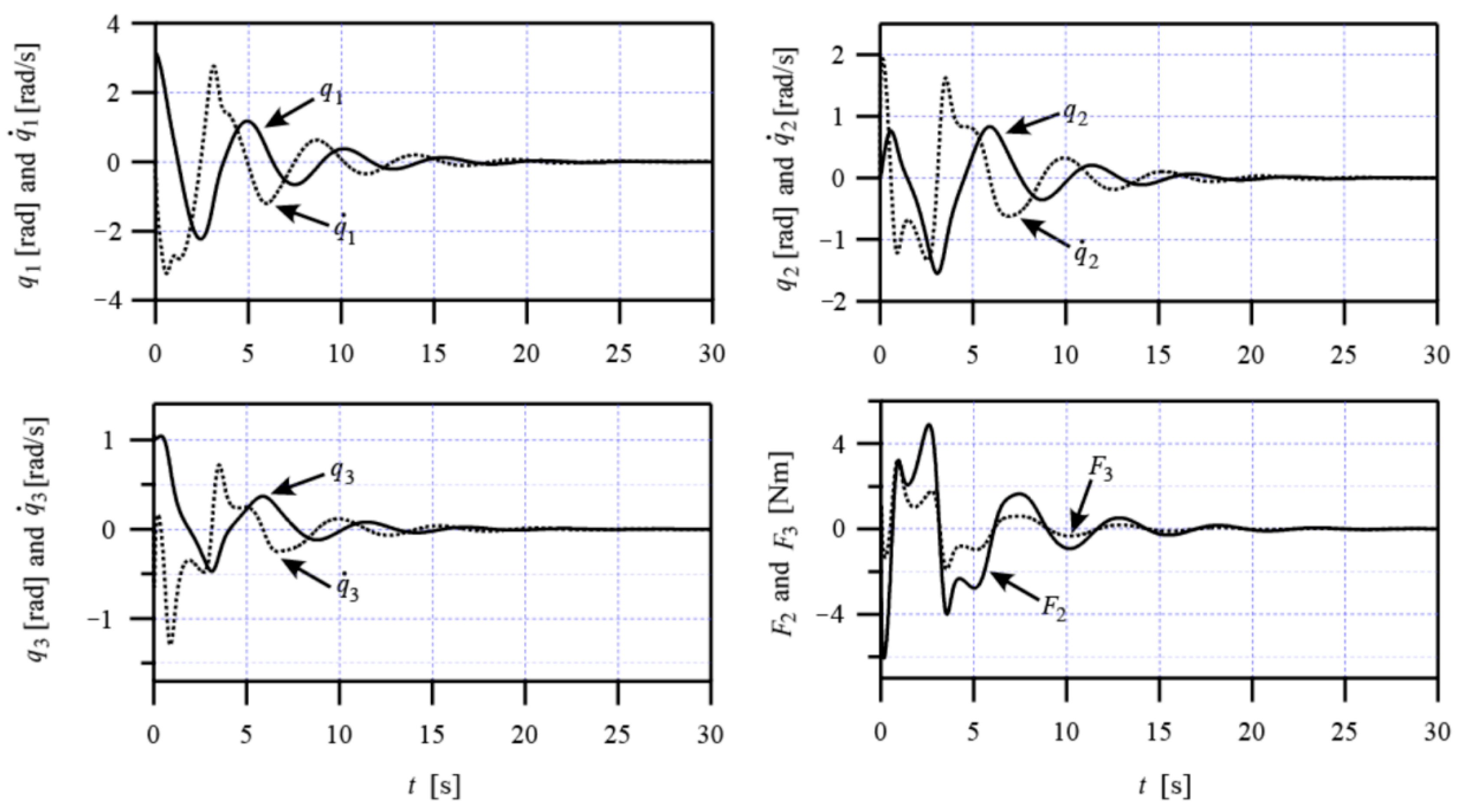
We chose the control parameters of the PsD controller in (2) to be r 1 = 3 , r 2 = 1 ,   r 3 = 3 , r 4 = 1 . The simulation results of the closed-loop control system (1) and (2) are shown in Figure 2. Note that the STHM system can be stabilized at the origin equilibrium point by the PsD controller. By this controller, the stabilization time of the control system is less than 20 s and the absolute value of input torque is less than 6 Nm. As shown in the Figure 3 of [22], the stabilization time is about 25 s and the maximum absolute input value of torque is 10 Nm. The comparison shows the advantages of the developed PsD controller in this paper.
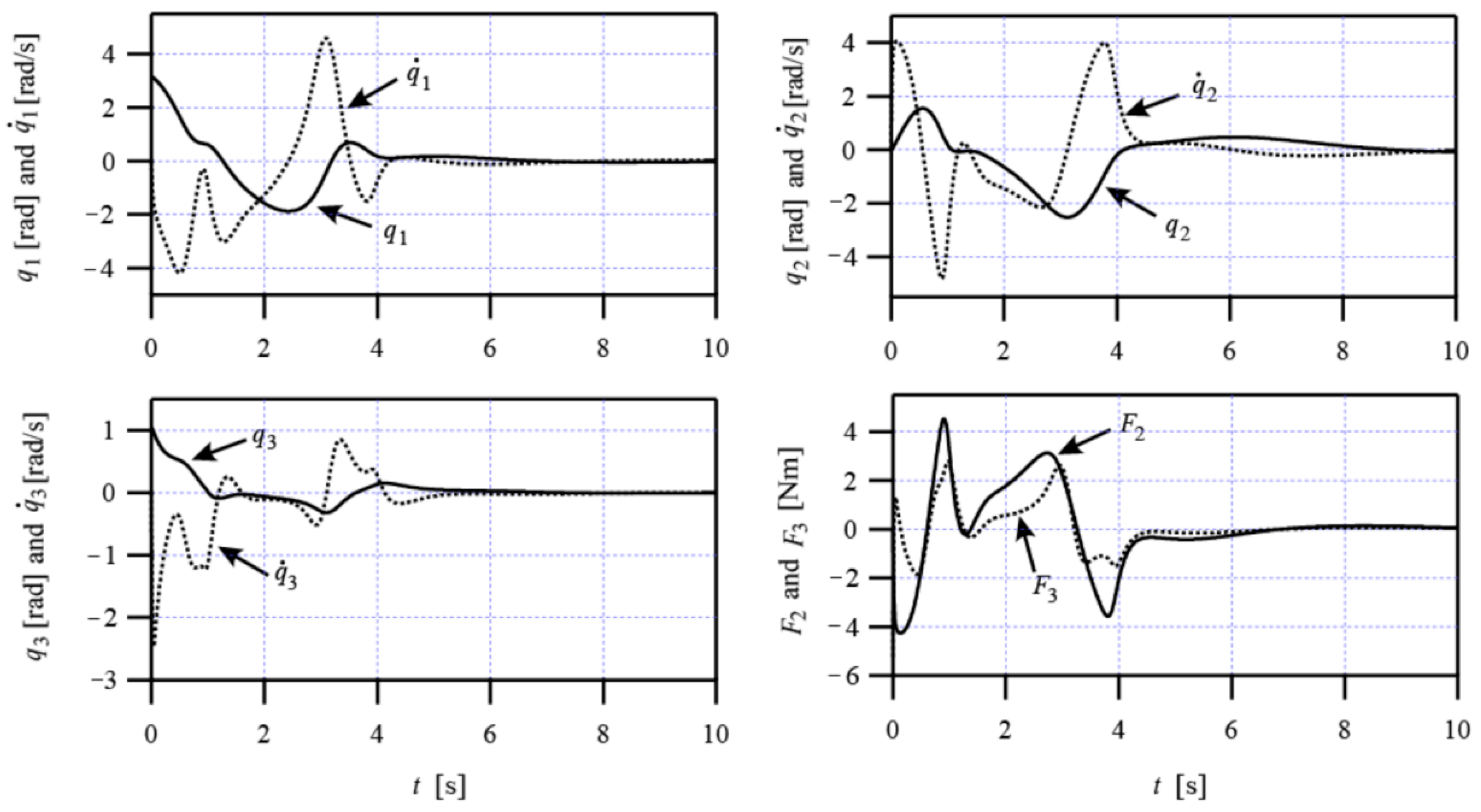
For the PD controller in (7), the control parameters were selected to be μ 1 = 1 , μ 2 = 0.5 ,   μ 3 = 2.5 , μ 4 = 5 . By this controller, the system (1) can also be stabilized at the origin point. The stabilization time of the closed-loop system (1) and (7) is about 10 s. Moreover, the absolute value of input torque is less than 4.5 Nm. These show that the control system’s performance by the PD controller is better than that by the PsD controller. In addition, we compare the simulation results in Figure 3 with the results in [21]. In the Figure 3 of [21], the stabilization time is about 12 s and the maximum absolute value of input torque is greater than 60 Nm. Moreover, the motion trajectory of the STHM system in [21] is not as smooth as that in Figure 3. Obviously, the performance of the control system in [21] is far from good as that in here. These show the superiority of our proposed PD controller.
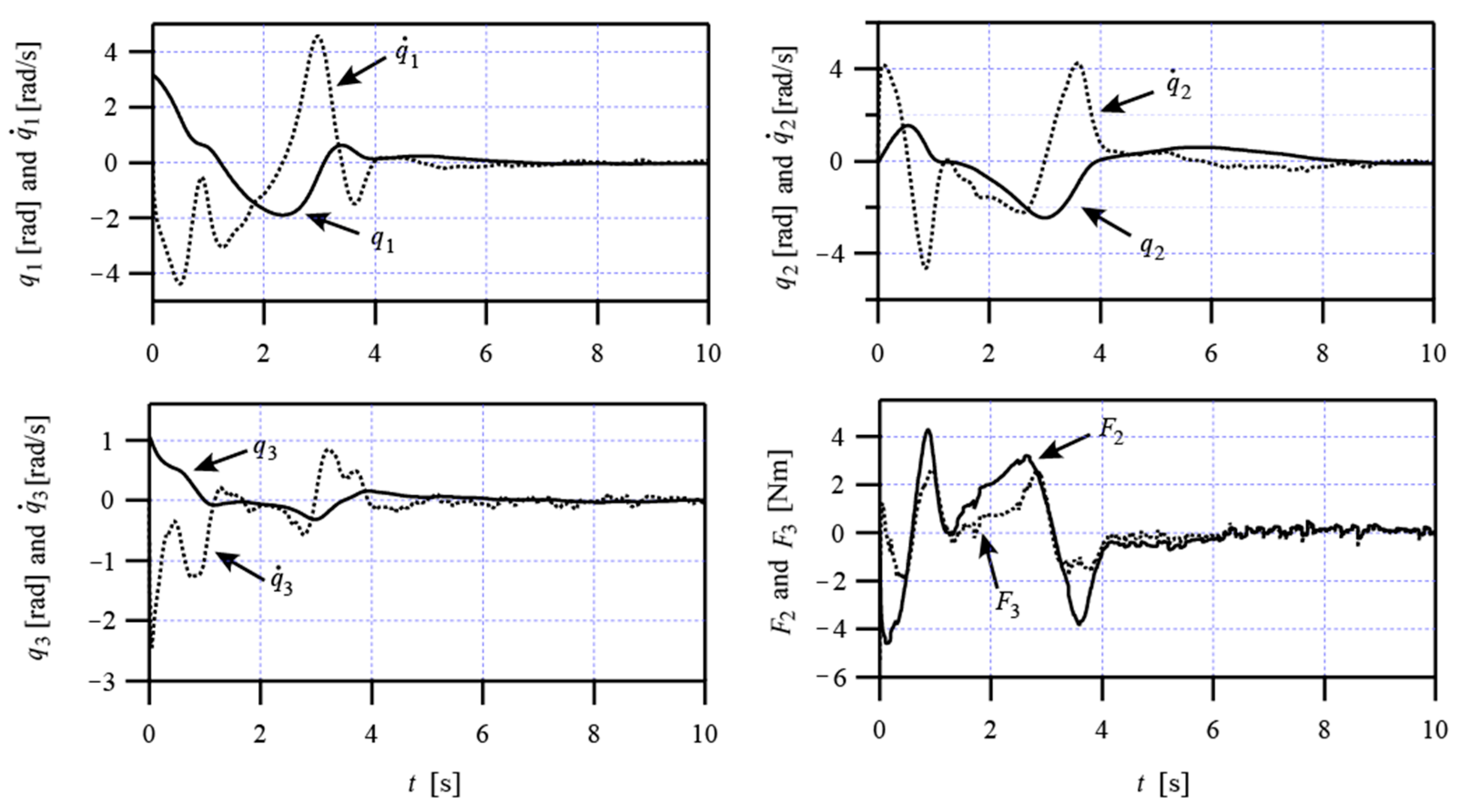
In order to verify the effectiveness of the PD controller in an actual environment, we carried simulation experiments with the white noise (peak value: ±0.15) in the measured q ˙ and with parameter uncertainties ( m i ( i = 1 , 2 , 3 ) is 10% smaller than its nominal value, J i ( i = 1 , 2 , 3 ) is 10% larger than their nominal values). In this case, the proposed PD controller is still effective (see Figure 4).

5. Conclusions

In this paper, the stabilization control problem for an underactuated spring-coupled three-link horizontal manipulator (STHM) was discussed. By analyzing the physical characteristics of this mechanical system, an energy-absorbing idea was used to design two types of virtual friction stabilizing controllers, i.e., PsD controller and PD controller. The PsD controller can stabilize the STHM at the origin from an initial position in the whole motion space except for three equilibrium points. In contrast, the PD controller can globally stabilize the STHM at the objective position. Simulation results demonstrate the validity and superiority of our developed control strategy. In the future, we will deeply study how to extend the energy-absorbing idea to the motion control of a spring-coupled n-link (n ≥ 4) horizontal manipulator. Moreover, the design of disturbance observer and robust stabilizing controller for the STHM will also be further discussed on the base of the research results in this paper.

Author Contributions

Methodology, A.Z. and S.G. software, L.F. and G.P.; writing—original draft preparation, Y.W.; writing—review and editing, A.Z. All authors have read and agreed to the published version of the manuscript.

Funding

This work was supported in part by the Natural Science Foundation Program of Shandong Province under Grant no. ZR2019YQ28, the Development Plan of Youth Innovation Team of University in Shandong Province under Grant no. 2019KJN007, and the National Natural Science Foundation of China under Grant Nos. 61773193, 62103177 and 61903171.

Institutional Review Board Statement

Not applicable.

Informed Consent Statement

Not applicable.

Data Availability Statement

The readers can access the data reported in this paper from the corresponding author.

Conflicts of Interest

The authors declare no conflict of interest.

References

  1. Liu, Y.; Yu, H. A survey of underactuated mechanical systems. IET Control Theory Appl. 2013, 7, 921–935. [Google Scholar] [CrossRef] [Green Version]
  2. Oriolo, G.; Nakamura, Y. Control of mechanical systems with second-order nonholonomic constraints: Underactuated manipulators. In Proceedings of the 30th IEEE Conference on Decision and Control, Brighton, UK, 11–13 December 1991; pp. 2398–2403. [Google Scholar]
  3. Rudra, S.; Barai, R.; Maitra, M. Nonlinear state feedback controller design for underactuated mechanical system: A modified block backstepping approach. ISA Trans. 2014, 53, 317–326. [Google Scholar] [CrossRef] [PubMed]
  4. Huang, J.; Ri, S.; Fukuda, T.; Wang, Y. A disturbance observer based sliding mode control for a class of underactuated robotic system with mismatched uncertainties. IEEE Trans. Autom. Contr. 2019, 64, 2480–2487. [Google Scholar] [CrossRef]
  5. Xin, X. Nonlinear Swing down Control of the Acrobot—ScienceDirect. IFAC—PapersOnLine 2020, 53, 5813–5818. [Google Scholar] [CrossRef]
  6. Gonzalez, P.; Werner, H. Wide range stabilization of a Pendubot using quasi-LPV predictive control. IFAC—PapersOnLine 2019, 52, 164–169. [Google Scholar]
  7. Zhang, A.; She, J.; Qiu, J.; Yang, C.; Alsaadi, F. Design of motion trajectory and tracking control for underactuated cart-pendulum system. Int. J. Robust Nonlinear Control 2019, 29, 2458–2470. [Google Scholar] [CrossRef]
  8. Wu, X.; Xu, K.; Ma, M.; Ke, L. Output feedback control for an underactuated benchmark system with bounded torques. Asian J. Control 2021, 23, 1466–1475. [Google Scholar] [CrossRef]
  9. Iriarte, R.; Aguilar, L.T.; Fridman, L. Second order sliding mode tracking controller for inertia wheel pendulum. J. Frankl. Inst. 2013, 350, 92–106. [Google Scholar] [CrossRef]
  10. Li, Z.; Dixon, R. Robust non-minimal state feedback control for a Furuta pendulum with parametric modelling errors. IEEE Trans. Ind. Electron. 2020, 68, 7341–7349. [Google Scholar]
  11. Spong, M. The swing up control problem for the acrobot. IEEE Control Syst. Mag. 1995, 15, 49–55. [Google Scholar]
  12. Lai, X.; She, J.; Yang, S.; Wu, M. Comprehensive unified control strategy for underactuated two-link manipulators. IEEE Trans. Syst. Man Cybern. B (Cybern.) 2009, 39, 389–398. [Google Scholar] [PubMed]
  13. Yu, T.; Zhao, W.; Yang, K. Sliding mode variable structure control for a class of underactuated systems. Control Eng. 2019, 26, 1824–1829. (In Chinese) [Google Scholar]
  14. Moreno-Valenzuela, J.; Aguilar-Avelar, C.; Puga-Guzmán, S.; Santibáñez, V. Adaptive neural network control for the trajectory tracking of the Furuta pendulum. IEEE Trans. Cybern. 2016, 46, 3439–3452. [Google Scholar] [CrossRef] [PubMed]
  15. Xu, K.; Timmermann, J.; Trachtler, A. Swing-up of the moving double pendulum on a cart with simulation based LQR-Trees. IFAC—PapersOnLine 2017, 50, 4094–4100. [Google Scholar] [CrossRef]
  16. Sun, N.; Fang, Y.; Zhang, X. Energy coupling output feedback control of 4-DOF underactuated cranes with saturated inputs. Automatica 2013, 49, 1318–1325. [Google Scholar] [CrossRef]
  17. Lai, X.; Zhang, A.; She, J.; Wu, M. Motion control of underactuated three-link gymnast robot based on combination of energy and posture. IET Control Theory Appl. 2011, 5, 1484–1493. [Google Scholar] [CrossRef]
  18. Xin, X.; She, J.-H.; Yamasaki, T.; Liu, Y. Swing-up control based on virtual composite links for n-link underactuated robot with passive first joint. Automatica 2009, 45, 1986–1994. [Google Scholar] [CrossRef]
  19. Wu, J.; She, J.; Wang, Y.; Su, C.-Y. Position and posture control of planar four-link underactuated manipulator based on neural network model. IEEE Trans. Ind. Electron. 2019, 67, 4721–4728. [Google Scholar] [CrossRef]
  20. Mullhaupt, P.; Srinivasan, B.; Bonvin, D. Analysis of exclusively kinetic two-link underactuated mechanical systems. Automatica 2002, 38, 1565–1573. [Google Scholar] [CrossRef] [Green Version]
  21. Zhang, A.; Lai, X.; Wu, M.; She, J. Global stabilization of underactuated spring-coupled three-link horizontal manipulator using position measurements only. Appl. Math. Model. 2015, 39, 1917–1928. [Google Scholar] [CrossRef]
  22. Zhang, A.; Lai, X.; Wu, M.; She, J. Nonlinear stabilizing control for a class of underactuated mechanical systems with multi degree of freedoms. Nonlinear Dyn. 2017, 89, 2241–2253. [Google Scholar] [CrossRef]
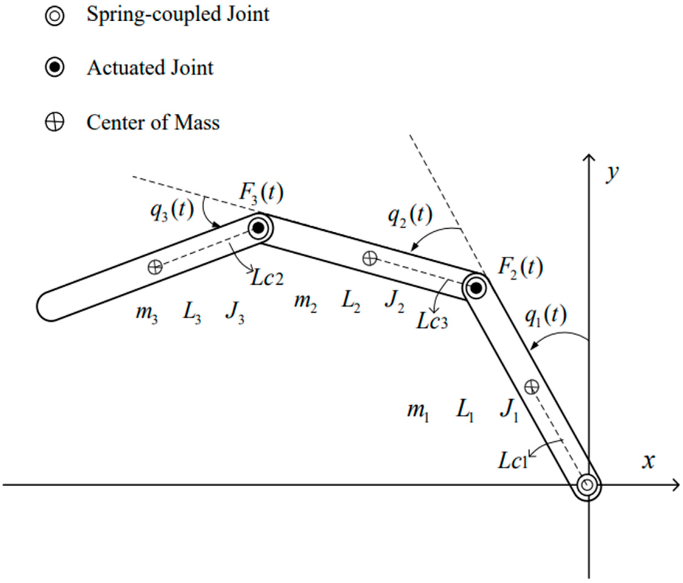
Figure 1. Spring-coupled three-link horizontal manipulator (STHM).
Mathematics 10 01832 g001
Figure 2. Simulation results for the control system (1) and (2).
Mathematics 10 01832 g002
Figure 3. Simulation results for the control system (1) and (7).
Mathematics 10 01832 g003
Figure 4. Simulation results for the control system (1) and (7) with parameter perturbation and external disturbances.
Mathematics 10 01832 g004
Publisher’s Note: MDPI stays neutral with regard to jurisdictional claims in published maps and institutional affiliations.