Article

Study on Failure Characteristics and Control Technology of Roadway Surrounding Rock under Repeated Mining in Close-Distance Coal Seam

1
College of Mining, Guizhou University, Guiyang 550025, China
2
State Key Laboratory of Public Big Data, Guizhou University, Guiyang 550025, China
3
Faculty of Land and Resources Engineering, Kunming University of Science and Technology, Kunming 650093, China
4
School of Engineering, University of Warwick, Coventry CV4 7AL, UK
*
Authors to whom correspondence should be addressed.
Mathematics 2022, 10(13), 2166; https://doi.org/10.3390/math10132166
Submission received: 19 May 2022 / Revised: 14 June 2022 / Accepted: 20 June 2022 / Published: 21 June 2022

Abstract

:
In this study, taking the Sheng’an coal mine as an engineering background, the failure characteristics of the surrounding rock of a roadway under repeated mining in a close-distance coal seam is comprehensively illustrated through field measurements (e.g., drilling imaging), theory analysis and numerical simulation (finite difference method (FDM)). The results show that although the return airway 10905 remains intact, the apparent failure of the roadway’s roof and the coal pillar can be observed. In addition, the expression of floor failure depth caused by upper coal seam mining is obtained through elastic-plastic theory. Meanwhile, the deformation of the surrounding rock of the roadway increases with the increase of repeated mining times, especially for the horizontal displacement of the roadway on the coal pillar side. Moreover, the cracks’ evolution of surrounding rock in the roadway can be observed as asymmetric characteristics. Finally, the stability control technology of “asymmetric anchor net cable + I-steel” is proposed to prevent potential mining disasters, and the feasibility of this support scheme is verified by numerical simulation and field practices. It can meet the requirement of safe mining and provide guidelines to effectively solve the failure of a roadway in close-distance coal seam mining.

1. Introduction

In the process of coal formation, it will experience many crustal movements, and the coal measure strata are hosted in sedimentary rocks. Therefore, multiple coal seams will appear in the same coal measure strata with a small distance between the adjacent multi-coal seams. Different from the mining of a single coal seam, the mining activities of a close coal seam group can be influenced by each other’s coal seams with the characteristics of mutual disturbance, stress concentration and severe damage to the mining roadway [1,2,3,4]. The roadway in the lower coal seam is significantly affected by the caving gangue generated after upper coal seam mining and the dynamic pressure due to the mining activities of the adjacent working face. Therefore, the roof management of the working face under repeated mining should be paid more attention in order to prevent the occurrence of mining disasters. In the process of coal formation, it will experience many crustal movements, and the coal measure strata are hosted in sedimentary rocks. Therefore, multiple coal seams will appear in the same coal measure strata with a small distance between the adjacent multi-coal seams. Different from the mining of a single coal seam, the mining activities of a close coal seam group can be influenced by each other’s coal seams with the characteristics of mutual disturbance, stress concentration and severe damage to the mining roadway [5,6,7,8,9,10]. The roadway in the lower coal seam is significantly affected by the caving gangue generated after upper coal seam mining and the dynamic pressure due to the mining activities of the adjacent working face.
Currently, the support theory and control technology of the surrounding rock of a roadway under repeated mining in a close-distance coal seam is comprehensively illustrated. Refs.studied the dynamic stress evolution law of floor in the process of repeated mining and discussed the distribution characteristics of surrounding rock stress and the displacement of floor roadway. Meanwhile, the grouting bolt to strengthen shallow broken surrounding rock and hollow grouting anchor cable to strengthen deep cracks combined with double anchor mesh shotcrete support were proposed to fully mobilize the self-supporting ability of the surrounding rock. In addition, Xiong et al. [11] illustrated the stress distribution of the floor under the repeated mining and the staggered arrangement of the roadway in the lower coal seam. Zhang et al. [12] illustrated that the lower coal mining roadway was prone to instability under the action of the low support strength of the roadway, the over-speed mining and the vertical arrangement of the upper coal seam roadway. Liu et al. [13] proposed the segmented support design technology to control different types of roofs, which can significantly improve the stress state of the surrounding rock. Using numerical simulation, Han et al. [14] conducted the roadway stability under a reinforcement support scheme. The results showed that the instability mechanism of the roadway met the requirements of an extremely close coal seam, and the section shrinkage rate remained at 5.29%. Cheng et al. [15] proposed three schemes of lengthening an anchor bolt combined support to solve the problem of significant roof subsidence in the roadway of the lower coal seam. Geng et al. [16] analyzed the plastic failure characteristics, stress distribution and displacement variation of the roadway under the influence of the superimposed stress after the upper coal seam mining. Then the comprehensive roof control technology of ‘broken roof hole + pressure relief hole + high pre-stressed anchor cable + single hydraulic prop’ was proposed.
Throughout the literature review, the current research mainly focused on the stress distribution law of a floor under a coal pillar in the close-distance coal seam group mining and the layout offset of a roadway in the lower coal seam. However, there are few studies proposing the stability control technology to support the surrounding rock of a roadway in the lower coal seam while considering the action of the caving gangue generated in the upper coal seam and the dynamic pressure due to the mining activities of the adjacent working face. There may be no residual coal pillar after the upper coal seam mining when the close-distance coal seam group adopts the downward mining method. In addition, the stress and displacement of the surrounding rock of the roadway under the repeated mining in the close-distance coal seam group should be explored in detail. Therefore, taking the Sheng’an coal mine in Guizhou Province (China) as an engineering background, this study aims to illustrate the failure characteristics and instability law of the surrounding rock of the roadway in the lower coal seam and the damage depth of the floor caused by the upper coal seam mining [17,18]. Most importantly, the corresponding support techniques are proposed and applied in engineering practices, which provide the guideline to control the stability of the surrounding rock of the roadway in similar mining conditions.

2. Engineering Background

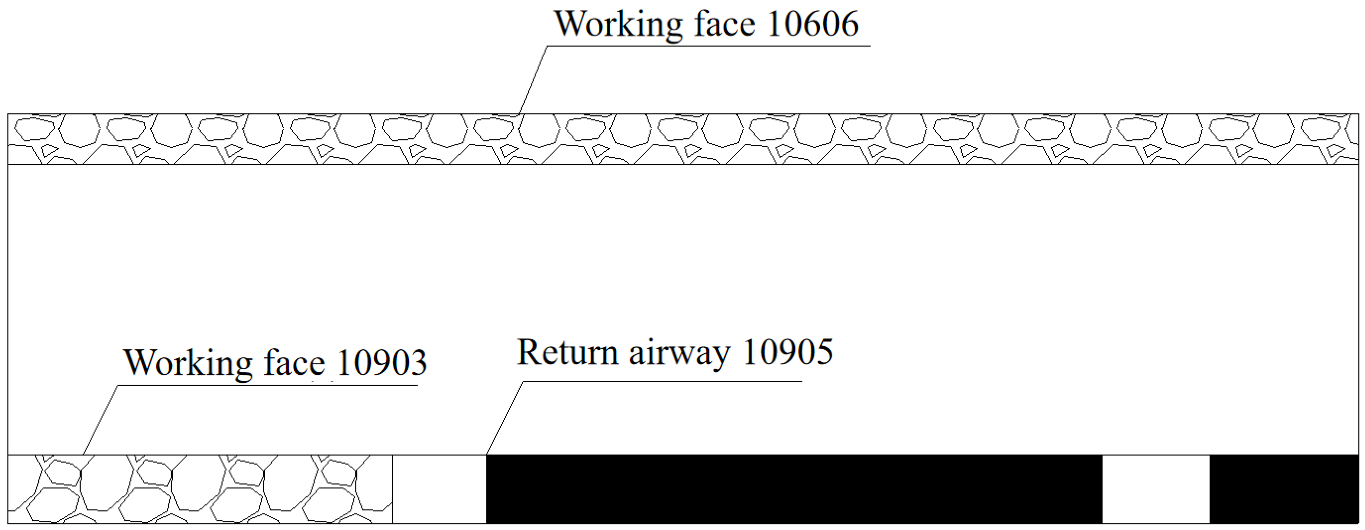
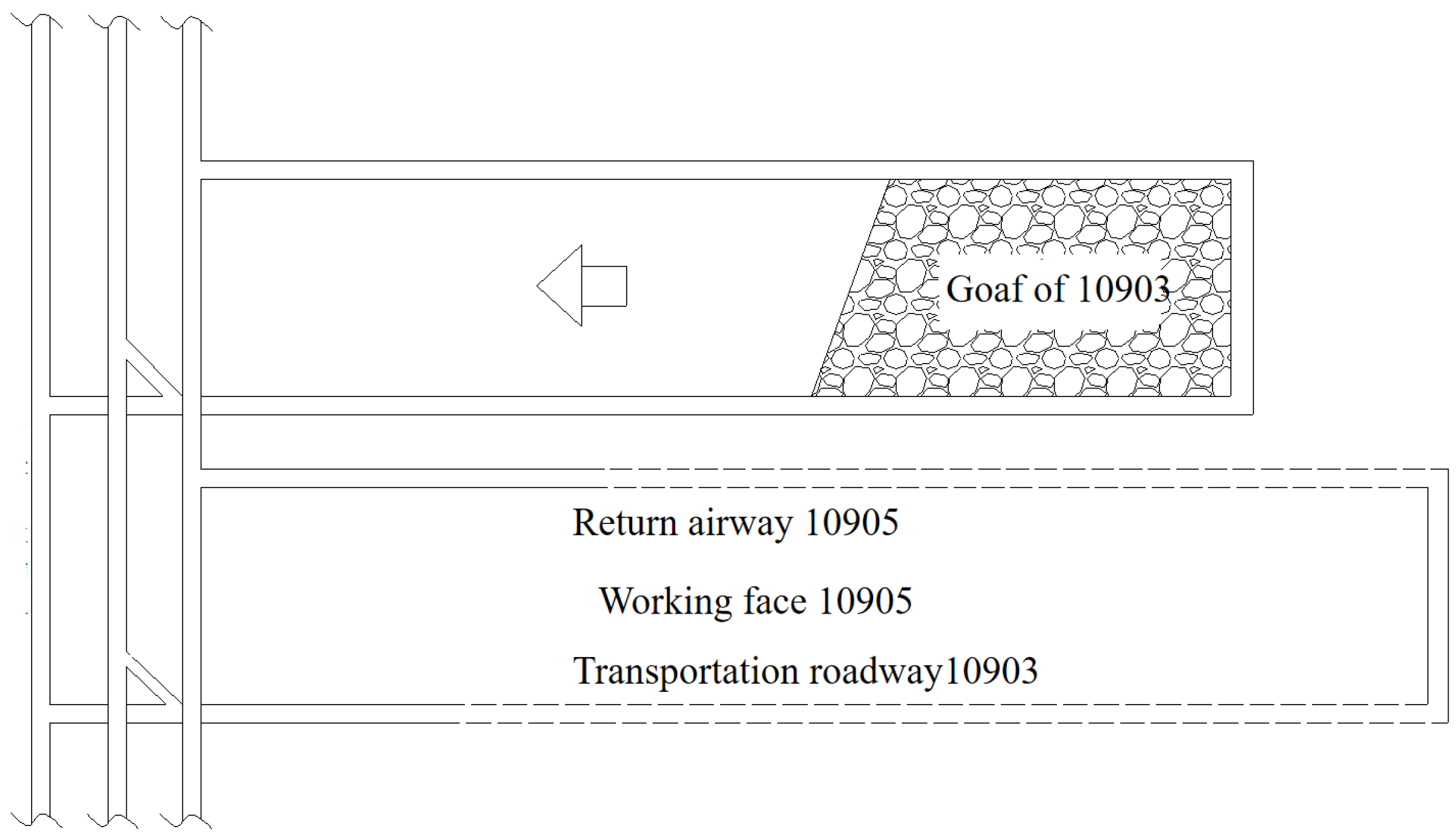
2.1. Geological Conditions

The Sheng’an coal mine has two main coal seams, named ##6 and ##9, respectively. The coal seam #9 is buried with a depth of 191 m and an average thickness of 1.81 m. Moreover, its roof is silty mudstone, argillaceous siltstone and mudstone, and its floor is mudstone, silty mudstone and argillaceous siltstone. On the other hand, the coal seam #6 with an average thickness of 1.26 m is away from coal seam #9 by 4.14–7.01 m, which is a typical close-distance coal seam group.
The working face 10905 is arranged in coal seam #9 without leaving the coal pillar, located in the south of working face 10903, as shown in Figure 1 and Figure 2. Moreover, the return airway of working face 10905 and the transportation roadway of working face 10903 are separated by coal pillars of 13 m. Therefore, significant roof subsidence and horizontal displacement of the return airway in working face 10905 during the excavation process can be observed due to the influence of upper coal seam #6 mining and the adjacent working face 10903 mining. Notably, various disasters (e.g., roof leakage and roof caving) can be observed, which greatly affect the safe and efficient production of the mine in working face 10905.

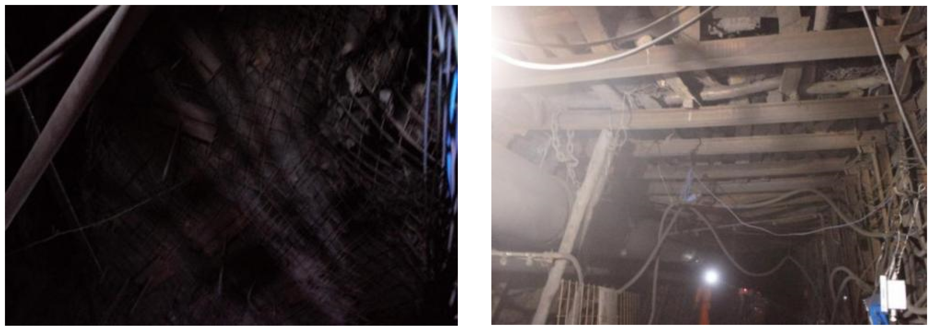
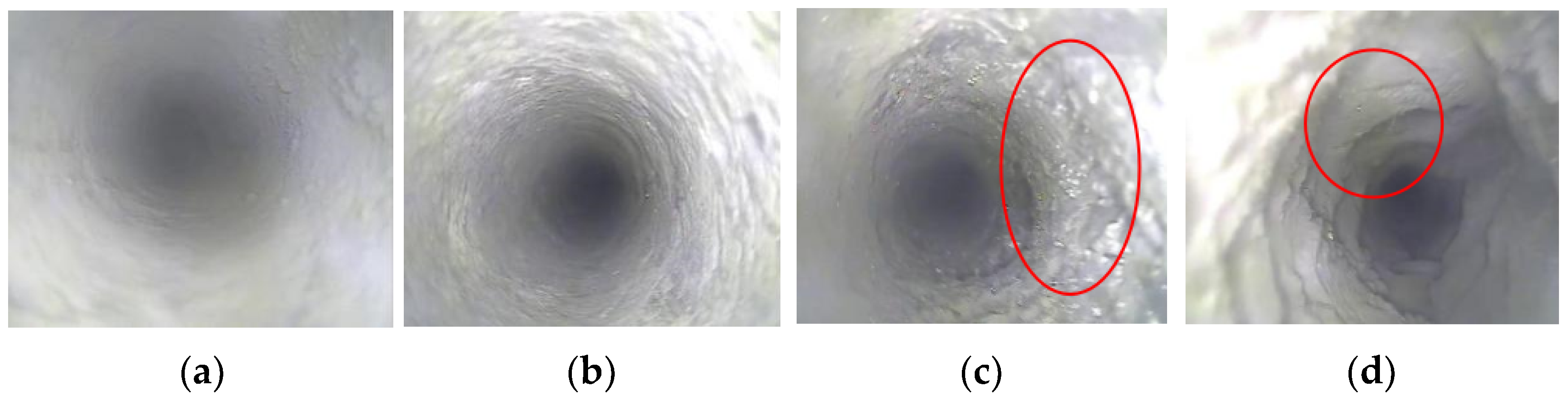
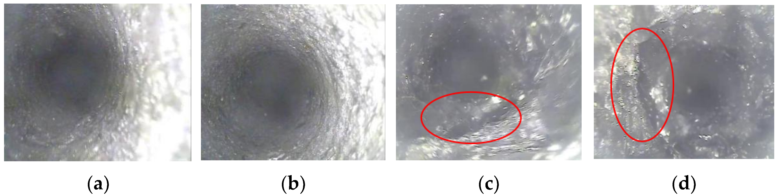
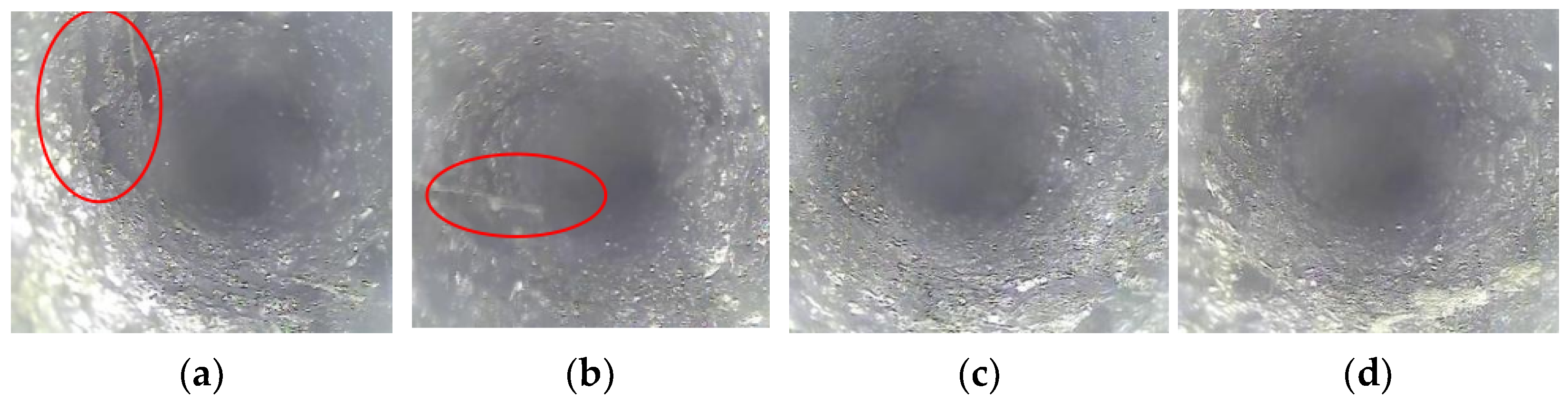
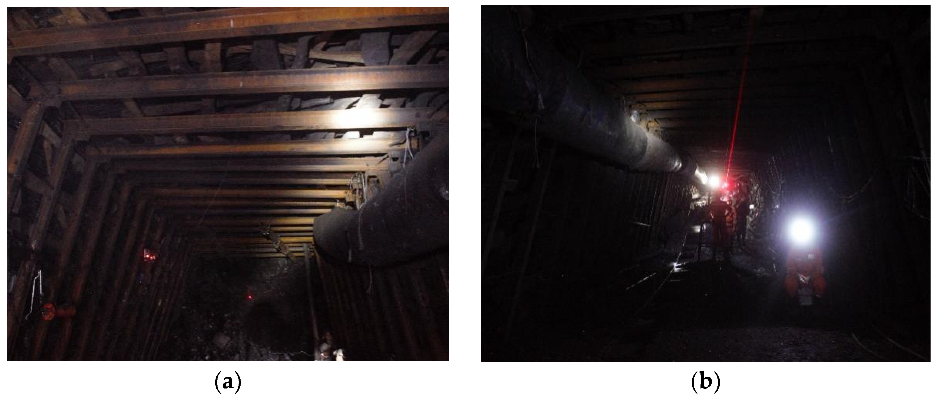
2.2. Roof Failure Characteristics of Return Airway in Working Face 10905

The working face 10905 mined coal seam #9 is arranged below the 10606 working face of coal seam #6. Originally, the bolt + I-steel combined symmetric support scheme was adopted as shown in Figure 3. The row spacing between the bolts is 0.8 × 0.8 m, and the spacing between the sheds and frames is 0.8 m. However, the sidewall of the return airway is not fully supported, and the I-steel is only used to maintain the stability of the roadway. Due to the neglect of the asymmetry of the stress and deformation of the roadway sidewall, severe sidewall heave and roof subsidence deformation can still be observed in the process of roadway excavation, as shown in Figure 4.
Based on the results of drilling images, Figure 5 illustrates that there are few cracks in the upper part of the roadway roof from 2.5 to 3.0 m, while the surrounding rock of the borehole is relatively complete. In addition, an obvious transverse fracture in the upper roof 3.5 m can be observed, which is similar to the annular interval fracture zone. Moreover, the loose fracture of the surrounding rock in the borehole is observed at the upper roof of 4 m, and zoning fracture exists in shallow and deep parts of the roadway roof. On the other hand, the integrity of the surrounding rock in the borehole is good when the borehole depth on the coal pillar side of the roadway reaches 1.5–2 m as shown in Figure 6. When the drilling depth reaches 2.5 m, the coal body begins in a broken state. Meanwhile, the number of cracks is small, and there are few longitudinal cracks when the depth of the borehole on the side of the roadway increases to 1.5 m, as shown in Figure 7. With the increase of drilling depth, the shape of longitudinal fractures decreases, and the integrity of the surrounding rock is good at the drilling depth of 2.5–3 m. The comprehensive analysis shows that the roadway roof of working face 10905 is not fully broken, while the overall bearing capacity is weak. However, the roof and coal pillar side of the roadway are obviously broken in different areas. It is possible that a large deformation in the future working face mining may appear.

2.3. Instability Factors of Roadway

After coal seam #6 was mined, the floor strata were damaged to influence the mining of lower coal seam #9. Moreover, the coal seam #6 above the working face 10905 was mined without leaving the coal pillar. In addition, the rock strata activity of adjacent working face 10903 has not reached a stable state. The surrounding rock of the roadway in working face 10905 is again experiencing severe deformation and failure, especially in the coal pillar side of the roadway. Most importantly, the support method of the return airway in working face 10905 is unreasonable. Therefore, the roof subsidence of the roadway in working face 10905 is significant, and two sides of the roadway are seriously moved during the excavation process.

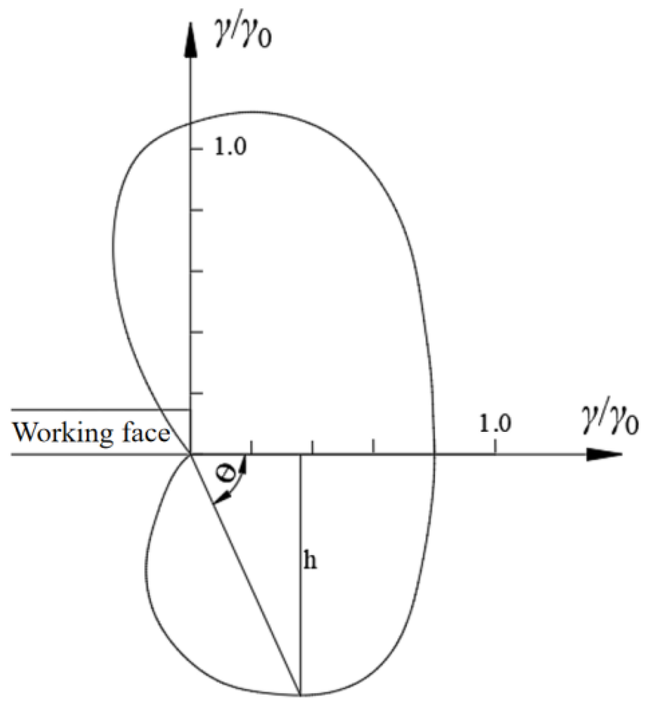
3. Calculation of Floor Damage Depth after Coal Seam #6 Mining

A rectangular goaf is generally formed in the rear after the working face is mined, and the ratio of the height of the mined coal seam to the width of the working face is minimal [19,20,21,22]. Therefore, the mechanical model of the longwall working face can be simplified, as shown in Figure 8.
According to the elastic-plastic theory and using the coordinate system as shown in Figure 9, the vertical stress and shear stress of the surrounding rock can be expressed as follows.
{ σ x = γ H L 2 r cos θ 2 ( 1 sin θ 2 sin 3 θ 2 ) ( 1 x ) γ H σ y = γ H L 2 r cos θ 2 ( 1 + sin θ 2 sin 3 θ 2 ) τ x y = γ H L 2 r cos θ 2 sin θ 2 cos 3 θ 2
where L and H are the length and buried depth of the working face, γ is the bulk density of rock mass, x is lateral stress ratio, r is the limit failure distance ahead of the working face, θ is the angle between the edge line and the horizontal direction at the maximum yield depth h.
According to the actual mining situation of the Sheng’an coal mine, the lateral pressure coefficient is 1, and then the principal stress expression of the stope edge can be deduced as follows.
{ σ 1 = γ H 2 L r cos θ 2 ( 1 + sin θ 2 ) σ 2 = γ H 2 L r cos θ 2 ( 1 sin θ 2 ) σ 3 = μ γ H L r cos θ 2
where μ is the Poisson’ s ratio of surrounding rock.
Assuming that the failure of surrounding rock obeys the Mohr-Coufomb criterion, the following expression can be obtained.
σ 1 ξ σ 3 = R c
ξ = 1 + sin ϕ 1 sin ϕ
where Rc is the uniaxial compressive strength of surrounding rock, and φ is the internal friction angle of the surrounding rock.
Therefore, the yield failure depth (h) of floor rock caused by stress concentration in coal seam mining can be obtained as follows.
h = γ 2 H 2 L 4 R c 2 cos 2 θ 2 ( 1 + sin θ 2 ) 2 sin θ
The maximum failure depth of floor strata under the plane stress state is expressed as follows.
h max = 1.57 γ 2 H 2 L 4 R c 2
It can be observed that the damage depth of floor rock increases linearly with the square of inclined length and the buried depth of the working face, and decreases linearly with the square of the compressive strength of floor rock.
On the other hand, the failure zone near the stope edge (r′) can be expressed as follows.
r = γ 2 H 2 L 4 R c 2 cos 2 θ 2 ( 1 + sin θ 2 2 ε μ ) 2
where ε is the strain of the rock element in the plane strain state.
Therefore, the horizontal failure range of stope edge r0 at θ = 0° is shown as follows.
r 0 = γ 2 H 2 L ( 1 2 ε μ ) 2 4 R c 2
The failure depth of floor strata in lower coal seam (h′) can be calculated according to the geometric relationship under the plane strain state as follows.
h = r sin θ = γ 2 H 2 L 4 R 2 cos 2 θ 2 ( 1 + sin θ 2 2 ξ μ ) 2 sin θ
According to the comparison of the failure depth of floor strata under the plane stress and strain states, it can be seen that the failure range obtained under the plane stress state is larger than that under the plane strain state. Therefore, when the elastic-plastic theory is used to calculate the failure depth of floor strata, the calculation results in plane stress state are used to measure the failure depth of floor strata in coal mining. The influence of the joint fissures of the floor strata on the failure depth is then comprehensively considered, and Equation (6) is transformed as follows.
h max = 1.57 γ 2 H 2 L / ( 4 R c 2 δ 2 )
where δ is the influence coefficient of joint fissure in floor strata.
The average mining height and buried depth of coal seam #6 in Sheng’an Coal Mine is 1.35 m and 185 m, respectively. The length of the working face 10606 is 150 m. According to the experimental test results, the internal friction angle of cohesion of coal body #6 are 25.2° and 1.18 MPa, respectively. In addition, the friction coefficient of the contact surface between coal seam 5# and the floor is 0.32, and the influence coefficient of the joint fracture is 0.39. Moreover, the uniaxial compressive strength of floor strata is 14.9 MPa, and the bulk density of floor strata is 2300 kN/m3. The maximum stress concentration coefficient is 3.5. Inserting these geological parameters into Equation (10), the failure depth of floor strata caused by the upper coal seam #6 is 4.63 m, as follows.
h max = 1.57 γ 2 H 2 L / ( 4 R 2 δ 2 ) = 1.57 × 23 2 × 185 2 × 150 0.6084 × 31,900 2 4.63   m

4. Numerical Simulation of Roadway Instability under Repeated Mining

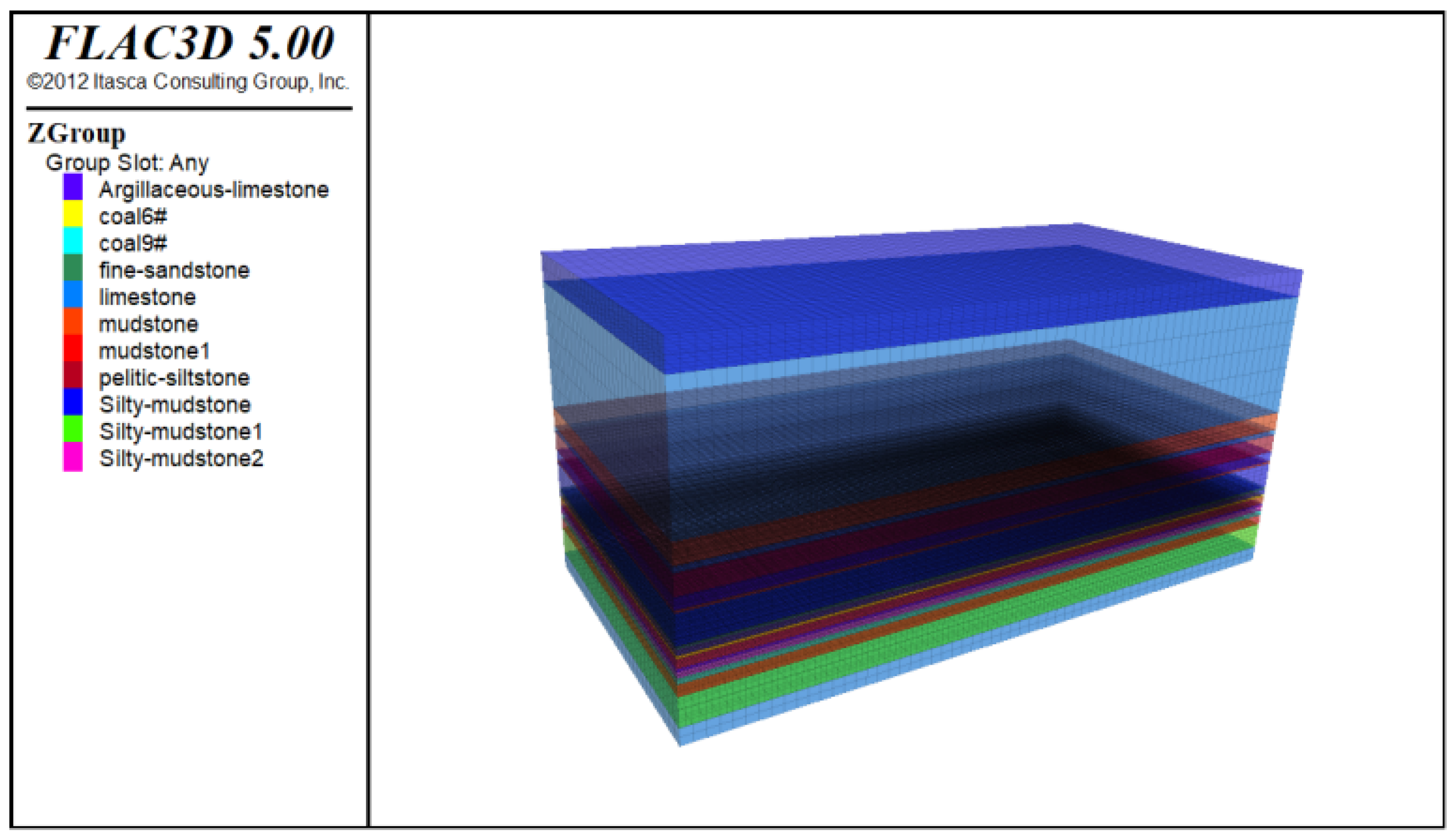
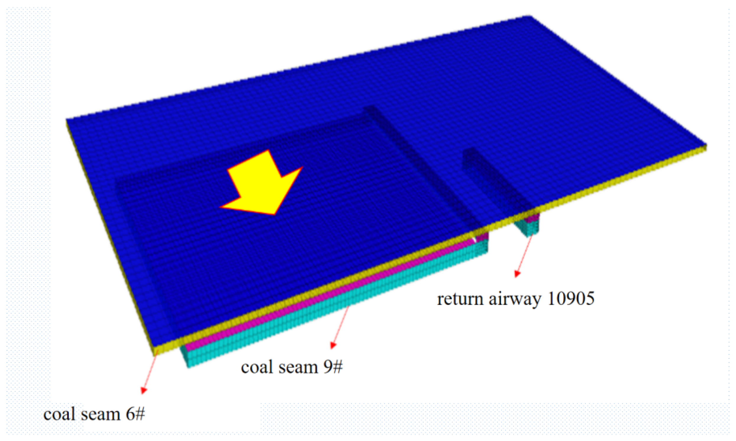
4.1. Numerical Model Establishment and Parameter Determination

In order to explore the influence of repeated mining on the instability law of the roadway, FLAC3D is used to illustrate the stress distribution law and the development of the plastic zone in the stope when the upper and lower coal seams are mined [23,24,25]. The numerical calculation model adopts the Mohr-Coulomb constitutive model because it is a nonlinear model and is widely used in the calculation of the actual bearing capacity and failure load of rock mass in underground space engineering. FLAC 3D can simulate the mechanical properties and plastic flow analysis of three-dimensional structures of soil, rock and other materials by adjusting the polyhedral units. Based on the finite difference method, the computational region is divided into several tetrahedral elements, each of which follows the Moor-Coulomb constitutive model under given boundary conditions.
According to the occurrence conditions of the coal seam in the Sheng’an coal mine, the numerical simulation model is established with the length, width and height of 250 m, 120 m and 108 m, respectively, as shown in Figure 10. The bottom boundary of the model is fixed, and the displacement in the X, Y and Z directions of the bottom boundary is set as zero. In addition, the top of the model is a free boundary. The upper rock layer is applied to the equivalent load, and the self-balancing treatment is carried out before the excavation of the model.
The average buried depth of coal seam #6 is about 185 m, and the uniform load is applied according to the buried depth. The average density of rock strata is 2500 kg/m3, and the lateral stress coefficient is 1. In addition, according to the experimental tests of rock specimens collected from the Sheng’an coal mine and then conducted in the laboratory of Guizhou University, various physical and mechanical parameters (e.g., volumetric weight, compressive strength, tensile strength, Poisson’s ratio, cohesion and internal friction angle) of coal seam and rock mass are obtained and used in the numerical model as listed in Table 1.

4.2. Stress and Displacement Characteristics of Surrounding Rock in Lower Coal Seam

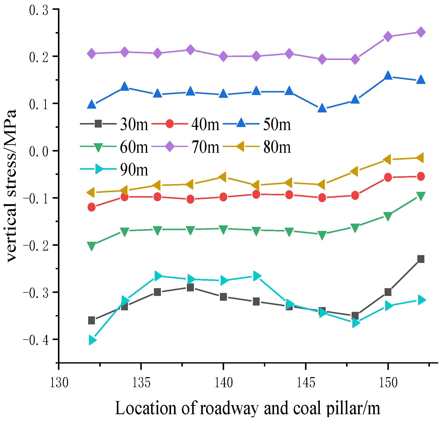
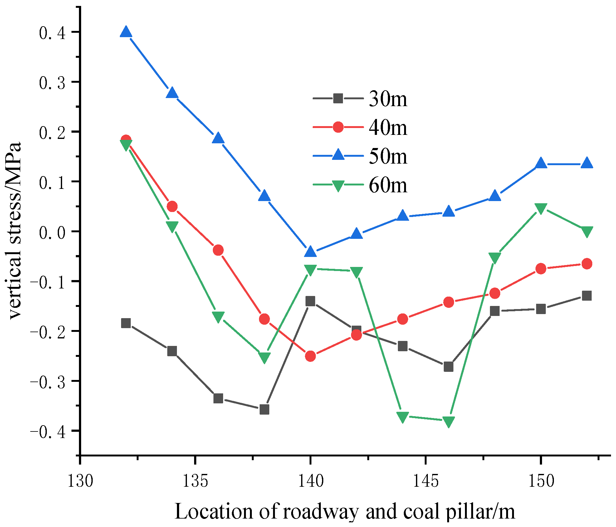
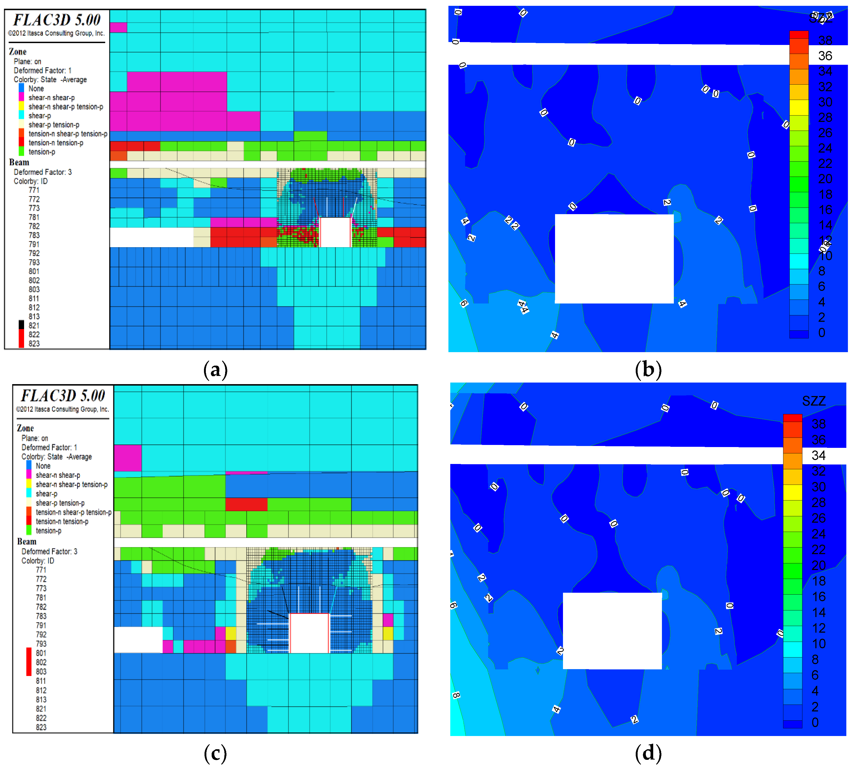
4.2.1. Stress Evolution Law

Figure 11 illustrates the stress distribution of surrounding rock in lower coal seam mining #9 with the working face advancing of 20 m, 40 m, 60 m and 80 m. Specifically, the stress concentration coefficient at the coal wall of the working face on the open-off cut is significantly reduced with the working face advancing of 20 m under the pressure relief effect of coal seam #6 mining. With the working face advancing increasing to 40 m, the small stress value of the roof and floor of coal seam #9 has been extended to an extensive range, and a small range of the stress concentration area appears in front of the coal wall of the working face. Subsequently, part of the pressure relief is reduced to connect into slices, and the force is redistributed again when the advance of the working face is 60 m. With the continuous increase of working face advancing, the pressure relief range of the connected slices increases periodically, while the increased effect of the pressure relief range is not apparent in the upper and lower ranges. It indicates that the rock entirely collapses, the rear of the working face is compacted, and the pressure relief range reaches stability.

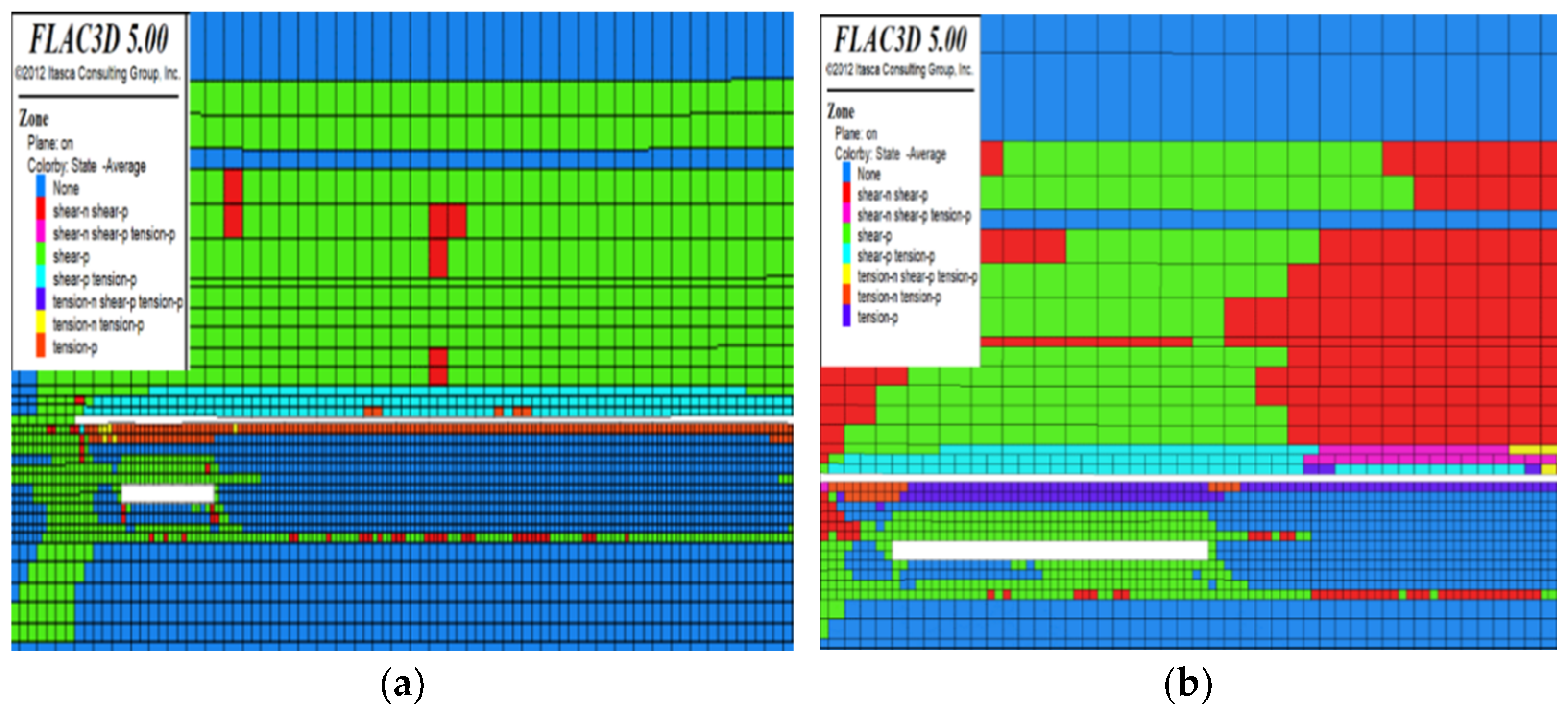
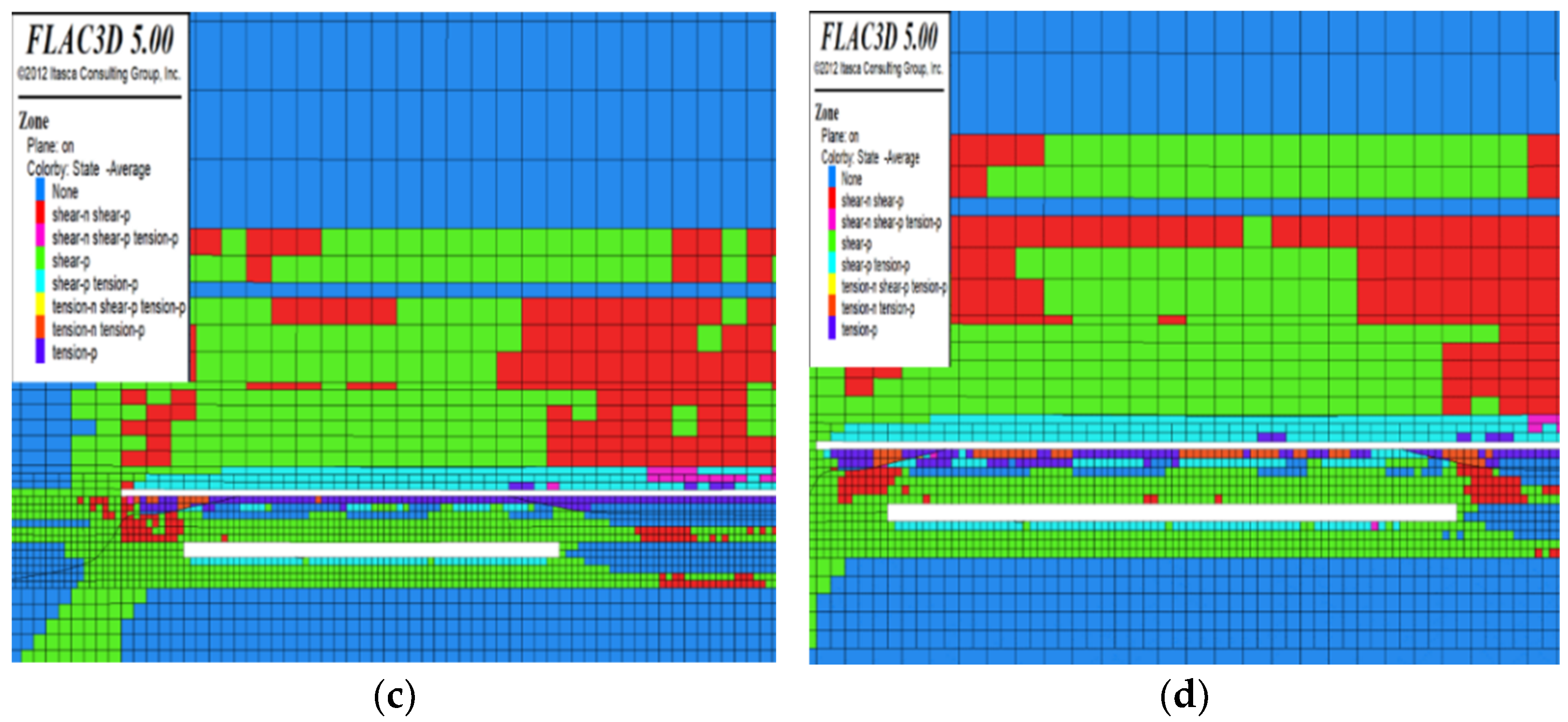
4.2.2. Evolution Law of Plastic Zone

Figure 12 illustrates the distribution of plastic zone during the lower coal seam mining. It can be seen that there is a large range of plastic area at the cutting hole, while the plastic range at the coal wall is less under the working face advancing 20 m. Subsequently, the plastic range in the front of the working face and floor strata increase with the advance of working face increasing to 40 m, and the roof of the goaf is still in the elastic area. Moreover, the plastic zones of overlying and floor strata increase significantly at the working face advancing 60 and 80 m.

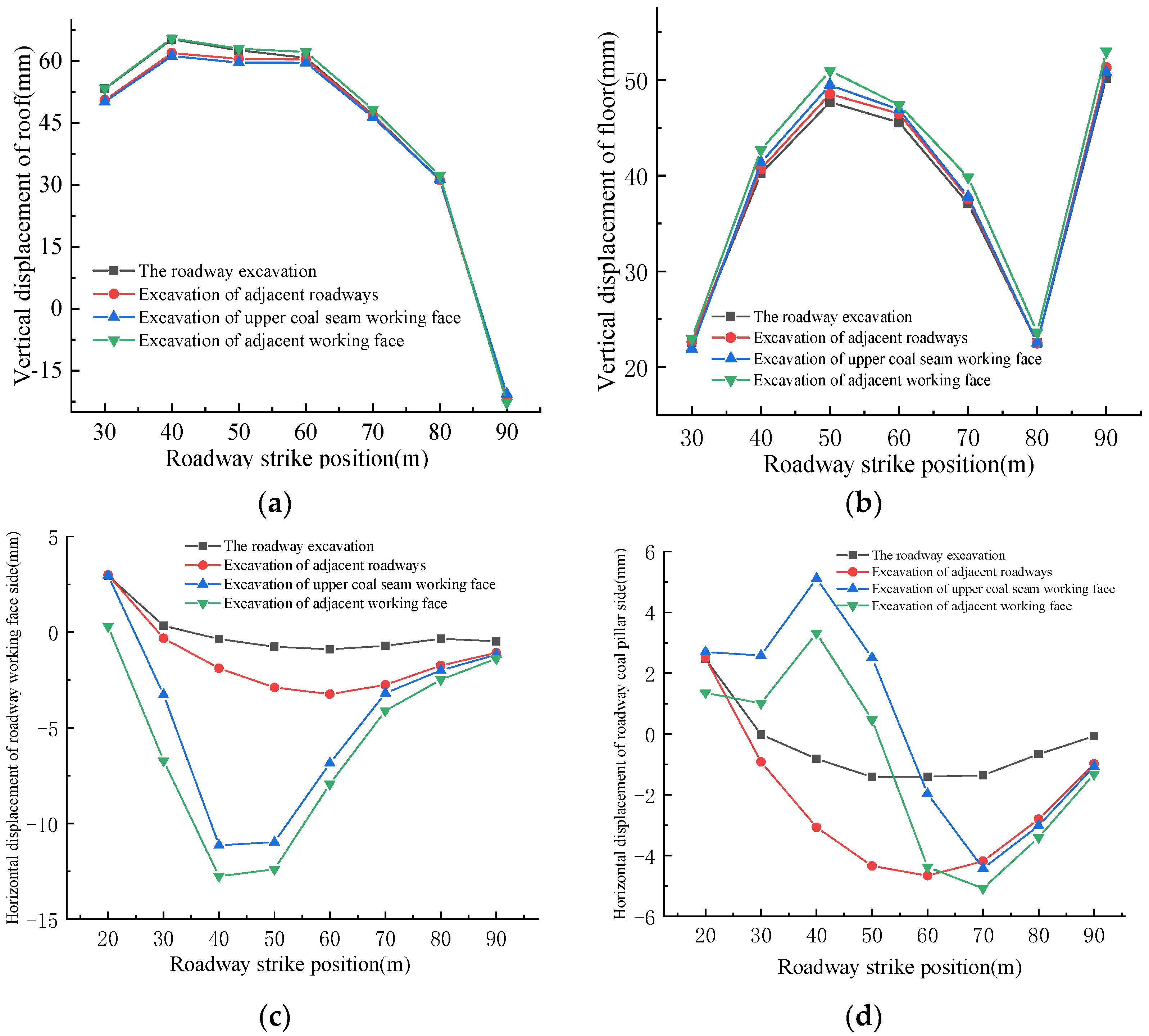
4.3. Stress and Deformation Evolution Law of Surrounding Rock under Repeated Mining

Figure 13 illustrates the model excavation scheme to fully mine the upper coal seam and excavate the adjacent roadway of 30 m. Moreover, the gob-side entry retaining technology without the coal pillar is used in the mining of upper coal seam #6.
Figure 14 shows the vertical stress distribution at the position of the reserved roadway and the roof of the coal pillar in the upper coal seam mining. The pressure relief effect at the position of reserved roadway and coal pillar is good with the low stress value due to the small space between the two coal seams. Moreover, the stress value at the position of reserved roadway strike 30 m and 90 m is slightly higher with the average value of about 0.3 MPa due to the influence of the coal pillar boundary in the goaf, and the direction of vertical stress is downward. On the other hand, the direction of vertical stress at the position of the reserved roadway strike 40 m, 50 m, 70 m and 80 m is upward because the lower strata of the goaf is changed from original extrusion pressure into tensile stress and the cracks also begin to be expended after the upper coal seam mining. Meanwhile, the location of a roadway strike at 60 m may be the first weighing site, and the overlying strata is collapsed and compacted resulting in the downward direction of vertical stress.
Figure 15 illustrates that there exists a certain of lateral pressure concentration because of the adjacent roadway excavation to cause the vertical stress of the reserved roadway and the roof of the coal pillar increasing firstly and then decreasing from near to far. Figure 16 illustrates that the vertical stress distribution at the position of 40 m and 50 m along the roadway has limited change, while the vertical stress distribution is greatly changeable at the position of 30 m and 60 m along the roadway behind the working face. Meanwhile, the stress in the roof of the roadway is large. In summary, the excavation of the upper coal seam has a significant effect on the stress value and distribution of the reserved roadway and coal pillar because of the low rock strength and the small interlay space of two coal seams, while the stress value and range is limited changed under the influence of the excavation of adjacent roadway and local roadway.
Figure 17 illustrates the variation of horizontal displacement of the roadway along with the strike position. Under the repeated mining, the deformation of surrounding rock in the roadway increases with the increase of mining times, especially for the coal pillar side. The deformation variables of the two sides are prone to have asymmetric situations during the mining process, and the stability maintenance of the coal pillar side needs to be emphasized.

5. Support Measurements Numerical Simulation Analysis

5.1. Influence of Fracture Angle on Unconfined Compressive Strength

Considering the repeated disturbance of the adjacent working face of the roadway, the asymmetric anchor cable + I-steel support scheme is proposed to effectively prevent the deformation and fracture of the roadway roof as shown in Figure 18. Specifically, five left-handed helical steel bolts (Φ20 × 2200 mm), four left spiral steel anchors (Φ20 × 2400 mm), and three reinforced fiber glass bolts (Φ20 × 2200 mm) are installed in the roof strata of the roadway, the first side of the coal pillar and the first side of the working face with the row spacing of 800 × 800 mm and connected with W-shaped steel strip, respectively. Meanwhile, a high strength drum anchor plate (150 × 150 × 10 mm) is also used. In addition, the anchor cables of Φ22 × 4300 mm are arranged in the roof strata of the roadway with the spacing of 1400 × 2400 mm, and three anchor cables are installed in each row. Similarly, the anchor cables are arranged in the side of the coal pillar and working face with the row spacing of 1600 × 2400 mm, and 2 anchor cables are installed in each row [26,27,28].

5.2. Comparative Analysis of Supporting Effect in Numerical Simulation

Numerical simulation is performed to analyze the feasibility of the surrounding rock control scheme through comparison of the deformation, plastic zone and stress field distribution of surrounding rock in the roadway of the lower coal seam by using the original support scheme and the proposed optimized support scheme (asymmetric anchor cable + I-steel).
As shown in Figure 19a, the surrounding rock of the roadway is mainly shear failure and the plastic zone decreases when the bolt is used in time after the excavation of the roadway, while there is still a large area of the plastic zones in the roof and the two sides by using the original support scheme. In addition, the surrounding rock is unstable again if the support stillness of the roadway is insufficient in the later period of coal seam mining. However, the timely support of the bolt and anchor cable plays a controlling role in the surrounding rock of the roadway, and the plastic zones of surrounding rock are less by using the proposed optimized support scheme as shown in Figure 19c. Meanwhile, the bearing capacity of surrounding rock can also gradually increase from 0–2 MPa to 2–4 MPa. Overall, the asymmetric anchor cable + I-steel can basically realize the temporary support demand to meet the deformation requirement of surrounding rock in the later mining.

5.3. Engineering Practices

As shown in Figure 20, 20 monitoring points are arranged to measure the deformation of surrounding rock in the roadway with the distance of each point being 10 m, and Figure 21 illustrates the typical displacement curve of the surrounding rock of roadway in working face 10905. The results show that the maximum displacement of the roadway roof, coal pillar side and working face side is 326 mm, 225 mm and 201 mm, respectively. Moreover, the deformation on both sides of the roadway is asymmetric distribution and its deformation rate is the largest in the range of +20 m to −40 m from the working face. In addition, the displacement of the roadway increases with the advancement of the working face 10903, and the displacement of the roadway far from the working face is small. The overall displacement of the roadway is within the controllable range, and the roadway support effect is shown in Figure 22.

6. Conclusions

In this study, comprehensive research methods (e.g., field test, theory analysis and numerical simulation) are adopted to illustrate the failure characteristics of surrounding rock of a roadway in a lower coal seam under repeated mining in close-distance coal seam considering the caving gangue in the upper coal seam and the mining activities of the adjacent working face. Meanwhile, the corresponding support scheme is also proposed. The main conclusions can be drawn as follows.
(1)
Through field investigation and data observation, the surrounding rock of the roadway presents the asymmetric evolution characteristics of cracks. The expression of floor failure depth caused by upper coal seam mining is obtained through the elastic-plastic theory. Combined with the geological conditions of coal seam #6, the floor failure depth caused by coal seam #6 is 4.63 m.
(2)
According to the results of numerical simulation, the stress concentration in working face 10905 and roadway without a residual coal pillar is in a low stress environment. After repeated mining, the deformation of the overall surrounding rock of the roadway increases with the increase of mining times. In particular, the horizontal displacement of the roadway coal pillar side changes greatly, and the actual damage degree is the largest. The deformation variables of the two sides are prone to asymmetric situations during mining, and the stability maintenance of the coal pillar side needs to be emphasized.
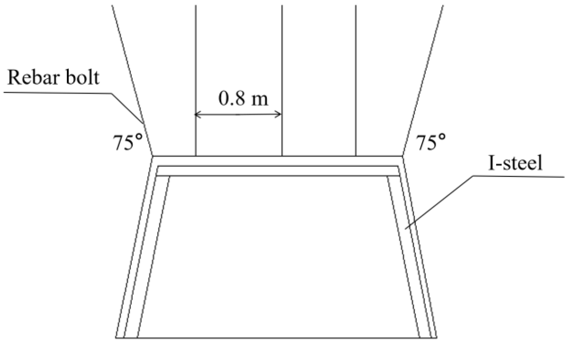
(3)
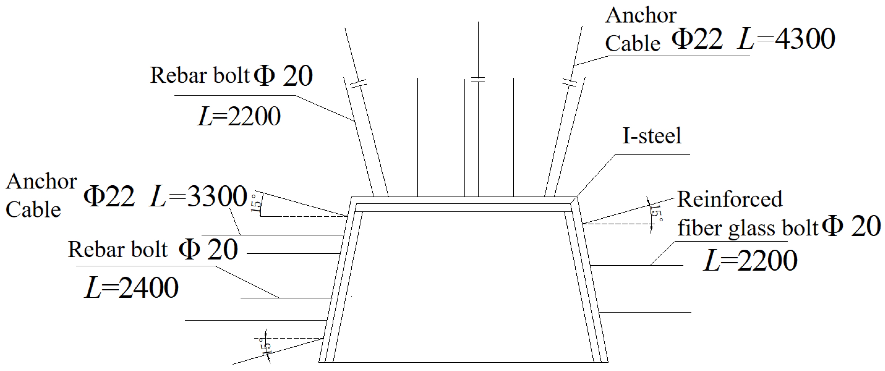
The asymmetric anchor cable + I-steel support scheme is proposed to effectively prevent the deformation and fracture of the roadway roof in this study. And the bolt-cable timely support plays a controlling role on the surrounding rock of the roadway. In addition, the plastic zone of the surrounding rock of the roadway is the least, and the bearing capacity of surrounding rock in the roadway increases from 0–2 MPa to 2–4 MPa.
(4)
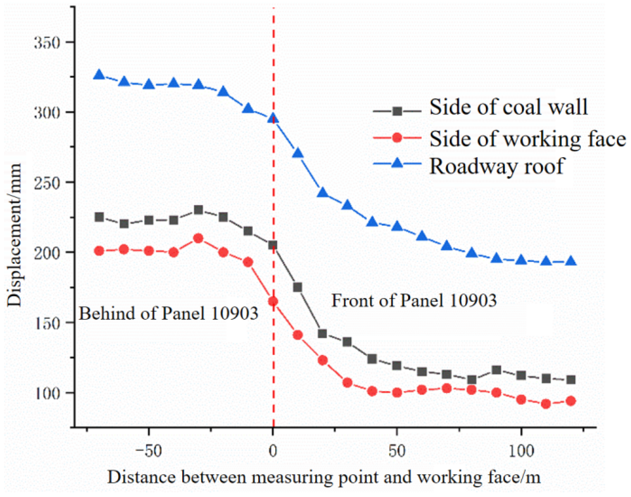
Through the field observation of the surrounding rock deformation of the roadway in the test section, the maximum displacement of the roadway roof, coal pillar side and working face side is 326 mm, 225 mm and 201 mm, respectively. Moreover, the deformation on both sides of the roadway is asymmetric in distribution, and its deformation rate is the largest in the range of +20 m to −40 m from the working face. The overall displacement of the roadway is within the controllable range as a result of using the optimized support scheme.
The finite difference method in numerical simulation has a certain limitation to simulate the practice situations of background engineering. In addition, further research should also consider the influence of temperature and humidity on the strength of rock mass, especially for the coal seam under a large buried depth.

Author Contributions

Y.S.: Formal analysis, Numerical simulation, Experimental test, Writing—Original draft; D.K.: Data curation, Methodology, Writing—Original draft, Numerical Simulation, Experimental test, Funding acquisition; S.P.: Formal analysis, Investigation; Y.X.: Numerical simulation, Experimental test; Q.L.: Data curation, Numerical simulation, Experimental test; Z.C.: Formal analysis, Methodology, Validation, Writing—Review and editing. All authors have read and agreed to the published version of the manuscript.

Funding

This research was funded by the National Natural Science Foundation of China (No. 52164002, 52164005, 52064005 and 51904082); And this Supported by Guizhou Provincial Science and Technology Projects (Qianke Science Support [2021] General 399). The authors would also like to thank the editors and anonymous reviewers for their valuable time and suggestions.

Institutional Review Board Statement

Not applicable.

Informed Consent Statement

Not applicable.

Data Availability Statement

All data used during the study appear in the submitted article.

Conflicts of Interest

The authors declare no conflict to interest.

References

  1. Kong, D.; Cheng, Z.; Zheng, S. Study on the failure mechanism and stability control measures in a large-cutting-height coal mining face with a deep-buried seam. Bull. Eng. Geol. Environ. 2019, 78, 6143–6157. [Google Scholar] [CrossRef]
  2. Xiong, Y.; Kong, D.; Cheng, Z.; Wu, G.; Zhang, Q. The Comprehensive Identification of Roof Risk in a Fully Mechanized Working Face Using the Cloud Model. Mathematics 2021, 9, 2072. [Google Scholar] [CrossRef]
  3. Liu, F.; Guo, Z.; Lv, H.; Cheng, Z. Test and analysis of blast wave in mortar test block. Int. J. Rock Mech. Min. Sci. 2018, 108, 80–85. [Google Scholar] [CrossRef]
  4. Klemetti, T.M.; Van Dyke, M.A.; Evanek, N.; Compton, C.C.; Tulu, I.B. Insights into the Relationships Among the Roof, Rib, Floor, and Pillars of Underground Coal Mines. Min. Met. Explor. 2021, 38, 531–538. [Google Scholar] [CrossRef]
  5. Maleki, H. Coal pillar mechanics of violent failure in U.S. Mines. Int. J. Min. Sci. Technol. 2017, 27, 387–392. [Google Scholar] [CrossRef]
  6. Xue, Y.; Liu, J.; Ranjith, P.G.; Zhang, Z.; Gao, F.; Wang, S. Experimental investigation on the nonlinear characteristics of energy evolution and failure characteristics of coal under different gas pressures. Bull. Eng. Geol. Environ. 2022, 81, 38. [Google Scholar] [CrossRef]
  7. Xie, J.; Xu, J.; Wang, F.; Guo, J.; Liu, D. Deformation effect of lateral roof roadway in close coal seams after repeated mining. Int. J. Min. Sci. Technol. 2014, 24, 597–601. [Google Scholar] [CrossRef]
  8. Kong, D.; Xiong, Y.; Cheng, Z.; Wang, N.; Wu, G.; Liu, Y. Stability analysis of coal face based on coal face-support-roof system in steeply inclined coal seam. Geomech. Eng. 2021, 25, 233–243. [Google Scholar] [CrossRef]
  9. Lv, H.; Cheng, Z.; Dong, Y.; Zhang, J.; Ma, Y. Numerical simulation on the crack initiation and propagation of coal with combined defects. Struct. Eng. Mech. 2021, 79, 237–245. [Google Scholar] [CrossRef]
  10. Xue, Y.; Liu, J.; Liang, X.; Wang, S. Ecological risk assessment of soil and water loss by thermal enhanced methane recovery: Numerical study using two-phase flow simulation. J. Clean. Prod. 2022, 334, 130183. [Google Scholar] [CrossRef]
  11. Xiong, Y.; Kong, D.; Cheng, Z.; Wen, Z.; Ma, Z.; Wu, G.; Liu, Y. Instability Control of Roadway Surrounding Rock in Close-Distance Coal Seam Groups under Repeated Mining. Energies 2021, 14, 5193. [Google Scholar] [CrossRef]
  12. Zhang, Y.; Cheng, Z.; Lv, H. Study on failure and subsidence law of frozen soil layer in coal mine influenced by physical conditions. Geomech. Eng. 2019, 18, 97–109. [Google Scholar] [CrossRef]
  13. Liu, X.; Cheng, Z. Changes in subsidence-field surface movement in shallow-seam coal mining. J. S. Afr. Inst. Min. Metal. 2019, 119, 201–206. [Google Scholar] [CrossRef] [Green Version]
  14. Singh, S.K.; Agrawal, H.; Singh, A.P. Rib stability: A way forward for safe coal extraction in India. Int. J. Min. Sci. Technol. 2017, 27, 1087–1091. [Google Scholar] [CrossRef]
  15. Lv, H.; Cheng, Z.; Liu, F. Study on the mechanism of a new fully mechanical mining method for extremely thick coal seam. Int. J. Rock Mech. Min. Sci. 2021, 142, 104788. [Google Scholar] [CrossRef]
  16. Cheng, Z.; Geng, X. Soil consistency and interparticle characteristics of various biopolymer types stabilization of clay. Geomech. Eng. 2021, 27, 103–113. [Google Scholar] [CrossRef]
  17. Liu, X.; Ning, J.; Tan, Y.; Xu, Q.; Fan, D. Coordinated supporting method of gob-side entry retainingin coal mines and a case study with hard roof. Geomech. Eng. 2018, 15, 1173–1182. [Google Scholar] [CrossRef]
  18. Yu, J.; Liu, G.; Cai, Y.; Zhou, J.; Liu, S.; Tu, B. Time-Dependent Deformation Mechanism for Swelling Soft-Rock Tunnels in Coal Mines and Its Mathematical Deduction. Int. J. Geomech. 2020, 20, 04019186. [Google Scholar] [CrossRef]
  19. Lv, H.; Tang, Y.; Zhang, L.; Cheng, Z.; Zhang, Y. Analysis for mechanical characteristics and failure models of coal specimens with non-penetrating single crack. Geomech. Eng. 2019, 17, 355–365. [Google Scholar] [CrossRef]
  20. Cheng, Z.; Li, L.; Zhang, Y. Laboratory investigation of the mechanical properties of coal–rock combined body. Bull. Eng. Geol. Environ. 2020, 79, 1947–1958. [Google Scholar] [CrossRef]
  21. Cheng, Z.; Pan, W.; Li, X.; Sun, W. Numerical simulation on strata behaviours of TCCWF influenced by coal-rock combined body. Geomech. Eng. 2019, 19, 269–282. [Google Scholar] [CrossRef]
  22. Cheng, Z.; Yang, S.; Li, L.; Zhang, L. Support working resistance determined on top-coal caving face based on coal-rock combined body. Geomech. Eng. 2019, 19, 255–268. [Google Scholar] [CrossRef]
  23. Wang, D.; Barakos, G.; Cheng, Z.; Mischo, H.; Zhao, J. Numerical simulation of pressure profile of mining backfill fly-ash slurry in an L-shaped pipe using a validated Herschel-Bulkley model. J. Sustain. Cem. Based 2021, 1–15. [Google Scholar] [CrossRef]
  24. Wang, Y.; Wu, G.; Liu, Y.; Cheng, Z. Study on Overlying Strata Movement and Surface Subsidence of Coal Workfaces with Karst Aquifer Water. Mathematics 2022, 10, 169. [Google Scholar] [CrossRef]
  25. Yang, S.; Chen, M.; Jing, H.; Chen, K.; Meng, B. A case study on large deformation failure mechanism of deep soft rock roadway in Xin’An coal mine, China. Eng. Geol. 2017, 217, 89–101. [Google Scholar] [CrossRef]
  26. Lv, H.; Wang, D.; Cheng, Z.; Zhang, Y.; Zhou, T. Study on mechanical characteristics and failure modes of coal-mudstone combined body with prefabricated crack. Mathematics 2022, 10, 177. [Google Scholar] [CrossRef]
  27. Wang, D.; Cheng, Z.; Shi, Q.; Zhao, J.; Mischo, H. Simulation Study of the Velocity Profile and Deflection Rate of Non-Newtonian Fluids in the Bend Part of the Pipe. Geofluids 2022, 2022, 7885556. [Google Scholar] [CrossRef]
  28. Xu, C.; Xia, C. A new large strain approach for predicting tunnel deformation in strain-softening rock mass based on the generalized Zhang-Zhu strength criterion. Int. J. Rock Mech. Min. 2021, 143, 104786. [Google Scholar] [CrossRef]
Figure 1. Arrangement of multi-working faces.
Mathematics 10 02166 g001
Figure 2. Arrangement of working face 10905.
Mathematics 10 02166 g002
Figure 3. Previous support scheme of return airway of working face 10905.
Mathematics 10 02166 g003
Figure 4. Deformation of surrounding rock during roadway excavation.
Mathematics 10 02166 g004
Figure 5. Drilling images of a borehole at different distances from roadway roof. (a) 2.5 m. (b) 3.0 m. (c) 3.5 m. (d) 4.0 m.
Mathematics 10 02166 g005
Figure 6. Drilling images of a borehole at different distances from coal pillar side of roadway. (a) 1.5 m. (b) 2.0 m. (c) 2.5 m. (d) 3.0 m.
Mathematics 10 02166 g006
Figure 7. Drilling images of a borehole at different distances from working face side. (a) 1.5 m. (b) 2.0 m. (c) 2.5 m. (d) 3.0 m.
Mathematics 10 02166 g007
Figure 8. Mechanical model based on elastic-plastic theory.
Mathematics 10 02166 g008
Figure 9. Surrounding rock yield failure of working face.
Mathematics 10 02166 g009
Figure 10. Numerical simulation model.
Mathematics 10 02166 g010
Figure 11. Vertical stress distribution of surrounding rock in lower coal seam #9. (a) Advancing 20 m. (b) Advancing 40 m. (c) Advancing 60 m. (d) Advancing 80 m.
Mathematics 10 02166 g011
Figure 12. Plastic zone of coal seam #9 with different advancing distances. (a) Advancing 20 m. (b) Advancing 40 m. (c) Advancing 60 m. (d) Advancing 80 m.
Mathematics 10 02166 g012aMathematics 10 02166 g012b
Figure 13. Model excavation scheme.
Mathematics 10 02166 g013
Figure 14. Influence of excavation disturbance on upper coal seam.
Mathematics 10 02166 g014
Figure 15. Influence of adjacent roadway excavation disturbance.
Mathematics 10 02166 g015
Figure 16. Influence of excavation disturbance on this roadway.
Mathematics 10 02166 g016
Figure 17. Displacement of roadway. (a) Displacement of roadway roof. (b) Displacement of roadway floor. (c) Displacement of roadway in working face side. (d) Displacement of roadway in coal pillar side.
Mathematics 10 02166 g017
Figure 18. Roadway section support scheme.
Mathematics 10 02166 g018
Figure 19. Plastic zone and stress diagram of surrounding rock in two support schemes. (a) Plastic zone of original support scheme. (b) Vertical stress of original support scheme. (c) Plastic zone of proposed support scheme. (d) Vertical stress of proposed support scheme.
Mathematics 10 02166 g019
Figure 20. Layout of monitoring points.
Mathematics 10 02166 g020
Figure 21. Displacement curve of the surrounding rock of the roadway.
Mathematics 10 02166 g021
Figure 22. Support effect of return airway in working face 10905. (a) Return airway after support. (b) test section.
Mathematics 10 02166 g022
Table 1. Physical and mechanical properties of coal and rock mass.
Rock NameVolumetric Weight g/cm3Compressive Strength/MPaTensile Strength/MPaPoisson’s RatioCohesion/MPaInternal Friction Angle/°
Coal #61.2913.250.330.321.1825.16
Mudstone-12.1338.900.880.311.7823.40
Argillaceous Sandstone2.3279.651.570.283.8034.00
Silty Mudstone2.4462.181.230.213.3030.05
Coal #91.3011.890.260.361.4224.50
Mudstone-22.0038.200.820.291.8024.00
Publisher’s Note: MDPI stays neutral with regard to jurisdictional claims in published maps and institutional affiliations.

