1. Introduction
Nanotechnology and nanoengineering have piqued the curiosity of many scientists and engineers in recent decades. The use of ferrofluids is one of the most effective and crucial ways to transfer heat in this new area of nanoscience, as such fluids have superior thermal conductivity compared to regular fluids [
1].
Forming a ferrofluid, also known as magnetic fluid, by dispersing ferroparticles in a non-magnetic base fluid (typically water, kerosene, or oil) can significantly enhance the thermal and rheological properties when subjected to a magnetic field [
2,
3,
4]. The thermophysical properties are very sensitive to the magnetic field strength and direction [
1].
The use of an external magnetic field to manage heat transfer fluxes in ferrofluids is known as thermomagnetic convection. This kind of convection can be significantly greater than natural convection and may be leveraged to improve the performance of cooling systems [
1]
The application of a magnetic field may either enhance or disrupt the fluid flow and heat transfer, resulting in a continuous convection of heat in a magnetized ferrofluid that has an uneven temperature distribution. The adequate use of magnetic convection in ferrofluids, where the magnetization changes in the ferrofluid due to temperature gradients, may increase the performance of small-scale cooling mechanisms [
5].
With the development of better magnetic coils and permanent magnets, much effort has been made to approach effective cooling based on ferrofluid convection. Nakatsuka et al. [
6] studied the heat transfer properties of a heat pipe containing a water-based magnetic fluid and found that a non-uniform magnetic field increased heat transfer efficiency by 13%. Kumar et al. [
7] investigated the influence of the intensity of a self-induced magnetic field surrounding a current-carrying wire on thermomagnetic convection cooling in ferrofluid using both experimental and computational methods. This comparative study showed that the cooling was due to the self-induced magnetic field interacting with the magnetic fluid, rather than natural convection or other nanofluid-related mechanisms.
Combined natural and thermomagnetic convection in cavities, on the other hand, has gained a lot of attention from researchers because of the many potential applications, making it advantageous compared to natural convection alone [
8,
9,
10].
The natural convection heat transfer properties of a diester-based ferrofluid under a permanent magnet effect in a channel with a constant cross-section, in which the bottom wall is heated and the top wall cooled, were studied by Cheng et al. [
11]. The measurement of the effect of cooling temperatures on the thermal behavior of ferrofluids was done in a simplified model of a magnetic fluid seal. The permanent magnetic field and temperature gradient influence the ferrofluid’s convective heat transfer. As a result of the temperature gradient, both natural convection and thermomagnetic convection are generated. The heterogeneous distribution of the Kelvin force is caused by the non-uniform magnetic field, which, in turn, causes thermomagnetic convection.
Khedher et al. [
12] numerically analyzed the behavior of a magnetic nanoliquid under the influence of Brownian diffusion inside a cavity with two local heaters and two magnetic sources. The findings demonstrated that an increase in the upper magnetic source power reflects an increase in the thermal diffusive zone in the upper half of the cavity as the ratio of the strengths of the magnetic sources rises. In a revolving enclosure with magnetic fins, the rate of heat conduction through a cooling fin is significantly influenced by the Kelvin body force produced on oxygen atoms by the fin [
13]. The Nusselt number increases by 5% in a magnetic field with a residual magnetic flux density of 5.0 T. However, gravitational convection dominates in a ferrofluid in the gap between two concentric cylinders, where the magnetic field formed by a current-carrying conductor is found to be inadequate to compete with gravitational convection [
14].
Recently, the thermomagnetic cooling performance of many magnetic cooling devices has been examined. Pattanaik et al. [
15] designed a novel magnetic cooling device for long-distance heat transfer. Experiments and numerical models were used to evaluate heat load cooling.
Wu et al. [
16] used an external magnetic field to induce the sliding movement of ferric oxide nanoparticles in an aqueous lithium bromide solution in order to increase the vapor absorption rate. The experimental findings suggest that employing this strategy increases the vapor absorption rate significantly. The average absorption rates attained with the magnetic field effect were 1.58 times greater than those achieved without it. The findings suggest that using a nanofluid may improve the vapor absorption process. Particle image velocimetry data were used by Lian et al. [
17] to quantify the velocity of a ferrofluid in a flow channel.
The development of novel cooling systems based on thermomagnetic convection demonstrates the relevance of prior research in this field in achieving this goal. However, further research is needed to better understand this issue and to maximize both the thermomagnetic and natural convections inside cooling systems of various shapes and configurations. This study aims to investigate the effects of the presence of a permanent magnet on the magnetic-gravitational heat transfer convection of a non-Newtonian ferrofluid in a cylindrical cavity. The goal of this research is to see how the non-Newtonian nature of a ferrofluid and the magnet dimension influence the flow and thermal fields, as well as the rate of heat transfer. The geometry used in this study is suggested as a way to examine and enhance the advantages of the magneto ferrofluid. Finally, in the studied geometry, the effects of the location and arc size of the hot and cold walls in the presence of the permanent magnet are investigated.
2. Problem Definition
This work deals with the convection flow of a power law non-Newtonian fluid which is influenced by the buoyancy forces resulting from a permanent magnet and gravity.
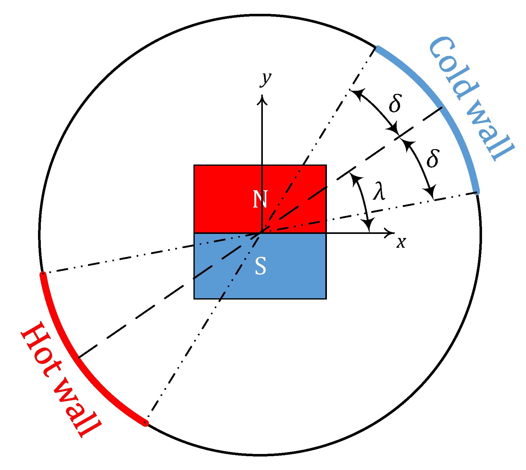
Figure 1 depicts the computational domain along with the defined Cartesian coordinate system. The domain is a circular enclosed medium having a diameter,
. The higher and lower temperatures
and
are imposed on the left and right arcs of the circular enclosure with a length of
. The diameter passing through the middle of the cold sector forms an angle
with respect to the defined
-axis. A permanent magnet of length
applies the magnetic field of strength
to the ferrofluid. The surfaces of the magnet, located in the center of the enclosure, are adiabatic. The ferrofluid flow is considered to be steady, incompressible and laminar. The electronic current due to the movement of the magnetic flow may be neglected. Density changes are ignored except in the buoyancy term, which is estimated by the Boussinesq linear approximation.
The variables listed in Equation (1) are used to normalize the controlling equations, where is the component of velocity in the -direction, is the component of velocity in the -direction, is thermal diffusivity, is pressure and is the density of the fluid. is magnetic field strength, B is magnetic flux density and is magnetization (magnetic moment per unit volume) of the fluid. The subscripts , , and mean dimensionless, with dimensions, remanent and saturation, respectively. is the permeability of free space.
Applying the dimensionless variables shown in Equation (1), i.e.,
,
,
,
and
, the controlling equations in dimensionless coordinates may be expressed as in Equations (2)–(4). Equations (5)–(8) define the variables
and the Prandtl (
), Rayleigh (
), Mach (
) and temperature (
) numbers for the magnetic ferrofluid. K is the thermal conductivity of the fluid, which has a specific heat capacity at constant pressure of
. Other variables are defined in subsequent equations.
The components of the magnetic field in dimensionless coordinates are given in the
-direction by Equation (9) and in the
-direction by Equation (10), where
in both cases. The dimensionless form of the magnetic field properties is given by the expressions in Equation (11), where
is the temperature number of the fluid defined in Equation (8) and
is the number of magnetic dipoles per unit volume.
4. Results and Discussion
The following parameters were studied in the ranges specified:
,
,
,
,
. The other parameters, which were kept fixed throughout the study, were
,
,
, and
.
Figure 4 shows the variation of the streamlines for power law indices,
, 1.0 and 1.3 and of the angle
when
,
,
,
,
,
, and
. All subfigures show two vorticities formed inside the circular cavity. For
, it is seen that the fluid velocity is greater for fluids with a lower power law index,
(
Figure 4). This is attributed to the fact that the viscosity of a fluid with a lower power law index is lower for a given state of flow, which allows the ferrofluid to flow faster under given conditions. Also, the center of the vorticities is closer to the cold wall, showing the tendency of the movement of the ferrofluid away from the hot region. As the angle
increases from
to
the center of the vorticities moves counterclockwise with the hot and cold regions of the wall. For the lower power-low index fluids, the centers of the vortices are closer together and a strong flow circulation is seen. For a high power-low index, such as
, the movement of the vorticities reduces as the friction force of the fluid increases.
Figure 5 shows the variations of the isotherm lines inside the circular cavity for different values of the angle,
, and power law index,
, when
,
,
,
,
,
and
. For each case, the isotherms are near vertical close to the hot sector of the cavity due to the dominance of the heat conduction in this area. Similar vertical isotherms are seen for all values of
when
. This is because the viscosity of the ferrofluid is higher in this case, and so more energy is dissipated due to the flow of the fluid. In turn, this leads to less flow overall and, therefore, less convection inside the circular cavity. Consequently, heat transfer is primarily by conduction for
. In the other cases, the circulation of the fluid is more apparent and thermo-magnetic convective heat transfer is significant.
The local Nusselt number is higher in the hot region of the cavity than the cold region (
Figure 6, where the “hot arc” and “cold arc” are those regions of the circumference of the cavity which have fixed temperatures
and
, respectively). The local Nusselt number represents the heat transfer at these zones. The rate of heat transfer close to the hot arc is higher than the cold one. For both arcs, the heat transfer rate increases considerably toward the ends of arcs, as in the middle region of each arc there is not much fluid displacement and so heat transfer is dominated by conduction. Conversely, in the end regions of the arcs, the movement of the fluid base and buoyancy effects causes the heat transfer to increase considerably. The greater the power law index, the lower the rate of heat transfer. This is the result of greater energy dissipation and correspondingly lower fluid flow and, so, convective heat transfer.
The average Nusselt number,
, inside the circular cavity does not change significantly as a function of the location of cold and hot arcs of the cavity wall, as given by the variable
(
Figure 7). However, for power law indices,
, the average Nusselt number shows a slight decrease as an increasing function of
, and for the power-low indices
and
, it exhibits a slight increase. The average Nusselt number,
, has its maximum value at
for all power law index values except
, which has a maximum at 90°. As mentioned previously, the lower power law indices result in less viscous energy dissipation, and so faster fluid flow. Therefore, the fluid with
(the lowest in this study) experiences the highest average Nusselt number, while
(greatest value) has the minimum value. For clarity,
Figure 7b shows the relative change in the average Nusselt number that are shown in
Figure 7a, compared to the base condition (
, at which the arcs are located on opposite sides of the cylinder to each other with their centers on the
-axis). This change is denoted as the variable
and is expressed as a percentage in
Figure 7b. As
increases up to
,
increases up to around +5%, indicating an increase in the rate of heat transfer. After this angle, fluids with a low power law indexes, i.e.,
and 0.8, keep increasing in heat transfer rate, albeit more slowly than at lower angles; however, those fluids with power index values of
show a decrease of average Nusselt number with increasing angle,
, up to
. It worth mentioning that although
decreases above
, it is never negative in the case of
, indicating that the lowest average Nusselt number for that case occurs when
.
Figure 8 and
Figure 9 demonstrate the effects of the thermal and magnetic Rayleigh numbers on the streamlines and temperature field inside the circular cavity when
,
,
,
,
,
and
. For a specific magnetic Rayleigh number, as the buoyancy Rayleigh number increases, the buoyancy force imposed on the fluid flow increases. This leads to stronger fluid flow and enhances the strength of the vortices inside the cavity. As the buoyancy Rayleigh number increases, the conductive area close to the hot and cold arcs diminishes, and the effect of the convective term increases due to the greater buoyancy effects. At a buoyancy Rayleigh number of
, the increase in the magnetic Rayleigh number leads to the increase of fluid flow circulation by Kelvin forces. The increase in the magnetic Rayleigh number enhances flow rotation and heat transfer. In terms of isotherms, an increase of the buoyancy Rayleigh number contributes to the smaller vertical area of the isotherms close to the hot and cold arcs, which implies that conduction is less important and free convection dominates. Also, the effect of the magnetic Rayleigh number on the isotherms in a specific buoyancy Rayleigh number is not significant.
Table 2 presents the effects of the magnetic and buoyancy Rayleigh numbers on the average Nusselt number inside the cavity. It is evident that both the magnetic and buoyancy Rayleigh numbers cause the average Nusselt number within the circular cavity to increase. The mechanism by which the magnetic Rayleigh number manifest itself is the circulation of the fluid flow, while the buoyancy Rayleigh number is concerned with the upward movement of the fluid due to buoyancy, causing intense fluid flow. When buoyancy effects are neglected (i.e.,
), only the Kelvin force is imposed on the fluid flow, and the average Nusselt number increases by approximately 100% as the magnetic Rayleigh number increases from
to
. There is a similar increase when the buoyancy Rayleigh number increases from
to
at constant magnetic Rayleigh number. However, for higher buoyancy Rayleigh numbers, such as
, the average Nusselt number decreases slightly when magnetic Rayleigh number increases.
Figure 10 shows the dependence of the flow streamlines and isotherms on the magnet size for two different Rayleigh numbers when
,
,
,
,
and
. The streamline at
(i.e., when buoyancy is neglected and only the Kelvin force is imposed on the fluid flow) shows that a stronger magnet helps the rotation of the fluid flow inside the circular cavity. There are two vorticities for
and
, while four vorticities are formed at
. However, as the space available for the fluid flow diminishes, since the (larger) magnet takes up more of the space in the cavity, the strength of the vorticities reduces at
. In terms of isotherms at this buoyancy Rayleigh number, the bigger magnet causes the dominant cooling mechanism to change from convection to conduction. At
, as in the previous case, a larger magnet limits the space for the flow rotation and movement, leading to the weaker vorticities. However, the buoyancy effect due to the higher Rayleigh number, causes the strength of the fluid circulation to increase considerably, compared to the case where there is no buoyancy force. This enhances the buoyancy-driven convective heat transfer inside the circular cavity.
Figure 11 shows the variations of the average Nusselt number due to different magnet sizes for the entire range of power law indexes at
and
. For the case of
, where buoyancy is not possible and so only the Kelvin force is imposed on the flow, the average Nusselt number varies from 0 to 6. It increases initially, as the magnet is made bigger, up to some size between
and
, depending on the power law index. Above this peak value, the average Nusselt number decreases. This is due to the limited space available for fluid flow when the magnet becomes large, which restricts heat transfer. Also, as is expected, low power law index values reduce the energy dissipation in the fluid, leading to more fluid flow and a high Nusselt number. The average Nusselt number when
is constant for magnet sizes up to
. Above this, fluids with a power law index of
exhibit an upward trend of average Nusselt number, while other fluids show a fall. The reason of this constant trend is that the buoyancy force is dominant compared to the Kelvin force for smaller magnets, while the influence of the Kelvin force dominates the buoyancy force at magnet sizes larger than
. The increase in average Nusselt number for power law index
is due to the low energy dissipation, even when the magnet is so large as to restrict the space for fluid flow. For fluid with the power-low exponent
, the high viscosity leads to significant energy dissipation, and therefore, low heat transfer and a corresponding low average Nusselt number.
Figure 12 shows streamlines and isotherms within the cavity for different angular sizes of the heated and cooled arcs,
. Two connected vorticities are formed at the left and right sides of the magnet, and as
increases, the strength of the flow increases within the cavity. In fact, when the arc size increases, more heat reaches the ferrofluid, and consequently, the flow strength grows. This flow strength is higher at the right side close to the cold arc of the cavity. Also, streamlines closer to the magnet show greater strength due to the positive effects of the magnet on the flow movement. The flow velocity is higher close to the colder side as the flow starts from the hot section (on the left of the domain) toward the cold one (on the right side). The numbers represented by the isotherms indicate the greater importance of convective heat transfer as δ increases. For example, when δ = 45°, the horizontal isotherms representing convective term occupy more area of the cavity, while for δ = 15°, this area is smaller, and the conductive term plays a major role in the heat transfer rate. The average Nusselt number for δ = 15°, 30°, 45°, and 60° is 13.18, 11.32, 10.22, and 9.37, respectively. When the heated surface expands (i.e., a larger value of
), the temperature gradient between the hot wall and the ferrofluid close to it decreases, leading to a lower rate of the heat transfer and a lower average Nusselt number.


 ,
, 


