Abstract
Thanks to their hovering and vertical take-off and landing abilities, quadrotor unmanned aerial vehicles (UAVs) are receiving a great deal of attention. With the diversified development of the functions of UAVs, the requirements for flight performance with higher stability and maneuverability are increasing. Aiming at parameter uncertainty and external disturbance, a deep deterministic policy gradient-based active disturbance rejection controller (DDPG-ADRC) is proposed. The total disturbances can be compensated dynamically by adjusting the controller bandwidth and the estimation of system parameters online. The tradeoff between anti-interference and rapidity can be better realized in this way compared with the traditional ADRC. The process of parameter tuning is demonstrated through the simulation results of tracking step instruction and sine sweep under ideal and disturbance conditions. Further analysis shows the proposed DDPG-ADRC has better performance.
Keywords:
reinforcement learning; deep deterministic policy gradient; active disturbance rejection control; quadrotor ummanned aerial vehicle MSC:
93-10
1. Introduction
Quadrotor unmanned aerial vehicles (UAVs) have attracted attention thanks to their ability to hovering and to take off and landing vertically. Due to their under-actuated nature, quadrotors’ position control is performed by controlling the attitude angles [1]. For this reason, attitude control of quadrotors has been a hot research topic in recent years. However, quadrotors are subject to parameter uncertainty and external disturbance, which threaten flight safety and pose huge challenges to the design of controllers [2]. In addition, with the popularity of quadrotors, higher requirements are being placed on the controllers. Thus, it is urgent to design an advanced controller to improve reliability and rapidity.
In the literature, plenty of approaches have been studied for the quadrotor attitude control problem. As a classical controller, proportion integration differentiation (PID) is widely used because of its simple structure and good control effect [3,4,5]. Taybe et al. [6] developed an augmented proportion differentiation (PD) attitude controller that guarantees exponential stability. Cao et al. [7] focused on the position control of quadrotors using an inner–outer loop control structure. The outer loop generates a saturated thrust, reference roll, and pitch angles, while the inner loop is designed to follow these reference angles using a traditional PID controller.
Due to nonlinearity and disturbances, the control effect of PID is unsatisfactory. As one of the most important control techniques, sliding mode control (SMC) is able to handle nonlinear systems with external disturbances. Based on second-order SMC, Zheng et al. [8] designed a controller for a small quadrotor unmanned aerial vehicle (UAV). Xiong et al. [9] designed a highly coupled and nonlinear controller for a fully actuated UAV through a novel robust terminal sliding mode control algorithm. Nevertheless, the oscillation caused by SMC is the main obstacle restricting its application.
To achieve robust performance and stabilization, the robust control method of George Zames has been widely studied [10]. Due to the uncertain nature of aircraft systems, Babar et al. [11] improved the traditional inner–outer loop strategy and adopted a robust controller for the inner control loop. Liu et al. [12] designed a distributed robust controller consisting of a position controller and an attitude controller for multiple quadrotors with nonlinearities and disturbances.
To deal with nonlinearities and disturbances, the main idea of active disturbance rejection control (ADRC) is to reduce the state feedback, whether linear or non-linear, to a cascade of integrators [13,14]. To solve the problem that UAV tracking control relies too much on mathematical modeling and the accuracy of measurements, Niu et al. [15] proposed a longitudinal pitching angle control system based on a nonlinear ADRC. Lotufo et al. [16] combined ADRC with embedded model control (EMC), relying on the disturbance rejector to bridge the gap between model and reality.
However, there are issues remaining that deserve attention [17].
- The classical controller design relies on understanding the physics of flight, and has difficulty to handling the coupling multiple loops design task. In other words, the classical one-loop-at-a-time design cannot guarantee success when more loops are added and coupled.
- Modern control techniques often require exact knowledge of models and are sensitive to parameter uncertainty and external disturbances [18]. However, different loads in each flight mission lead to uncertainty in system parameters. Meanwhile, parameters may be difficult to obtain, especially aerodynamic parameters. This sometimes leads to unstable behaviors, limiting the application of model-based controllers.
- For modern robust controllers [12], it is usually difficult to obtain the upper bounds of external disturbance and parameter uncertainty, which causes unsatisfactory performance.
- In the ADRC algorithm, the predefined bandwidth of the closed-loop system is unable to guarantee the tradeoff between robustness and transient tracking performance. Meanwhile, the estimation of parameters affects the ability of the controller to resist disturbances [14].
Aiming at the controller parameters tuning problem, many optimization algorithms have been used, including genetic algorithms (GA) [19], particle swarm optimization (PSO) [20], and grey wolf optimization (GWO) [21]. Bolandi et al. [22] used an analytical optimization method to tune a conventional PID controller for stabilization and disturbance rejection of quadrotors.
With the development of computer science and technology, reinforcement learning (RL) is able to autonomously learn optimal strategies through continuous interaction with the environment and is considered one of the most likely approaches for achieving general artificial intelligence [23]. Lee et al. [24] proposed an RL-based adaptive PID controller for dynamic positioning systems. The results showed that the system had better station-keeping performance without any deterioration in its control efficiency. Gheisarnejad et al. [25] proposed a deep deterministic policy gradient (DDPG)-based supplementary controller to enhance the adaptive capability of the tracking control problem. Zhao et al. [26] employed RL to update the optimal control weights in the fault-tolerant formation control law design. Zheng et al. [27] used the Q-learning algorithm to select the adaptive parameters for ADRC. However, as Q-learning can only deal with discrete problems, the states need to be stored in the Q table, and the action must be discrete. By itself, Q-learning cannot deal with complex continuous problems such as attitude control of UAVs. RL, which can solve the nonlinear optimal consensus control problem, is widely used in fault-tolerant control. Ma et al. [28] presented an adaptive model-free fault-tolerant control scheme based on integral RL by introducing the integral of the tracking error. Li et al. [29] designed direct adaptive optimal controllers by combining the backstepping technique with RL. The critic network is used to approximate the strategic utility functions and the action network is used to approximate the unknown and desired control input signals.
Motivated by the above discussions, ADRC based on DDPG is proposed in this paper. The main contributions of this paper are as follows:
- A realistic and nonlinear model of quadrotors is established, considering parameter uncertainty and external disturbances.
- Online continuous adjustment of the bandwidth of the closed loop is realized by DDPG, and is beneficial for balancing the robustness and transient tracking performance.
- DDPG is adopted to achieve fast and accurate compensation for the total disturbance of the system, leading to the response speed and control accuracy being further improved.
The remainder of this paper is organized as follows. In Section 2, the proposed dynamic quadrotor model with internal and external disturbances is provided. The proposed DDPG-based ADRC is presented in Section 3. The simulation results are provided and analyzed in Section 4. Finally, Section 5 presents our conclusions.
2. Nonlinear Model of Quadrotors
In this section, a nonlinear dynamic model with internal and external disturbances is provided. Figure 1 shows the structure and coordinate system of the quadrotor.
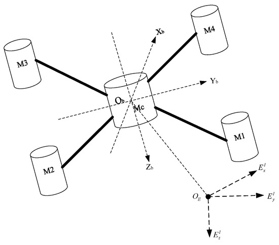
Figure 1.
Schematic of the quadrotor.
2.1. Ideal Model of Quadrotors
The ideal dynamic model of quadrotors is established in Formula (1).
where m is the quadrotor mass, is the position expressed in the Earth-inertial coordinate, denotes the rotation matrix from the body-fixed coordinate to the Earth-inertial coordinate, and is the force established in the body-fixed coordinate, where . is the lift coefficient and denotes the rotational speed of the rotor. Above, denotes the inertia matrix, while indicates the Euler angles, i.e., the roll, pitch, and yaw angles, respectively; thus, the rotation matrix can be rewritten using the Euler angles [12].
denotes the Coriolis term, where ;
represents the torque in the body-fixed coordinate
where . and d represent the distance from the motor to the center of mass and the anti-torque coefficient, respectively, while is the moment of inertia of the motors and propellers. For now, the normal model of quadrotors has been established.
2.2. Internal and External Disturbances
Quadrotors usually carry various mission payloads to perform different missions, resulting in changes in parameters such as mass or moment of inertia. This can be modeled as and , where and are the actual mass and inertia matrix, respectively, and and are the scaling factors of uncertainty. At the same time, quadrotors are inevitably disturbed by the environment, .
Thus, the actual dynamic model of quadrotors is expressed as follows:
3. Construction of DDPG-Based ADRC
3.1. ADRC-Based Attitude Controller Design
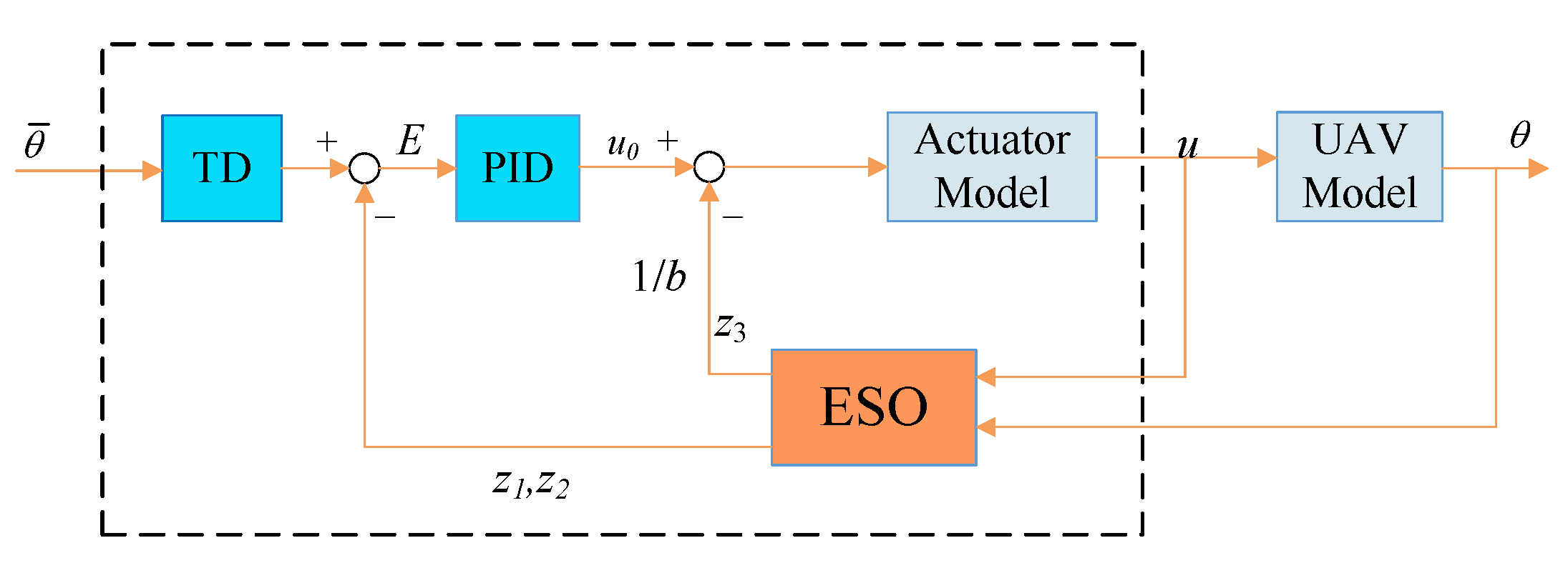
Only the attitude control of quadrotors is considered here, and the construction of ADRC is designed as in Figure 2. To facilitate the control system design, the quadrotor is reduced to a second-order system with perturbations, which can be written in state equation form:
where
h is the unknown disturbance, and .

Figure 2.
Structure of ADRC; is the desired angle of pitch and b is the estimation of system parameters.
Figure 2.
Structure of ADRC; is the desired angle of pitch and b is the estimation of system parameters.
The extended state observer (ESO) is designed from the ideal model of the quadrotor, which can be established as follows:
where y is the state of the system and L is the observer gain vector, .
It is obvious that the ESO is bounded-input bounded-output stable if the roots of the characteristic polynomial of
are all in the left half plane and h is bounded [14,30].
Thus, , , can be designed using the pole placement technique. Let . Therefore, it can be obtained that
where is the bandwidth of the observer.
For the controller, the ideal system can be written as , where . According to the proof above, the appropriate value (6) can make ; in other words, .
The controller is designed as . Thus, , where is designed as a PD controller, . It can be assumed that . Then, and the closed loop transfer function can be rewritten as
When , the closed-loop system is simplified into a standard second-order system.
Taken together, the effectiveness of the involved ESO and controller is demonstrated. Normally, , where is the bandwidth of the controller. In this paper,
However, as described in Section 2.2, when there are internal disturbances, B = in Formula (3) turns into . The difference between b and reduces the robustness of the system. The presence of the observer in ADRC allows the total disturbances to be observed, which means that . Then, the internal disturbance can be compensated for.
In practice, a step signal has a great impact on the system. To balance the contradiction between increasing the rapidity of the system and reducing the overshoot, a tracking differentiator (TD) can be adopted to track the desired signal, and a smooth tracking signal can be obtained and further used in the controller. In this paper, a standard second-order system is designed,
where is the natural frequency and is the damping ration.
3.2. Reinforcement Learning Theory
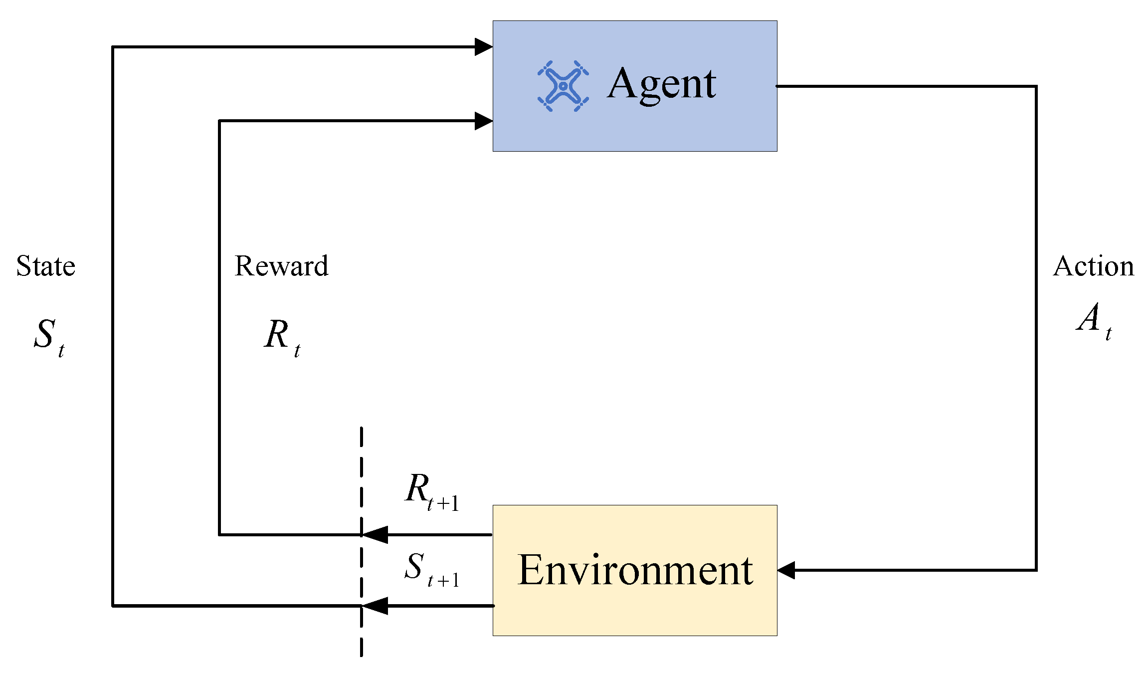
In this paper, the attitude control is regarded as a Markov decision process (MDP), which can be modeled as , where S represents the state space, A is the action space, is the state transition model, signifies the reward function, and is the discount factor. The MDP means that, at every timestep, the agent in state takes action , reward is obtained, and the state is transited to . A generic flowchart of the process is shown in Figure 3.
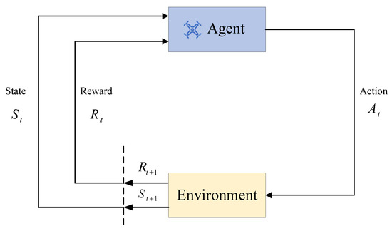
Figure 3.
Learning process of RL.
RL discusses how an agent can maximize its rewards in a complex and uncertain environment. The goal is to learn an optimal policy , which in all states enables the agent to obtain the maximum discount return ; the action-value function is called Q function, and can be rewritten using the Bellman equation:
where policy maps a state to action , which can be learned by an off-policy learning algorithm called Q-learning [31].
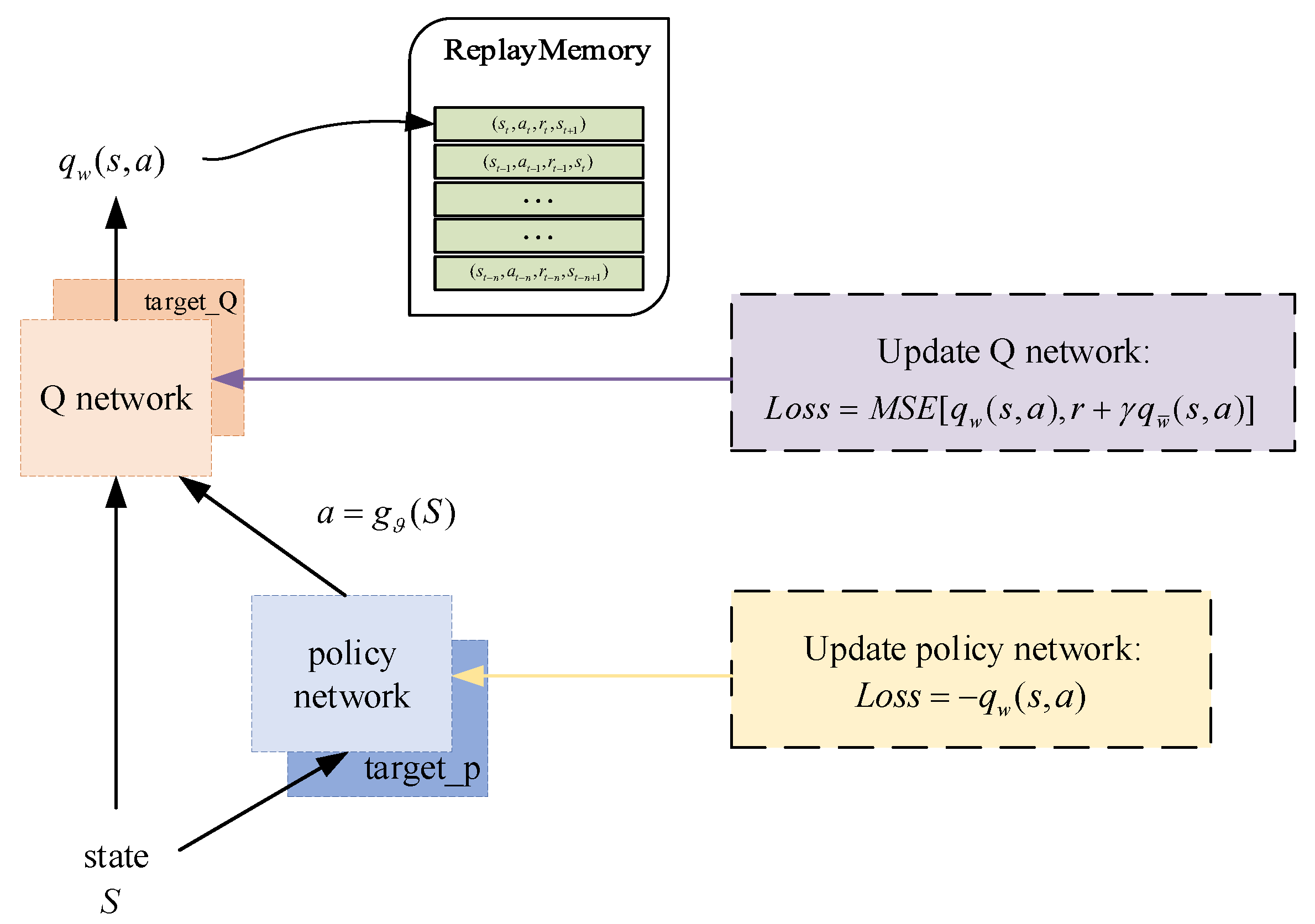
The strategy used in this paper is the DDPG algorithm, which is an extension of the deep Q network (DQN). A model-free algorithm that is able to operate over continuous action spaces has previously been presented in [32] based on the deterministic policy gradient. The structure is shown in Figure 4.
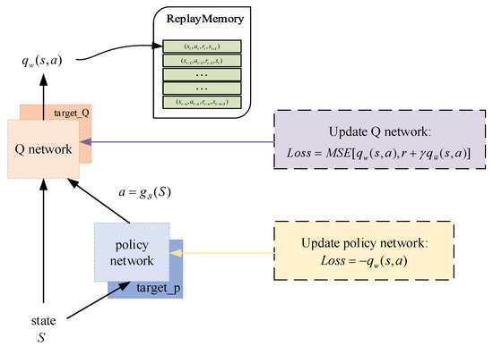
Figure 4.
The structure of DDPG.
Such a structure is called Actor–Critic. The policy network, which is called the Actor, outputs actions based on states . The Q network is employed to export the action value , which is named Critic, and a replay buffer is used to eliminate correlations between inputs. Compared with the Actor network, the Critic network usually has a more complex structure to infer the underlying state from the measurements and deal with the state transition [33].
3.3. Structure of DDPG-Based ADRC
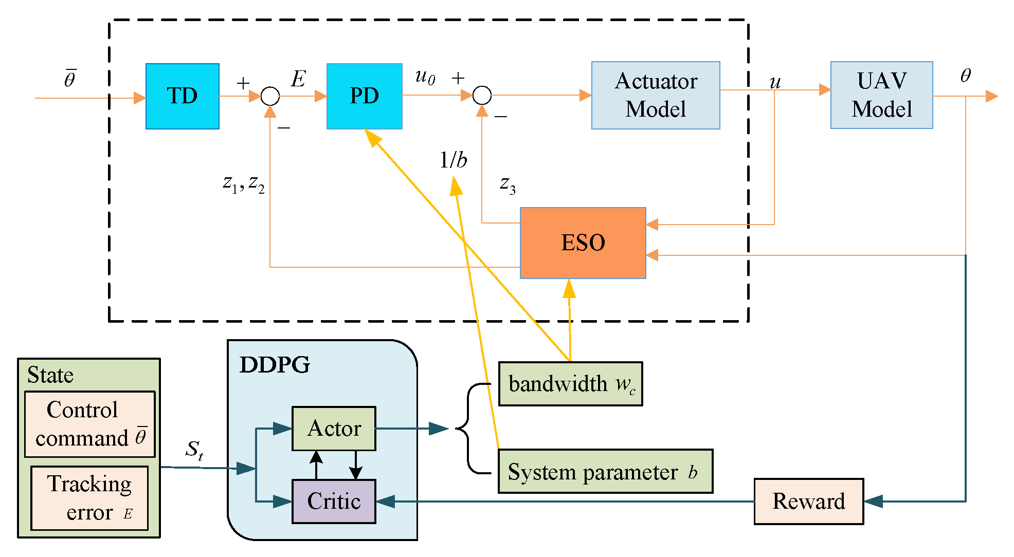
As a feedback-based controller, the inputs of DDPG-ADRC include the control command and the tracking error. Then, the outputs of DDPG are used to update the parameters in ADRC, which means the estimation of system parameters b and the bandwidth of the controller . On one hand, the parameter b reflects the gain from the input to the output of the system, which is related by the system parameters. On the other hand, to compensate for the total disturbance, is added to the PD controller, which means that b affects the compensation for disturbances. Meanwhile, the bandwidth of the controller, , directly determines the performance of the PD controller, and the bandwidth of the observer, , determines the performance of the ESO, where . An overall structure of the proposed fault-tolerant controller is shown in Figure 5.
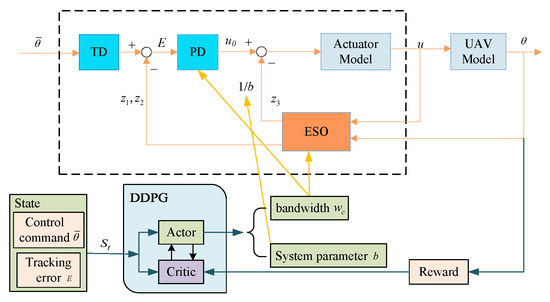
Figure 5.
Overall structure of the proposed DDPG-based ADRC controller.
The reward function is a key element in RL, supervising agents to learn and obtain the optimal policy. In order to solve the difficulty of training caused by sparse rewards, the reward function is designed as follows:
To solve the problem of slow convergence under small errors, step rewards are designed.
At the same time, a sparse penalty function is considered. When the attitude of the agent is too far away from the target, the current round of training is terminated in advance. To reduce ineffective exploration, a large penalty is introduced. Thus, the total reward is
Above all, the algorithm flow presented in this paper is shown in Algorithm 1.
The state input of DDPG is a two-dimensional vector, namely, control command, , and tracking error, e. The action output is a two-dimensional variable, i.e., b and .
| Algorithm 1 DDPG-based ADRC controller |
|
4. Simulation and Results
To verify the effectiveness of the proposed controller, simulations with ideal conditions and under conditions of internal and external disturbance are presented. The parameters of the quadrotor are shown in Table 1.

Table 1.
Quadrotor model parameters.
An Intel Xeon(R)W-2123 CPU @ 3.60 GHz, NVIDIA GeForce RTX1080Ti GPU, and Windows 10 64 bit were used in the experiments. To evaluate the performance of the proposed method several common evaluation indicators were adopted, such as integrated time and absolute error (ITAE), integrated time and square error (ITSE), and integrated absolute error (IAE).
These indicators take into account both the control accuracy and convergence speed; smaller values indicate better controller performance.
4.1. Simulations in the Presence of Internal Disturbances
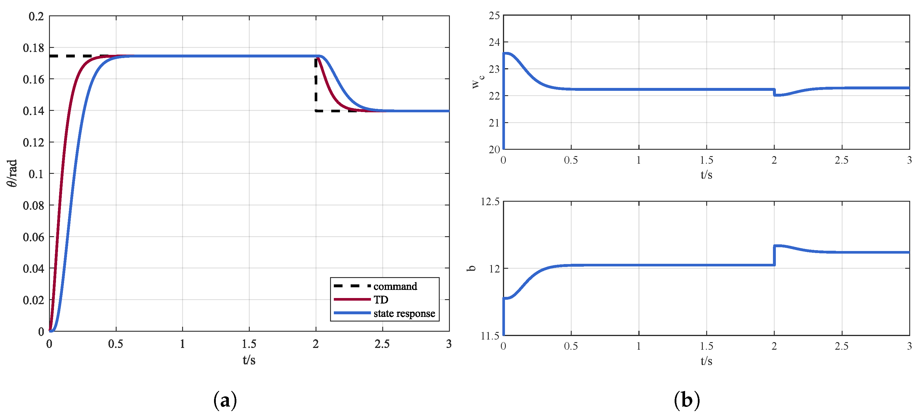
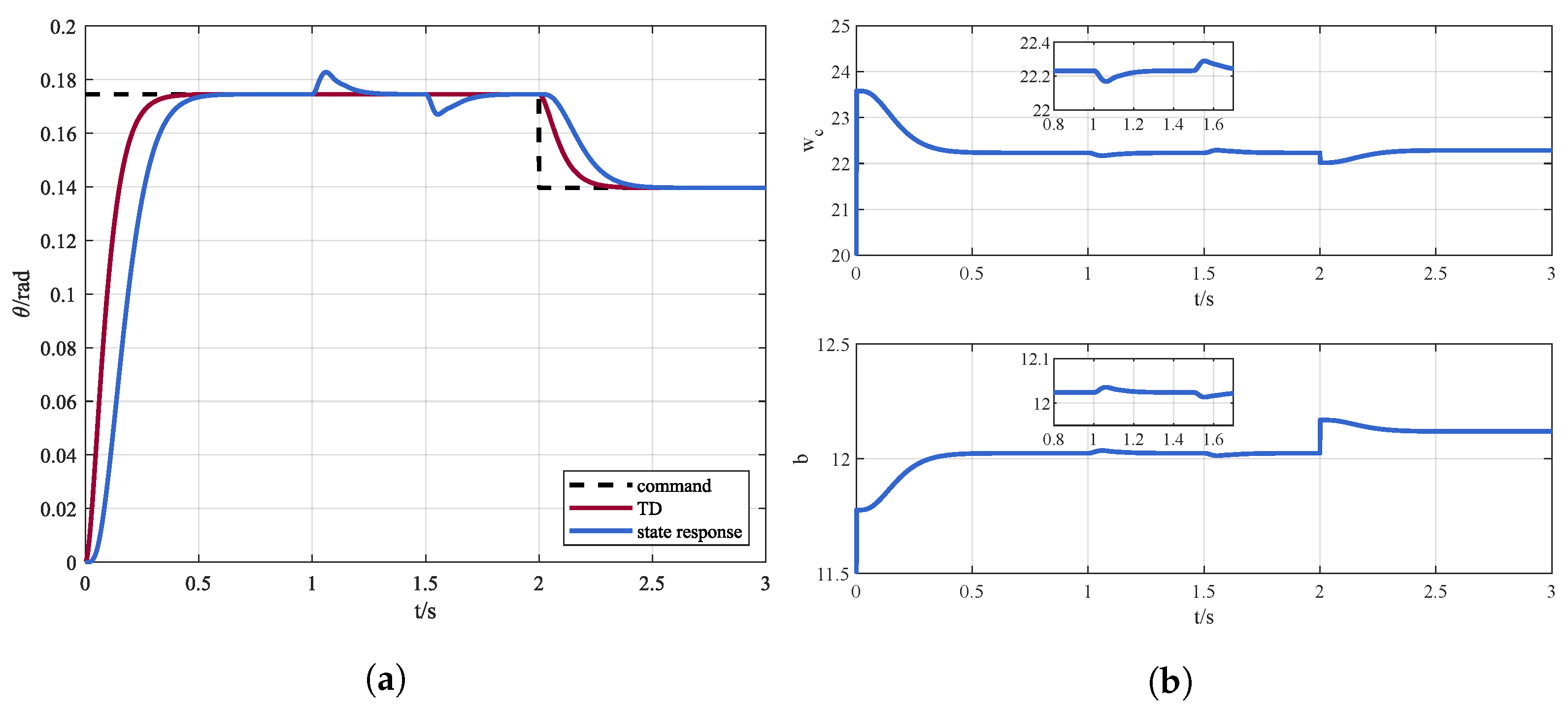
In order to verify the effectiveness of the proposed DDPG-ADRC method, simulations under internal disturbance conditions are presented. The pitch channel of the quadrotor tracks a step command of , and the command reduces to 2 s later. The response is shown in Figure 6a, and the outputs of RL, i.e, the bandwidth of the controller and the estimation of the system b are displayed in Figure 6b.
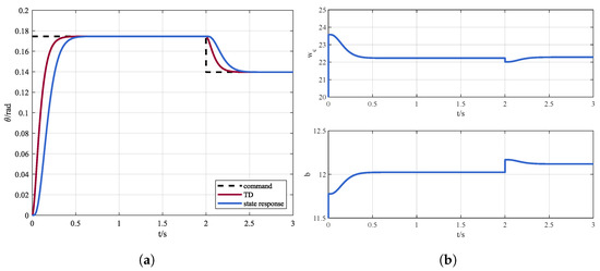
Figure 6.
(a) Control instruction and state response via DDPG-ADRC and (b) online parameters adjustment.
It can be seen that with DDPG-ADRC the quadrotor can accurately track the instruction. In addition, the controller bandwidth and the system parameter b can be adaptively adjusted according to the observations.
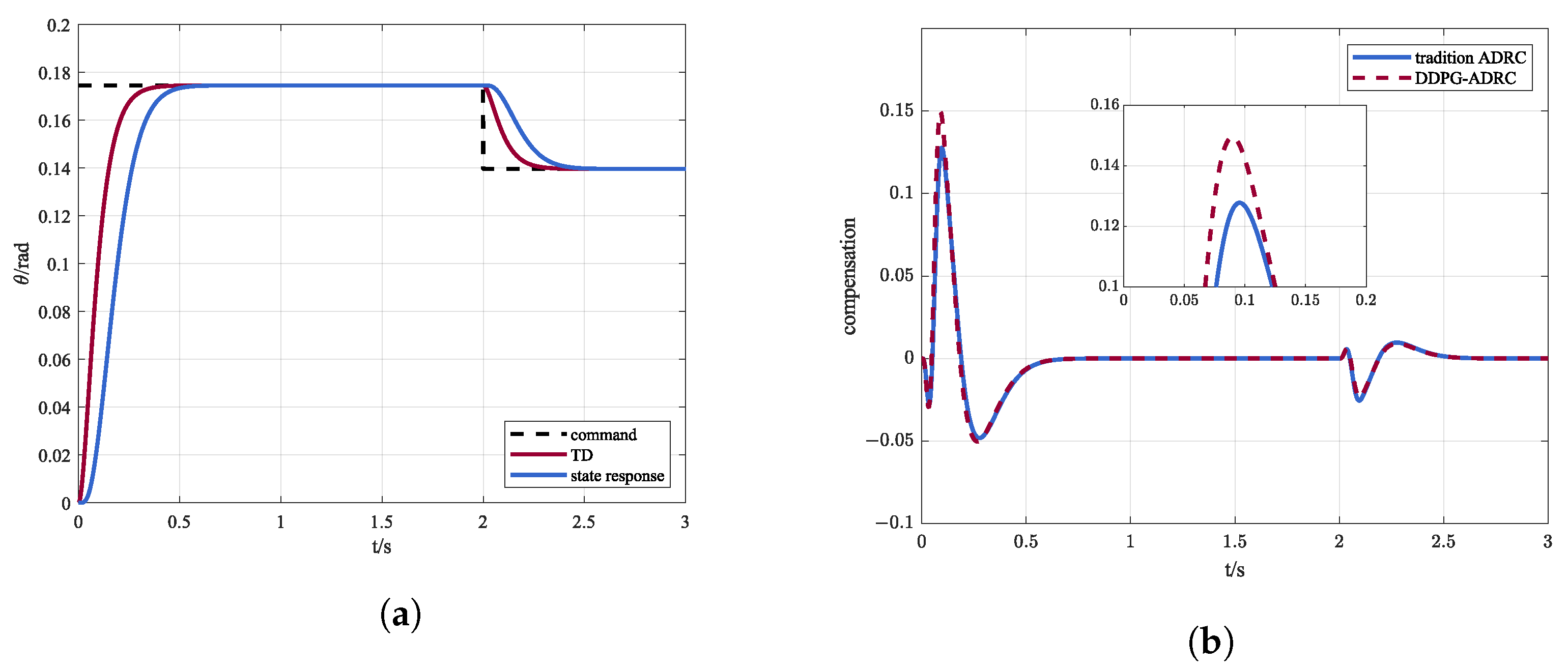
In order to demonstrate the advantages of dynamic parameter adjustment, the steady results are used as fixed parameters, i.e, . Figure 7a shows the response of the system and Figure 7b reveals the differences between traditional ADRC and DDPG-ADRC in compensating for total disturbances.
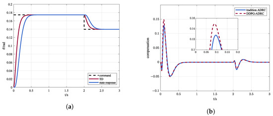
Figure 7.
(a) Control instruction and state response via traditional ADRC and (b) comparison of compensation amount between traditional ADRC and DDPG-ADRC.
By dynamically adjusting parameters, DDPG-ADRC can compensate for disturbances more accurately and quickly, which is the advantage of DDPG-ADRC compared to traditional ADRC.
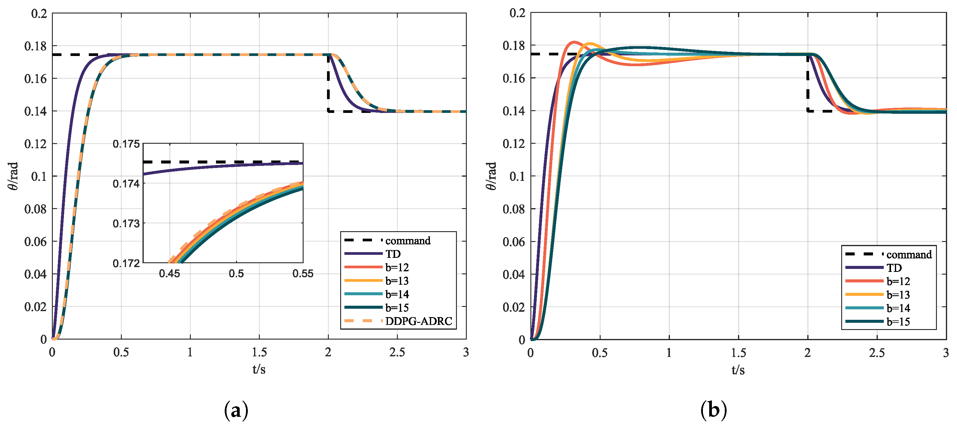
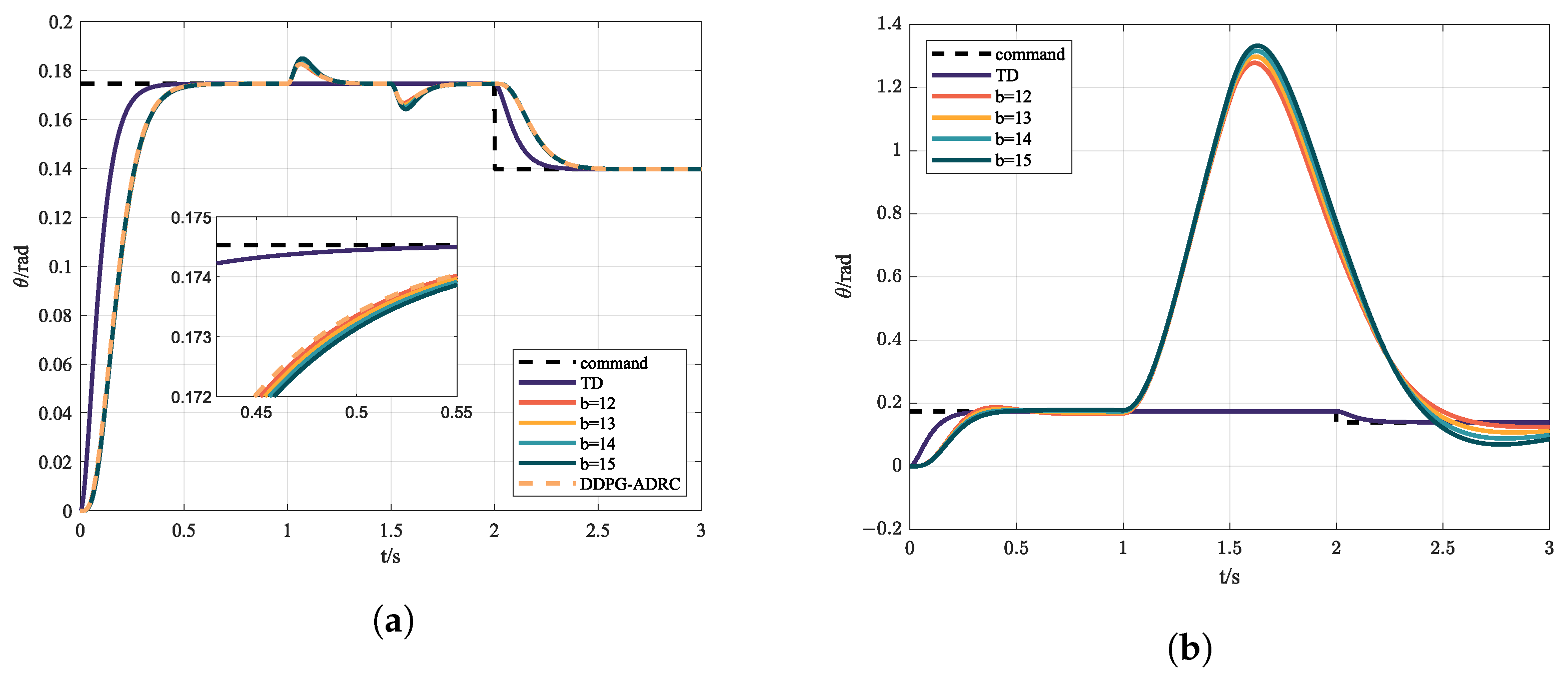
In order to explore the influence of parameter uncertainty on controllers, simulations were carried out with different parameter estimates b; the results are shown in Figure 8a, and are compared with model predictive control (MPC), shown in Figure 8b. In the design of the MPC controller, the same second-order system with a gain b is used. ITAE, ITSE, and IAE are adopted to evaluate the tracking process, and are shown in Table 2.
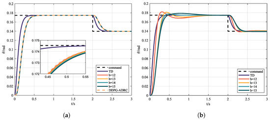
Figure 8.
(a) Control instruction and state response via ADRC with different b and (b) control instruction and state response via MPC with different b.
Table 2.
Evaluation indicators of MPC, traditional ADRC, and DDPG-ADRC.
It can be seen from Table 2 and Figure 8 that, under nominal conditions, all three controllers can achieve satisfactory control effect. Meanwhile, with the selection of appropriate parameters, with lower ITAE, ITSE, and IAE and higher rewards, the control effect of MPC is the best. However, MPC is less robust against parameter uncertainty compared with ADRC.
4.2. Simulations in the Presence of External Disturbances
In order to verify the performance of the proposed controller in the face of external disturbances, disturbance torque caused by windblast was added in the simulation time 1∼1.5 s. Figure 9a shows the control instruction and the response, and the action of RL is displayed in Figure 9b.
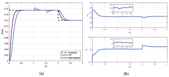
Figure 9.
(a) Control instruction and state response via DDPG-ADRC in the presence of external disturbances and (b) online parameters adjustment in the presence of external disturbances.
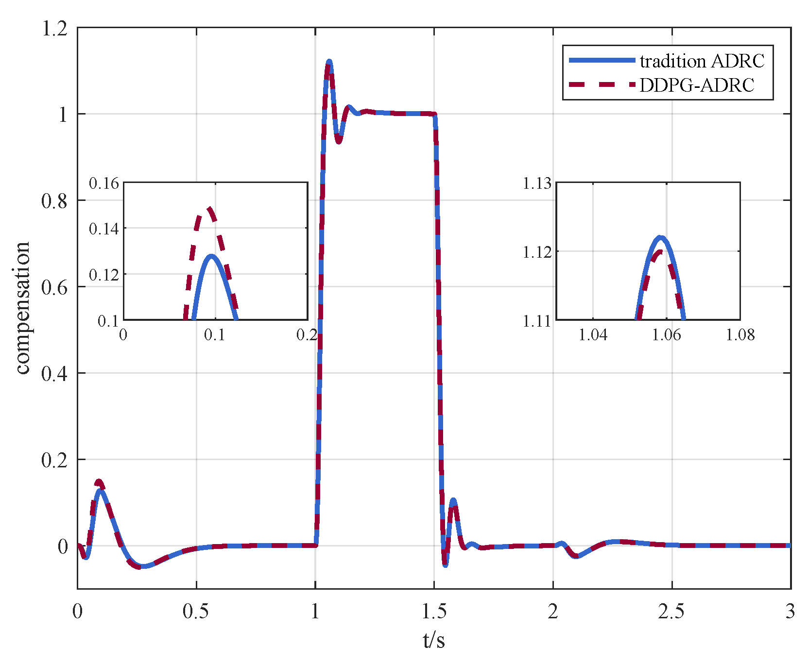
It can be seen that the designed DDPG-ADRC can respond in time when faced with external disturbances. The performance is compared with the traditional ADRC in Figure 10. The evaluation indicators are shown in Table 3.
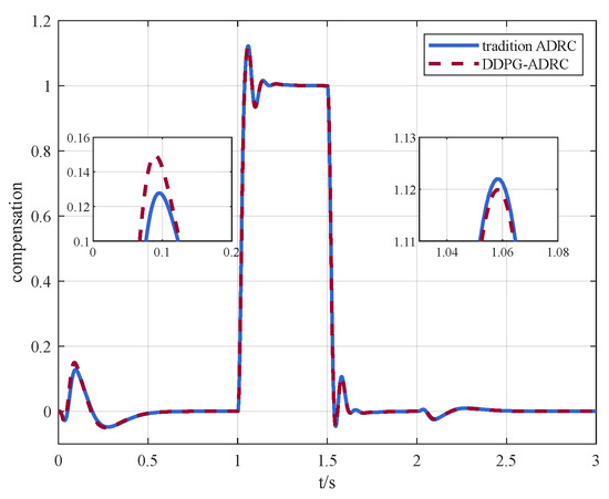
Figure 10.
Comparison of compensation between traditional ADRC and DDPG-ADRC in the presence of external disturbances.
Table 3.
Evaluation indicators of traditional ADRC and DDPG-ADRC in the presence of disturbances.
Compared with the case of internal disturbances shown in Table 3, external disturbances have a greater affect on controller performance, although both traditional ADRC and DDPG-ADRC can counteract the disturbances in time. Similarly, the performance of DDPG-ADRC is more prominent in both control accuracy and convergence speed. Under the ITSE indicator, DDPG-ADRC is improved by compared to ADRC in the presence of external disturbances. This means that DDPG-ADRC can achieve better performance than ADRC with fixed parameters in practice, which is demonstrated in Figure 11a as well. Although the MPC has better control performance under nominal conditions, it diverges when there are large external disturbances, as Figure 11b shows.
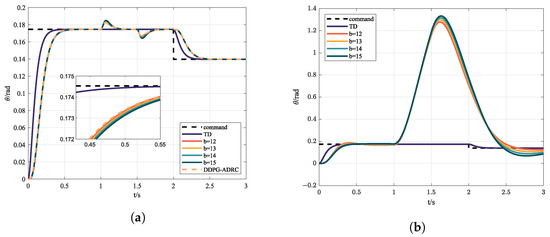
Figure 11.
(a) Control instruction and state response via ADRC with different b in the presence of external disturbances; (b) control instruction and state response via MPC with different b in the presence of external disturbances.
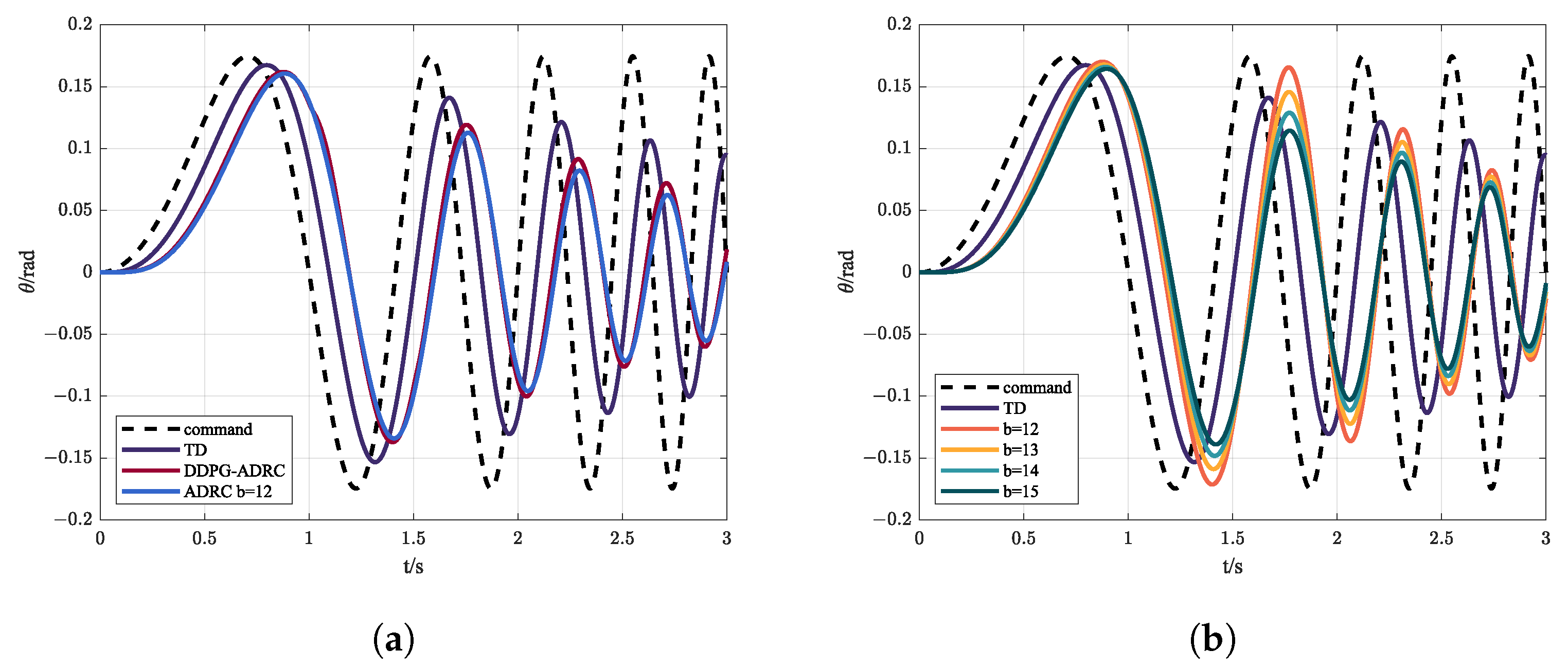
4.3. Simulation under Sine Sweep
In designing a control system, in order to know the response of the system under different frequency commands it is necessary to carry out frequency sweep experiments. A sine sweep is often used to measure the time-frequency characteristics of the system. Figure 12 shows the control instruction and response, while the evaluation indicators are shown in Table 4.
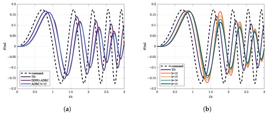
Figure 12.
(a) Control instruction and state response via ADRC and DDPG-ADRC under sine sweep; (b) control instruction and state response via MPC with different b under sine sweep.
Table 4.
Evaluation indicators of MPC, ADRC, and DDPG-ADRC.
It can be seen from Figure 12 and Table 4 that the uncertainty of the parameters affects the control effect of MPC; generally speaking, ADRC has better performance and lower phase delay in the high-frequency bound than MPC. Meanwhile, from the point of view of indicators, DDPG-ADRC has stronger tracking ability thanks to the adaptive adjustment of compensation.
5. Conclusions
In this paper, a novel DDPG-based ADRC is proposed for the attitude control of quadrotors. First, a nonlinear mathematical model of quadrotors with internal disturbance and external disturbance is established. Then, by properly setting the reward function, online continuous adjustment of the bandwidth is realized to balance the robustness and transient tracking performance. Meanwhile, fast and accurate compensation for the total disturbance is achieved, further improving the response speed and control accuracy. Simulation results show that DDPG-ADRC has advantages on all indicators; in other words, it has advantages in terms of both control accuracy and convergence speed. This paper provides a new solution to the attitude control of quadrotors in the presence of disturbances. In the future, the proposed controller will be used to conduct hardware-in-the-loop simulation experiments to further verify the stability of the algorithm. However, the gap between the simulation and the real world presents additional challenges, such as the oscillation of the controller [34].
Author Contributions
Conceptualization, J.S. and K.Z.; methodology, K.Z. and Y.H.; software, K.Z.; validation, K.Z., X.X. and Y.L.; formal analysis, J.S. and X.X.; investigation, K.Z. and Y.H.; resources, K.Z. and Y.L.; data curation, J.S.; writing—original draft preparation, K.Z.; writing—review and editing, K.Z.; visualization, K.Z.; supervision, J.S.; project administration, J.S.; funding acquisition, J.S. All authors have read and agreed to the published version of the manuscript.
Funding
This work was supported by the National Natural Science Foundation of China under Grants 61473015, 91646108, and 62073020.
Institutional Review Board Statement
Not applicable.
Informed Consent Statement
Not applicable.
Data Availability Statement
Not applicable.
Acknowledgments
The authors thank their colleagues for their constructive suggestions and research assistance throughout this study.
Conflicts of Interest
The authors declare no conflict of interest.
Abbreviations
The following abbreviations are used in this manuscript:
| UAV | unmanned aerial vehicle |
| PID | proportion integration differentiation |
| PD | proportion differentiation |
| SMC | sliding mode control |
| ADRC | active disturbance rejection control |
| EMC | embedded model control |
| GA | genetic algorithm |
| PSO | particle swarm optimization |
| GWO | grey wolf optimization |
| RL | reinforcement learning |
| DDPG | deep deterministic policy gradient |
| ESO | extended state observer |
| TD | tracking differentiator |
| MDP | Markov decision process |
| DQN | deep Q network |
| ITAE | integrated time and absolute error |
| ITSE | integrated time and square error |
| IAE | integrated absolute error |
| MPC | model predictive control |
References
- Tian, B.; Liu, L.; Lu, H.; Zuo, Z.; Zong, Q.; Zhang, Y. Multivariable finite time attitude control for quadrotor UAV: Theory and experimentation. IEEE Trans. Ind. Electron. 2017, 65, 2567–2577. [Google Scholar] [CrossRef]
- Liu, H.; Zhao, W.; Zuo, Z.; Zhong, Y. Robust control for quadrotors with multiple time-varying uncertainties and delays. IEEE Trans. Ind. Electron. 2016, 64, 1303–1312. [Google Scholar] [CrossRef]
- Hoffmann, G.M.; Huang, H.; Waslander, S.L.; Tomlin, C.J. Precision flight control for a multi-vehicle quadrotor helicopter testbed. Control Eng. Pract. 2011, 19, 1023–1036. [Google Scholar] [CrossRef]
- Mahony, R.; Kumar, V.; Corke, P. Multirotor aerial vehicles: Modeling, estimation, and control of quadrotor. IEEE Robot. Autom. Mag. 2012, 19, 20–32. [Google Scholar] [CrossRef]
- Pounds, P.; Mahony, R.; Corke, P. Modelling and control of a large quadrotor robot. Control Eng. Pract. 2010, 18, 691–699. [Google Scholar] [CrossRef] [Green Version]
- Tayebi, A.; McGilvray, S. Attitude stabilization of a VTOL quadrotor aircraft. IEEE Trans. Control Syst. Technol. 2006, 14, 562–571. [Google Scholar] [CrossRef] [Green Version]
- Cao, N.; Lynch, A.F. Inner–outer loop control for quadrotor UAVs with input and state constraints. IEEE Trans. Control Syst. Technol. 2015, 24, 1797–1804. [Google Scholar] [CrossRef]
- Zheng, E.H.; Xiong, J.J.; Luo, J.L. Second order sliding mode control for a quadrotor UAV. ISA Trans. 2014, 53, 1350–1356. [Google Scholar] [CrossRef]
- Xiong, J.J.; Zheng, E.H. Position and attitude tracking control for a quadrotor UAV. ISA Trans. 2014, 53, 725–731. [Google Scholar] [CrossRef] [PubMed]
- Zames, G.; Francis, B. Feedback, minimax sensitivity, and optimal robustness. IEEE Trans. Autom. Control 1983, 28, 585–601. [Google Scholar] [CrossRef]
- Babar, M.; Ali, S.; Shah, M.; Samar, R.; Bhatti, A.; Afzal, W. Robust control of UAVs using H∞ control paradigm. In Proceedings of the 2013 IEEE 9th International Conference on Emerging Technologies (ICET), Islamabad, Pakistan, 9–10 December 2013; IEEE: New York, NY, USA, 2013; pp. 1–5. [Google Scholar]
- Liu, H.; Ma, T.; Lewis, F.L.; Wan, Y. Robust formation control for multiple quadrotors with nonlinearities and disturbances. IEEE Trans. Cybern. 2018, 50, 1362–1371. [Google Scholar] [CrossRef] [PubMed]
- Song, J.; Zhao, M.; Gao, K.; Su, J. Error Analysis of ADRC Linear Extended State Observer for the System with Measurement Noise. IFAC-PapersOnLine 2020, 53, 1306–1312. [Google Scholar] [CrossRef]
- Gao, Z. Scaling and bandwidth-parameterization based controller tuning. In Proceedings of the 2003 American Control Conference, Denver, CO, USA, 4–6 June 2003; pp. 4989–4996. [Google Scholar]
- Niu, T.; Xiong, H.; Zhao, S. Based on ADRC UAV longitudinal pitching Angle control research. In Proceedings of the 2016 IEEE Information Technology, Networking, Electronic and Automation Control Conference, Chongqing, China, 20–22 May 2016; IEEE: New York, NY, USA, 2016; pp. 21–25. [Google Scholar]
- Lotufo, M.A.; Colangelo, L.; Perez-Montenegro, C.; Canuto, E.; Novara, C. UAV quadrotor attitude control: An ADRC-EMC combined approach. Control Eng. Pract. 2019, 84, 13–22. [Google Scholar] [CrossRef]
- Zuo, Z.; Liu, C.; Han, Q.L.; Song, J. Unmanned aerial vehicles: Control methods and future challenges. IEEE/CAA J. Autom. Sin. 2022, 9, 601–614. [Google Scholar] [CrossRef]
- Wang, X.; Van Kampen, E.J.; Chu, Q.; Lu, P. Stability analysis for incremental nonlinear dynamic inversion control. J. Guid. Control Dyn. 2019, 42, 1116–1129. [Google Scholar] [CrossRef] [Green Version]
- Mudi, J.; Shiva, C.K.; Mukherjee, V. Multi-verse optimization algorithm for LFC of power system with imposed nonlinearities using three-degree-of-freedom PID controller. Iran. J. Sci. Technol. Trans. Electr. Eng. 2019, 43, 837–856. [Google Scholar] [CrossRef]
- Dubey, B.K.; Singh, N.; Bhambri, S. Optimization of PID controller parameters using PSO for two area load frequency control. IAES Int. J. Robot. Autom. 2019, 8, 256. [Google Scholar]
- Debnath, M.K.; Jena, T.; Sanyal, S.K. Frequency control analysis with PID-fuzzy-PID hybrid controller tuned by modified GWO technique. Int. Trans. Electr. Energy Syst. 2019, 29, e12074. [Google Scholar] [CrossRef]
- Bolandi, H.; Rezaei, M.; Mohsenipour, R.; Nemati, H.; Smailzadeh, S.M. Attitude control of a quadrotor with optimized PID controller. Intell. Control Autom. 2013, 4, 335–342. [Google Scholar]
- Koch, W.; Mancuso, R.; West, R.; Bestavros, A. Reinforcement learning for UAV attitude control. ACM Trans. Cyber-Phys. Syst. 2019, 3, 1–21. [Google Scholar] [CrossRef] [Green Version]
- Lee, D.; Lee, S.J.; Yim, S.C. Reinforcement learning-based adaptive PID controller for DPS. Ocean. Eng. 2020, 216, 108053. [Google Scholar] [CrossRef]
- Gheisarnejad, M.; Khooban, M.H. An intelligent non-integer PID controller-based deep reinforcement learning: Implementation and experimental results. IEEE Trans. Ind. Electron. 2020, 68, 3609–3618. [Google Scholar] [CrossRef]
- Zhao, W.; Liu, H.; Wan, Y. Data-driven fault-tolerant formation control for nonlinear quadrotors under multiple simultaneous actuator faults. Syst. Control Lett. 2021, 158, 105063. [Google Scholar] [CrossRef]
- Zheng, Y.; Chen, Z.; Huang, Z.; Sun, M.; Sun, Q. Active disturbance rejection controller for multi-area interconnected power system based on reinforcement learning. Neurocomputing 2021, 425, 149–159. [Google Scholar] [CrossRef]
- Ma, J.; Peng, C. Adaptive model-free fault-tolerant control based on integral reinforcement learning for a highly flexible aircraft with actuator faults. Aerosp. Sci. Technol. 2021, 119, 107204. [Google Scholar] [CrossRef]
- Li, H.; Wu, Y.; Chen, M. Adaptive fault-tolerant tracking control for discrete-time multiagent systems via reinforcement learning algorithm. IEEE Trans. Cybern. 2020, 51, 1163–1174. [Google Scholar] [CrossRef] [PubMed]
- Gao, K.; Song, J.; Yang, E. Stability analysis of the high-order nonlinear extended state observers for a class of nonlinear control systems. Trans. Inst. Meas. Control 2019, 41, 4370–4379. [Google Scholar] [CrossRef] [Green Version]
- Watkins, C.J.; Dayan, P. Q-learning. Mach. Learn. 1992, 8, 279–292. [Google Scholar] [CrossRef]
- Lillicrap, T.P.; Hunt, J.J.; Pritzel, A.; Heess, N.; Erez, T.; Tassa, Y.; Silver, D.; Wierstra, D. Continuous control with deep reinforcement learning. arXiv 2015, arXiv:1509.02971. [Google Scholar]
- Degrave, J.; Felici, F.; Buchli, J.; Neunert, M.; Tracey, B.; Carpanese, F.; Ewalds, T.; Hafner, R.; Abdolmaleki, A.; de Las Casas, D.; et al. Magnetic control of tokamak plasmas through deep reinforcement learning. Nature 2022, 602, 414–419. [Google Scholar] [CrossRef] [PubMed]
- Wada, D.; Araujo-Estrada, S.A.; Windsor, S. Unmanned aerial vehicle pitch control under delay using deep reinforcement learning with continuous action in wind tunnel test. Aerospace 2021, 8, 258. [Google Scholar] [CrossRef]

Publisher’s Note: MDPI stays neutral with regard to jurisdictional claims in published maps and institutional affiliations. |
© 2022 by the authors. Licensee MDPI, Basel, Switzerland. This article is an open access article distributed under the terms and conditions of the Creative Commons Attribution (CC BY) license (https://creativecommons.org/licenses/by/4.0/).