Article

Multiphase Electric Motor Drive with Improved and Reliable Performance: Combined Star-Pentagon Synchronous Reluctance Motor Fed from Matrix Converter

by
Kotb B. Tawfiq
1,2,3,*,
Mohamed N. Ibrahim
1,2,4 and
Peter Sergeant
1,2
1
Department of Electromechanical, Systems and Metal Engineering, Ghent University, 9000 Ghent, Belgium
2
FlandersMake@UGent—Corelab EEDT-MP, 3001 Leuven, Belgium
3
Department of Electrical Engineering, Faculty of Engineering, Menoufia University, Menoufia 32511, Egypt
4
Electrical Engineering Department, Kafrelshiekh University, Kafrelshiekh 33511, Egypt
*
Author to whom correspondence should be addressed.
Mathematics 2022, 10(18), 3351; https://doi.org/10.3390/math10183351
Submission received: 29 August 2022 / Revised: 10 September 2022 / Accepted: 12 September 2022 / Published: 15 September 2022
(This article belongs to the Special Issue Control, Modeling and Optimization for Multiphase Machines and Drives)

Abstract

:
This paper investigated and demonstrated an electric drive topology with inherently high reliability and improved performance. The topology combines a five-phase combined star-pentagon synchronous reluctance machine (SynRM) and a power electronic “matrix” converter without vulnerable electrolytic capacitors, which are often a point of failure of conventional drives. This drive is suitable for harsh environments, with possibly high ambient temperatures and limited maintenance. In this paper, an accurate model of the five-phase combined star-pentagon SynRM was introduced considering the effect of magnetic saturation and cross saturation on dq-flux-linkages. The five-phase combined star-pentagon SynRM will be connected to a three-to-five-phase indirect matrix converter (IMC) and the indirect field-oriented control based on a space vector pulse width modulation was applied. The introduced SVM commutates the bidirectional switches of the IMC at zero current which enhance and minimize the switching losses. The performance of the proposed drive system was studied and experimentally validated at different loading conditions. Finally, the reliability, cost, and performance of the proposed drive system were compared with the conventional drive system (three-phase star-connected SynRM fed from rectifier-inverter).

1. Introduction

Multiphase motor drives are becoming more popular for applications where a high reliability is necessary. In multiphase drives, both the electric machine and the power electronic converter have many (much more than three) phases, giving them a “natural” fault tolerance: failure of one phase is not fatal for the whole drive. They have shown better fault-tolerance and performance (power density and efficiency) compared with their three-phase counter parts [1,2,3]. However, the DC-bus of these multiphase drives is still a single point of failure. A specific weak point on the DC-bus is capacitors since they have a short lifespan, especially at higher temperatures. In addition, they have a large size and weight.
The recent researches address types, modeling [4,5], control [6,7], and advantages of multiphase drives for variable-speed applications [8,9,10]. In multiphase drives, the reliability increases not only by the “natural” fault tolerance thanks to the higher number of phases, but also due to the reduced input current per phase at the same voltage. This results in a lower electric stress on the converter switches than the conventional three-phase converter. Consequently, this increases the lifetime of the converter switches, resulting in a high reliability converter as presented in [9]. However, the power converter described in refs. [4,5,6,7,8,9,10] is a conventional rectifier-inverter, having the already mentioned DC link capacitor as single point of failure. This drawback is removed by adopting the matrix converter (MC), which does not require the traditional converters’ DC-bus capacitors [11,12]. Moreover, MC has the facility of bi-directional flow of power and a unity input displacement factor can be provided. Drives with MCs are also described in literature, but mostly in combination with induction motors [11,12]. For example, in ref. [11], Iqbal et al. presented a novel space vector control of a three-to-five-phase MC fed five-phase induction motor. Induction machines have disadvantages such as high starting currents and relatively low efficiency. Several other types of electric machines driven by a MC were also investigated in the literature, aiming to reduce the disadvantages of induction machines: e.g., permanent magnet and variable reluctance machines [12]. However, a promising type of electric machines—the synchronous reluctance machine (SynRM)—is not described in the literature in combination with MCs [1]. SynRMs have the advantages of lack of windings, magnets, and cages in their rotor, making them a good applicant for many drive systems in critical applications such as aerospace and hospital applications [13,14,15,16]. These benefits lengthen the machine’s operational life and shorten maintenance intervals.
Therefore, the multiphase SynRM driven by a multiphase MC is an interesting drive topology which is not yet investigated through the literature, combining a high reliability and a high efficiency. This drive topology is very useful for high-reliability industrial applications, e.g., compressors and pumps in vital processes (e.g., in hospitals or critical industrial processes). Reliability in harsh environments is very important, for example, an environment where ambient temperatures can be very high, and where maintenance and replacement of defect parts are not evident. The combined star-pentagon winding has shown a superior performance, where it combines the advantage of both star-connected windings and pentagon-connected windings [17,18,19,20,21]. Therefore, this paper investigated the performance, reliability, and cost of a three-to-five-phase indirect matrix converter (IMC) feeding a five-phase combined star-pentagon SynRM. An IMC was utilized instead of a direct MC because it needs fewer semiconductors, easy commutation, and a low-cost clamping circuit to protect the MC’s switches from overvoltage failure. This paper is organized as follows: (1) the first part of this paper introduces an accurate model of the five-phase combined star-pentagon SynRM considering the effect of magnetic saturation and cross saturation on dq-flux-linkages. (2) The second part introduces the IMC and the indirect space vector modulation. The bidirectional switches of the IMC were commutated at zero current to enhance and minimize switching losses. (3) The third part in this paper discusses the indirect field-oriented control based on a space vector pulse width modulation of the five-phase SynRM using IMC. The effect of considering and neglecting magnetic saturation on the reference values, the motor speed (ωr*), and the d-axis current (id*) is considered. (4) The performance of the whole drive system is discussed at different operating conditions and an experimental validation for the proposed drive system is introduced. (5) Finally, the cost, reliability, and performance of the proposed drive system (see Figure 1a) is investigated and compared with the conventional three-phase drive system (rectifier-inverter feeding three-phase star-connected SynRM) (Figure 1a).

2. Dynamic Modeling of the Combined Star-Pentagon Five-Phase SynRM

This section introduces the model of the combined star-pentagon SynRM. The parameters of the five-phase SynRM are listed in Table 1. The windings connection of this machine is illustrated in Figure 1b. The winding in this machine is SP configuration, which means that there are two coils per phase, and the first coil in all phases is star-connected (S), while the second coil is pentagon-connected (P). In five-phase machines, there are two subspaces, e.g., fundamental subspace (d1q1) that generates torque and the secondary subspace (d3q3). The secondary subspace reference values are determined by the operating mode. The sinusoidal excitation mode was employed in this paper. As a result, the d3q3 currents’ reference values were set to zero.
In the rotor reference frame, the dq-axis currents can be calculated from (1) [18]. The superscript T in (1) signifies the matrix’s transpose. The transformation matrix ( K a )   in (1) is given in (2). The star’s and the pentagon’s space vectors must both have the same length to obtain the value of the factor Kb in (2). By multiplying the pentagon currents by 1.1756 or the star currents by 1/1.1756, this may be accomplished. As a result, Kb will have a value of (2/10) [13]. The dq-axis flux-linkages are produced using the same way. Nevertheless, the star windings’ flux-linkages were multiplied by (1.1756*M) [13]. The layout of the combined star-pentagon winding, e.g., SP, SSP, or SPP, determines the value of M. The factor M is the ratio between the number of the pentagon-connected coils to the number of the star-connected coils. For SP, SSP, and SPP configurations, the factor M is 1, 0.5, and 2 respectively [13].
[ i d 1 i q 1 i d 3 i q 3 ] T = K a * [ i A i B i C i D i E i E A i A B i B C i C D i D E ] T
K a = K b * cos θ r cos θ r 2 π 5 cos θ r 4 π 5 cos θ r + 4 π 5 cos θ r + 2 π 5 cos θ r π 10 cos θ r 5 π 10 cos θ r 9 π 10 cos θ r + 7 π 10 cos θ r + 3 π 10 sin θ r sin θ r 2 π 5 sin θ r 4 π 5 sin θ r + 4 π 5 sin θ r + 2 π 5 sin θ r π 10 sin θ r 5 π 10 sin θ r 9 π 10 sin θ r + 7 π 10 sin θ r + 3 π 10 cos 3 θ r cos 3 θ r 2 π 5 cos 3 θ r 4 π 5 cos 3 θ r + 4 π 5 cos 3 θ r + 2 π 5 cos 3 θ r π 10 cos 3 θ r 5 π 10 cos 3 θ r 9 π 10 cos 3 θ r + 7 π 10 cos 3 θ r + 3 π 10 sin 3 θ r sin 3 θ r 2 π 5 sin 3 θ r 4 π 5 sin 3 θ r + 4 π 5 sin 3 θ r + 2 π 5 sin 3 θ r π 10 sin 3 θ r 5 π 10 sin 3 θ r 9 π 10 sin 3 θ r + 7 π 10 sin 3 θ r + 3 π 10

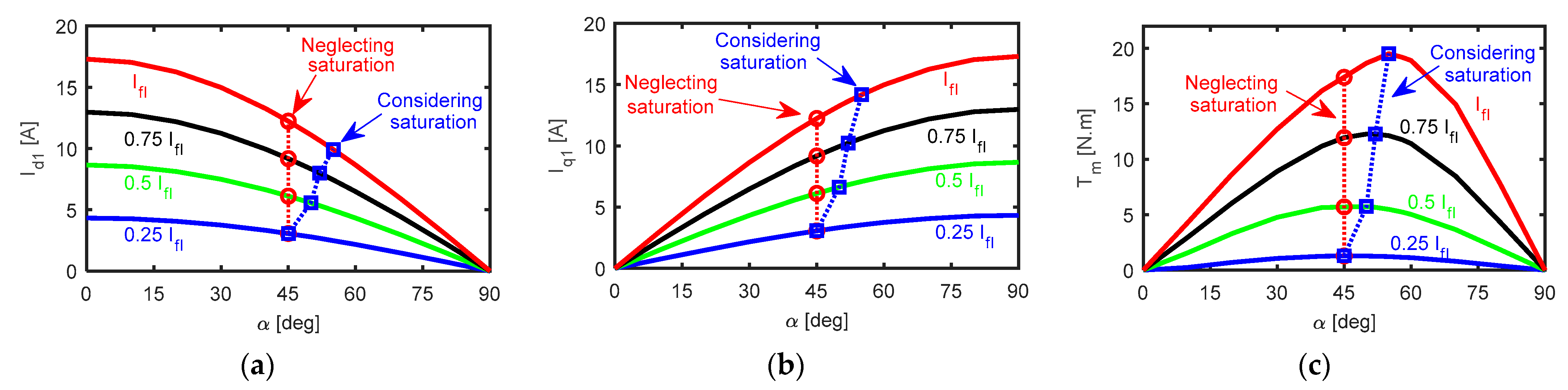
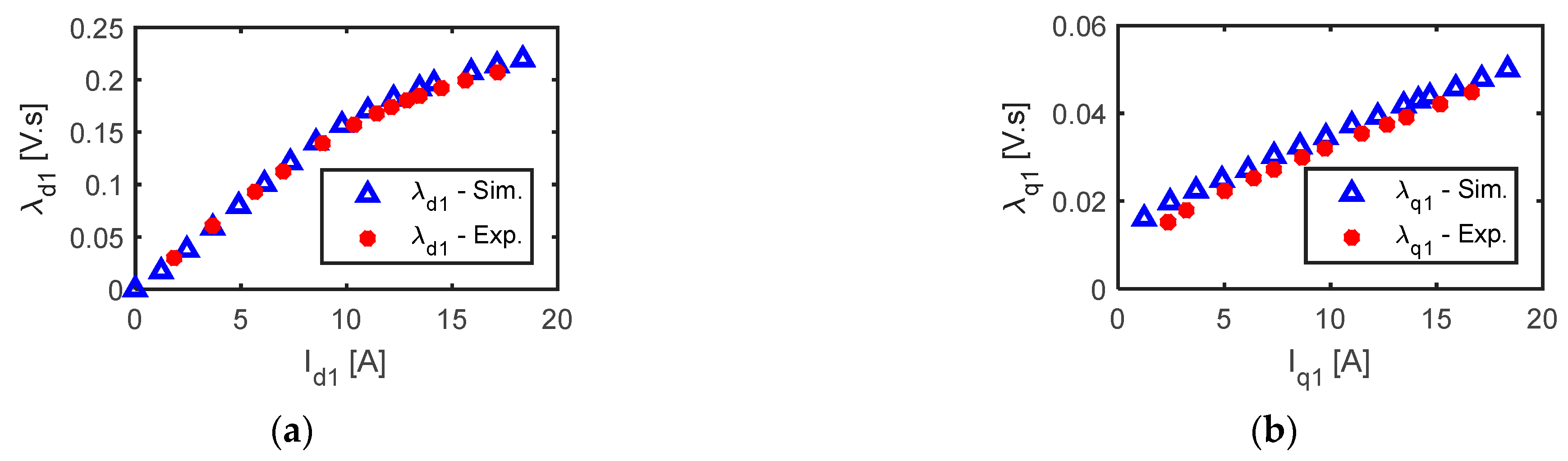
2.1. Effect of Saturation and Cross Saturation on SynRM Flux-Linkages (λd1 and λq1)

This section studies the effect of rotor position and saturation on the fundamental direct and quadrature axis flux-linkage (λd1 and λq1) of a five-phase combined star-pentagon SynRM. The motor is modeled using 2D Ansys Maxwell transient simulations.
Figure 2 shows the average value of the flux-linkage λd1 and λq1 at different id1 and iq1. The flux linkage changes with currents nonlinearly. The effect of saturation on λd1 is noticed (see Figure 2a) and its effect on λq1 can be neglected (see Figure 2b) as the magnetic reluctance in q-axis is high. According to the prior findings, the rotor position and dq-axis currents have a significant impact on the flux-linkage between λd1 and λq1. Therefore, to acquire an accurate performance of the five-phase SynRM, an accurate flux-linkage model is essential.

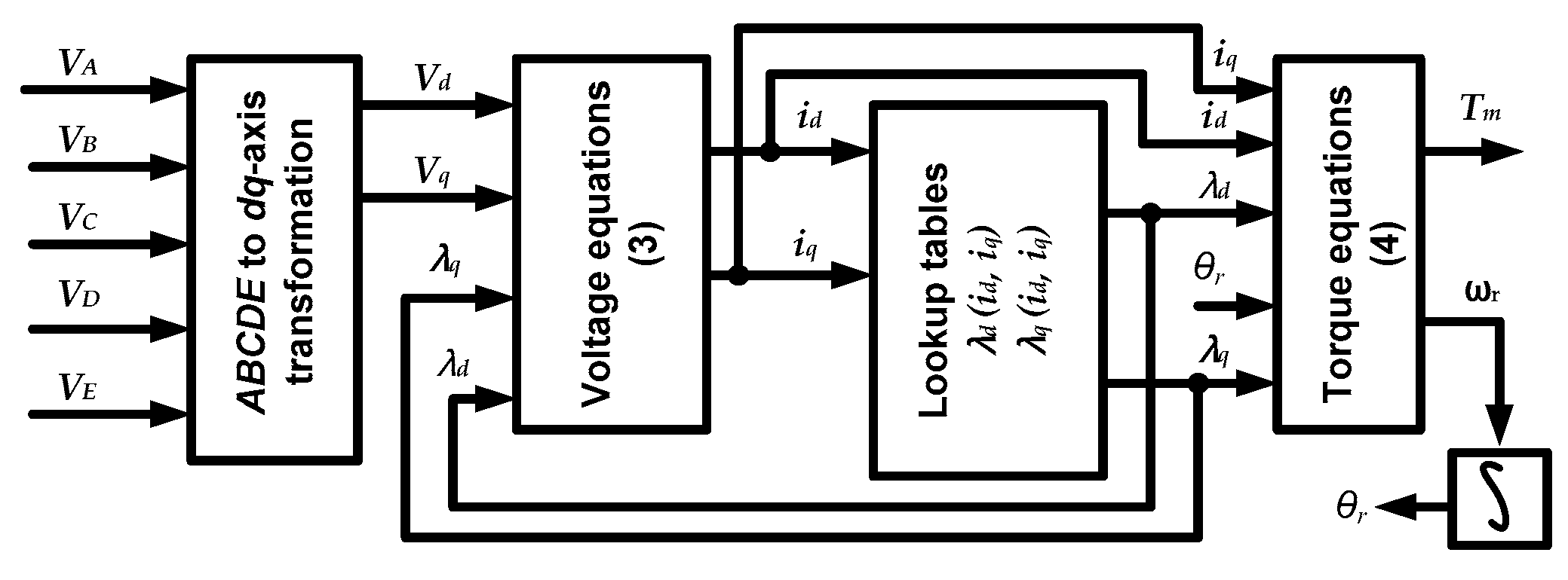
2.2. Modelling Equations of Five-Phase SynRM

The five-phase SynRM fundamental (Vd1 and Vq1), secondary (Vd3 and Vq3), dq-axis voltage equations can be described as follows [22].
{ V d 1 = R p h i d 1 ω r * P * λ q 1 + d λ d 1 d t V q 1 = R p h i q 1 + ω r * P * λ d 1 + d λ q 1 d t       V d 3 = R p h i d 3 3 ω r * P * λ q 3 + d λ d 3 d t V q 3 = R p h i q 3 + 3 ω r * P * λ d 3 + d λ q 3 d t
The five-phase SynRM electromagnetic torque may be expressed mathematically by (4). The factor K c in (4) is dependent on the type of winding. It equals 1 in the star-connected winding and 2 in the combined SP winding. The power factor P F of the SynRM can be expressed by (5) and the torque ripple percentage T r %   can be computed by (6). Figure 3 displays the steady-state vector diagram of the five-phase SynRM.
T m = 5 2 * K c * P * ( λ d ( i d , i q , θ r ) i q λ q ( i d , i q , θ r ) i d )
P F = V d 1 cos ( α ) + V q 1 sin ( α ) V d 1 2 + V q 1 2
T r % = m a x ( T m ) m i n ( T m ) m e a n ( T m ) * 100
There are three models for the fundamental dq-flux-linkage (λd1 and λq1). In the first model (most accurate model), both rotor position and saturation effects are considered. λd1 and λq1 is described by (7).
{ λ d 1 ( i d 1 , i q 1 , θ r ) = L d d ( i d 1 , θ r ) i d + L d q ( i d 1 , i q 1 , θ r ) i q 1 λ q 1 ( i d 1 , i q 1 , θ r ) = L q d ( i d 1 , i q 1 , θ r ) i d + L q q ( i q 1 , θ r ) i q 1
In the second model, the effect of magnetic saturation is only considered. λd1 and λq1 are expressed by:
{ λ d 1 ( i d 1 , i q 1 ) = L d d ( i d 1 ) i d 1 + L d q ( i d 1 , i q 1 ) i q 1 λ q 1 ( i d 1 , i q 1 ) = L q d ( i d 1 , i q 1 ) i d 1 + L q q ( i q 1 ) i q 1
In the third model, the effect of rotor position and magnetic saturation are neglected. λd1 and λq1 are expressed by:
{ λ d 1 = L d i d 1 λ q 1 = L q i q 1
References [23,24,25,26,27,28,29] introduce different methods to obtain the relations of the flux-linkage of SynRM using experimental measurements, numerical calculation, analytical equations, or FEM model. A FEM model was utilized in this study to derive the flux-linkage relations of a five-phase SynRM because it provides a simple and quick accurate model of flux-linkages. Three-dimensional lookup tables for the flux-linkages (λd1 and λq1) were built by solving the FEM model of the five-phase SynRM for different currents (id1 and iq1) and different rotor positions as shown in Figure 4. Based on the given values of id1, iq1, and θr, the flux-linkages described in (7) can be attained directly. The second model, (8) of the five-phase SynRM can be achieved by averaging the lookup tables over θr. Moreover, the third model, (9) can be achieved by selecting constant values of the dq-axis inductances Ld and Lq in the linear region in Figure 2.

3. Five-Phase Indirect Matrix Converter

A matrix converter (MC) converts n-phase quantities to m-phase quantities directly without utilizing any DC link. In this paper, a three to five-phase IMC is considered. The five-phase MC consists of 22 switches as shown in Figure 1b [1,30,31,32]. The required output voltage from five-phase IMC can be obtained by selecting the applicable switching state for MC switches. ISVM technique is the control algorithm that can be utilized in selecting the correct state and its own time period. There are two techniques for SVM. As shown in Figure 1b, this approach treats the five-phase MC as a virtual two-stage converter (controlled rectifier stage and inverter stage) with a virtual DC connection. Then, the duty cycles of three-phase current source rectifier are synchronized with the duty cycles of the five-phase voltage source inverter (five-phase VSI) to attain a zero-current commutation of the rectifier switches, hence minimizing the switching losses.

3.1. Three-Phase Controlled Rectifier Stage

The rectifier stage shown in Figure 1b consists of six switches. Only nine switching states are allowed for these switches to avoid an open circuit on the virtual DC link. These states are six nonzero (active) vectors ( I 1 I 6 ) and three zero vectors ( I 7 I 9 ) as represented in the hexagon in Figure 5a. As shown in (10) and Figure 5a, the reference input current can be obtained using adjacent vectors ( I γ , I δ   and   I 0 ). The duty cycles for both active and zero vectors are calculated as in (11–13) [1,33].
I i n * = d γ I γ + d δ I δ + d o c I 0
  d δ = m i × sin ( π 3 θ i )
  d γ = m i × sin ( θ i )
d 0 c = 1   d γ d δ
where,   m i denotes the modulation index for the input current with range 0:1 and the angle formed between the reference input current vector and the initial vector in the sector where the reference is placed is known as θ i .
The zero-vectors were disregarded during the rectifier-stage modulation in order to obtain the highest DC-link voltage. As a result, the switching sequence is simply made up of the two active-vectors I δ and I γ , whose duty cycles are d x   and   d y , respectively, and may be defined in the first sector as in (14) and (15) respectively.
d x =   d δ   d δ + d γ = v b v a
d y =   d γ   d δ + d γ = v c v a

3.2. Five-Phase Inverter Stage

To avoid short circuits on the virtual DC connection and open circuits at the load terminals, the switches of the inverter stage have 32 permitted switching states. These states are 30 non-zero (active) vectors ( V 1 V 30 ) and two zero vectors (   V 0 ) as displayed in the decagon in Figure 5b. The active vectors are divided into three groups: small vectors (0.2472   V DC ), medium vectors (0.4000   V DC ), and large vectors (0.6472   V DC ) [1,15,30]. As shown in (16) and Figure 5b, the reference output voltage ( V o * ) was obtained using the adjacent vectors ( V α   , V β   and   V z ). These adjacent vectors’ duty cycles were computed as in (17–19). In (17, 18), θ v is the angle formed by the first vector in the sector where the reference is placed and the reference output voltage vector and   m v represents the modulation index of the output voltage [1,15,33]. In the first sector, V α l = 11,001 ,   V α m = 10,000 ,   V β l = 11,000 ,   V β m = 11,101 ,   V z 1 = 00000 and V z 2 = 11,111 .
V O * = d α V α + d β V β + d z V z
d α = m v × sin ( π 5 θ v )
  d β = m v × sin ( θ v )
d z = 1 d α d β
In this paper, medium and large vectors were only considered to attain the reference output voltage so as to minimize the number of switching events. The medium and large vectors’ duty cycles were calculated based on their length to each other as in (20)–(23).
d α l = d α V l V l + V m
d α m = d α V m V l + V m
d β l = d β V l V l + V m
d β m = d β V m V l + V m
Keep in mind that the medium and large vectors’ active periods were 38.2% and 61.8% of the total active time, respectively. The reference output voltage vector’s value was therefore restricted to 0.5257 V D C [34].

3.3. Synchronization between Rectifier and Inverter

The switching pattern must provide an efficient combination of rectifier and inverter switching states in order to achieve balanced input currents and output voltages. The dc-link voltage was varied between two line-to-line input voltages vab and vac when the input current was positioned in sector 1. As a result, the inverter stage’s switching states should be split into two groups, as shown in (24) and Figure 6. The cross product of the duty ratios of the rectifier and inverter stages yields the duty ratio of each space vector in each group. The arrangement shown in Figure 6 ensures zero current commutation for the rectifier switches.
d α l ( x ) = d α l · d x d β l ( x ) = d β l · d x d α m ( x ) = d α m · d x , d β m ( x ) = d β m · d x d z 1 ( x ) = d z 1 · d x d z 2 ( x ) = d z 2 · d x d α l ( y ) = d α l · d y d β l ( y ) = d β l · d y d α m ( y ) = d α m · d y , d β l ( y ) = d β l · d y d z 1 ( y ) = d z 1 · d y d z 2 ( y ) = d z 2 · d y

4. Performance Analysis of the Drive System

In this section, the drive system consists of a three-to-five-phase IMC connected to a five-phase combined star-pentagon SynRM. The closed loop field-oriented control based on a space vector pulse width modulation was applied to control the five-phase SynRM. Figure 7 shows the block diagram of the proposed field-oriented control, implemented to the drive system. The reference signals are the d-axis current (id1*) the motor speed (ωr*).

4.1. Simulation Results

To obtain an improved performance (maximum torque and high efficiency), it is advised to set the five-phase SynRM to operate at its maximum torque per Ampère (MTPA). Figure 8 shows the FEM results of the average torque and dq-axis currents at different line currents, at rated speeds, and at different current angles. The effect of considering and neglecting magnetic saturation on the reference value of d-axis current (id1*) and q-axis current (iq1*) is considered in Figure 8a and Figure 8b respectively.
In Figure 8, the locus of the MTPA in case of considering and neglecting saturation respectively is represented by the blue and red dash-dotted line respectively. It was found that the optimal current angle (gives id1*) varied with line current when considering magnetic saturation while it had a fixed value of 45° when neglecting saturation. When considering magnetic saturation, the average torque in Figure 8c increased by about 9.27% at the rated condition compared with neglecting magnetic saturation. Hence, this paper considered the magnetic saturation in the model and control of the five-phase SynRM.
Different analytical and mathematical approaches were introduced to select id* in [23,26,35] in case of three-phase SynRMs. However, these approaches neglect the effect of cross saturation beside the necessity of obtaining some mathematical constant which may be difficult and complex in some cases. In this paper, as discussed in the previous sections, a FEM model was used to obtain the relation between flux-linkages and currents and between the required torque and the d-axis current. Hence, the reference value of id1* could be obtained as a function of the average torque at the point of MTPA from the one-dimensional lookup table, which is built from the FEM results.
Figure 9 shows the performance of the five-phase SynRM at different load torques and at rated speed. The developed torque of the motor is reported in Figure 9a. In Figure 9a, the reference torque (in red color) represents the required load torque. The fundamental dq-axis currents (id1 and iq1) follow their reference value as shown in Figure 9b,c. The effect of magnetic saturation is considered in determining the value of id1*. It is observed from Figure 9b that the d-axis current varies with the required torque of the load following the MTPA condition. Figure 9d,e shows the zoom-in view of the MC output-phase currents. It is clear from Figure 9d,e that the frequency of currents was 100 Hz. It was noticed that the average torque of the combined star-pentagon SynRM at the rated condition and at the same copper volume was 6.37% higher than the average torque of the star-connected five-phase SynRM, which was introduced in ref. [1].
Figure 10 shows the performance of the combined star-pentagon five-phase SynRM at different speeds and at rated torque. Figure 10a shows that the reference speed decreased from 3000 rpm (rated speed) to 1500 rpm at 1 s then to 750 rpm at 2 s. It was found that the motor speed and the dq-axis currents followed their reference value as shown in Figure 10a–c respectively. The output-phase currents are shown in Figure 10d. From the zoom-in view of the output-phase current shown in Figure 10e,f, it is noticed that the frequency of currents was reduced from100 Hz to 50 Hz at 1 s and then to 25 Hz at 2 s.

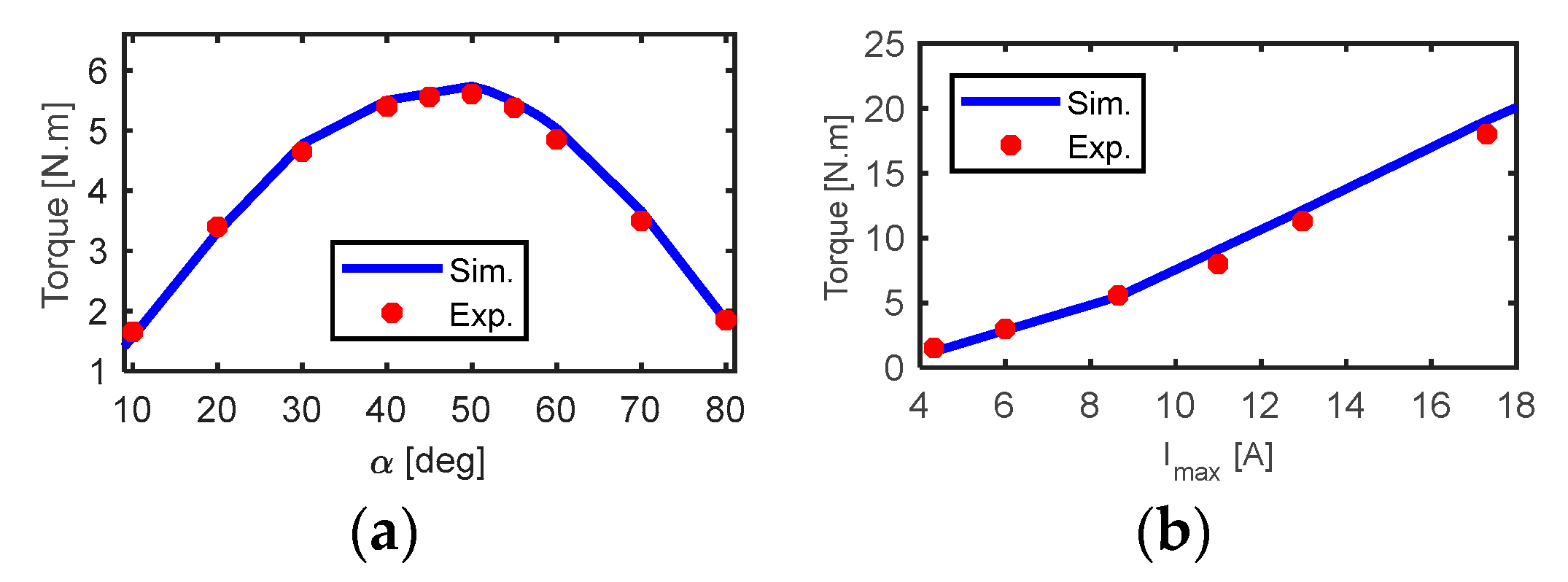
4.2. Experimental Validation of the FEM Model

In the first part of this section, the FEM model of the five-phase combined star-pentagon SynRM was validated. Inductances were measured using the VI method. To simplify the equivalent circuit analysis and provide a sinusoidal MMF, a voltage was injected with an angular frequency ωe in three terminals connected as in Figure 11. The line voltage and current of the motor were measured at standstill as shown in Figure 11 [36].
The first position is at the d-axis where the magnetic reluctance is minimum and the inductance is maximum. This position yields Ld. The second position is at the q-axis where the magnetic reluctance is maximum and the inductance is minimum, giving the value of Lq. These positions are recognized by slow rotation of the rotor of SynRM and observing the measured current and voltage. The maximum ( I max )   and minimum ( I min )   measured currents belong to the q and d-axis positions respectively. In simulation analysis, the connection shown in Figure 11 is used and the mechanical speed of the rotor was set to zero. Then, the d-axis and q-axis positions were adjusted by selecting the initial position of the rotor. The distribution of flux density and flux lines at standstill are shown in Figure 12a,b respectively for pure d-axis and pure q-axis current. From Figure 11, the inductance of the star coil can be obtained as in (25). In (25), I and V are the line current and voltage respectively. In (25), R s is the star coil resistance which is 0.125 ohm and the factor 0.347 depends on the equivalent impedance of the circuit in Figure 11.
Finally, the d-axis and q-axis inductance and flux linkage can be obtained by (26) and (27) respectively. The simulated and measured values of the dq-axis flux linkages ( λ d ( i d , 0 ) and λ q ( 0 , i q ) ) of the five-phase SynRM are shown in Figure 13. There was an acceptable agreement between the measured and simulated results.
L A C = 1 ω e ( 0.347 * V I ) 2 R s 2
L d = L A C m a x   ,   λ d 1 = L d I m i n
L q = L A C m i n , λ q 1 = L q I m a x

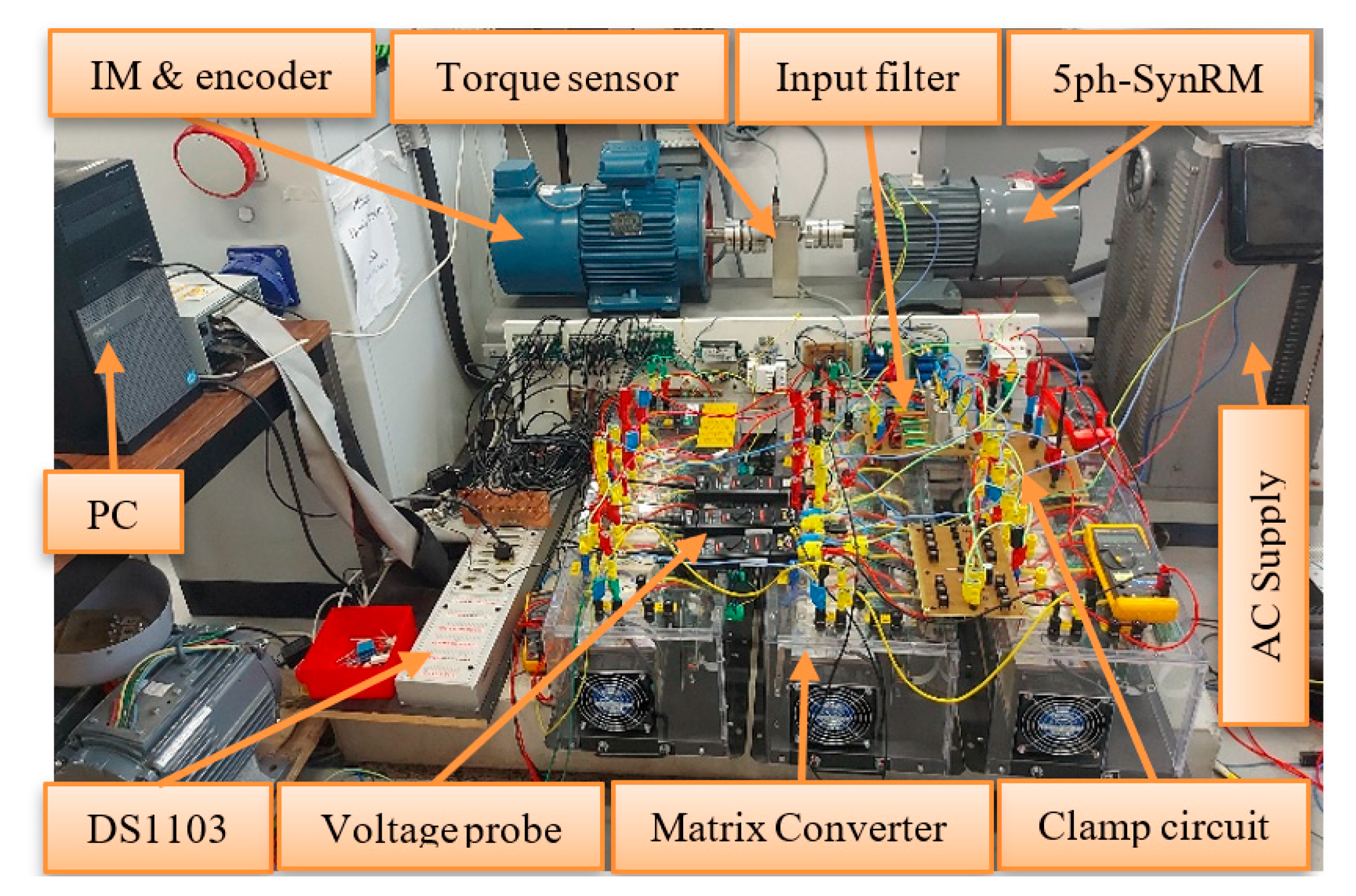
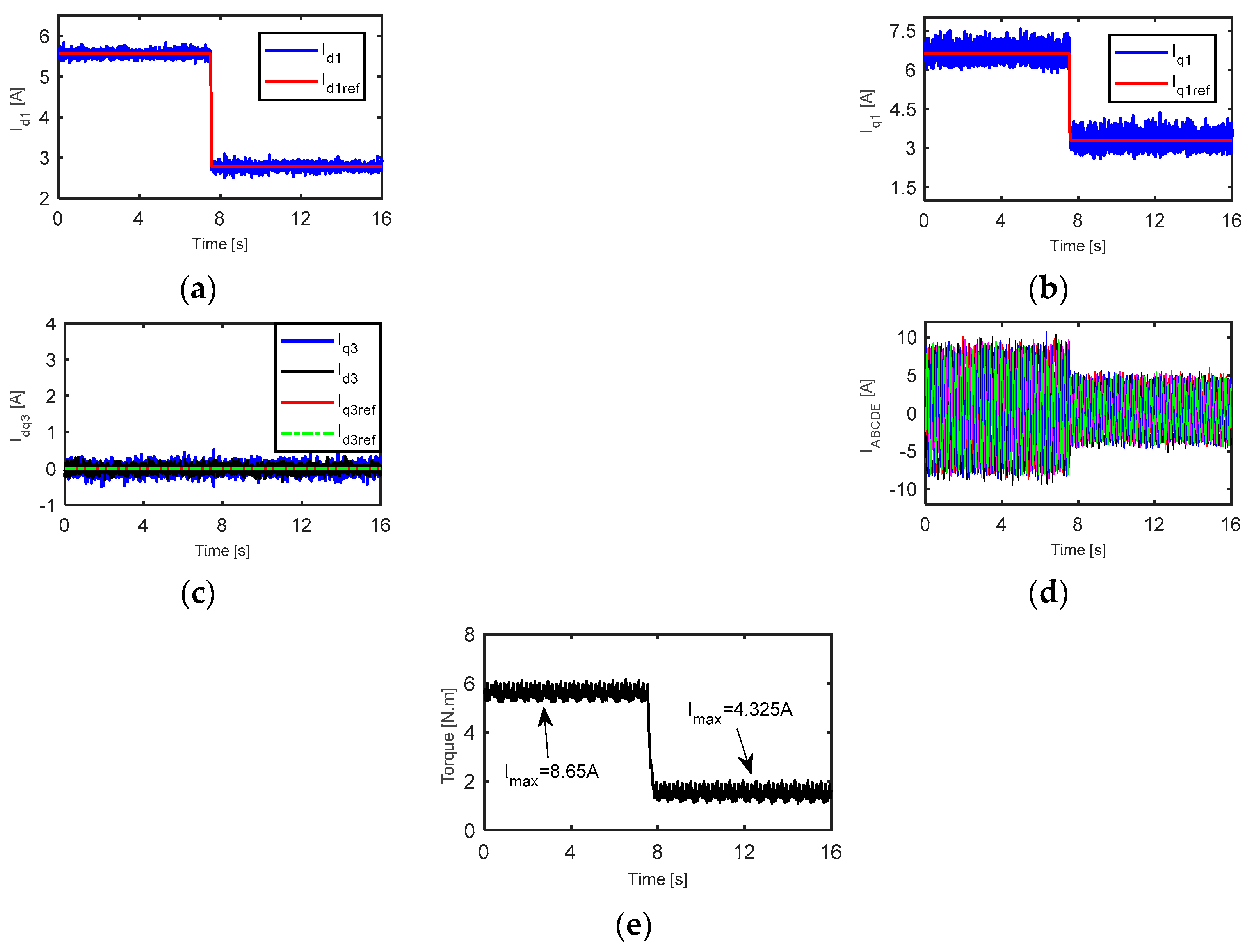
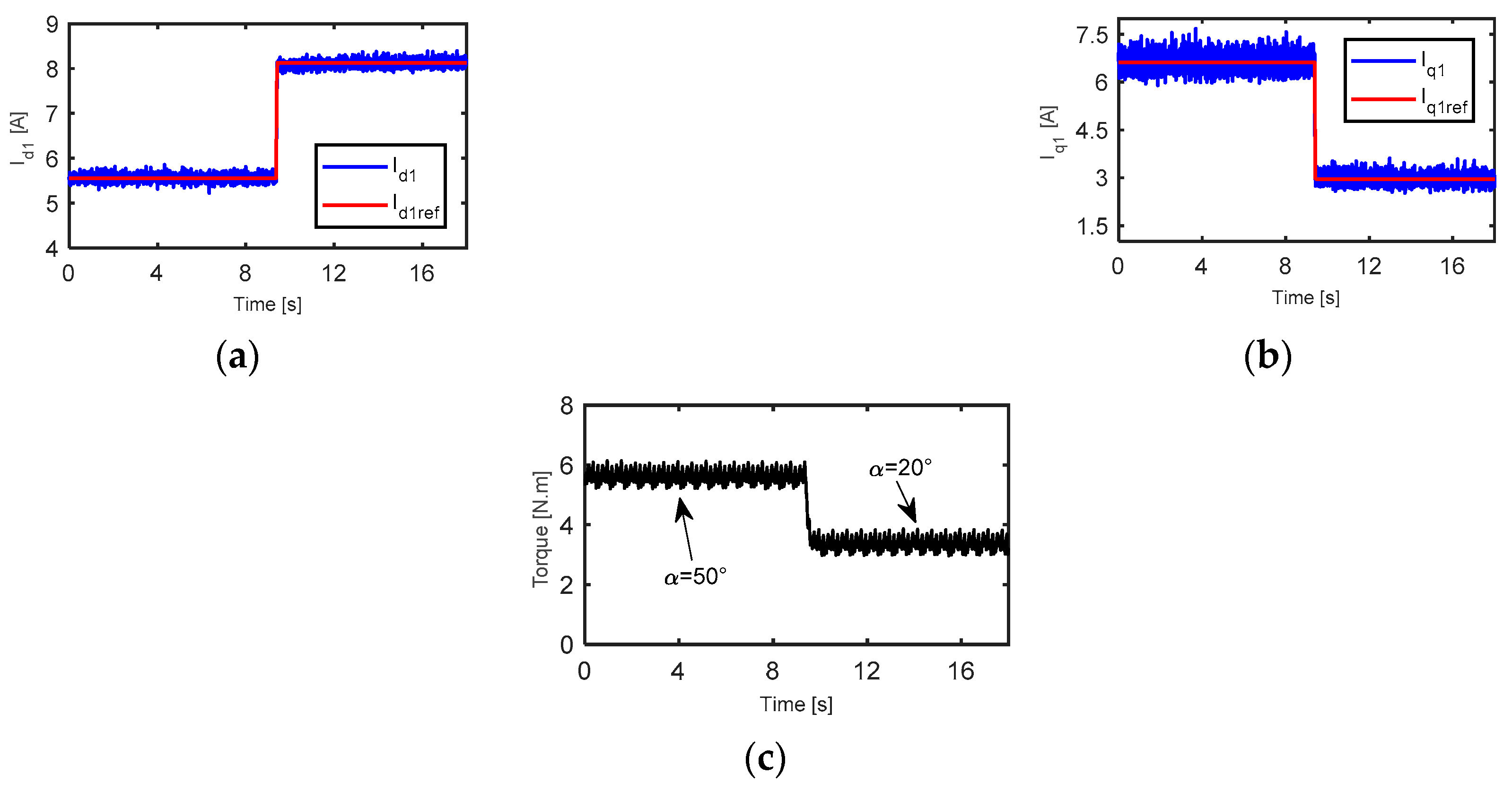
4.3. Experimental Results

A three to five-phase IMC was used to control the five-phase combined star-pentagon SynRM as shown in Figure 14. Indirect SVM was used to control IMC at a switching frequency of 10 kHz. Utilizing an incremental encoder, the operating speed was determined. The filter resistance and inductance were 50 Ω and 3 mH respectively. The clamping capacitor was 110 uF. The five-phase combined star-pentagon SynRM was coupled with the induction machine via torque sensor as shown in Figure 14.
Figure 15a reports the comparison between the simulated and the measured results of the average torque at different current angles and at 8.65 A (half-rated current). The output torque increased as the current angle ( α ) increased until it reached its maximum value at α opt . = 50° which is known as the optimal current angle. If the current angle was still increasing after its optimal value, the torque dropped again after reaching its maximum value. The measured and the simulated torque as a function of line current are compared in Figure 15b. The agreement between the simulated and the measured results was excellent.
The dynamic performance of the drive system under torque control, at the current angle of 50° and with line current changes from 8.65 A to 4.325 A, is reported in Figure 16. The fundamental d-axis and q-axis current (reference values and feedback (fb) values) are described in Figure 16a,b respectively. The third-harmonic dq-axis currents reference and feedback values are shown in Figure 16c. The reference value of fundamental and third harmonics dq-axis currents are followed by the feedback values. The output five-phase currents and torque are described in Figure 16d,e respectively. It is obvious from Figure 16e that the average output torque decreased from 5.7 N m to 1.65 N m when the line current decreased from 8.65 A to 4.325 A respectively.
The dynamic performance of the drive system under torque control, at 8.65 A and with current angle changes from 50° to 20°, is reported in Figure 17. Figure 17a,b show the fundamental d-axis and q-axis currents respectively. Figure 17c shows that the output torque decreased from 5.7 N m to 3.3 N m when the current angle changed from 50° to 20°. The feedback values of the output torque and dq-axis currents follow their reference values. Furthermore, a reasonable agreement between simulation and experimental observations was observed.

5. Analysis of Reliability, Cost, and Performance

This section compares and evaluates the cost, performance, and reliability of the proposed drive system with the conventional drive system. The conventional drive system (Drive-1) consists of a three-phase star-connected SynRM fed from a three-phase conventional rectifier-inverter as shown Figure 1a. The proposed drive system (Drive-2) consists of a rewound combined star-pentagon SynRM fed from a three-to-five-phase indirect MC as shown in Figure 1b.

5.1. Cost Aanalysis of the Drive Systems

In this section, the cost of the two drives is investigated. The number of turns was chosen during the motor design of these drive systems so that the motor can operate at rated power and speed while maintaining the same current across all systems. As a result, the operating voltage of the five-phase drive was 60% of Drive-1’s working voltage. This is obvious from Figure 18. Note that working at the same voltage would be another design choice that could be realized by modifying the numbers of turns.
From the point of view of converter cost, Drive-2 has 16 more switches than Drive-1. However, the switches of Drive-2 have the same current ratings and lower voltage ratings compared with the switches in Drive-1 [37]. Notice that there is a three-phase rectifier bridge and DC-link capacitor in Drive-1, which Drive-2 does not have. Consequently, the overall cost of the power electronic converter in Drive-2 is 36.3% respectively cheaper than Drive-1 [37].
The machine design and construction cost were approximately the same in the two drives. Punching, cutting, iron and copper volume were the same. The only difference between the two machines was that the five-phase drive used a special type of winding which increased winding cost by 20% compared with the three-phase drive. This is based on a questionnaire at a machine manufacturing company. As a result, the machine design cost in Drive-2 was about 4% more expensive compared with Drive-1. For the combined cost of machine and converter, Drive-2 was only 2.19% respectively more expensive than Drive-1 (see Table 2).

5.2. Reliability Analysis of the Drive Systems

This section investigates and studies the reliability of the two drive systems. The power electronic converter is the most fatal component in the drive system. According to a survey based on over 200 products from 80 companies at the same condition, it was found that capacitors and semiconductor failures represent 30% and 21% respectively of all converter failures as shown in Figure 19 [40,41]. Consequently, capacitors are the weakest element in the power electronic converter. Hence, it is recommended to minimize the number of capacitors in the power converter. The others factor of converter failures are PCB, soldering, and connectors. Notice that the two drive systems together have 2 capacitors and 28 semiconductor switches. Drive-1 has two capacitors and six semiconductor switches as shown in Figure 1 and Table 2. Drive-2 has 22 semiconductor switches and there are no capacitors in this drive system as shown in Figure 1 and Table 2.
To determine the percent of fault occurrence in the drive systems, the presented ratios 30%, 21%, and 49% in Figure 19 are considered when a fault occurs in the capacitors, switches, and other parts of one of these power electronic converters. Then, the question is if a fault will happen in one of these drive systems, which drive system has the highest possible probability of fault occurrence ( ε i   % )? The percent of fault occurrence in each drive system was calculated from (28–30). In these equations, the three terms in the summation represent the failure probabilities of the capacitors, the switches, and “other failures” respectively. Drive-1 had the highest percent of fault occurrence, about 59%. Drive-2 had a lower percent of fault occurrence, which was 41%. The absence of capacitors in Drive-2 reduces the chance of a failure occurring in this drive, despite having the highest number of switches. Drive-2 had the better reliability compared with Drive-1.
Furthermore, with one or two phases open, Drive-2 can start and operate, while Drive-1 cannot. This further enhances the reliability of five-phase systems. Moreover, the performance of Drive-2 under the fault case was better than Drive-1. Drive-2 provided 108% higher torque respectively compared with Drive-1 at single-phase open fault. At single-phase open fault, the torque ripple of Drive-2 was 81% lower, respectively, compared with Drive-1.
ε i % =   n u m b e r     o f   e l e m e n t s   i n   d r i v e   n u m b e r   i   t o t a l   n u m b e r   o f   e l e m e n t s   i n   d r i v e s   t o g e t h e r   + 49 n u m b e r   o f   d r i v e   s y s t e m s
ε 1 % = 2 2 * 30 + 6 28 * 21 + 1 2 * 49 = 59 %
ε 2 % = 0 2 * 30 + 22 28 * 21 + 1 2 * 49 = 41 %

5.3. Performance Comparison of the Drive Systems

The detailed study of the performance of the drives is shown in Table 2. Drive-2 provided a 13.35% higher average torque than Drive-1 respectively. The torque ripple of Drive-1 and 2 was 7.94% and 5.52% respectively. Moreover, the power factor of Drive-1 and 2 was 0.6622 and 0.6773 respectively. The efficiency of Drive-2 increased by about 0.58% respectively compared with Drive-1 at rated condition and optimal angle. For Drive-1 and 2, the average torque at the faulty case was reduced by 56.65% and 9.63%, respectively, from the healthy rated value of the Drive-1. At fault case and as shown in Table 2, Drive-3 had the lowest torque ripple of around 43%. The torque ripple of Drive-1 was substantial in the faulty case (228%), resulting in increased noise, vibrations, and mechanical issues. Hence, Drive-2 provided a significantly improved performance compared with the three-phase drive system (Drive-1).

6. Conclusions

This paper presented a reliable and improved performance drive topology, i.e., combined star-pentagon SynRM driven by three-to-five-phase IMC. The topology avoids single points of failure of conventional drives by using MC without vulnerable electrolytic capacitors. A simple and accurate model of the five-phase combined star-pentagon SynRM was proposed considering the effect of magnetic saturation and cross saturation on dq-flux-linkages. A FEM model was utilized to obtain the dq-flux-linkages relations of the five-phase SynRM. Three-dimensional lookup tables for the flux-linkages (λd1 and λq1) were built by solving the FEM model of the five-phase SynRM for different currents (id1 and iq1) and different rotor positions. An experimental validation for the FEM model of the five-phase SynRM was introduced.
Then, the indirect field-oriented control based on a space vector pulse width modulation of the proposed drive system was proposed and validated. The rectifier switches were commutated at zero current.
The proposed drive system was compared with the conventional three-phase drive system in term of cost, reliability, and performance. The proposed drive was just 2.19% more expensive than Drive-1 in terms of overall initial cost (machine and converter cost). At rated condition and at optimal current angle, Drive-2 was determined to have 13.35% greater average torque than Drive-1, respectively. The torque ripple of Drive-1 and 2 was 7.94% and 5.52% respectively.
Furthermore, Drive-2 was more reliable compared with Drive-1. The probability of a fault occurring in Drives-2 was 30.5% lower compared with Drive-1.

Author Contributions

Conceptualization, K.B.T.; methodology, K.B.T.; software, K.B.T.; validation, K.B.T.; investigation, K.B.T.; writing—original draft preparation, K.B.T.; writing—review and editing, M.N.I. and P.S.; visualization, M.N.I. and P.S.; supervision, M.N.I. and P.S. All authors have read and agreed to the published version of the manuscript.

Funding

The authors acknowledge the Special Research Fund of Ghent University, Belgium (BOF).

Data Availability Statement

The study did not report any data.

Conflicts of Interest

The authors declare no conflict of interest.

References

  1. Tian, B.; Molinas, M.; An, Q.; Zhou, B.; Wei, J. Freewheeling Current-Based Sensorless Field-Oriented Control of Five-Phase Permanent Magnet Synchronous Motors under Insulated Gate Bipolar Transistor Failures of a Single Phase. IEEE Trans. Ind. Electron. 2022, 69, 213–224. [Google Scholar] [CrossRef]
  2. Sadeghi, S.; Parsa, L. Multiobjective Design Optimization of Five-Phase Permanent-Magnet Machine. IEEE Trans. Magn. 2011, 47, 1658–1666. [Google Scholar] [CrossRef]
  3. Wang, B.; Wang, J.; Sen, B.; Griffo, A.; Sun, Z.; Chong, E. A Fault-Tolerant Machine Drive Based on Permanent Magnet-Assisted Synchronous Reluctance Machine. IEEE Trans. Ind. Appl. 2018, 54, 1349–1359. [Google Scholar] [CrossRef]
  4. Ward, E.E.; Harer, H. Preliminary investigation of an inverter-fed 5-phase induction motor. Electr. Eng. Proc. Inst. 1969, 116, 980–984. [Google Scholar] [CrossRef]
  5. Levi, E. Advances in converter control and innovative exploitation of additional degrees of freedom for multiphase machines. IEEE Trans. Ind. Electron. 2016, 63, 433–448. [Google Scholar] [CrossRef]
  6. Toliyat, H.A.; Xu, L.; Lipo, T.A. A Five Phase Reluctance Motor with High Specific Torque. IEEE Trans. Ind. Appl. 1992, 28, 659–667. [Google Scholar] [CrossRef]
  7. Williamson, S.; Smith, S. Pulsating torques and losses in multiphase induction machines. IEEE Trans. Ind. Appl. 2003, 39, 986–993. [Google Scholar] [CrossRef]
  8. Hu, J.S.; Chen, K.Y.; Shen, T.Y.; Tang, C.H. Analytical solutions of multilevel space-vector PWM for multiphase voltage source inverters. IEEE Trans. Power Electron. 2011, 26, 1489–1502. [Google Scholar] [CrossRef]
  9. Amin, A.; Tawfiq, K.B.; Youssef, H.; El-Kholy, E.E. Performance analysis of inverter fed from wind energy system. In Proceedings of the 2016 Eighteenth International Middle East Power Systems Conference (MEPCON), Cairo, Egypt, 27–29 December 2016; pp. 512–516. [Google Scholar]
  10. Scuiller, F.; Charpentier, J.; Semail, E. Multi-star multi-phase winding for a high-power naval propulsion machine with low ripple torques and high fault tolerant ability. In Proceedings of the IEEE Vehicle Power and Propulsion Conference (VPPC’10), Lille, France, 1–3 September 2010; pp. 26–29. [Google Scholar]
  11. Iqbal, A.; Ahmed, S.M.; Abu-Rub, H. Space Vector PWM Technique for a Three-to-Five-Phase Matrix Converter. IEEE Trans. Ind. Appl. 2012, 48, 697–707. [Google Scholar] [CrossRef]
  12. Kavitha, P.; umamaheswari, B. Bus synchronized matrix converter fed switched reluctance machine in motoring and generating modes of operation. Int. J. Soft Comput. 2014, 9, 391–400. [Google Scholar]
  13. Tawfiq, K.B. Performance Improvement of Existing Three Phase Synchronous Reluctance Machine: Stator Upgrading to 5-Phase with Combined Star-Pentagon Winding. IEEE Access 2020, 8, 143569–143583. [Google Scholar] [CrossRef]
  14. Park, J.-K.; Babetto, C.; Berardi, G.; Hur, J.; Bianchi, N. Comparison of Fault Characteristics According to Winding Configurations for Dual Three-Phase Synchronous Reluctance Motor. IEEE Trans. Ind. Appl. 2021, 57, 2398–2406. [Google Scholar] [CrossRef]
  15. Cupertino, F.; Pellegrino, G.; Gerada, C. Design of Synchronous Reluctance Motors with Multiobjective Optimization Algorithms. IEEE Trans. Ind. Appl. 2014, 50, 3617–3627. [Google Scholar] [CrossRef]
  16. Credo, A.; Villani, M.; Popescu, M.; Riviere, N. Application of Epoxy Resin in Synchronous Reluctance Motors with Fluid-Shaped Barriers for E-Mobility. IEEE Trans. Ind. Appl. 2021, 57, 6440–6452. [Google Scholar] [CrossRef]
  17. Abdel-Khalik, A.S.; Elgenedy, M.A.; Ahmed, S.; Massoud, A.M. An Improved Fault-Tolerant Five-Phase Induction Machine Using a Combined Star/Pentagon Single Layer Stator Winding Connection. IEEE Trans. Ind. Electron. 2016, 63, 618–628. [Google Scholar] [CrossRef]
  18. Tawfiq, K.B.; Ibrahim, M.N.; EL-Kholy, E.E.; Sergeant, P. Construction of Synchronous Reluctance Machines with Combined Star-Pentagon Configuration Using Standard Three-Phase Stator Frames. IEEE Trans. Ind. Electron. 2022, 69, 7582–7595. [Google Scholar] [CrossRef]
  19. Raziee, S.M.; Misir, O.; Ponick, B. Multiple Multiphase Combined Star–Polygon Winding Analysis. IEEE Trans. Ind. Electron. 2019, 66, 7468–7479. [Google Scholar] [CrossRef]
  20. Mohammadpour, A.; Sadeghi, S.; Parsa, L. A Generalized Fault-Tolerant Control Strategy for Five-Phase PM Motor Drives Considering Star, Pentagon, and Pentacle Connections of Stator Windings. IEEE Trans. Ind. Electron. 2014, 61, 63–75. [Google Scholar] [CrossRef]
  21. Abdel-Khalik, A.S.; Ahmed, S.; Massoud, A.M. Dynamic Modeling of a Five-Phase Induction Machine with a Combined Star/Pentagon Stator Winding Connection. IEEE Trans. Energy Convers. 2016, 31, 1645–1656. [Google Scholar] [CrossRef]
  22. Tawfiq, K.B.; Ibrahim, M.N.; El-Kholy, E.E.; Sergeant, P. Refurbishing three-phase synchronous reluctance machines to multiphase machines. Electr. Eng. 2020, 103, 139–152. [Google Scholar] [CrossRef]
  23. Yamamoto, S.; Ara, T.; Matsuse, K. A Method to Calculate Transient Characteristics of Synchronous Reluctance Motors Considering Iron Loss and Cross-Magnetic Saturation. IEEE Trans. Ind. Appl. 2007, 43, 47–56. [Google Scholar] [CrossRef]
  24. Ferrari, M.; Bianchi, N.; Fornasiero, E. Analysis of Rotor Saturation in Synchronous Reluctance and PM-Assisted Reluctance Motors. IEEE Trans. Ind. Appl. 2015, 51, 169–177. [Google Scholar] [CrossRef]
  25. Levi, E. Saturation modelling in d-q axis models of salient pole synchronous machines. Trans. Energy Convers. 1999, 14, 44–50. [Google Scholar] [CrossRef]
  26. Lubin, T.; Razik, H.; Rezzoug, A. Magnetic saturation effects on the control of a synchronous reluctance machine. IEEE Trans. Energy Convers. 2002, 17, 356–362. [Google Scholar] [CrossRef]
  27. Vagati, A.; Pastorelli, M.; Scapino, F.; Franceschini, G. Impact of cross saturation in synchronous reluctance motors of the transverse-laminated type. IEEE Trans. Ind. Electron. 2000, 36, 1039–1046. [Google Scholar] [CrossRef]
  28. Quéval, L.; Ohsaki, H. Nonlinear abc-Model for Electrical Machines Using N-D Lookup Tables. IEEE Trans. Energy Convers. 2015, 30, 316–322. [Google Scholar] [CrossRef]
  29. Tawfiq, K.B.; Ibrahim, M.N.; Sergeant, P. An Enhanced Fault-Tolerant Control of a Five-Phase Synchronous Reluctance Motor Fed from a Three-to-Five-Phase Matrix Converter. IEEE J. Emerg. Sel. Top. Power Electron. 2022, 10, 4182–4194. [Google Scholar] [CrossRef]
  30. Tawfiq, K.B.; Ibrahim, M.N.; Sergeant, P. Power Loss Analysis of a Five-Phase Drive System Using a Synchronous Reluctance Motor and an Indirect Matrix Converter with Reduced Switching Losses. Machines 2022, 10, 738. [Google Scholar] [CrossRef]
  31. Tawfiq, K.B.; Ibrahim, M.N.; Rezk, H.; El-Kholy, E.E.; Sergeant, P. Mathematical Modelling, Analysis and Control of a Three to Five-Phase Matrix Converter for Minimal Switching Losses. Mathematics 2021, 9, 96. [Google Scholar] [CrossRef]
  32. Wang, H.; Zhang, Y.; Su, M.; Sun, Y.; Li, X.; Zhang, G. Control method for the two-stage matrix converter to enhance the linear voltage transfer ratio. IET Power Electron. 2018, 11, 2295–2301. [Google Scholar] [CrossRef]
  33. Ramalho, A.; Vitorino, M.A.; Correa, M.; Costa, L.A.C.; Braga-Filho, E. New Family of Two-to-Three-Phase AC-AC Indirect Matrix Converters with Open-end Rectifier Stage. IEEE Trans. Ind. Appl. 2021, 58, 517–530. [Google Scholar] [CrossRef]
  34. Dabour, S.M.; Hassan, A.E.; Rashad, E. Analysis and implementation of space vector modulated five-phase matrix converter. Int. J. Electron. Power Energy Syst. 2014, 63, 740–746. [Google Scholar] [CrossRef]
  35. Rashad, E.M.; Radwan, T.S.; Rahman, M.A. A maximum torque per ampere vector control strategy for synchronous reluctance motors considering saturation and iron losses. In Proceedings of the 39th IAS Annual Meeting Conference Record of the 2004 IEEE Industry Applications Conference, Seattle, WA, USA, 3–7 October 2004; Volume 4, pp. 2411–2417. [Google Scholar]
  36. Hwang, S.-H.; Kom, J.-M.; Khang, H.V.; Ahn, J.-W. Parameter identification of a synchronous reluctance motor by using asynchronous PI current regulator at a standstill. J. Power Electron. 2010, 10, 491–497. [Google Scholar] [CrossRef]
  37. Available online: https://be.farnell.com/ (accessed on 1 April 2021).
  38. Domingues-Olavarría, G.; Márquez-Fernández, F.J.; Fyhr, P.; Reinap, A.; Andersson, M.; Alaküla, M. Optimization of Electric Powertrains Based on Scalable Cost and Performance Models. IEEE Trans. Ind. Appl. 2019, 55, 751–764. [Google Scholar] [CrossRef]
  39. Bonthu, S.S.R.; Choi, S.; Baek, J. Comparisons of three-phase and five-phase permanent magnet assisted synchronous reluctance motors. IET Electron. Power Appl. 2016, 10, 347–355. [Google Scholar] [CrossRef]
  40. Yang, S.; Xiang, D.; Bryant, A.; Mawby, P.; Ran, L.; Tavner, P. Condition Monitoring for Device Reliability in Power Electronic Converters: A Review. IEEE Trans. Power Electron. 2010, 25, 2734–2752. [Google Scholar] [CrossRef]
  41. Wolfgang, E. Examples for Failures in Power Electronics Systems; ECPE Tutorial on Reliability of Power Electronic Systems: Nuremberg, Germany, 2007. [Google Scholar]
Figure 1. (a) The conventional drive system, (b) the proposed drive system.
Mathematics 10 03351 g001
Figure 2. Average value of (a) fundamental d-axis flux-linkage and (b) fundamental q-axis flux-linkage at different id1 and iq1.
Mathematics 10 03351 g002
Figure 3. SynRM vector diagram in steady state.
Mathematics 10 03351 g003
Figure 4. Five-phase SynRM block diagram with look-up tables.
Mathematics 10 03351 g004
Figure 5. (a) Hexagon of the controlled rectifier and (b) decagon of the five-phase inverter.
Mathematics 10 03351 g005
Figure 6. Switching outline of the five-phase IMC in half of the sample duration.
Mathematics 10 03351 g006
Figure 7. Block diagram of five-phase SynRM with MC under field-oriented control.
Mathematics 10 03351 g007
Figure 8. Five-phase combined star-pentagon SynRM; (a) fundamental d-axis current, (b) fundamental q-axis current, and (c) average torque at different currents, at different current angle and at rated speed.
Mathematics 10 03351 g008
Figure 9. Simulated performance of the five-phase combined star-pentagon SynRM at rated speed and different loads, (a) average torque, (b) d-axis current, (c) q-axis current, and (d,e) zoom-in view of five-phase currents.
Mathematics 10 03351 g009
Figure 10. Simulated performance of the five-phase combined star-pentagon SynRM at rated torque and different speeds, (a) SynRM speed, (b) d-axis current, (c) q-axis current, (d) five-phase currents, and (e,f) zoom-in view of five-phase currents.
Mathematics 10 03351 g010
Figure 11. Measuring the inductances using the VI method.
Mathematics 10 03351 g011
Figure 12. Distribution of flux density and flux lines at standstill and at the peak of the rated current at (a) position of the minimum reluctance (d-axis) and (b) position of the maximum reluctance (q-axis).
Mathematics 10 03351 g012
Figure 13. Simulated and measured (a)   λ d 1 ( i d 1 , 0 ) and (b)   λ q 1 ( 0 , i q 1 ) at different currents and at standstill.
Mathematics 10 03351 g013
Figure 14. The complete experimental test bench.
Mathematics 10 03351 g014
Figure 15. Measured and simulated average torque at (a) different current angles and 8.65 A and (b) different line currents and optimal current angles.
Mathematics 10 03351 g015
Figure 16. Dynamic performance of drive system at current angle of 50° and current changes from 8.65 A to 4.325 A; (a) fundamental d-axis current, (b) fundamental q-axis current, (c) third-harmonics dq-axis currents, (d) five-phase currents, and (e) the time response of the output torque.
Mathematics 10 03351 g016
Figure 17. Dynamic performance of drive system at 8.65 A with current angle changes from 50° to 20°; (a) fundamental d-axis current, (b) fundamental q-axis current, and (c) the time response of the output torque.
Mathematics 10 03351 g017
Figure 18. Induced EMF at optimal current angle and rated condition.
Mathematics 10 03351 g018
Figure 19. Distribution of failures between components of power electronic converters [40,41].
Mathematics 10 03351 g019
Table 1. The five-phase SynRM geometrical parameters.
ParameterValueParameterValue
Stator bore diameter (D1O)110 mmAir gap length (Lg)0.3 mm
Stator inner diameter (D)180 mmNumber of slots (S)36
Rotor outer diameter (Dro)109.4 mmPole pairs (P)2
Rotor inner diameter (Dri)35 mmRated frequency (F)100 Hz
Axial length (L)140 mmRated power (Pr)5.5 kW
Number of turns of star coil per phase24Number of turns of pentagon coil per phase29
Stator/Rotor steelM270-50A/M330-50ARated current (Is)12.3 A
Rotor flux barriers per pole (Nfb)3Number of phases (m)5
Phase   resistance   ( R p h )0.25 Star   coil   resistance   ( R s )0.125
Table 2. Performance, cost, and reliability comparison of the two drive systems [37,38,39].
ParametersDrive-1Drive-2
CostCopper cost (pu)11.029
Winding cost (pu)11.2
Punching, cutting and iron cost (pu)11
Machine cost (pu)11.04
Diode bridge cost (pu)10
Number of switches622
Switches I- rating (pu)11
Switches V- rating (pu)10.6
Switches cost (pu)11.941
DC-link capacitor cost (pu)10
Converter cost (pu)10.637
Total initial cost (pu)11.0219
PerformanceMMF Magnitude (pu)11.0729
MMF THD (pu)10.8010
Winding factor (pu)11.0321
Average torque (pu)11.1335
Torque ripple (pu)10.6952
Power factor11.0228
Power flow directionUni.Bi.
Efficiency (pu)11.0058
ReliabilityAverage torque at one phase open (pu)12.08
Torque ripple at one phase open (pu)10.189
Starting with one/two phase openNoYes
Probability   of   fault   occurrence   ( ε i   % )59%41%
Reliability++++
Publisher’s Note: MDPI stays neutral with regard to jurisdictional claims in published maps and institutional affiliations.

