Abstract
The development of different industrial fields, including mechanical and power engineering and electronics, demands the augmentation of heat transfer in engineering devices. Such enhancement can be achieved by adding extended heat transfer surfaces to the heated walls or heat-generating elements. This investigation is devoted to the numerical analysis of natural convective energy transport in a differentially heated chamber with isothermal vertical walls and a fin system mounted on the heated wall. The developed in-house computational code has been comprehensively validated. The Forchheimer–Brinkman extended Darcy model has been employed for the numerical simulation of transport phenomena in a porous material. The partial differential equations written, employing non-primitive variables, have been worked out by the finite difference technique. Analysis has been performed for solid and porous fins with various fin materials, amounts and heights. It has been revealed that porous fins provide a very good technique for the intensification of energy removal from heated surfaces.
1. Introduction
Energy transport enhancement can be achieved using different passive techniques, including modern heat transfer liquids (non-Newtonian fluids, nanofluids) or extended heat transfer surfaces [1,2,3]. It should be noted that passive energy transport enhancement techniques are more attractive for engineers and scientists due to low financial expense, low noise and the natural conditions involved in such a system. Nowadays, there are several published papers on the application of extended heat transfer surfaces in engineering devices, including modes of natural, forced or mixed convection [4,5,6,7,8,9,10,11,12,13,14,15].
In the case of forced and mixed convective energy transport, solid and porous fins are widely used in different channels and tubes [4,5,6,7,8,9,10]. Thus, Gong et al. [4] have calculated convective energy transport in a channel with solid and metallic porous fins on the basis of the boundary-value problem for the partial differential equations. Numerical analysis has been conducted by employing the primitive variables and finite volume technique. Authors have revealed that porous fins for the considered problem are not effective due to their low effective thermal conductivity. Kumar and Jayavel [5] have numerically analyzed the influence of porous fins in a rectangular microchannel on heat transference augmentation compared to solid fins. Using primitive variables combined with Navier–Stokes equations for the viscous fluid and the Forchheimer–Brinkman extended Darcy approach for the porous fins, the developed equations have been solved by using commercial CFD software. Obtained outcomes have demonstrated that the introduction of porous fins allows for a reduction in the channel pressure drop. High fin porosity characterizes a low energy transport rate, while an increase in the porous fin permeability diminishes the average heat transfer coefficient. Computational analysis of an air-turbulent convective heat transport in a system with porous pin fin heat sinks has been performed by Ranjbar et al. [6], using commercial CFD software. The authors revealed that the arrangement and permeability of pin fins have a huge influence on energy transport effectiveness. Vatanparast et al. [7] have scrutinized numerically forced convection in a partially heated horizontal channel with staggered semi-porous fins. Using the primitive variables and finite volume technique, the authors have analyzed the impact of the Reynolds and Darcy numbers, as well as fin sizes and the thermal conductivity ratio on flow structures, entropy generation and the heat transfer regime. It has been ascertained that entropy generation can be increased with the effective fins’ thermal conductivity. Kansara et al. [8] have investigated computationally and experimentally forced convection in a channel mounted with fins or porous metal foam for the effectiveness of flat-plate solar collection. Computational research has been conducted employing commercial CFD software, while experiments have been conducted for two collectors, namely, an empty channel and finned channel. Authors have shown that the addition of porous material allows for intensification of the energy transport compared to empty and finned collectors. An analysis of the influence of pin fins on flow and energy transport parameters between two- and three-layer porous laminates has been performed experimentally and numerically using commercial software by Zhang et al. [9]. Authors have found that the shape of the pin fins has an essential influence on system effectiveness. Yerramalle et al. [10] have calculated the mixed convection in a horizontal channel with a porous fin over a heated part of the bottom wall. Analysis of the transport processes in a porous material has been performed employing the local thermal non-equilibrium model. Using commercial software, it has been demonstrated that a rise in the porosity, effective thermal conductivity and Reynolds number results in more essential heat removal from the heater.
According to the above literature review, fin shape, arrangement and material have a significant influence on heat transfer performance in various channels. It is interesting to note that in the case of forced or mixed convection in channels, porous fins can be effective [9,10], or not [4,5]. At the same time, researchers have mainly relied on commercial software for numerical analysis of the solid/porous fins’ efficacy.
In the case of the natural convection phenomenon analysis of solid/porous fins’ influence on energy transport, performance is not so widespread [11,12,13,14,15]. Thus, Alshuraiaan and Khanafer [11] have examined the influence of a single porous fin mounted on the left vertical heated wall or the bottom horizontal adiabatic wall. Analysis has been conducted numerically using Navier–Stokes equations for clear parts and the Forchheimer–Brinkman extended Darcy model for porous fins with the local thermal equilibrium approach. Using a finite element technique, the authors have found that the use of horizontal porous fins mounted on the vertical heated wall is more effective, and an average Nusselt number depends on the effective thermal conductivity. Martin et al. [12] have analyzed the numerically natural convection of copper/water nanosuspension in a porous medium under the influence of solid fins. Using primitive variables and a finite volume algorithm, the authors have ascertained that porous material saturated with nanosuspension allows for an improvement of the cooling effect. Keramat et al. [13] have scrutinized free convection in a differentially heated enclosure with a solid base and porous fins using commercial software. The Forchheimer–Brinkman extended Darcy approach has been employed for porous fins. The authors have found that a high energy transport rate is achieved for the porous finned cavity at high Rayleigh numbers, while solid fins degrade the energy transport efficacy. Asl et al. [14] have numerically studied the impact of solid and porous fins on heat transfer performance in an inclined, tall cavity. Using primitive variables and the Brinkman-extended Darcy approach for the porous fins, governing equations have been formulated and solved by the finite volume method. It has been concluded that porous fins are more effective, and an increase in the Darcy number augments the energy transport. Some interesting and useful data can also be found in [15,16,17,18].
The above review of an application of solid/porous fins in closed chambers with heated surfaces illustrates the efficacy of porous fins. Unfortunately, there is little information about the influence of a porous fin located at the heated wall, or the length of this fin on energy transference enhancement. Moreover, analysis is often performed using commercial software and sometimes in-house computational codes with primitive variables. Therefore, the aim of the present research is a computational analysis of energy transfer performance in a differentially heated chamber with solid and porous horizontal fins, taking into account the fins’ number, length, location and material. Analysis has been conducted on the basis of a developed in-house computational technique using non-primitive variables.
2. Mathematical Modeling
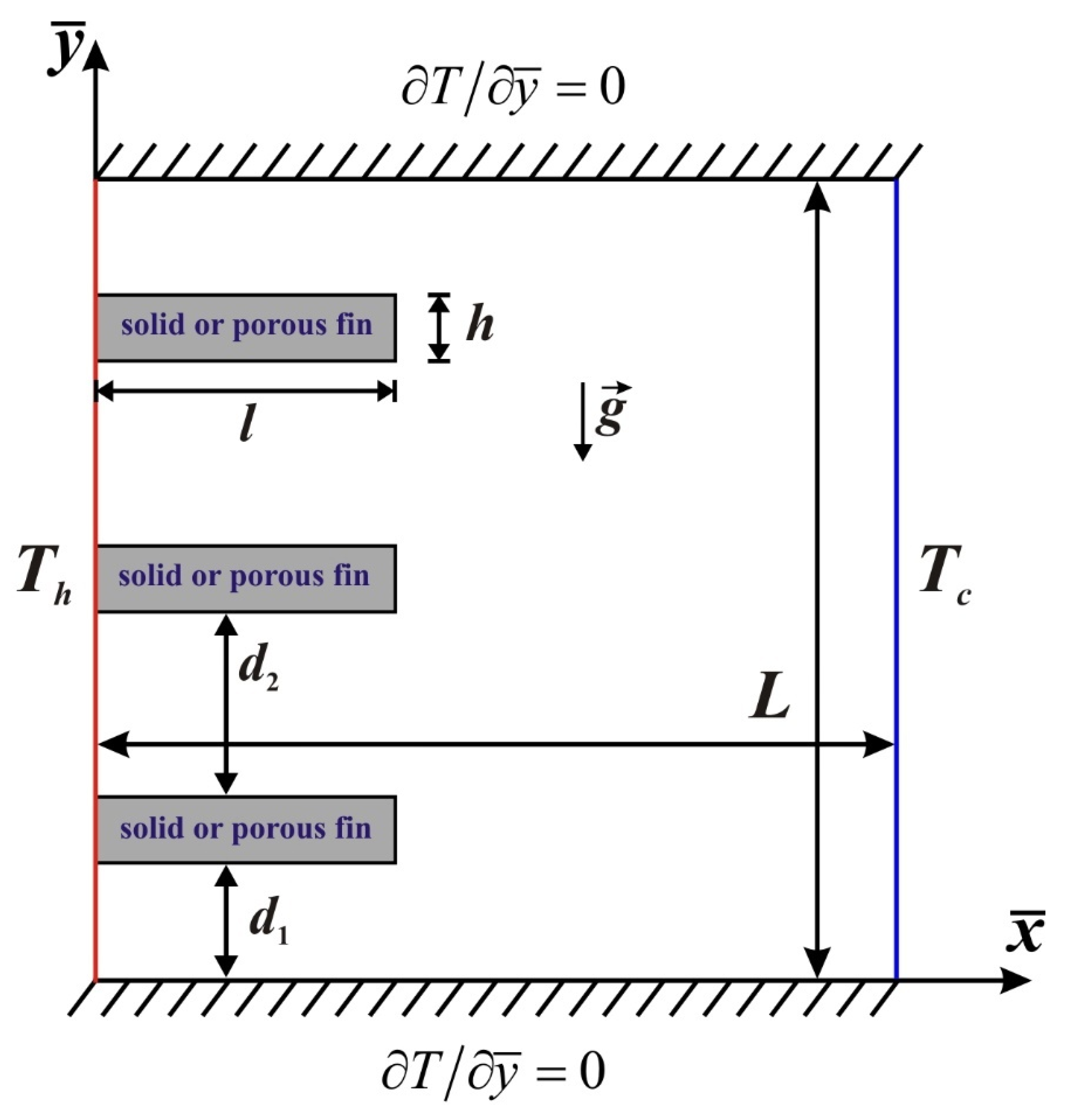
The investigation of free convection of a viscous fluid in a square differentially heated chamber with solid or porous fins mounted on the heated vertical wall has been performed numerically. The considered vertically oriented system is presented in Figure 1, where air (Pr = 0.71) is circulated within the chamber. Here, and are the dimensional Cartesian coordinates, while the left vertical border is heated and the right one is cooled to maintain constant temperatures Th and Tc, respectively. The density variation is described by the Boussinesq approximation [19,20]. Moreover, the temperature of the porous solid matrix is equal to the liquid temperature, and as a result, the local thermal equilibrium model is applied. The transport phenomena within the porous material are simulated using the Forchheimer–Brinkman extended Darcy model. It is assumed that viscous dissipation and pressure work are negligible.
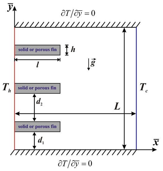
Figure 1.
Coordinate system and thermal boundary conditions.
The governing equations in dimensional variables (denoted by an “overbar”) are as follows [19,20]:
- -
- For the viscous fluid:
- -
- For the solid fins:
- -
- For the porous fins:where is the overall heat capacity ratio and is the effective thermal conductivity of porous material.
Introducing stream function , vorticity and non-dimensional variables
the governing equations in dimensionless form become:
- -
- For the air cavity:
- -
- For the solid fins:
- -
- For the porous fins:
The applied initial and boundary conditions are:
Here, is the Rayleigh number, is the Prandtl number, is the Darcy number and is the Forchheimer parameter.
3. Numerical Technique
The boundary-value problem under consideration and described by Equations (11)–(18) was solved by the finite difference method [19,20,21]. Difference schemes of second-order accuracy were used for diffusive and convective terms, while a first-order scheme was applied for the time derivatives. The used difference scheme for the clear fluid can be found in [20]. In the case of porous fins, the analysis of the vorticity Equation (16) was conducted using the Samarskii locally one-dimensional difference scheme involving two time levels as follows:
Here, i and j are the mesh nodes along the x and y coordinates, k is the time level number, Δτ is the time step, hx and hy are the mesh steps along the x and y coordinates and κ is a regularization parameter [22].
In the case of energy Equation (17) within the porous fins, the used difference scheme is similar to the previous one. Namely, the Samarskii locally one-dimensional difference algorithm involving two time levels is employed as follows:
The difference scheme for the stream function within the porous medium is the same as in a clear fluid. Therefore, this scheme can be found in [20].
The vorticity at the borders was defined using the Pearson formula. The written difference schemes for vorticity and temperature (see Equations (19)–(22)) were solved using the Thomas algorithm.
It should be noted that the considered problem (see Equations (11)–(17)) was solved as a conjugate problem. In the case of solid fins, Equations (11) and (12) were solved within the air cavity. Energy Equation (13) and heat conduction Equation (14) were solved within the air cavity and solid fins, respectively. The solution was performed sequentially, taking into account the coordinates’ directions and at the solid–fluid interface, the thermal boundary conditions of the fourth kind were used. In the case of porous fins, all equations, including Poisson equations for the stream function (Equations (11) and (15)), vorticity equations (Equations (12) and (16)), and energy equations (Equations (13) and (17)) were solved within the air cavity and porous fins. The solution was performed sequentially, and at the porous–fluid interface, the boundary conditions of the fourth kind were used for all variables
The solution of the coupled set of discretized equations at each time step begins by first solving the Poisson equation for the stream function. Thereafter, the vorticity transport equation and the energy equation can be solved.
The developed in-house computational code was comprehensively validated by employing the computational and experimental outcomes of other researchers. The verification is widely presented in [19,20,21].
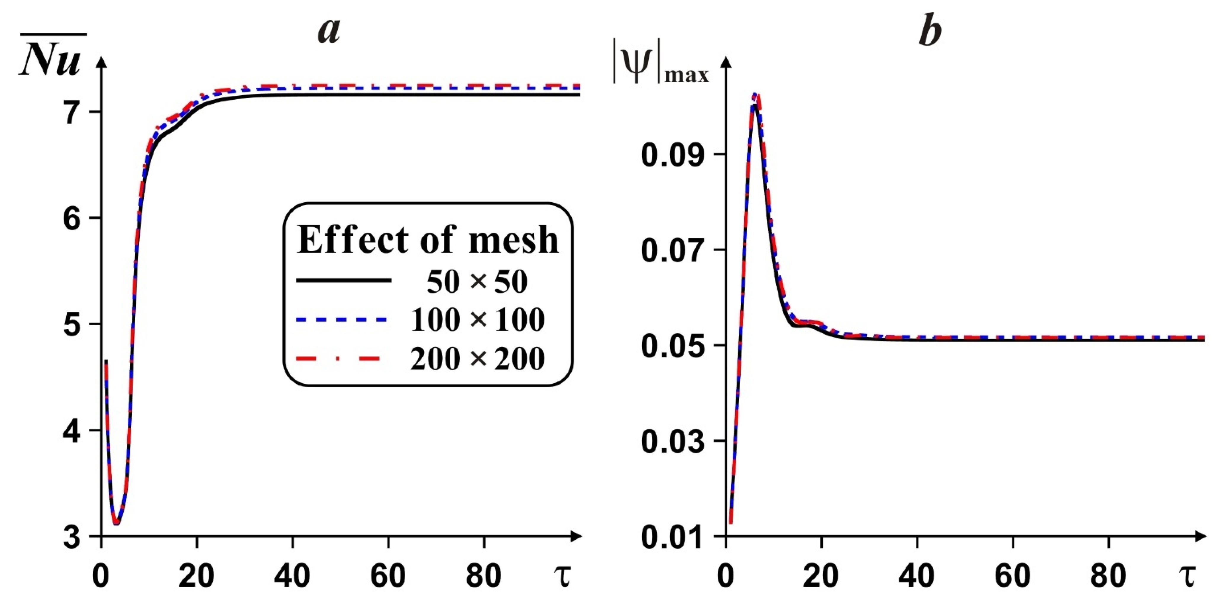
The developed computational algorithm was verified for various meshes in the case of one porous copper fin placed in the center of the left vertical border at Ra = 105, Pr = 0.71, Da = 10−2 and ε = 0.9. Figure 2 demonstrates the influence of the mesh characteristics on the mean Nusselt number and fluid flow rate. Comparing values of the average Nusselt number and fluid flow rate at steady state for different mesh parameters, we have , , and , , . Taking into account small differences between the considered meshes for and , e.g., and , and time consuming calculations for the mesh of 200 × 200 elements, the uniform mesh of 100 × 100 elements was chosen for the numerical simulation of the fins’ influence on heat transfer performance due to good accuracy and resolution.
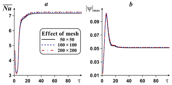
Figure 2.
Evolution in time of mean Nusselt number (a) and fluid flow rate (b) with mesh parameters for Ra = 105, Pr = 0.71, Da = 10−2 and ε = 0.9.
4. Results and Discussion
Numerical analysis was performed for Ra = 105, Pr = 0.71, solid and porous fins, Da = 10−4–10−2, ε = 0.9, h/L = 0.1, different numbers of fins (N), locations of fins (described by δ1 = d1/L, the non-dimensional distance between the bottom wall and bottom border of the nearest fin, and δ2 = d2/L, the non-dimensional distance between the upper border of one fin and the bottom border of the nearest fin) and lengths of fins (described by γ = l/L, the non-dimensional length of the fin). The material of solid fins is copper, while the material of porous fins is copper foam. The present investigation was devoted to the analysis of the impact of solid and porous fins and their characteristics on flow behavior and heat transfer in the chamber.
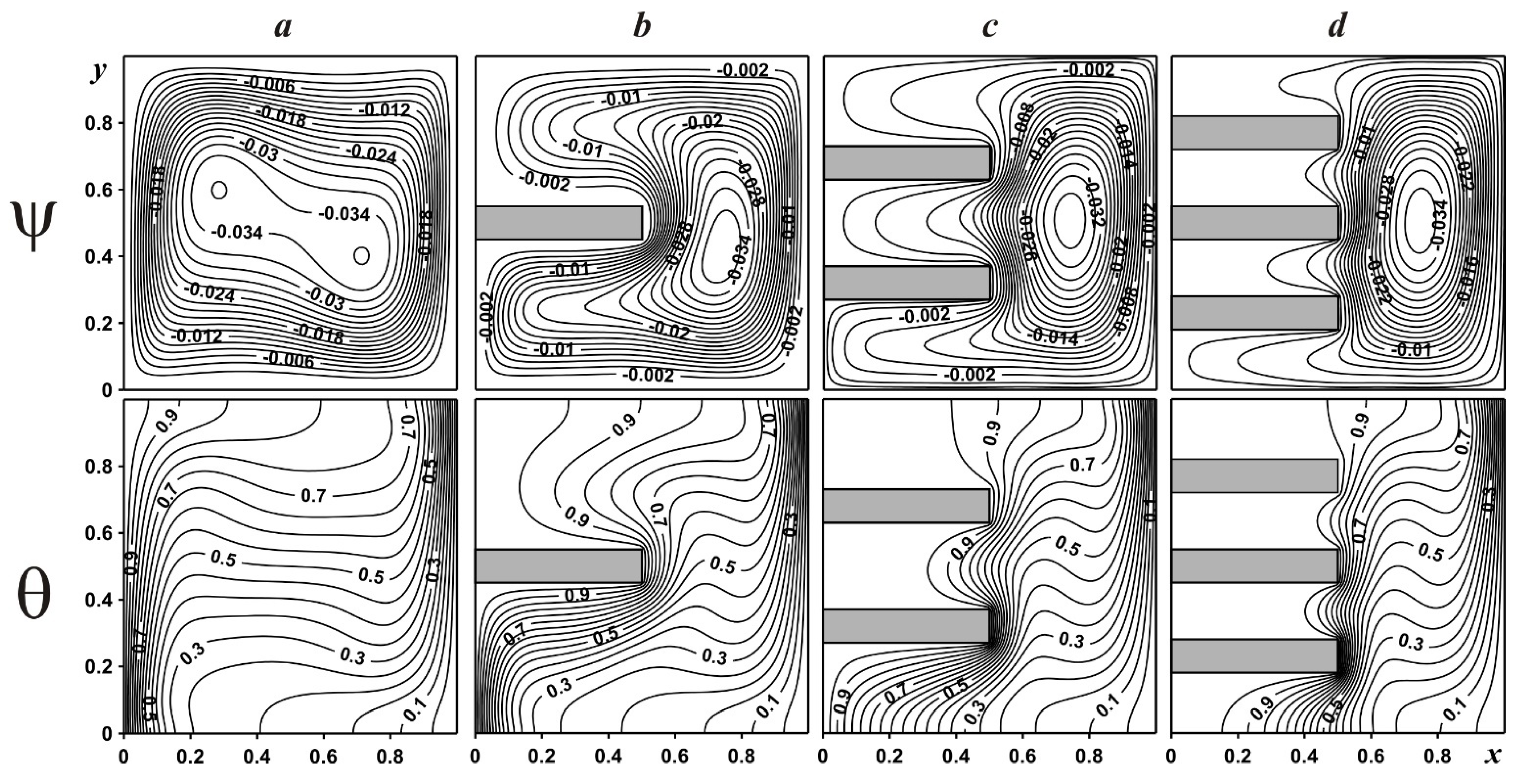
Figure 3 demonstrates streamlines and isotherms in a chamber without fins and with solid copper fins for Ra = 105, Pr = 0.71. In the case of a differentially heated clear cavity without fins (Figure 3a), one can find the formation of a typical flow structure that is known as “cat’s eyes” [23]. For this regime, an ascending flow is formed near the heated wall, and a descending flow can be found near the cooled border, while two oppositely rotating eddies are formed in the center of the cavity. At the same time, the temperature field illustrates the formation of two thermal boundary layers near two vertical walls with a stratified core in the central part, where heating occurs from the upper part to the bottom one. The addition of one solid fin (Figure 3b) acts as a natural obstacle that deforms the flow and leads to the formation of a single convective cell in the central part of the right half of the cavity. Such a flow structure is defined by significant heating of the upper part, not only from the left isothermal wall, but also from the solid fin of high thermal conductivity. Therefore, isotherms are not presented within this solid element. The further addition of solid fins to the cavity results in a different deformation of flow structure and more essential heating of the left half of the chamber. As a result, the fluid volume decreases with the inclusion of solid fins. It is worth noting that a huge temperature difference can be found on the vertical end of the bottom fin, where a high density of isotherms is monitored.
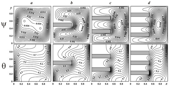
Figure 3.
Streamlines and isotherms in a cavity with solid fins: without fins (a); one fin (b); two fins (c); three fins (d).
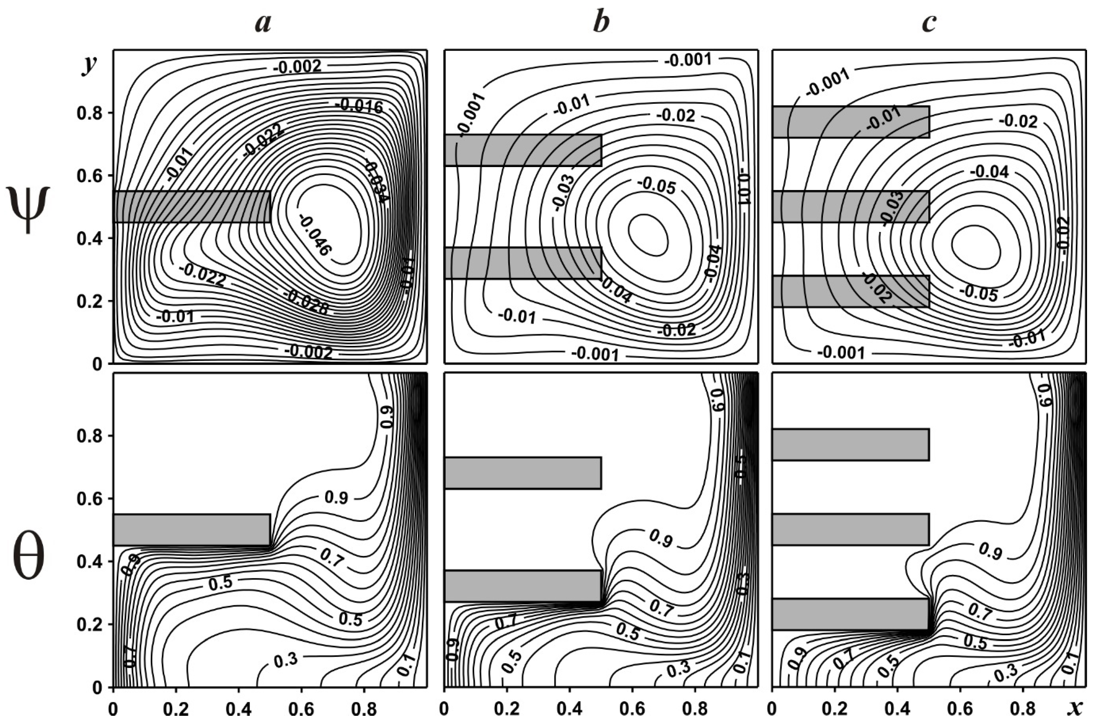
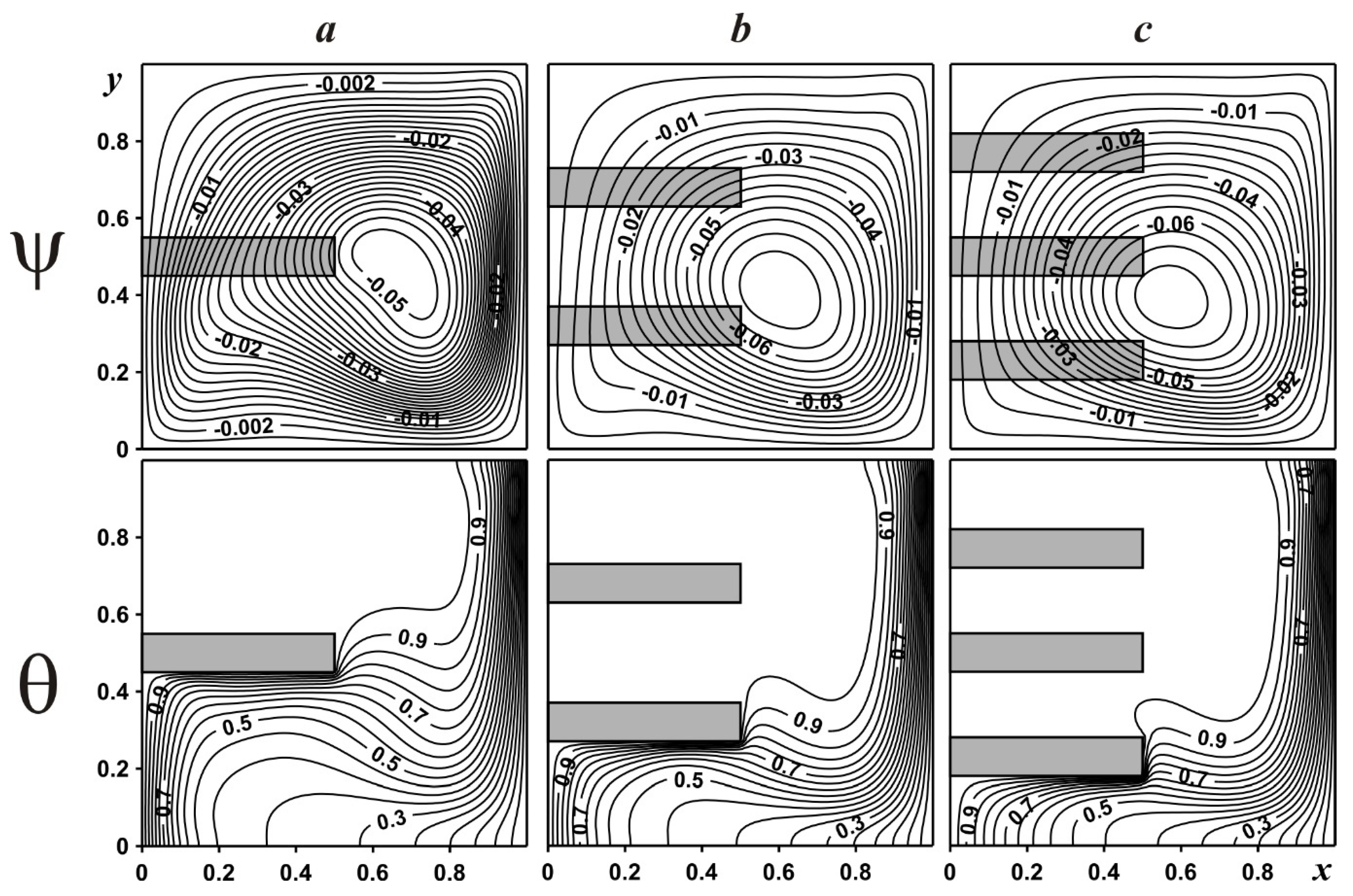
Figure 4 and Figure 5 demonstrate isolines of stream function and temperature within the enclosure with several porous fins for Da = 10−4 in Figure 4 and for Da = 10−2 in Figure 5. Porous fins are made of metallic copper foam with ε = 0.9. The addition of porous, permeable fins reduces flow resistance from this obstacle and also increases the heat transfer surface. Therefore, air can circulate not only within the chamber, but also within the porous material, and air flow strength, in this case, is greater than for solid fins (Figure 3). Moreover, the addition of porous fins allows for the intensification of the heat removal from the vertical heated surface, whilst air going through these fins moves heat away, and as a result, the upper part of the cavity is heated significantly. As it can be seen, the same effect could be obtained by using a single porous fin placed in the bottom part of the chamber.
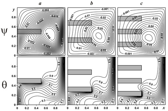
Figure 4.
Streamlines and isotherms in a cavity with porous copper fins at Da = 10−4: one fin (a); two fins (b); three fins (c).
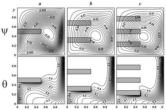
Figure 5.
Streamlines and isotherms in a cavity with porous copper fins at Da = 10−2: one fin (a); two fins (b); three fins (c).
An increment in the porous fin permeability (see Figure 5) results in the strengthening of the convective flow and heat transport within the cabinet. More essential heating of the chamber can be found for Da = 10−2 comparing Figure 4 and Figure 5 due to more intensive air circulation.
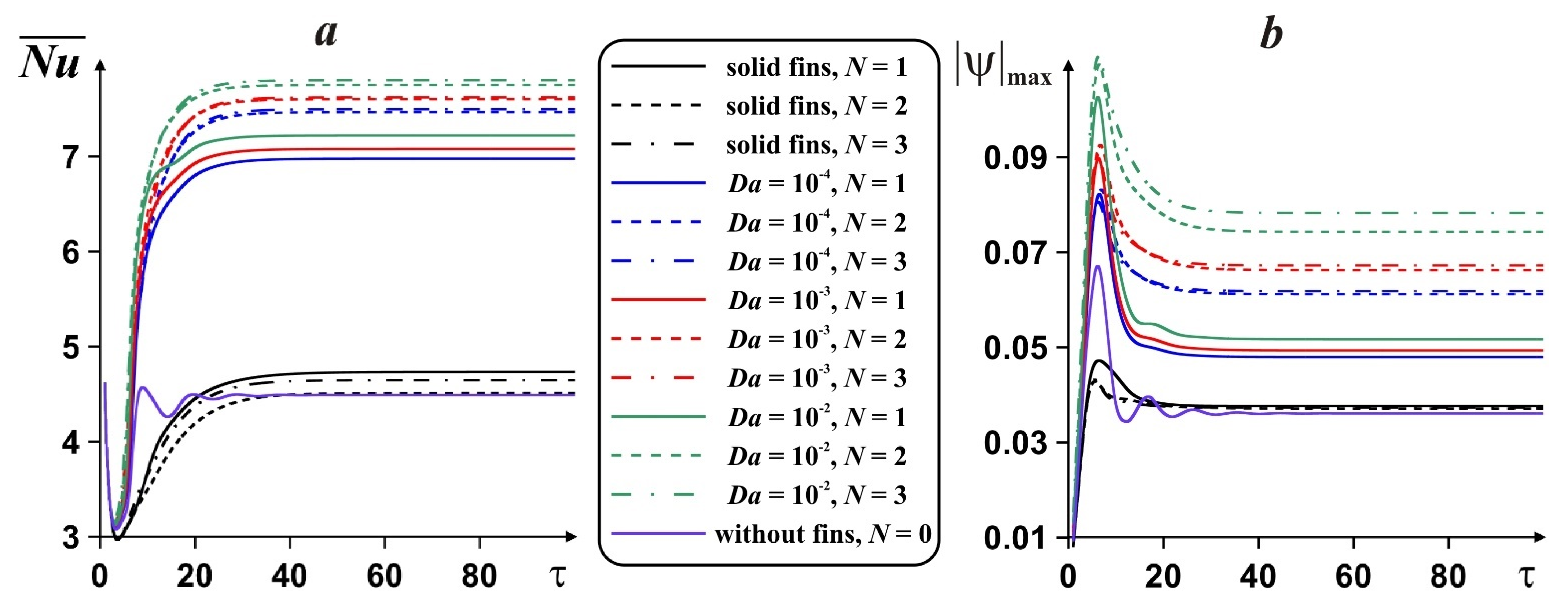
Figure 6 shows the time evolution of the average Nusselt number on the right vertical wall and air flow strength within the chamber with either solid or porous fins and without fins. It is interesting to note that the addition of solid or porous fins intensifies the heat removal, namely, the average Nusselt number increases. In the case of solid fins, this heat transfer enhancement is not so significant. Moreover, the addition of solid fins has a non-monotonic influence on the average Nusselt number, which illustrates an essential influence of the fins’ location on the heated vertical border. Whilst the use of porous fins achieves an increase in the average Nusselt number (for about 73%), solid fins lead to an increase of only 5%.
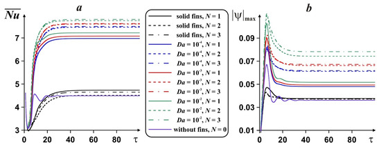
Figure 6.
Time evolution of average Nusselt number (a) and fluid flow rate (b) on number of fins, material of fins and Darcy number for porous fins.
An increase in the number of porous fins leads to an increase in the mean Nusselt number compared to the use of a single fin. The effect of using two fins in the increase in instead of one is much more intensive than that of using N = 3 instead of N = 2. An increase in the Darcy number results in enhancement of the energy transport rate. At the same time, the addition of solid fins causes a weak increment of air flow rate, while in the case of porous fins, one can find convective flow intensification that increases with the increase in Da and N.
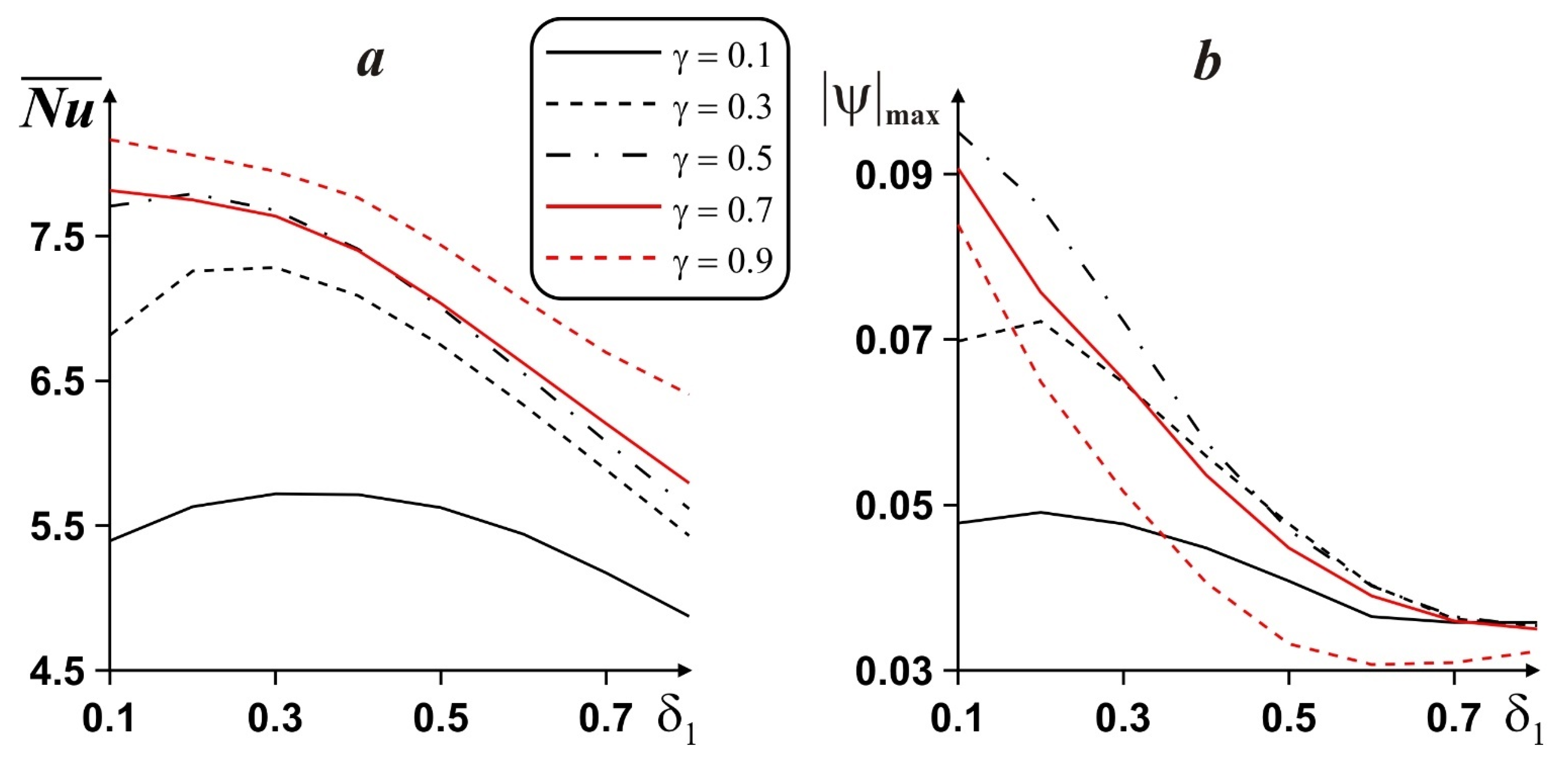
Taking into account a possible essential intensification of energy removal from the heated surface using porous fins, a more detailed analysis was performed for one and two porous fins with respect to the location and length of the fins. Figure 7 demonstrates the influence of one porous fin position and length on the average Nusselt number and air flow rate. In general, an increase in the porous fin length results in an intensification of convective heat transfer; however, between γ = 0.5 and γ = 0.7, some non-monotonic influence is observed. At the same time, for γ (= l/L) > 0.5 (see Figure 1), an increase in δ1 results in the minimization of the average Nusselt number, while in this case, maximum can be found for the lower value of δ1, i.e., δ1 = 0.1. Non-monotonic influence of δ1 is observed for γ < 0.5. In particular, an increase in γ from 0.1 to 0.5 illustrates a decrease in the y-coordinate of the fin’s location where the average Nusselt number has the maximum value. Namely, for γ = 0.1 maximum can be found for δ1 = 0.3, for γ = 0.3 maximum is achieved for δ1 = 0.3 and for γ = 0.5 maximum is achieved for δ1 = 0.2. As a result, more intensive heat removal from the vertical heated wall can be achieved by using a single long porous fin placed in the bottom part of this wall. The behavior of the air flow intensity with the mentioned parameters is shown in Figure 7b, where for γ > 0.3, the increase in δ1 results in a minimization of flow rate, whilst for γ = 0.1 and γ = 0.3 maximum can be found for δ1 = 0.2. At the same time, an increase in γ from 0.1 to 0.5 leads to a rise of , while an increase in γ from 0.5 to 0.9 leads to a reduction in .
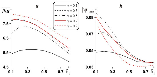
Figure 7.
Dependence of mean Nusselt number (a) and fluid flow rate (b) for one porous fin on distance from the bottom wall to the fin and length of the fin, for Da = 10−2.
Table 1 demonstrates the influence of the location and length of two porous fins on the average Nusselt number. As it has been mentioned in the case of one porous fin, the increase in the fin length leads to an increase in . For two fins with equal length (γ = 0.1), maximum can be achieved for δ1 = δ2 = 0.2, while for γ = 0.3 and γ = 0.5, maximum is achieved for δ1 = δ2 = 0.1. Such behavior has also been mentioned for one fin; namely, the increase in fin length leads to a reduction in the y-coordinate at the position where becomes maximum. At the same time, the use of two porous fins allows for the enhancement of heat removal by about 10%.

Table 1.
Average Nusselt number at vertical wall in the case of two porous fins for distance between fins, distance from the bottom wall to the first fin and length of fins when Da = 0.01.
5. Conclusions
Analysis of natural convection in a differentially heated chamber with solid or porous fins has been performed numerically using an in-house computational code developed with C++ programming language. The impact of fins with respect to their structure (solid or porous), number, length and location on the flow field and heat transport has been scrutinized. According to the obtained results, one can highlight that:
- -
- Porous fins are more effective for heat removal compared to solid fins. The addition of solid fins can raise the average Nusselt number by about 5%, while the corresponding increase for porous fins is about 73%;
- -
- An increase in the Darcy number and number of porous fins leads to an increase in the heat transfer rate;
- -
- An increase in fins’ length leads to a diminution of the y-coordinate for fins’ position with maximum ;
- -
- The addition of two porous fins enhances heat transfer by about 10%.
Author Contributions
Conceptualization, I.P. and M.A.S.; methodology, M.A.S.; formal analysis, L.X.H.K. and M.A.S.; investigation, L.X.H.K. and M.A.S.; writing—original draft preparation, L.X.H.K., I.P. and M.A.S.; writing—review and editing, L.X.H.K., I.P. and M.A.S.; supervision, M.A.S. All authors have read and agreed to the published version of the manuscript.
Funding
The work was supported by the Grants Council (under the President of the Russian Federation), Grant No. MD-5799.2021.4.
Institutional Review Board Statement
Not applicable.
Informed Consent Statement
Not applicable.
Data Availability Statement
All data are presented in this article.
Conflicts of Interest
The authors declare no conflict of interest.
Abbreviation
| Nomenclature | |
| C | heat capacity |
| d1 | distance between the bottom wall and nearest fin |
| d2 | distance between first and second fins |
| Da | Darcy number |
| g | acceleration due to gravity |
| H | thickness of the fin |
| k | thermal conductivity |
| K | porous medium permeability |
| l | length of the fins |
| L | cavity size |
| N | number of fins |
| Nu | Nusselt number |
| p | pressure |
| Pr | Prandtl number |
| Ra | Rayleigh number |
| t | time |
| T | temperature |
| Tc | cooled wall temperature |
| Th | heated wall temperature |
| , | velocity components |
| u, v | non-dimensional velocity components |
| , | Cartesian coordinates |
| x, y | non-dimensional Cartesian coordinates |
| Greek Symbols | |
| α | thermal diffusivity |
| β | thermal expansion parameter |
| δ1 | non-dimensional distance between the bottom wall and nearest fin |
| δ2 | non-dimensional distance between first and second fins |
| ε | porous medium porosity |
| θ | non-dimensional temperature |
| μ | dynamic viscosity |
| ρ | density |
| τ | non-dimensional time |
| stream function | |
| ψ | non-dimensional stream function |
| vorticity | |
| ω | non-dimensional vorticity |
| Subscripts | |
| f | fluid |
| hs | heat source |
| pm | porous medium |
| s | solid |
| spm | solid matrix of the porous medium |
References
- Sadeghianjahromi, A.; Wang, C.-C. Heat transfer enhancement in fin-and-tube heat exchangers—A review on different mechanisms. Renew. Sustain. Energy Rev. 2021, 137, 110470. [Google Scholar] [CrossRef]
- Husain, S.; Khan, S.A. A review on heat transfer enhancement techniques during natural convection in vertical annular geometry. Clean. Eng. Technol. 2021, 5, 100333. [Google Scholar] [CrossRef]
- Pandya, N.S.; Shah, H.; Molana, M.; Tiwari, A.K. Heat transfer enhancement with nanofluids in plate heat exchangers: A comprehensive review. Eur. J. Mech. B Fluids 2020, 81, 173–190. [Google Scholar] [CrossRef]
- Gong, L.; Li, Y.; Bai, Z.; Xu, M. Thermal performance of micro-channel heat sink with metallic porous/solid compound fin design. Appl. Therm. Eng. 2018, 137, 288–295. [Google Scholar] [CrossRef]
- Kumar, D.S.; Jayavel, S. Optimization of porous fin location and investigation of porosity and permeability effects on hydro-thermal behavior of rectangular microchannel heat sink. Int. Commun. Heat Mass Transf. 2021, 129, 105737. [Google Scholar] [CrossRef]
- Ranjbar, A.M.; Pouransari, Z.; Siavashi, M. Improved design of heat sink including porous pin fins with different arrangements: A numerical turbulent flow and heat transfer study. Appl. Therm. Eng. 2021, 198, 117519. [Google Scholar] [CrossRef]
- Vatanparast, M.A.; Hossainpour, S.; Keyhani-Asl, A.; Forouzi, S. Numerical investigation of total entropy generation in a rectangular channel with staggered semi-porous fins. Int. Commun. Heat Mass Transf. 2020, 111, 104446. [Google Scholar] [CrossRef]
- Kansara, R.; Patha, M.; Patel, V.K. Performance assessment of flat-plate solar collector with internal fins and porous media through an integrated approach of CFD and experimentation. Int. J. Therm. Sci. 2021, 165, 106932. [Google Scholar] [CrossRef]
- Zhang, J.; Han, H.Z.; Li, Z.R.; Zhong, H.G. Effect of pin-fin forms on flow and cooling characteristics of three-layer porous laminate. Appl. Therm. Eng. 2021, 194, 117084. [Google Scholar] [CrossRef]
- Yerramalle, V.; Premachandran, B.; Talukdar, P. Mixed convection from a heat source in a channel with a porous insert: A numerical analysis based on local thermal non-equilibrium model. Therm. Sci. Eng. Prog. 2021, 25, 101010. [Google Scholar] [CrossRef]
- Alshuraiaan, B.; Khanafer, K. The effect of the position of the heated thin porous fin on the laminar natural convection heat transfer in a differentially heated cavity. Int. Commun. Heat Mass Transf. 2016, 78, 190–199. [Google Scholar] [CrossRef]
- Martin, E.; Sastre, F.; Velazquez, A.; Bairi, A. Heat transfer enhancement around a finned vertical antenna by means of porous media saturated with Water-Copper nanofluid. Case Stud. Therm. Eng. 2021, 28, 101555. [Google Scholar] [CrossRef]
- Keramat, F.; Azari, A.; Rahideh, H.; Abbasi, M. A CFD parametric analysis of natural convection in an H-shaped cavity with two-sided inclined porous fins. J. Taiwan Inst. Chem. Eng. 2020, 114, 142–152. [Google Scholar] [CrossRef]
- Asl, K.A.; Hossainpour, S.; Rashidi, M.M.; Sheremet, M.A.; Yang, Z. Comprehensive investigation of solid and porous fins influence on natural convection in an inclined rectangular enclosure. Int. J. Heat Mass Transf. 2019, 133, 729–744. [Google Scholar]
- Aly, A.M.; Mohamed, E.M.; Alsedais, N. The magnetic field on a nanofluid flow within a finned cavity containing solid particles. Case Stud. Therm. Eng. 2021, 25, 100945. [Google Scholar] [CrossRef]
- Tu, J.; Qi, C.; Tang, Z.; Tian, Z.; Chen, L. Experimental study on the influence of bionic channel structure and nanofluids on power generation characteristics of waste heat utilisation equipment. Appl. Therm. Eng. 2022, 202, 117893. [Google Scholar] [CrossRef]
- Tu, J.; Qi, C.; Li, K.; Tang, Z. Numerical analysis of flow and heat characteristic around micro-ribbed tube in heat exchanger system. Powder Technol. 2022, 395, 562–583. [Google Scholar] [CrossRef]
- Tang, J.; Qi, C.; Ding, Z.; Afrand, M.; Yan, Y. Thermo-hydraulic performance of nanofluids in a bionic heat sink. Int. Commun. Heat Mass Transf. 2021, 127, 105492. [Google Scholar] [CrossRef]
- Astanina, M.S.; Rashidi, M.M.; Sheremet, M.A.; Lorenzini, G. Cooling system with porous finned heat sink for heat-generating element. Transp. Porous Media 2020, 133, 459–478. [Google Scholar] [CrossRef]
- Sheremet, M.A.; Rashidi, M.M. Thermal convection of nano-liquid in an electronic cabinet with finned heat sink and heat generating element. Alex. Eng. J. 2021, 60, 2769–2778. [Google Scholar] [CrossRef]
- Sheremet, M.A.; Trifonova, T.A. Unsteady conjugate natural convection in a vertical cylinder partially filled with a porous medium. Numer. Heat Transf. A 2013, 64, 994–1015. [Google Scholar] [CrossRef]
- Loenko, D.S.; Sheremet, M.A. Regularization models for natural convection of a pseudoplastic liquid in a closed differentially heated cavity. Bull. Perm Univ. Phys. 2021, 3, 13–22. [Google Scholar] [CrossRef]
- Vahl Davis, G. Natural convection of air in a square cavity: A bench mark numerical solution. Int. J. Numer. Methods Fluids 1983, 3, 249–264. [Google Scholar] [CrossRef]
Publisher’s Note: MDPI stays neutral with regard to jurisdictional claims in published maps and institutional affiliations. |
© 2022 by the authors. Licensee MDPI, Basel, Switzerland. This article is an open access article distributed under the terms and conditions of the Creative Commons Attribution (CC BY) license (https://creativecommons.org/licenses/by/4.0/).

