Abstract
Due to the significant advantages of a high torque density, better fault tolerance and high efficiency, the combined star–pentagon winding has recently gained researchers’ interest. In this paper, a simple method to identify the sequence of phases of a five-phase machine with combined star–pentagon winding was proposed. This was accomplished using resistance measurements between adjacent and non-adjacent phases. The analysis was conducted to clarify the phase sequence identification method. A case study of a 5.5 kW five-phase synchronous reluctance motor with combined star–pentagon winding was considered to simply apply the proposed method using an LCR meter for resistance measurements. The parasitic and wire resistances are dominant in the studied case, and this did not influence the accuracy of this method.
Keywords:
combined star–pentagon winding; five-phase machines; measurements; ohmmeter; phase sequence MSC:
00A71
1. Introduction
The current advances in the field of multiphase machines helped them to be one of the topics of significant interest to researchers in the field of variable speed drive systems [1,2,3,4,5]. Multiphase machines are preferred in some applications due to their noteworthy advantages compared to three-phase machines [6,7]. Five-phase machines have been favored compared to other multiphase machines, e.g., six and seven-phase machines [8,9]. This is largely because of the reduced size of the power converter. In the literature, it was found that the five-phase Induction machine can maintain about 70% of the rated torque with one-phase opened, while the asymmetrical six-phase machine works at only 66% of the rated torque [10,11]. There has been much interest in improving the performance of the five-phase machines. One of the key strategies that were used to improve the torque density of the five-phase machines is increasing the fundamental winding factor and the magnitude of the fundamental component of the magnetomotive force (MMF). This was achieved using innovative winding configurations [12,13,14,15]. Several research activities were conducted to improve the performance of five-phase machines using different types of winding configurations [16,17,18,19]. A combined star–pentagon configuration is one of the possibilities to obtain improved performance in five-phase machines. It was demonstrated that using a dual five-phase winding configuration connected in a combined star–pentagon reduces the losses of the induced eddy currents in the permanent magnets and in the rotor core while maintaining the five-phase terminals as in the traditional five-phase connections. The combined star–pentagon winding provides the required phase shift between the two windings (18°) to cancel all harmonics below the MMF component that generates the torque [20,21,22,23,24]. In [20], it was found that the output power of the five-phase induction machine with the combined star–pentagon winding with one phase opened was increased by about 16% compared to the star-connected winding. A dynamic and a steady state model for the combined star–pentagon winding were studied in [21,22]. In [23], a 20-slot/18-pole permanent magnet (PM) machine was introduced with a combined star–pentagon configuration. The torque density was increased by about 1.2% under healthy operating conditions compared to the star-connected winding. In [25], the average torque of a five-phase synchronous reluctance motor (synchronous reluctance motor) was increased by about 17% with combined star–pentagon winding compared to the three-phase star-connected winding.
The focus of this paper was electrical machines that are rewound with the combined star–pentagon winding. The first step after rewinding the machine is to identify the sequence of phases so that it can be correctly connected to the power converter. The conventional and common method [26,27,28] is to couple the tested machine to a prime mover and connect a capacitor bank in parallel with the tested machine to help the voltage build up. In this method, the tested machine works as a generator. A multi-channel oscilloscope is required to display the induced voltages of the tested machine, and hence the sequence of phases is identified. It was noticed that the capacitor bank could be removed in the case of a PM rotor or using a separate supply to magnetize the steel of the machine, as in [27,28]. The authors of [29] presented an approach for automatically detecting and correcting erroneous phase sequence connections. For the work in [29], current controllers in the simultaneously revolving and stationary reference frames were studied. The investigation was carried out for three-phase balanced and sinusoidal grid voltage operating conditions. Smart meters have completely covered the low-voltage distribution network in recent years. Data-driven single-phase meter phase identification is a possibility because of the abundance of smart meter measurement data. Numerous research successes have been achieved in this area, mostly using two methodologies based on correlation analysis and clustering. References [30,31] used timing voltage correlation analysis for phase identification of single-phase meters in distribution networks as part of the correlation analysis-based technique. Despite the simplicity of this technique, the recognition accuracy might still be increased. A technique of phase identification based on gray correlation was presented in [32], and it is most suited to the case of limited datasets. In terms of clustering-based approaches, references [33,34,35] all clustered voltage or power curves for phase detection based on K-means or modified K-means algorithms, which were implemented. A phase identification approach based on t-SNE dimensionality reduction with Birch clustering was presented in reference [36]. In terms of accuracy, the clustering-based strategy surpasses the correlation analysis-based approach, but the unsupervised clustering method requires correct phase information of at least three meters to supply labels for the clustering results. As was discussed, these methods [26,27,28,29,30,31,32,33,34,35,36] were used for phase sequence identification; however, the sequence of phases was identified using several components and/or different strategies. These components may not be readily available. For example, the availability of a prime mover, capacitor bank and multi-channel oscilloscope, and in some cases, these components might not be available, especially in industrial locations.
The rewound combined star–pentagon introduced in [5] is a new winding that resulted in higher average torque and lower torque ripple compared to the star-connected winding. Moreover, this winding is important as it gives the old machine a second life with better performance. However, after refurbishing the old machine, the first step is identifying the sequence of phases so that the machine can be correctly connected to the inverter. This sequence could be identified using the conventional method, which is to run the machine as a generator and observe the waveforms of the induced voltages using a scope; then, the user can identify the sequence. However, some of the equipment needed for this method might not be available, e.g., a capacitor bank, etc. Therefore, the focus of this paper was to propose a simple method to identify the sequence of phases in a five-phase machine with combined star–pentagon winding. This method is cost and time efficient. This is performed using resistance measurements between adjacent and non-adjacent phases with the means of an LCR meter [37,38]. A case study of a 5.5 kW five-phase synchronous reluctance motor with combined star–pentagon winding was studied to clarify the steps to identify the sequence of phases. The proposed practical technique has not been previously introduced or published. Furthermore, the simplicity of this technique might be viewed as an advantage for the combined star–pentagon winding arrangements.
2. Proposed Method to Identify the Phase Sequence
This section introduces the steps of implementation of a combined star–pentagon winding and the required steps to identify the sequence of phases. In a five-phase machine of the stator of S-slots and 2P-poles, the number of slots per pole per phase (q) can be calculated from (1). In order to implement the combined star–pentagon winding, these slots per pole per phase (q) were divided into two groups, i.e., red and green colored inFigure 1. It is recommended to divide them into two equal parts as much as possible to obtain a maximum winding factor and an improved torque density [5]. The coils of each group are connected in series. The first group in each phase was star-connected, and the second group was pentagon-connected; then, the whole system was connected, as shown in Figure 2, to obtain the combined star–pentagon configuration. In (2), and represent the number of stator-slots occupied by coils that are star and pentagon-connected, respectively.
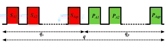
Figure 1.
Combined star–pentagon winding for one phase belt (phase A).
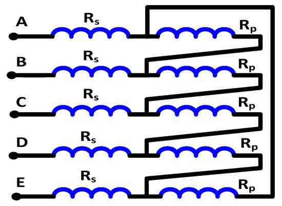
Figure 2.
Combined star–pentagon connection.
The relation between the current in the star-connected winding and in the pentagon-connected winding can be given as follows:
where and represent the current in the star and in the pentagon winding, respectively.
In order to obtain the same MMF from the two windings, the relation between the number of turns in the two windings was calculated as in (4) [20]. Hence, the copper volume and the copper losses were the same as in the conventional star-connected five-phase machine.
where and represent the number of turs in the star and in the pentagon winding, respectively.
The phase shift between the two windings is 18°, as shown in Figure 3. Figure 4 shows that the combined star–pentagon synchronous reluctance motor (5ph-SP) outperforms the star-connected three-phase synchronous reluctance motor (3ph-S) and also the star-connected five-phase synchronous reluctance motor (5ph-S). The results of Figure 4 were obtained using 2D Ansys Maxwell transient simulations. The average torque and the torque ripples were recorded at different line currents and also at different current angles. It was proved that the combined star–pentagon synchronous reluctance motor achieves 13.35% higher torque compared to the three-phase one and 6.37% higher torque compared to the star-connected five-phase synchronous reluctance motor.
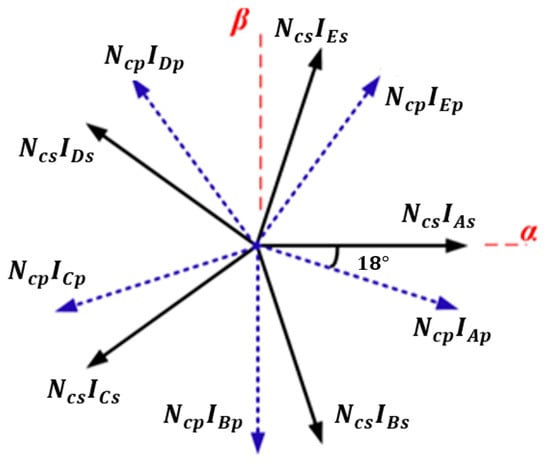
Figure 3.
Phasor diagram of the MMF magnitude in combined star–pentagon winding.

Figure 4.
Torque at different current and at optimal angles.
The method of identification of the sequence of phases is based on measuring the equivalent resistance between different terminals of the machine. In order to identify the sequence of phases in a combined star–pentagon winding, the equivalent circuit was analyzed in two cases, i.e., between two adjacent terminals and between two nonadjacent terminals. This is shown in Figure 5.
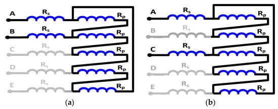
Figure 5.
Equivalent circuit of a combined star–pentagon winding measuring the resistance between (a) adjacent phases,, and (b) non-adjacent phases, .
The per-phase resistance of the star-connected winding is given by (5), and the per-phase resistance in the pentagon winding is given by (6). Based on the relation between the current in the star winding and the current in the pentagon winding, the relation between the conductor’s cross-sectional area can be described as in (7).
where a is the number of parallel circuits, is the copper resistivity and is the mean length of coil turn. and are the conductor cross-sectional area for the star and pentagon winding, respectively.
Figure 5a analyzes the equivalent resistance between two adjacent phases. The obtained equivalent resistance, in this case, can be described as in (8). The equivalent resistance between two nonadjacent phases is shown in Figure 5b and can be given by (9). Hence, the measured resistance in the case of the non-adjacent phases is higher than the measured resistance between the adjacent phases.
In order to identify the sequence of five phases, six readings must be recorded. This can be simply described in the following steps:
- The first terminal of the machine (consider it phase A) is connected to the positive terminal of the ohmmeter, and the negative terminal is connected to the other four terminals. The four readings of the ohmmeter will have two equal high values and two equal low values. The terminals that give the lower reading are the adjacent terminals (phases B and E) to the machine’s first terminal. Hence, the sequence of the three terminals of the five-phase machine (phases A, B and E) is known after performing the first step;
- In the second step, one of the adjacent terminals (select phase B) of the machine’s first terminal (phase A) is connected to the positive terminal of the ohmmeter, and the other terminal of the ohmmeter is connected to the other two terminals of the machine (nonadjacent terminals to the machine first terminal) (phases C and D). The terminal that gives the lower reading is the adjacent terminal (phase C) to the connected one (phase B) to the ohmmeter positive terminal. Hence, the sequence of phases is identified.
3. Case Study
In this section, a case study of a 5.5 kW five-phase synchronous reluctance motor with a combined star–pentagon winding, shown in Figure 6, was implemented to validate the introduced method to identify the phase sequence. This machine has low resistance values (around 0.2 ohm per phase) to check the validity and accuracy of the proposed method in terms of the determination of the phase sequence. The specification of the synchronous reluctance motor is summarized in Table 1 and Figure 7. As shown in Figure 6, there are five terminals for the five-phase synchronous reluctance motor with the combined star–pentagon configuration. The five terminals’ colors are red (r), black (k), green (g), yellow (y) and blue (b). An LCR meter was used to measure the winding resistance. As this is simply shown in Figure 8, the previously described steps to identify the sequence of phases were applied as follows:
- This terminal (red terminal or terminal that is considered as phase A) is connected to the positive terminal of the LCR meter, and the other terminal of the LCR meter is consecutively connected to the other four terminals of the machine (terminals k, g, y and b), as shown in Figure 10. The red terminal has two adjacent terminals and two nonadjacent terminals. Hence there are two higher values of resistance, and two lower values of resistance measured relative to the red terminal;
- However, it is not obvious which one of the yellow and the black terminals is phase C or D. In order to specify which one is phase C or D, the green terminal (phase B) is connected to the positive terminal of the LCR meter, and the other terminal of the LCR meter is connected once to the black terminal and once to the yellow terminal as shown in Figure 10. The terminal that gives the lower reading is the adjacent terminal to the green terminal (phase B);

Figure 6.
Photograph of a five-synchronous reluctance motor with LCR meter, (a) measurement resistance between two adjacent phases and (b) nonadjacent phases.
Figure 6.
Photograph of a five-synchronous reluctance motor with LCR meter, (a) measurement resistance between two adjacent phases and (b) nonadjacent phases.


Figure 7.
Cross-section of the five-phase SynRM.
Figure 7.
Cross-section of the five-phase SynRM.


Figure 8.
Flow chart of phases sequence identification.
Figure 8.
Flow chart of phases sequence identification.


Figure 9.
Steps of phases sequence identification represented in star of slot phasors, (a) phasors of phases before applying the first test, (b) the result of the first step and (c) the final result of the two setps. The question mark (?) means that the sequence order of this terminal is not identified yet.


Figure 10.
Detailed steps of phases sequence identification.
Figure 10.
Detailed steps of phases sequence identification.


Table 1.
The five-phase SynRM geometrical parameters.
Table 1.
The five-phase SynRM geometrical parameters.
| Parameter | Value | Parameter | Value |
|---|---|---|---|
| Stator bore diameter (D1O) | 110 mm | Air gap length (Lg) | 0.3 mm |
| Stator inner diameter (D) | 180 mm | Number of slots (S) | 36 |
| Rotor outer diameter (Dro) | 109.4 mm | Pole pairs (P) | 2 |
| Rotor inner diameter (Dri) | 35 mm | Rated frequency (F) | 100 Hz |
| Axial length (L) | 140 mm | Rated power (Pr) | 5.5 kW |
| Number of turns of star coil per phase | 24 | Number of turns of pentagon coil per phase | 29 |
| Stator/Rotor steel | M270-50A/M330-50A | Rated current (Is) | 12.3 A |
| Rotor flux barriers per pole (Nfb) | 3 | Number of phases (m) | 5 |
| ) | 0.25 | ) | 0.125 |
Table 2.
The obtained measured resistances.
Table 2.
The obtained measured resistances.
| Parameter | Value | Parameter | Value |
|---|---|---|---|
| Rrg | 0.365 Ω | Rry | 0.588 Ω |
| Rrb | 0.394 Ω | Rgk | 0.352 Ω |
| Rrk | 0.552 Ω | Rgy | 0.566 Ω |
Table 3.
The obtained sequence of phases.
Table 3.
The obtained sequence of phases.
| Terminal | Phase | Terminal | Phase |
|---|---|---|---|
| Red terminal | A | Yellow terminal | D |
| Green terminal | B | Blue terminal | E |
| Black terminal | C |
4. Comparative Analysis of the Proposed and Conventional Methods
This section analyses and compares the proposed method to identify the sequence of phases in five-phase combined star–pentagon machines with the conventional methods. As shown in Figure 11 and Table 4, there are many components required in the conventional method, such as a prime mover, capacitor bank and scope by which the researcher can observe the waveforms of the generated voltage of the examined machine (five-phase combined star–pentagon machine). Note that the examined machine works as a generator in this method, so the conventional method is considered a dynamic test approach. However, the proposed approach in this paper only uses the LCR meter for measuring the resistance between different terminals. Therefore, this method is considered more economical than conventional methods. In addition, there is no dynamic operation during the application of this method. Hence it is considered a static test. Moreover, the proposed method is cheaper than the conventional methods.
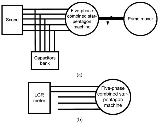
Figure 11.
(a) the conventional and (b) the proposed method to identify phase sequence in five-phase combined star–pentagon machine.
Table 4.
Comparison between the proposed and the conventional method of identification of phase sequence.
During the practical validation of this method, the errors in measurements and the parasitic inputs, which indeed existed, did not affect the correctness of the obtained sequence, and the performance of the motor with the identified phase sequence was tested under both speed and torque control mode with great agreements with its simulated performance. For the shortcuts, which did not exist in our case, if there is a shortcut, the obtained measurements will be totally different from what was expected, and the user will realize that there is a problem with the machine. Hence, this method can be considered as a checker for the status of the machine as well.
5. Conclusions
This paper proposed a simple, cost- and time-efficient method to identify the sequence of phases in a five-phase machine with a combined star–pentagon configuration. This method depends on measuring the resistance between the adjacent and the non-adjacent phases. The phases are identified using only six measurements. The effectiveness of the proposed method was proved in determining the sequence of the phases even at low resistance values. The parasitic and wire resistances are dominant in the studied case, and this does not influence the accuracy of the proposed method.
Author Contributions
Conceptualization, K.B.T.; methodology, K.B.T.; software, K.B.T.; validation, K.B.T.; investigation, K.B.T.; writing—original draft preparation, K.B.T.; writing—review and editing, M.N.I., A.M.E.-R. and P.S.; visualization, M.N.I., A.M.E.-R. and P.S.; supervision, M.N.I., A.M.E.-R. and P.S. All authors have read and agreed to the published version of the manuscript.
Funding
The authors acknowledge the Special Research Fund of Ghent University, Belgium (BOF019).
Data Availability Statement
Not applicable.
Conflicts of Interest
The authors declare no conflict of interest.
References
- Chen, Q.; Gu, L.; Lin, Z.; Liu, G. Extension of Space-Vector-Signal-Injection-Based MTPA Control into SVPWM Fault-Tolerant Operation for Five-Phase IPMSM. IEEE Trans. Ind. Electron. 2020, 67, 7321–7333. [Google Scholar] [CrossRef]
- Arafat, A.K.M.; Haque, M.S.; Islam, M.Z.; Choi, S. Performance Comparison at Maximum Torque per Ampere Control between Rare Earth and Rare Earth Free Five-phase PMa-SynRM Under Open Phase Faults. In Proceedings of the 2018 IEEE Energy Conversion Congress and Exposition (ECCE), Portland, OR, USA, 23–27 September 2018; pp. 784–789. [Google Scholar] [CrossRef]
- Tawfiq, K.B.; Ibrahim, M.N.; Sergeant, P. An Enhanced Fault-Tolerant Control of a Five-Phase Synchronous Reluctance Motor Fed From a Three-to-Five-Phase Matrix Converter. IEEE J. Emerg. Sel. Top. Power Electron. 2022, 10, 4182–4194. [Google Scholar] [CrossRef]
- Muteba, M. Influence of Mixed Stator Winding Configurations and Number of Rotor Flux-Barriers on Torque and Torque Ripple of Five-Phase Synchronous Reluctance Motors. In Proceedings of the 2019 IEEE Transportation Electrification Conference and Expo (ITEC), Novi, MI, USA, 19–21 June 2019; pp. 1–6. [Google Scholar] [CrossRef]
- Tawfiq, K.B.; Ibrahim, M.N.; El-Kholy, E.E.; Sergeant, P. Construction of Synchronous Reluctance Machines with Combined Star-Pentagon Configuration Using Standard Three-Phase Stator Frames. IEEE Trans. Ind. Electron. 2022, 69, 7582–7595. [Google Scholar] [CrossRef]
- Xu, L.; Fu, W. Evaluation of third harmonic component effects in five-phase synchronous reluctance motor drive using time-stepping finite-element method. IEEE Trans. Ind. Appl. 2002, 38, 638–644. [Google Scholar] [CrossRef]
- Tawfiq, K.B.; Ibrahim, M.N.; El-Kholy, E.E.; Sergeant, P. Comparative Analysis of Refurbishing Methods of Three-Phase Synchronous Reluctance Machines to Five-Phase With Minimum Cost. IEEE Trans. Ind. Appl. 2021, 57, 6007–6022. [Google Scholar] [CrossRef]
- Levi, E.; Bojoi, R.; Profumo, F.; Toliyat, H.A.; Williamson, S. Multiphase induction motor drives—A technology status review. IET Electr. Power Appl. 2007, 1, 489–516. [Google Scholar] [CrossRef]
- Tawfiq, K.B.; Ibrahim, M.N.; El-Kholy, E.E.; Sergeant, P. Refurbishing three-phase synchronous reluctance machines to multiphase machines. Electr. Eng. 2021, 103, 139–152. [Google Scholar] [CrossRef]
- Sala, G.; Mengoni, M.; Rizzoli, G.; Degano, M.; Zarri, L.; Tani, A. Impact of Star Connection Layouts on the Control of Multiphase Induction Motor Drives Under Open-Phase Fault. IEEE Trans. Power Electron. 2021, 36, 3717–3726. [Google Scholar] [CrossRef]
- Gary, E.; Magno, A.; Jorge, R. Design, Analysis and Validation of a Six-Phase Induction Machine from a Commercial Three-Phase for Academic Research. IEEE Lat. Am. Trans. 2020, 18, 1943–1952. [Google Scholar] [CrossRef]
- Farshadnia, M.; Cheema, M.A.M.; Pouramin, A.; Dutta, R.; Fletcher, J.E. Design of Optimal Winding Configurations for Symmetrical Multiphase Concentrated-Wound Surface-Mount PMSMs to Achieve Maximum Torque Density Under Current Harmonic Injection. IEEE Trans. Ind. Electron. 2018, 65, 1751–1761. [Google Scholar] [CrossRef]
- Abdel-Khalik, A.; Ahmed, S.; Hamad, M.; Massoud, A. Effect of Stator Winding Connection on Performance of Five-Phase Induction Machines. IEEE Trans. Ind. Electron. 2014, 61, 3–19. [Google Scholar] [CrossRef]
- Che, H.S.; Duran, M.J.; Levi, E.; Jones, M.; Hew, W.P.; Rahim, N.A. Postfault Operation of an Asymmetrical Six-Phase Induction Machine with Single and Two Isolated Neutral Points. IEEE Trans. Power Electron. 2014, 29, 5406–5416. [Google Scholar] [CrossRef]
- Mohammadpour, A.; Sadeghi, S.; Parsa, L. A Generalized Fault-Tolerant Control Strategy for Five-Phase PM Motor Drives Considering Star, Pentagon, and Pentacle Connections of Stator Windings. IEEE Trans. Ind. Electron. 2014, 61, 63–75. [Google Scholar] [CrossRef]
- Chen, H.; Liu, X.; El-Refaie, A.M.; Zhao, J.; Demerdash, N.A.O.; He, J. Comparative Study of Winding Configurations of a Five-Phase Flux-Switching PM Machine. IEEE Trans. Energy Convers. 2019, 34, 1792–1804. [Google Scholar] [CrossRef]
- Xu, H.; Huang, W.; Bu, F.; Liu, H.; Lin, X. Control of Five-Phase Dual Stator-Winding Induction Generator with an Open Phase. IEEE Trans. Ind. Electron. 2019, 66, 696–706. [Google Scholar] [CrossRef]
- Gu, Z.Y.; Wang, K.; Zhu, Z.Q.; Wu, Z.Z.; Liu, C.; Cao, R.W. Torque Improvement in Five-Phase Unequal Tooth SPM Machine by Injecting Third Harmonic Current. IEEE Trans. Veh. Technol. 2018, 67, 206–215. [Google Scholar] [CrossRef]
- Xu, H.; Bu, F.; Huang, W.; Hu, Y.; Liu, H. Control and Performance of Five-Phase Dual Stator-Winding Induction Generator DC Generating System. IEEE Trans. Ind. Electron. 2017, 64, 5276–5285. [Google Scholar] [CrossRef]
- Raziee, S.M.; Misir, O.; Ponick, B. Multiple Multiphase Combined Star–Polygon Winding Analysis. IEEE Trans. Ind. Electron. 2019, 66, 7468–7479. [Google Scholar] [CrossRef]
- Abdel-Khalik, A.S.; Elgenedy, M.A.; Ahmed, S.; Massoud, A.M. An Improved Fault-Tolerant Five-Phase Induction Machine Using a Combined Star/Pentagon Single Layer Stator Winding Connection. IEEE Trans. Ind. Electron. 2016, 63, 618–628. [Google Scholar] [CrossRef]
- Abdel-Khalik, A.S.; Ahmed, S.; Massoud, A.M. Dynamic Modelling of a Five-Phase Induction Machine with a Combined Star/Pentagon Stator Winding Connection. IEEE Trans. Energy Convers. 2016, 31, 1645–1656. [Google Scholar] [CrossRef]
- Abdel-Khalik, A.S.; Ahmed, S.; Massoud, A.M. Steady-State Mathematical Modelling of a Five-Phase Induction Machine with a Combined Star/Pentagon Stator Winding Connection. IEEE Trans. Ind. Electron. 2016, 63, 1331–1343. [Google Scholar] [CrossRef]
- Abdel-Khalik, A.S.; Ahmed, S.; Massoud, A.M. Low Space Harmonics Cancelation in Double-Layer Fractional Slot Winding Using Dual Multiphase Winding. IEEE Trans. Magn. 2015, 51, 8104710. [Google Scholar] [CrossRef]
- Tawfiq, K.B.; Ibrahim, M.N.; El-Kholy, E.E.; Sergeant, P. Performance Improvement of Existing Three Phase Synchronous Reluctance Machine: Stator Upgrading to 5-Phase with Combined Star-Pentagon Winding. IEEE Access 2020, 8, 143569–143583. [Google Scholar] [CrossRef]
- Teng, K.; Lu, Z.; Long, J.; Wang, Y.; Roskilly, A.P. Voltage Build-Up Analysis of Self-Excited Induction Generator with Multi-Timescale Reduced-Order Model. IEEE Access 2019, 7, 48003–48012. [Google Scholar] [CrossRef]
- Vanco, W.E.; Silva, F.B.; De Oliveira, C.M.R.; Monteiro, J.R.B.A.; De Oliveira, J.M.M. A Proposal of Expansion and Implementation in Isolated Generation Systems Using Self-Excited Induction Generator with Synchronous Generator. IEEE Access 2019, 7, 117188–117195. [Google Scholar] [CrossRef]
- Malik, N.H.; Mazi, A.A. Capacitance Requirements for Isolated Self-Excited Induction Generators. IEEE Power Eng. Rev. 1987, PER-7, 33–34. [Google Scholar]
- Chen, K.; Shi, J.; Wei, X.; Cai, S. Phase Identification with Single-Phase Meter and Concentrator Based on NMF Dimension Reduction and Label Propagation. In Proceedings of the 2021 IEEE 11th Annual International Conference on CYBER Technology in Automation, Control, and Intelligent Systems (CYBER), Jiaxian, China, 27–31 July 2021; pp. 1–6. [Google Scholar] [CrossRef]
- Mitra, R.; Kota, R.; Bandyopadhyay, S. Voltage Correlations in Smart Meter Data. In Proceedings of the 21th ACM SIGKDD International Conference on Knowledge Discovery and Data Mining, Sydney, Australia, 10–13 August 2015; pp. 1999–2008. [Google Scholar]
- Short, T.A. Advanced Metering for Phase Identification, Transformer Identification, and Secondary Modeling. IEEE Trans. Smart Grid 2013, 4, 651–658. [Google Scholar] [CrossRef]
- Li, G. Transformer topology identification method based on LoRa and GPU acceleration. Electr. Meas. Instrum. 2019, 21, 88–95. [Google Scholar]
- Hosseini, Z.S.; Khodaei, A.; Paaso, A. Machine Learning-Enabled Distribution Network Phase Identification. IEEE Trans. Power Syst. 2021, 36, 842–850. [Google Scholar] [CrossRef]
- Wang, W.; Yu, N.; Foggo, B.; Davis, J.; Li, J. Phase identification in electric power distribution systems by clustering of smart meter data. In Proceedings of the 2016 IEEE International Conference on Machine Learning and Applications (ICMLA), Anaheim, CA, USA, 18-20 December 2016; pp. 259–265. [Google Scholar]
- Ni, F.; Liu, J.Q.; Wei, F.; Zhu, C.D.; Xie, S.X. Phase identification in distribution systems by data mining methods. In Proceedings of the 2017 IEEE Conference on Energy Internet and Energy System Integration (EI2), Beijing, China, 26-28 November 2017; pp. 1–6. [Google Scholar]
- Lian, Z.; Yao, L.; Liu, S. Phase and meter box identification for single-phase users based on t-SNE dimension reduction and BIRCH clustering. Autom. Electr. Power Syst. 2020, 44, 176–184. [Google Scholar]
- Suzuki, K. A New Self-Calibration Method of an $LCR$ Meter for RF Resistance Calibration Using Capacitance Standards. IEEE Trans. Instrum. Meas. 2009, 58, 993–996. [Google Scholar] [CrossRef]
- Ibrahim, M.; Pillay, P. The Loss of Self-Excitation Capability in Stand-Alone Synchronous Reluctance Generators. IEEE Trans. Ind. Appl. 2018, 54, 6290–6298. [Google Scholar] [CrossRef]


Publisher’s Note: MDPI stays neutral with regard to jurisdictional claims in published maps and institutional affiliations. |
© 2022 by the authors. Licensee MDPI, Basel, Switzerland. This article is an open access article distributed under the terms and conditions of the Creative Commons Attribution (CC BY) license (https://creativecommons.org/licenses/by/4.0/).