

Slow–Fast Dynamics Behaviors under the Comprehensive Effect of Rest Spike Bistability and Timescale Difference in a Filippov Slow–Fast Modified Chua’s Circuit Model

Abstract
:1. Introduction
- The bifurcation-induced transition mechanism, which means that the bifurcation structures of attractors in the fast subsystems can explain the transitions in bursting oscillations very well.
- Non-bifurcation-induced transition mechanism, which means that the transitions in bursting oscillations can only be attributed to the unique manifold structures rather than to the bifurcation structures.
2. Mathematical Model
3. Nonsmooth Dynamics Analyses
3.1. Equilibria and the Stabilities
- 1.
- if and ( and ), is a so-called admissible equilibrium (AE), and is restricted by ();
- 2.
- if and , then is a so-called pseudo equilibrium (PE) located in sliding region , and which is equal to the equilibrium of sliding subsystem (9);
- 3.
- if , and (, and ), is a so-called boundary equilibrium (BE) located on ().
3.2. Boundary Equilibrium Bifurcations
3.3. Tangencies and the Visibilities
- Quadratic tangency, also be called the fold point, can be observed when the two conditions and are satisfied, i.e.at which the trajectory driven by subsystem is tangent to sliding boundary . Furthermore, when , i.e., , it is a visible fold, while , i.e., , it is an invisible fold.
- Cubic tangency, also be called the cusp point, can be observed when the three conditions , and are satisfied, i.e.at which one sliding orbit is tangent to sliding boundary . Furthermore, it is a visible cusp point when , while it is a invisible cusp point when .
4. Numerical Studies
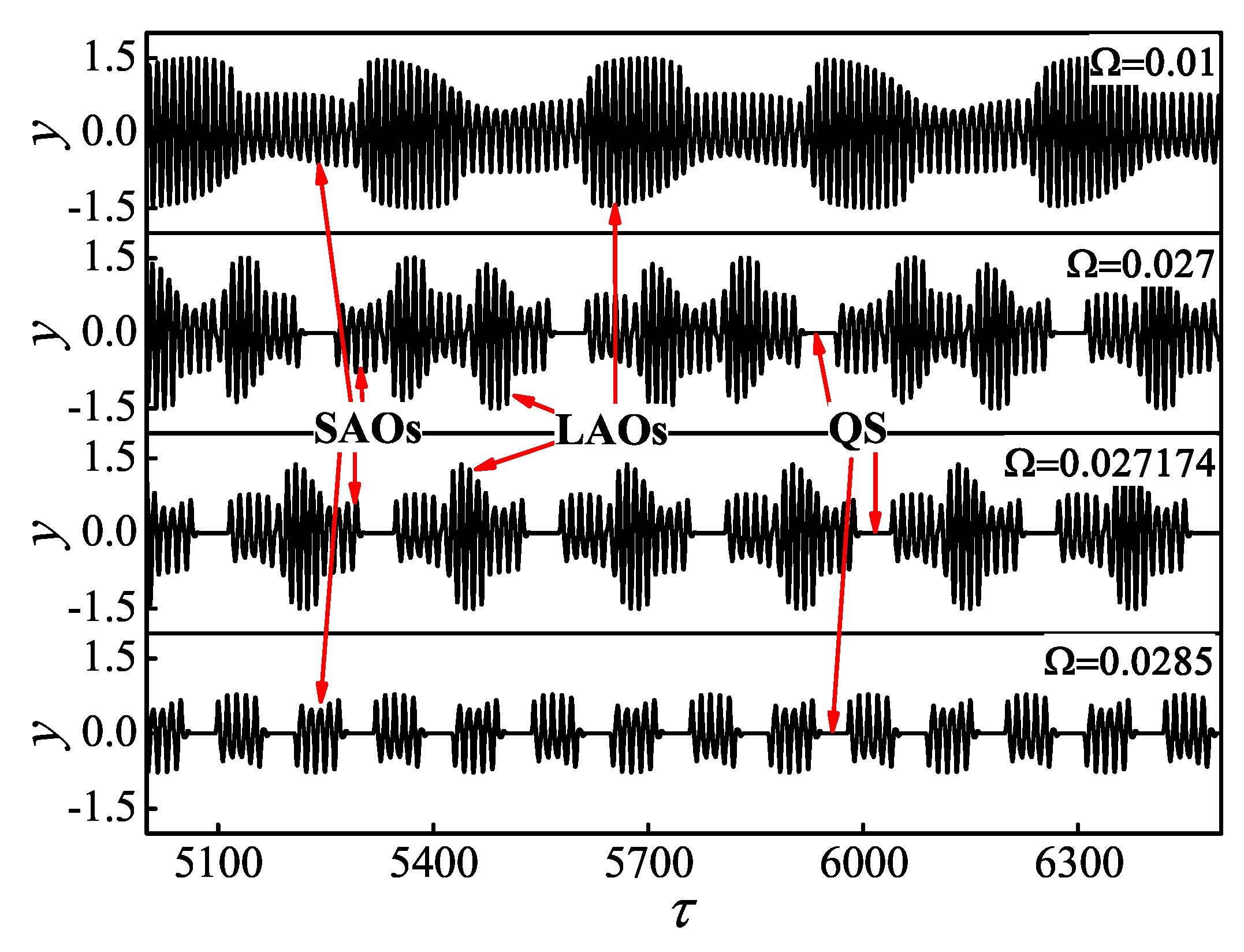
4.1. Generation Mechanism of MTSOs
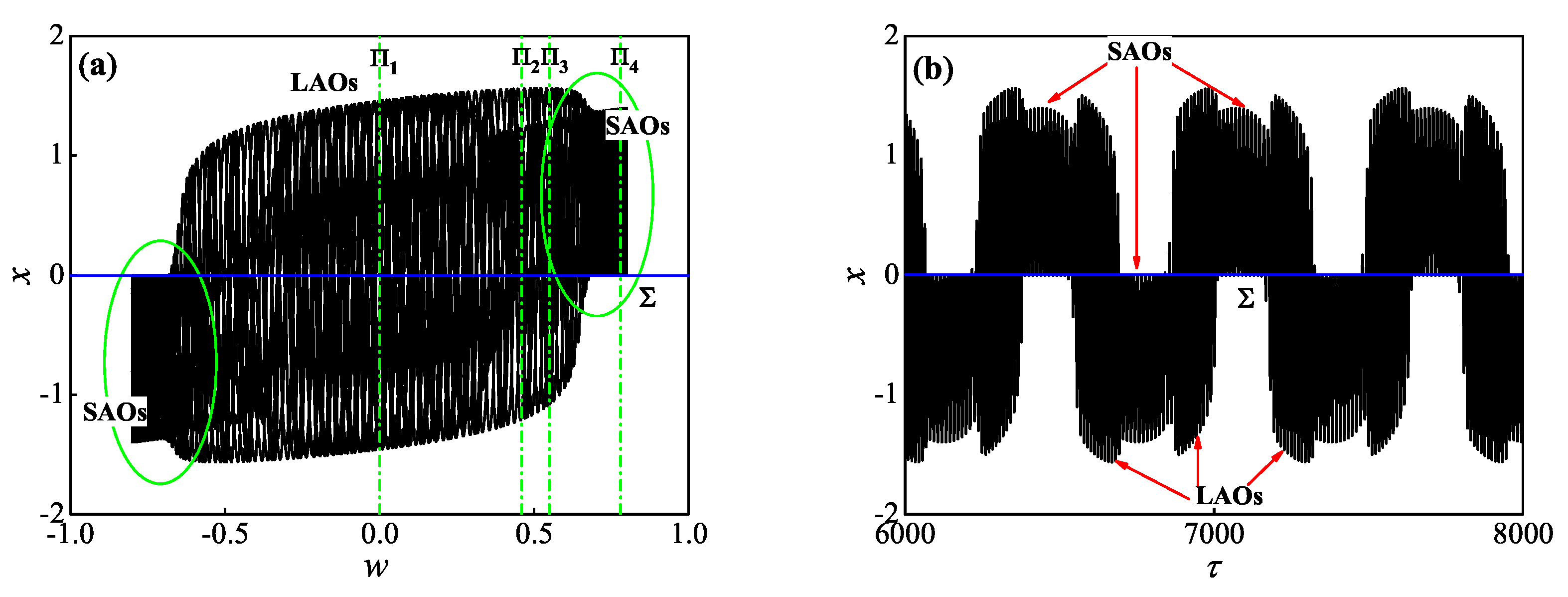
4.2. Generation Mechanism of MBOs and TBOs
- The regular transition route, meaning that the trajectory of the whole system will transition to from , and then to via the fold bifurcations of limit cycles, leading to the birth of mixed tonic spiking oscillation pattern;
- The irregular transition route, meaning that the trajectory of the whole system will transition to from via DSV effect, and then to via the nonsmooth fold bifurcations, leading to the birth of bursting oscillation pattern.
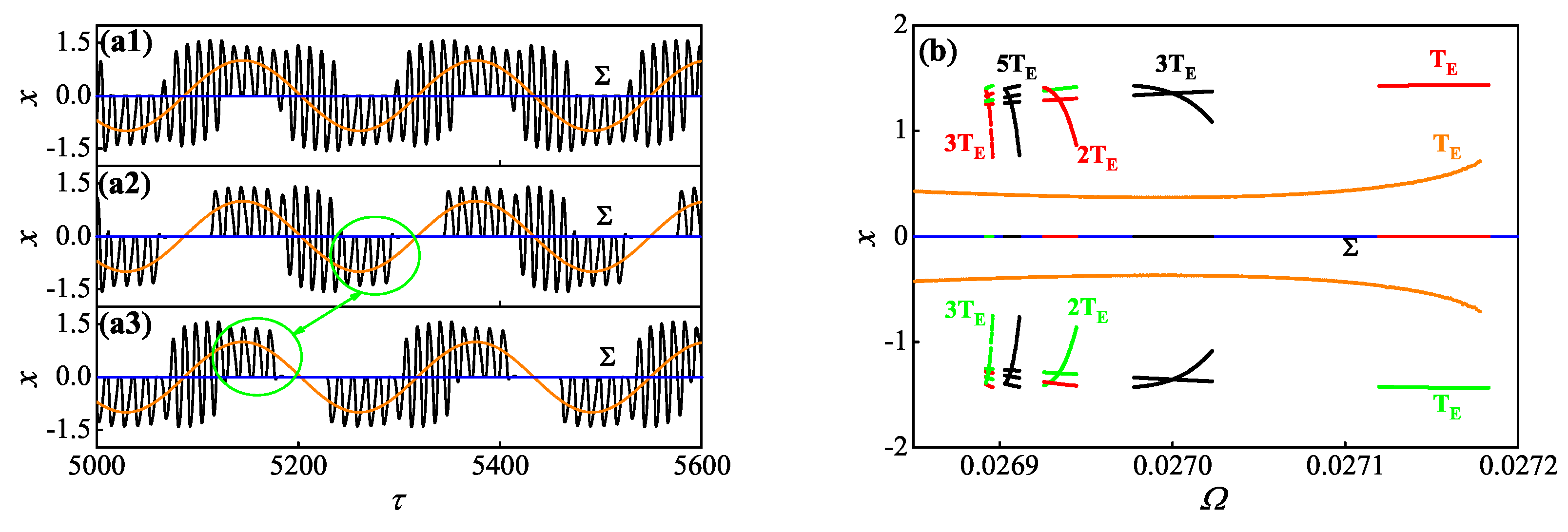
4.3. Coexistence of Whole System Responses
5. Conclusions and Discussions
- The combination form of the two coexisting transition routes may be random since the period-3 solution can be observed in the whole system responses, leading to various oscillation patterns such as multi-periodic and chaotic slow–fast dynamics behaviors.
- Interesting and various coexistences of whole system responses can also be observed. For instance, discontinuous alternations between bistability, tristability, and persistent tristability may be performed across the whole system.
Author Contributions
Funding
Institutional Review Board Statement
Informed Consent Statement
Data Availability Statement
Acknowledgments
Conflicts of Interest
References
- Chen, B.; Miller, P. Attractor-state itinerancy in neural circuits with synaptic depression. J. Math. Neurosci. 2020, 10, 15. [Google Scholar] [CrossRef] [PubMed]
- Curtu, R. Singular Hopf bifurcations and mixed-mode oscillations in a two-cell inhibitory neural network. Phys. D 2010, 239, 504–514. [Google Scholar] [CrossRef]
- Budzinski, R.C.; Lopes, S.R.; Masoller, C. Symbolic analysis of bursting dynamical regimes of Rulkov neural networks. Neurocomputing 2021, 441, 44–51. [Google Scholar] [CrossRef]
- Tepikin, A.V.; Petersen, O.H. Mechanisms of cellular calcium oscillations in secretory cells. BBA- Cell Res. 1992, 1137, 197–207. [Google Scholar] [CrossRef] [PubMed]
- Liu, P.; Liu, X.; Yu, P. Mixed-mode oscillations in a three-store calcium dynamics model. Commun. Nonlinear Sci. Numer. Simul. 2017, 52, 148–164. [Google Scholar] [CrossRef]
- Vishnevskii, A.L.; Elokhin, V.I.; Kutsovskaya, M.L. Dynamic model of self-oscillatory evolution in carbon monoxide oxidation over Pt(110). React. Kinet. Catal. Lett. 1993, 51, 211–217. [Google Scholar] [CrossRef]
- Li, X.; Bi, Q. Bursting oscillation in CO oxidation with small excitation and the enveloping slow-fast analysis method. Chin. Phys. B 2012, 21, 060505. [Google Scholar] [CrossRef]
- MacKay, L.; Lehman, E.; Khadra, A. Deciphering the dynamics of lamellipodium in a fish keratocytes model. J. Theor. Biol. 2020, 2020, 110534. [Google Scholar] [CrossRef]
- Barnhart, E.L.; Allard, J.; Lou, S.S.; Theriot, J.A.; Mogilner, A. Adhesion-dependent wave generation in crawling cells. Curr. Biol. 2017, 27, 27–38. [Google Scholar] [CrossRef] [Green Version]
- Bertram, R.; Rubin, J.E. Multi-timescale systems and fast–Slow analysis. Math. Biosci. 2016, 287, 105–121. [Google Scholar] [CrossRef]
- Prohens, R.; Teruel, A.E.; Vich, C. Slow–Fast n-dimensional piecewise linear differential systems. J. Differ. Equations 2016, 260, 1865–1892. [Google Scholar] [CrossRef]
- Rinzel, J.; Lee, Y.S. Dissection of a model for neuronal parabolic bursting. J. Math. Biol. 1987, 25, 653–675. [Google Scholar] [CrossRef]
- Rinzel, J. Formal classification of bursting mechanisms in excitable systems. In Lecture Notes in Biomathematics; Teramoto, E., Yamaguti, M., Eds.; Springer: Berlin/Heidelberg, Germany, 1987; pp. 267–281. [Google Scholar]
- Izhikevich, E.M. Neural excitability, spiking and bursting. Int. J. Bifurcat. Chaos 2012, 10, 1171–1266. [Google Scholar] [CrossRef] [Green Version]
- Han, X.; Bi, Q. Generation of hysteresis cycles with two and four jumps in a shape memory oscillator. Nonlinear Dyn. 2013, 72, 407–415. [Google Scholar] [CrossRef]
- Wang, Z.; Duan, L.; Cao, Q. Multi-stability involved mixed bursting within the coupled pre-Btzinger complex neurons. Chin. Phys. B 2018, 27, 070502. [Google Scholar] [CrossRef]
- Curtu, R.; Shpiro, A.; Rubin, N.; Rinzel, J. Mechanisms for frequency control in neuronal competition models. SIAM J. Appl. Dyn. Syst. 2008, 7, 609–649. [Google Scholar] [CrossRef] [Green Version]
- Buckthought, A.; Kirsch, L.E.; Fesi, J.D.; Mendola, J.D. Interocular grouping in perceptual rivalry localized with fMRI. Brain Topogr. 2021, 34, 323–336. [Google Scholar] [CrossRef]
- Cirillo, G.I.; Sepulchre, R. The geometry of rest-spike bistability. J. Math. Neurosci. 2020, 10, 13. [Google Scholar] [CrossRef]
- Kingston, S.L.; Thamilmaran, K. Bursting oscillations and mixed-mode oscillations in driven Liénard system. Int. J. Bifurcat. Chaos 2017, 27, 1730025. [Google Scholar] [CrossRef]
- Zhao, Y.; Liu, M.; Zhao, Y.; Duan, L. Dynamics of mixed bursting in coupled pre–Btzinger complex. Acta Phys. Sin.-Ch. Ed. 2021, 70, 120501. [Google Scholar] [CrossRef]
- SKuznetsov, Y.A. Elements of Applied Bifurcation Theory, 2nd ed.; Springer: New York, NY, USA, 2011. [Google Scholar]
- Liu, X.; Vlajic, N.; Long, X.; Meng, G.; Balachandran, B. Nonlinear motions of a flexible rotor with a drill bit: Stick-slip and delay effects. Nonlinear Dyn. 2013, 72, 61–73. [Google Scholar] [CrossRef]
- Moharrami, M.J.; de Martins, C.A.; Shiri, H. Nonlinear integrated dynamic analysis of drill strings under stick-slip vibration. Appl. Ocean Res. 2021, 108, 102521. [Google Scholar] [CrossRef]
- Depouhon, A.; Detournay, E. Instability regimes and self-excited vibrations in deep drilling systems. J. Sound Vib. 2014, 333, 2019–2039. [Google Scholar] [CrossRef] [Green Version]
- Yang, Y.; Liao, X. Filippov Hindmarsh-Rose Neuronal Model with Threshold Policy Control. IEEE T. Neur. Net Lear. 2018, 30, 1–6. [Google Scholar] [CrossRef]
- Wang, X.; Lin, X.; Dang, X. Supervised learning in spiking neural networks: A review of algorithms and evaluations. Neural Netw. 2020, 125, 258–280. [Google Scholar] [CrossRef]
- Kunze, M. Non-Smooth Dynamical Systems, 1st ed.; Springer: Berlin/Heidelberg, Germany, 2000. [Google Scholar]
- Bernardo, M.D.; Budd, C.J.; Champneys, A.R.; Kowalczyk, P. Piecewise-Smooth Dynamical Systems, 1st ed.; Springer: London, UK, 2008. [Google Scholar]
- Shen, B.; Zhang, Z. Complex bursting oscillations induced by bistable structure in a four-dimensional Filippov-type laser system. Pramana- Phys. Chaos 2021, 95, 97. [Google Scholar] [CrossRef]
- Han, H.; Bi, Q. Bursting oscillations as well as the mechanism in a Filippov system with parametric and external excitations. Int. J. Bifurcat. Chaos 2020, 30, 2050168. [Google Scholar] [CrossRef]
- Wang, Z.; Zhang, C.; Zhang, Z.; Bi, Q. Bursting oscillations with boundary homoclinic bifurcations in a Filippov-type Chua’s circuit. Pramana- Phys. 2020, 94, 95. [Google Scholar] [CrossRef]
- Qu, R.; Li, S. Attractor and vector structure analyses of bursting oscillation with sliding bifurcation in Filippov systems. Shock Vib. 2019, 2019, 1–10. [Google Scholar] [CrossRef] [Green Version]
- Li, S.; Han, H.; Qu, R.; Lv, W.; Bi, Q. Periodic bursting oscillations involving stick-slip motions as well as the generation mechanism in a Filippov type slow–fast dynamical system. Pramana–J. Phys. 2022; accepted. [Google Scholar]
- Han, X.; Bi, Q.; Kurths, J. Route to bursting via pulse-shaped explosion. Phys. Rev. E 2018, 98, 010201. [Google Scholar] [CrossRef]
- Wei, M.; Han, X.; Zhang, X.; Bi, Q. Bursting oscillations induced by bistable pulse-shaped explosion in a nonlinear oscillator with multiple-frequency slow excitations. Nonlinear Dyn. 2019, 99, 1301–1312. [Google Scholar] [CrossRef]
- Wei, M.; Jiang, W.; Ma, X.; Han, X.; Bi, Q. A new route to pulse-shaped explosion and its induced bursting dynamics. Nonlinear Dyn. 2021, 104, 4493–4503. [Google Scholar] [CrossRef]
- Hastings, A.; Abbott, K.C.; Cuddington, K.; Francis, T.; Gellner, G.; Lai, Y.C.; Morozov, A.; Petrovskii, S.; Scranton, K.; Zeeman, M.L. Transient phenomena in ecology. Science 2018, 361, 990. [Google Scholar] [CrossRef] [PubMed] [Green Version]
- Han, H.; Li, S.; Bi, Q. Non-smooth dynamics behaviors as well as the generation mechanisms in a modified Filippov type Chua’s circuit with a low-frequency external excitation. Mathematics 2022, 10, 3613. [Google Scholar] [CrossRef]
- Ginoux, J.M.; Llibre, J. Canards existence in memristor’s circuits. Qual. Theor. Dyn. Syst. 2016, 15, 383–431. [Google Scholar] [CrossRef] [Green Version]
- Marszalek, W.; Trzaska, Z. mixed-mode oscillations in a modified Chua’s circuit. Circ. Syst. Signal Pr. 2010, 29, 1075–1087. [Google Scholar] [CrossRef]
- Zhang, Z.; Chen, Z.; Bi, Q. Modified slow–Fast analysis method for slow–Fast dynamical systems with two scales in frequency domain. Theor. Appl. Mech. Lett. 2019, 9, 358–362. [Google Scholar] [CrossRef]
- Bernardo, M.D.; Kowalczyk, A.P.; Nordmarkb, A. Bifurcations of dynamical systems with sliding: Derivation of normal–form mappings. Physica D 2002, 170, 175–205. [Google Scholar] [CrossRef] [Green Version]
- Zhang, C.; Tang, Q. Complex periodic mixed-mode Oscillation patterns in a Filippov system. Mathematics 2022, 10, 673. [Google Scholar] [CrossRef]


| Dimensionless Parameter | Value |
|---|---|
| 1.63 | |
| a | −0.3 |
| b | 0.5 |
| −0.5 | |
| A | 0.8 |
| 0.6 |
| Bifurcation | Abbreviation | Parameter Value |
|---|---|---|
| Fold bifurcation of limit cycles | ||
| Multi-sliding bifurcation | ||
| Fold bifurcation of limit cycles |
| Sort | Attractor | Parameter Range | Border Bifurcation |
|---|---|---|---|
| I | , | , | |
| II | , | , | |
| III | , | , |
| Coexistence Type | Zone | Response Type |
|---|---|---|
| tristability | one period– MTSOs 1 and two period– MBOs 2 | |
| bistability | one period– MTSOs 1 and one period– MBOs 1 | |
| tristability | one period– MTSOs 1 and two period– MBOs 2 | |
| bistability | one period– MTSOs 1 and one period– MBOs 1 | |
| tristability | one period– MTSOs 1 and two period– MBOs 2 |
Publisher’s Note: MDPI stays neutral with regard to jurisdictional claims in published maps and institutional affiliations. |
© 2022 by the authors. Licensee MDPI, Basel, Switzerland. This article is an open access article distributed under the terms and conditions of the Creative Commons Attribution (CC BY) license (https://creativecommons.org/licenses/by/4.0/).
Share and Cite
Li, S.; Lv, W.; Chen, Z.; Xue, M.; Bi, Q. Slow–Fast Dynamics Behaviors under the Comprehensive Effect of Rest Spike Bistability and Timescale Difference in a Filippov Slow–Fast Modified Chua’s Circuit Model. Mathematics 2022, 10, 4606. https://doi.org/10.3390/math10234606
Li S, Lv W, Chen Z, Xue M, Bi Q. Slow–Fast Dynamics Behaviors under the Comprehensive Effect of Rest Spike Bistability and Timescale Difference in a Filippov Slow–Fast Modified Chua’s Circuit Model. Mathematics. 2022; 10(23):4606. https://doi.org/10.3390/math10234606
Chicago/Turabian StyleLi, Shaolong, Weipeng Lv, Zhenyang Chen, Miao Xue, and Qinsheng Bi. 2022. "Slow–Fast Dynamics Behaviors under the Comprehensive Effect of Rest Spike Bistability and Timescale Difference in a Filippov Slow–Fast Modified Chua’s Circuit Model" Mathematics 10, no. 23: 4606. https://doi.org/10.3390/math10234606