Article

Effect of a Novel Tooth Pitting Model on Mesh Stiffness and Vibration Response of Spur Gears

1
School of Mechanical, Electronic and Control Engineering, Beijing Jiaotong University, Beijing 100044, China
2
State Key Laboratory of Mechanical Behavior and System Safety of Traffic Engineering Structures, Shijiazhuang Tiedao University, Shijiazhuang 050043, China
3
School of Mechanical Engineering, Shijiazhuang Tiedao University, Shijiazhuang 050043, China
*
Author to whom correspondence should be addressed.
Mathematics 2022, 10(3), 471; https://doi.org/10.3390/math10030471
Submission received: 15 December 2021 / Revised: 22 January 2022 / Accepted: 28 January 2022 / Published: 31 January 2022
(This article belongs to the Special Issue Mathematical Method and Application of Machine Learning)

Abstract

:
The existence of pitting failure has a direct influence on the time-varying mesh stiffness (TVMS) and thus changes the vibration properties of the gears. The shape of pitting on the tooth surface is characterized by randomness and geometric complexity. The overlapping pitting shape has rarely been investigated, especially when the misalignment of gear base circle and root circle was considered. In this paper, the pitting shape is considered as approximately the union of several ellipse cylinders, in which the gear tooth is treated as a cantilever beam starting from the root circle. Then, the TVMS of perfect gear and that of gear with different pitting severity levels are solved by the potential energy method. The effect of pitting size on TVMS is discussed in detail. In addition, the vibration response in the frequency domain for the gear system is analyzed, and the effectiveness is qualitatively verified by comparing with the vibration signals of the experimental gearbox. The results indicate that the new pitting model overcomes the problem of ignoring the overlap between different pits and is more consistent with the actual situation. The presence of tooth pitting reduces the TVMS, and the complex sidebands appear around the gear mesh frequency and its harmonics. The proposed model can be used to predict the fluctuation of gear mesh stiffness when tooth pitting occurs, and the corresponding dynamic characteristics can provide the theoretical basis for gear condition monitoring and fault diagnosis.

1. Introduction

As one of the key components of mechanical transmission, spur gears have the characteristics of simple structure, convenient manufacture, reliable operation, and long service life and play an extremely important role in the process of power transmission. Spur gears have been used extensively in various mechanical fields [1,2,3,4]. However, due to the severity and complexity of operating conditions, there will inevitably be different degrees and types of failures in the operation of gear systems, such as tooth pitting, tooth root crack, tooth breaking, etc. [5,6,7,8,9]. Once the failure occurs, the TVMS of gear teeth is reduced, and the vibration of the transmission system is unstable, which directly affects the transmission precision and the running state of the whole mechanical equipment. Therefore, it is of great theoretical significance and engineering value to study the mechanism of gear failure and its influence on the dynamic responses of gear systems for early fault diagnosis, gear design, and safety maintenance in mechanical equipment.
Tooth pitting and tooth root crack are the most typical fatigue damages in gear transmission. They mainly lead to the abnormal vibration response of the system by changing the TVMS. Up to now, two main kinds of methods, the finite element method (FEM) [10,11,12] and the analytical method, have been adopted to calculate the TVMS of gear pairs. The analytical method has been widely used in the computation of TVMS due to its high efficiency and convenience, among which the potential energy method is one of the most commonly used analytical methods. In 1987, Yang [13] proposed the potential energy method for obtaining the TVMS. He considered the gear tooth as a cantilever of variable cross-section staring from the base circle and derived the analytical expressions of the stiffness of Hertzian contact, bending, and axial compressive. In 2004, Tian [14] took shear stiffness into account to improve the calculating precision of TVMS. In the same year, Sainsot [15] analyzed the effect of the gear body on tooth deflections. In recent years, based on the method mentioned above, the TVMS of gear without fault has been obtained by many researchers [16,17,18], and many scholars have studied the tooth crack fault of gears [19,20,21,22,23,24,25]. Because of the randomness and complexity of the morphology of pitting or spalling, geometric shapes such as cuboid, cylinder, sphere, and ellipsoid are often used to simulate pitting or spalling morphology to study and analyze the TVMS of gears take advantage of potential energy methods. The shape of pitting is regarded as cuboid; Chaari [26] calculated and compared the variation of TVMS of healthy gear and gear with pitting with respect to time, in which the Hertzian contact, axial compressive, and bending stiffness are considered. Focusing on the shear stiffness, Shawki [27] modeled the spalling as a cuboid and studied the effects of spalling on TVMS and the dynamic response of the wind turbine gearbox model. Ma [28] also regarded the shape of spalling as a cuboid and considered the bending stiffness, axial compressive stiffness, Hertzian contact stiffness, and shear stiffness to obtain the TVMS, which was verified by FEM. However, all the above studies assume that the gear tooth is a non-uniform cantilever beam staring from the base circle. For helical gears, Jiang [29] derived time-varying sliding friction and mesh stiffness for a spalling defect with cuboid shapes and discussed the effect of the spalling defect on the dynamic responses of this system. When pittings with different severity are distributed over adjacent multiple teeth, Liang [30] obtained the TVMS of gear with cylindrical tooth pitting, including bending, axial compressive stiffness, Hertzian contact stiffness, and shear stiffness. He [31] also researched the contribution of different pitting severity levels to TVMS when the number of teeth of both driving and driven gears is 19, where the tooth profile from the root circle to the base circle is simplified a straight line, and the tooth pits are shaped into circular. Lei [32] modeled the pitting as a series of cylinders with different sizes that followed uniform distribution along the tooth width and normal distribution along with the tooth height. The influence of tooth pitting on TVMS was obtained in detail and verified by comparison with the FEM. The number of teeth of both driving and driven gears is less than 42; Chen [33] described the gear teeth as a cantilever beam on the root circle, the pitting as a cylinder, and then proposed a novel two-dimensional Gaussian distribution model to present the distribution of pitting on the tooth surface. From the perspective of geometric deviations and tooth surface roughness changes caused by pitting, Luo [34] discussed the fault characteristics of pitting. The pitting shape is treated as a part of an ellipsoid; the change of effective section area and moment of inertia under different spalling failure conditions were analyzed [35]. Later, he [36] proposed a shape-independent method to form tooth spall based on defect ratios rather than a specific geometry, and the advantage of this method is that the function of defect ratios only needs to be modified for different shapes of spalling faults. The pitting was approximated to a part of the sphere, according to the changes of the depth and width of pitting; Meng [37] gave different evolution ways for a single pit and studied the influence of tooth pitting of different severity on TVMS and Hertzian contact stiffness. In the analysis of the TVMS with pitting or spalling based on the potential energy method above, the gear tooth is treated as a cantilever of variable cross-section starting from the root circle. In fact, the root and the base circles are misaligned according to the actual geometry of the gear tooth. For standard involute spur gears, the root circle is smaller if the tooth number is less than 42; otherwise, the root circle is bigger. In addition, the overlap between different pits with each other is rarely modeled on the TVMS and dynamic response of the gear system.
In order to supplement the shortcomings of the research mentioned above, it is necessary to develop a new tooth pitting model of the single-stage gear reducer and study its mechanism and influence on system response. The tooth pitting model is approximated as the union of several ellipse cylinders. The teeth of both driving and driven gears are described as variable cross-section cantilever beams starting from the root circle, in which the whole tooth profile is an involute profile under the condition that the base circle is less than the root circle; otherwise, the transition curve between the root circle and the base circle is approximated as an arc. In Section 2, a new pitting model is developed, and three fault levels are defined according to the distribution position and quantity of tooth pitting. The TVMS of gear without faults and gears with three pitting levels are calculated in Section 3. In Section 4, the fault characteristics of single-stage gear reducer with different degrees of tooth pitting are investigated and compared from simulation and experiment. Finally, the main conclusions of this paper are given.

2. Model of Tooth Pitting

For spur gear reducer, the driving gear has fewer teeth, and each tooth engages in the meshing more frequently than driven gear. In consequence, the driving gear is easier to suffer from fatigue damages than the driven gear. In this section, it is assumed that all teeth of the driven gear are perfect, while a local pitting fault exists on one of the teeth of the driving gear, and the other teeth are perfect. Each tooth pitting is approximated as a part of an elliptic cylinder ( a , b , δ ) where 2 a represents the length of the major axis (the tooth width direction), 2 b is the length of the minor axis (the tooth profile direction), and δ is the height, that is, the pitting area is considered as the union of multiple elliptic cylinders. The size, number, and position of pitting can be used to mimic different severity of pitting damages. Based on references [38,39,40], pitting often occurs near the pitch and then extends to other parts. Therefore, three pitting damage levels are modeled, as shown in Figure 1. Slight pitting: the union of nine elliptic cylinders, consisting of two shapes A and seven shapes B centered on the pitch line, plotted in Figure 1a. Moderate pitting: the union of 18 elliptic cylinders, consisting of 2 shape A and 16 shape B centered on the pitch line, plotted in Figure 1c. Severe pitting includes moderate pitting, 2 shapes A and 16 shapes B centered on the addendum as shown in Figure 1d. If the length of the major axis and that of the minor axis are equal, the pitting shape is part of the cylinder.

3. Calculation of TVMS

In this section, the potential energy principle [41] is selected to calculate the effective TVMS. The total potential energy stored in the transmission due to the deformation is mainly expressed as Hertzian energy, bending energy, shear energy, axial compressive energy, and fillet-foundation energy. The values of each stiffness corresponding to these energies can then be calculated.

3.1. Cantilever Beam Model for Gear Tooth

For the standard involute spur gears, when the number of teeth is 42, the radiuses of the base circle and the root circle are the same; otherwise, there are some differences between them. Based on the calculation formula of root circle and base circle radius, as shown in Equations (1) and (2), it can be calculated that the base circle and root circle remain the same when the number of gear teeth is 42 (41.45) with tip clearance coefficient c * = 0.25 , addendum coefficient h a * = 1 , and pressure angle α 0 = 20 ° . The base circle is smaller than the root circle when the number of gear teeth is greater than 42. The gear tooth is considered as a cantilever beam with variable cross-section on the root circle, where for the case that the base circle is more than the root circle, an arc is used to represent the transition curve between the two circles, and the whole tooth profile is treated as an involute profile for other cases demonstrated in Figure 2 and Figure 3, respectively.
R b = m z 2 cos α 0 ,
R f = m z 2 ( h a * + c * ) m .

3.2. Calculation of TVMS for a Healthy Gear Tooth

The total effective TVMS for single-tooth-pair meshing duration can be expressed as
k ts = 1 1 k h + ( 1 k b + 1 k s + 1 k a + 1 k f ) + ( 1 k ¯ b + 1 k ¯ s + 1 k ¯ a + 1 k ¯ f ) ,
where k b , k s , k a , and k f denote the bending stiffness, shear stiffness, axial compressive stiffness, and fillet-foundation stiffness of driving gear, respectively, k ¯ b , k ¯ s , k ¯ a , and k ¯ f are those of driven gear, and k h expresses the Hertzian contact stiffness.
Two pairs of gears engage simultaneously in the double-tooth-pair meshing duration, and the effective TVMS can be derived as
k td = i = 1 2 1 1 k h i + ( 1 k b i + 1 k s i + 1 k a i + 1 k f i ) + ( 1 k ¯ b i + 1 k ¯ s i + 1 k ¯ a i + 1 k ¯ f i ) ,
where i = 1 and i = 2 represent the first pair and the second pair of meshing teeth, respectively.
If the contact ratio of a pair of spur gears is greater than one and less than two, the whole process of engagement of the j th tooth contains three engagement regions: single-tooth engagement region B j , double-tooth engagement regions A j and C j , where θ 1 is the angular displacements of the driving gear.
  • A j : θ 1 [ ( j 1 ) 2 π / z 1 ,   ( j 1 ) 2 π / z 1 + θ d ]   ( j = 1 , 2 , ) ,
  • B j : θ 1 [ ( j 1 ) 2 π / z 1 + θ d ,   j 2 π / z 1 ]   ( j = 1 , 2 , ) ,
  • C j : θ 1 [ j 2 π / z 1 ,   j 2 π / z 1 + θ d ]   ( j = 1 , 2 , ) ,
where
θ d = tan ( arccos z 1 cos α 0 z 1   +   2 h a * ) 2 π z 1 tan [ arccos z 1 cos α 0 ( z 2   +   2 h a * ) 2   +   ( z 1   +   z 2 ) 2     2 ( z 2   +   2 h a * ) ( z 1   +   z 2 ) cos ( arccos z 2 cos α 0 z 2   +   2 h a * α 0 ) ]
For the beam model of driving gear without fault shown in Figure 2, the bending stiffness, shear stiffness, and axial compressive stiffness can be derived as [32,42]
1 k b = 2 F 2 0 x b x r [ F b ( d + x 1 ) F a h ] 2 2 E I x 1 d x 1 + 2 F 2 0 d [ F b ( d x ) F a h ] 2 2 E I x d x ,  
1 k s = 2 F 2 0 x b x r 1.2 F b 2 2 G A x 1 d x 1 + 2 F 2 0 d 1.2 F b 2 2 G A x d x ,
1 k a = 2 F 2 0 x b x r F a 2 2 E A x 1 d x 1 + 2 F 2 0 d F a 2 2 E A x d x .
Similarly, the results for driven gear without fault shown in Figure 3 are obtained as follows
1 k b = 2 F 2 | E F | d [ F b ( d x ) F a h ] 2 2 E I x d x ,
1 k s = 2 F 2 | E F | d 1.2 F b 2 2 G A x d x ,
1 k a = 1 F 2 | E F | d F a 2 2 E A x d x ,
where
I x = 1 12 ( 2 h x ) 3 L = 2 3 h x 3 L ,
A x = 2 h x L ,
h x = R b [ ( α + α 2 ) cos α sin α ] ,
I x 1 = 1 12 ( 2 h x 1 ) 3 L ,
A x 1 = 2 h x 1 L ,
h x 1 = z 0 ρ 2 ( x b x 1 x 0 ) 2 ,
x b = R b cos α 2 ,
x r = R f cos α 5 ,
z 0 ρ 2 [ x b ( R b cos α 2 R f cos α 5 ) x 0 ] 2 = R f sin α 5 ,
and
{ R f sin α 4 = R b [ ( α 3 + α 2 ) cos α 3 sin α 3 ] R f cos α 4 R b cos α 2 = R b [ cos α 3 + ( α 3 + α 2 ) sin α 3 cos α 2 ] .
Both the Hertzian contact stiffness k h and fillet-foundation stiffness k f are independent of the position between the root circle and the base circle; the corresponding calculation formulas are expressed as
1 k h = 4 ( 1 v 2 ) π E L ,
1 k f = cos 2 α 0 E L { L * ( u f s f ) 2 + M * ( u f s f ) + P * ( 1 + Q * tan 2 α 0 ) } ,
and more details about L * , M * , P * , Q * , u f , and s f can be found in [15].

3.3. Calculation of TVMS for a Gear Tooth with Pitting

The existence of tooth pitting can change the effective tooth contact width and area of the tooth section, and then, the effective area moment of inertia of the tooth section is affected, and finally, the Hertzian contact, bending, shear, axial compressive stiffness change. As shown in Figure 2, with the increase in d , the meshing point reaches the pitting area, the reduction of tooth width, area, and area moment of inertia of the tooth section can be derived as Δ L , Δ A , and Δ I , respectively, details of which under the eight cases shown in Table 1 are correspondingly deduced.
Case 1:
Δ L pit 1 = 18 [ 1 ( x u ) 2 b 2 ] a 2 ,
Δ A x _ pit 1 = Δ L pit 1 δ ,
Δ I x _ pit 1 = 1 12 Δ L pit 1 δ 3 + A x Δ A x _ pit 1 ( h x δ 2 ) 2 A x Δ A x _ pit 1 .
Case 2:
Δ L pit 2 = 2 { [ 1 ( x u ) 2 b 2 ] a 2 + a 2 } + 7 a ,
Δ A x _ pit 2 = Δ L pit 2 δ ,
Δ I x _ pit 2 = 1 12 Δ L pit 2 δ 3 + A x Δ A x _ pit 2 ( h x δ 2 ) 2 A x Δ A x _ pit 2 .
Case 3:
Δ L pit 3 = 36 [ 1 ( x u ) 2 b 2 ] a 2 ,
Δ A x _ pit 3 = Δ L pit 3 δ ,
Δ I x _ pit 3 = 1 12 Δ L pit 3 δ 3 + A x Δ A x _ pit 3 ( h x δ 2 ) 2 A x Δ A x _ pit 3 .
Case 4:
Δ L pit 4 = 2 { [ 1 ( x u ) 2 b 2 ] a 2 + a 2 } + 16 a ,
Δ A x _ pit 4 = Δ L pit 4 δ ,
Δ I x _ pit 4 = 1 12 Δ L pit 4 δ 3 + A x Δ A x _ pit 4 ( h x δ 2 ) 2 A x Δ A x _ pit 4 .
For x ( u b ,   u + b ) , the numbers of moderate pitting and severe pitting on the pitch line are the same. Thus, Case 5 is consistent with Case 3, and Case 4 is consistent with Case 6.
Case 7:
Δ L pit 5 = 36 { 1 [ x ( u + 2 b ) ] 2 b 2 } a 2 ,
Δ A x _ pit 5 = Δ L pit 5 δ ,
Δ I x _ pit 5 = 1 12 Δ L pit 5 δ 3 + A x Δ A x _ pit 5 ( h x δ 2 ) 2 A x Δ A x _ pit 5 .
Case 8:
Δ L pit 6 = 2 { { 1 [ x ( u + 2 b ) ] 2 b 2 } a 2 + a 2 } + 16 a ,
Δ A x _ pit 6 = Δ L pit 6 δ ,
Δ I x _ pit 6 = 1 12 Δ L pit 6 δ 3 + A x Δ A x _ pit 6 ( h x δ 2 ) 2 A x Δ A x _ pit 6 .
Then, the Hertzian contact, bending, shear, and axial compressive stiffness for tooth pitting can be evaluated, and the specific results are shown in Appendix A. For driving gear with slight pitting, the formulas for Hertzian contact stiffness, bending stiffness, shear stiffness, and axial compressive stiffness are shown in Equations (A1)–(A4). The case with moderate pitting can be expressed as Equations (A20)–(A23), and the case with severe pitting can be obtained by Equations (A33)–(A36). In addition to the transition curve, the linear displacements in Equation (A1) to Equation (A45) can be transformed into functions about θ 1 . The change of the mesh stiffness with θ 1 can be calculated.

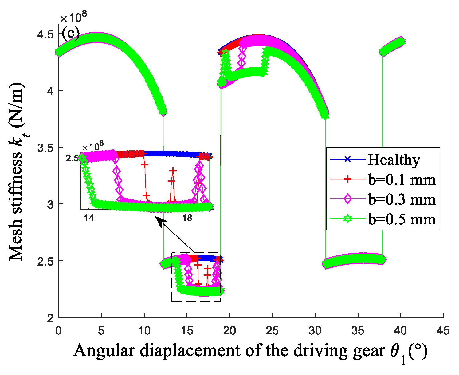
3.4. The Effect of Tooth Pitting on TVMS

For the driving gear of standard involute spur gears, the basic parameters are shown in Table 2. The distance from the base circle to the pitch line is
u = m z 1 2 m z 1 cos α 0 2 = 1.9   mm
The size of an elliptic cylinder can be selected as a = 0.5   mm , b = 0.3   mm and δ = 1   mm . The minimum and maximum horizontal distances between the base circle and the meshing point are 0.08   mm and 5.1   mm , respectively, and the corresponding angular displacements of the driving gear are θ 1 = 0 and θ 1 = 31.17 . The detailed contact and distribution information of severe pitting on gear tooth is plotted in Figure 4. Figure 5 illustrates the mesh stiffness of healthy gear and different degrees of pitting gears.
Combined with Figure 4 and Figure 5, the faulty gear tooth comes into meshing starting on line c 1 , which is 0.08   mm away from the base circle. The meshing point reaches the pitting area on the pitch line on line c 2 , where θ 1 = 15.01 and the distance between base circle to meshing point is 1.6   ( 0.08 + 1.52 )   mm . At this moment, effective contact width begins to decrease, resulting in the TVMS of the gear with three pitting damage levels being lower than that of the normal gear. For θ 1 ( 15.01 ,   18.51 ) , the reduction of TVMS decreases first and then increases because the reductions of tooth width, area, and area moment of inertia of the tooth section decrease at the beginning and then increase with the increase θ 1 . The reason why the reduction of TVMS of gear with moderate pitting is consistent with that of severe pitting is that the number and size of the two kinds of pitting faults on the pitch line are the same between 15.01 and 18.51 . However, in this interval, the reduction of TVMS of gear with slight pitting is less than that of moderate and severe pitting because the number of slight pitting is half less than that of the other two. On line c 3 and θ 1 = 18.51 , the engagement of pits on the pitch line is complete, and that of on the addendum begin to meshing. As the boundary between the pits on the pitch line and the pits on the addendum, there is no pitting on line c 3 . For θ 1 ( 18.51 ° , 21.54 ° ) , only severe pitting occurs, resulting in a significant reduction of TVMS. At the same time, the TVMS of slight and moderate pitting decreases slightly. In particular, no pitting in the tooth surface for θ 1 ( 0 ,   15.01 ] [ 21.54 ,   31.17 ] and θ 1 = 18.51 , where the TVMS is almost the same as that of gear without failure.
For three pitting damage levels, the influence of the size of pitting on TVMS could be studied when the position and number of tooth pitting are fixed. The TVMS evolution with different a is plotted in Figure 6 when b = 0.3   mm and δ = 1   mm , and the result for different b when a = 0.5   mm and δ = 1   mm is presented in Figure 7. From Figure 6, it could be found that the greater a , the greater the reduction of effective contact tooth width and TVMS, since the change of a only affects the size of pitting in the direction of tooth width. On the contrary, Figure 7 indicates the change of b only affects the pitting size from the base circle to the top land, while the size of pitting along the tooth width direction does not change. Therefore, in the pitting area, the reduction of TVMS caused by the same fault degrees does not change with the change of b .

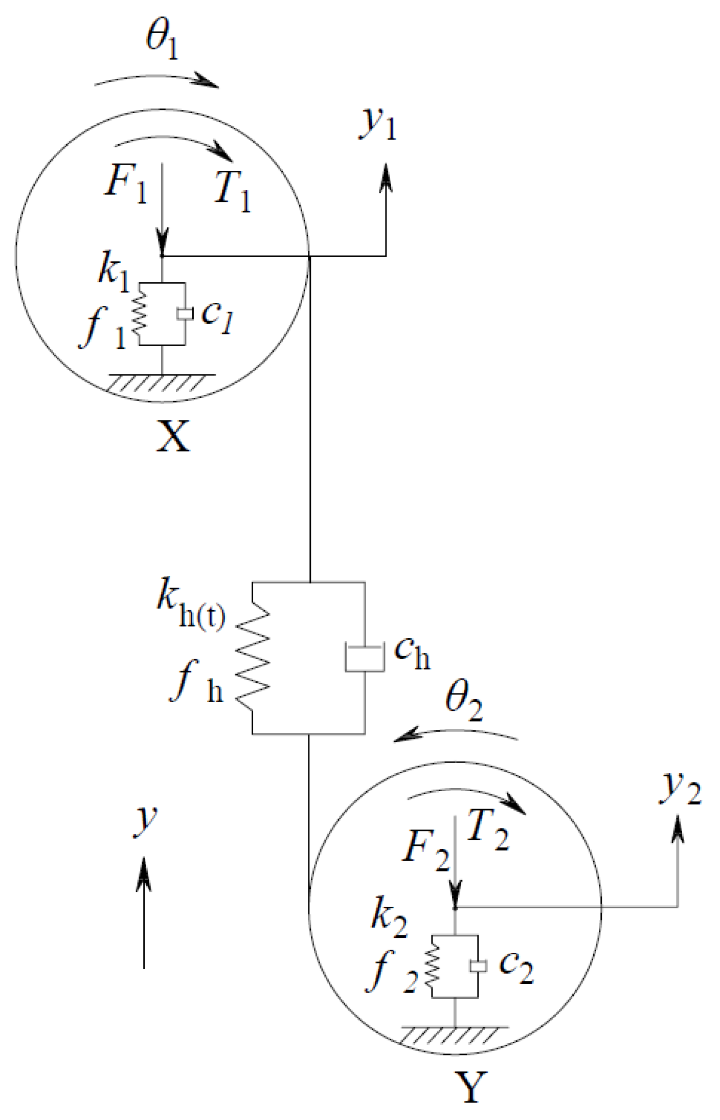
4. Dynamic Response of the Spur Gear Reducer in the Presence of Pitting

4.1. Numerical Simulation

In this section, we investigate the vibration response of a single-stage spur gear reducer with different levels of tooth pitting. A four-degree-of-freedom model is taken into consideration, including two angular motions θ 1 and θ 2 , and two lateral motions y 1 and y 2 , as shown in Figure 8. X and Y correspond to driving gear and driven gear. m i , I i , R b i , and T i express the mass, moment of inertia, base circle radius, and torque, respectively. c i , k i , and F i denote the equivalent damping, stiffness of the support bearing, and the vertical force of the support bearing, respectively. f i is the nonlinear clearance function of the supporting system. i = 1 represents gear X , and i = 2 represents gear Y . e is the transmission error, f h denotes the function related to the tooth backlash, and k h ( t ) refers to TVMS in healthy and defected cases. The motion equation can be expressed as [42]
{ I 1 d 2 θ 1 d t 2 = W d R b 1 + T 1 I 2 d 2 θ 2 d t 2 = W d R b 1 T 2 m 1 d 2 y 1 d t 2 + c 1 d y 1 d t + k 1 f 1 ( y 1 ) = F 1 W d m 2 d 2 y 2 d t 2 + c 2 d y 2 d t + k 2 f 2 ( y 2 ) = F 2 + W d ,
where
W d = c h ( R b 1 d θ 1 d t + R b 2 d θ 2 d t + d y 1 d t d y 2 d t d e d t ) + k h ( t ) f h ( R b 1 θ 1 + R b 2 θ 2 + y 1 y 2 e ) ,
e = F cos ( ω h t + φ h ) ,
Substitution of y 3 = R b 1 θ 1 + R b 2 θ 2 + y 1 y 2 e , m e = I 1 I 2 R b 1 2 I 2 R b 2 2 I 1 and F m = T 1 R b 1 = T 2 R b 2 into Equation (43) yields
{ m 1 d 2 y 1 d t 2 + c 1 d y 1 d t + k 1 f 1 ( y 1 ) + c h d y 3 d t + k h ( t ) f h ( y 3 ) = F 1 m 2 d 2 y 2 d t 2 + c 2 d y 2 d t + k 2 f 2 ( y 2 ) c h d y 3 d t k h ( t ) f h ( y 3 ) = F 2 m e d 2 y 3 d t 2 + c h d y 3 d t + k h ( t ) f h ( y 3 ) m e d 2 y 1 d t 2 + m e d 2 y 2 d t 2 + m e d 2 e d t 2 = F m ,
where f 1 ( y 1 ) = { y 1 d 1 , y 1 > d 1 0 , | y 1 | d 1 y 1 + d 1 , y 1 < d 1 , f 2 ( y 2 ) = { y 2 d 2 , y 2 > d 2 0 , | y 2 | d 2 y 2 + d 2 ,   y 2 < d 2 , f h ( y 3 ) = { y 3 d 3 , y 3 > d 3 0 , | y 3 | d 3 y 3 + d 3 , y 3 < d 3 , where d 3 denotes half of the tooth backlash; d 1 and d 2 are half of the clearance of the support bearing of driving gear and driven gear, respectively.
Figure 9a–d shows the DFT (discrete Fourier transform) spectrums about y 3 for healthy and defected cases, aiming at analyzing the features of TVMS with tooth pitting in the frequency domain. The system parameters are given in Table 2, the sampling frequency is f ¯ s = 1 × 10 5   Hz , and the rotational frequency of the driving gear shaft is fixed at f ¯ n 1 = 25   Hz . The larger version from 0   Hz to 6000   Hz is displayed in Figure 9.
Figure 9a shows the case for healthy gear is characterized by the dominance of the gear mesh frequency f ¯ m = 475   Hz and its frequency doubling n f ¯ m ( n = 2 , 3 ) . From Figure 9b–d, it could be found that a complex sideband structure appears around the gear mesh frequency and its frequency doubles, and as the level of faults increases, the amplitude of sidebands is increasingly obvious (the specific values are shown in Table 3).

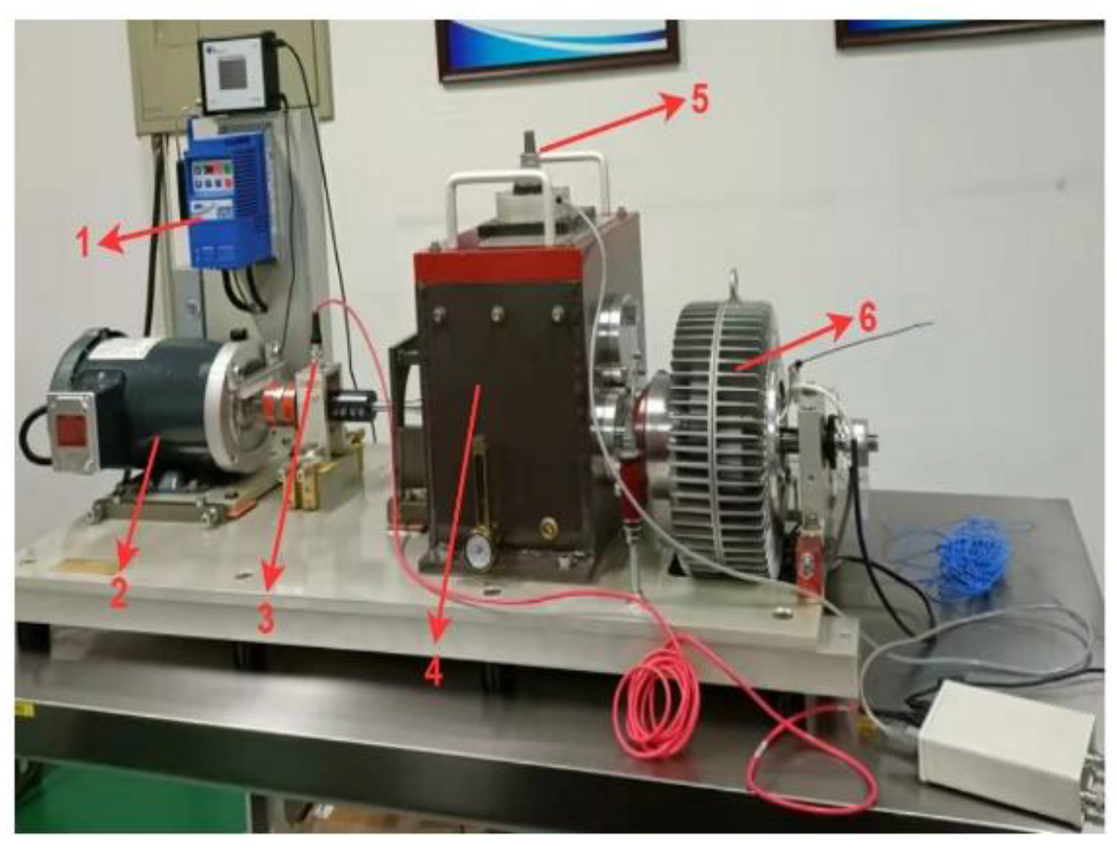
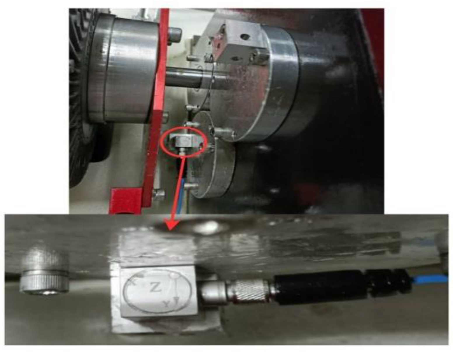
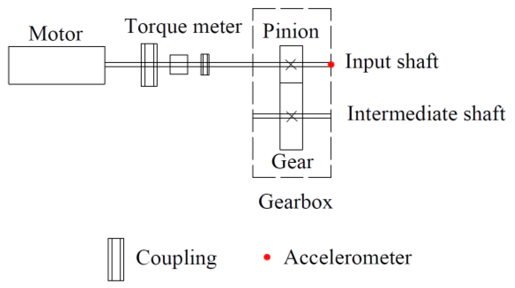
4.2. Experimental Study

The test rig experiments were carried out, and the experimental results are presented in this section. The test rig of the gear transmission system, which contains a one-stage fixed-axis gear, is presented in Figure 10. The location and direction of the piezoelectric acceleration sensor are shown in Figure 11, in which the sensitivity of lateral, longitudinal, and vertical directions ( X , Y , and Z ) is 2.56   mv / ms 2 , 2.50   mv / ms 2 , and 2.61   mv / ms 2 , respectively, and the range of the acceleration sensor is limited from 200   g to 200   g . Figure 12 is the sketch map of the single-stage fixed-axis spur gear reducer, where the number of teeth of the driving gear is z 1 = 18 , and that of the driven is z 2 = 47 . The DASP intelligent data acquisition instrument developed by the China Orient Institute of Noise and Vibration is adopted (see Figure 13).
The driving gears with different levels of tooth pitting damages generated by electrical discharge machining are shown in Figure 14 ( a = 2   mm , b = 1.5   mm , δ = 1   mm ). The details of three pitting damage levels are as follows: (1) slight pitting: a union of three elliptic cylinders centered on the tooth pitch line, where the total length of the pitting area along the tooth width is 8   mm , the maximum length along the tooth profile direction is 3   mm , and the height is 1   mm ; (2) moderate pitting: a union of six elliptic cylinders centered on the tooth pitch line, where the height of the pitting area and the maximum length along the tooth profile direction are the same as those of slight pitting, and the total length of the pitting area along the tooth width is 14   mm ; (3) severe pitting: except for union of six elliptic cylinders centered on the tooth pitch line, there is also a union of six elliptic cylinders centered on the tooth addendum, where the total length of the pitting area along the tooth width is 14   mm , the maximum length along the tooth profile direction is 6   mm and the height is 1   mm . In Figure 15, the detailed comparisons of the responses in the frequency domain for different pitting damage levels are illustrated, where the radial load of the bearing of the driven gear is 600   N , the frequency of the input shaft is selected as f n 1 = 25   Hz , and the sampling frequency and sampling time are 51.2   kHz and 10   s , respectively. The amplitudes of i f m and i f m ± f n 1   ( i = 1 ,   2 ,   3 ) are presented in Table 4, in which f m is gear mesh frequency. In the amplitude-frequency diagram of the normal gear, the mesh frequency and its frequency-doubling play a dominant role; at the same time, their non-obvious sidebands exist. As for the tooth pitting, a large number of sidebands appear near the gear mesh frequency and its harmonics, where the sidebands are separated by the rotation frequency of the input shaft. The more serious the degree of damage of the pitting, the more obvious degree of frequency modulation and the amplitudes of i f m , i f m ± f n 1 . Those results are consistent with some conclusions in [43,44]. Due to the complexity of experimental conditions, it is inevitable to be affected by external interference, so there are some deviations in the experiment, but most of the rules are effective.

5. Conclusions

In this paper, in order to find a more realistic tooth pitting model, a novel model is proposed considering the misalignment between the base circle and root circle. Under the influence of the pitting, the variation of TVMS with θ 1 is calculated. The amplitude-frequency responses of gear systems with different levels of tooth pitting damages are discussed theoretically and experimentally. The main conclusions can be summarized as:
(1)
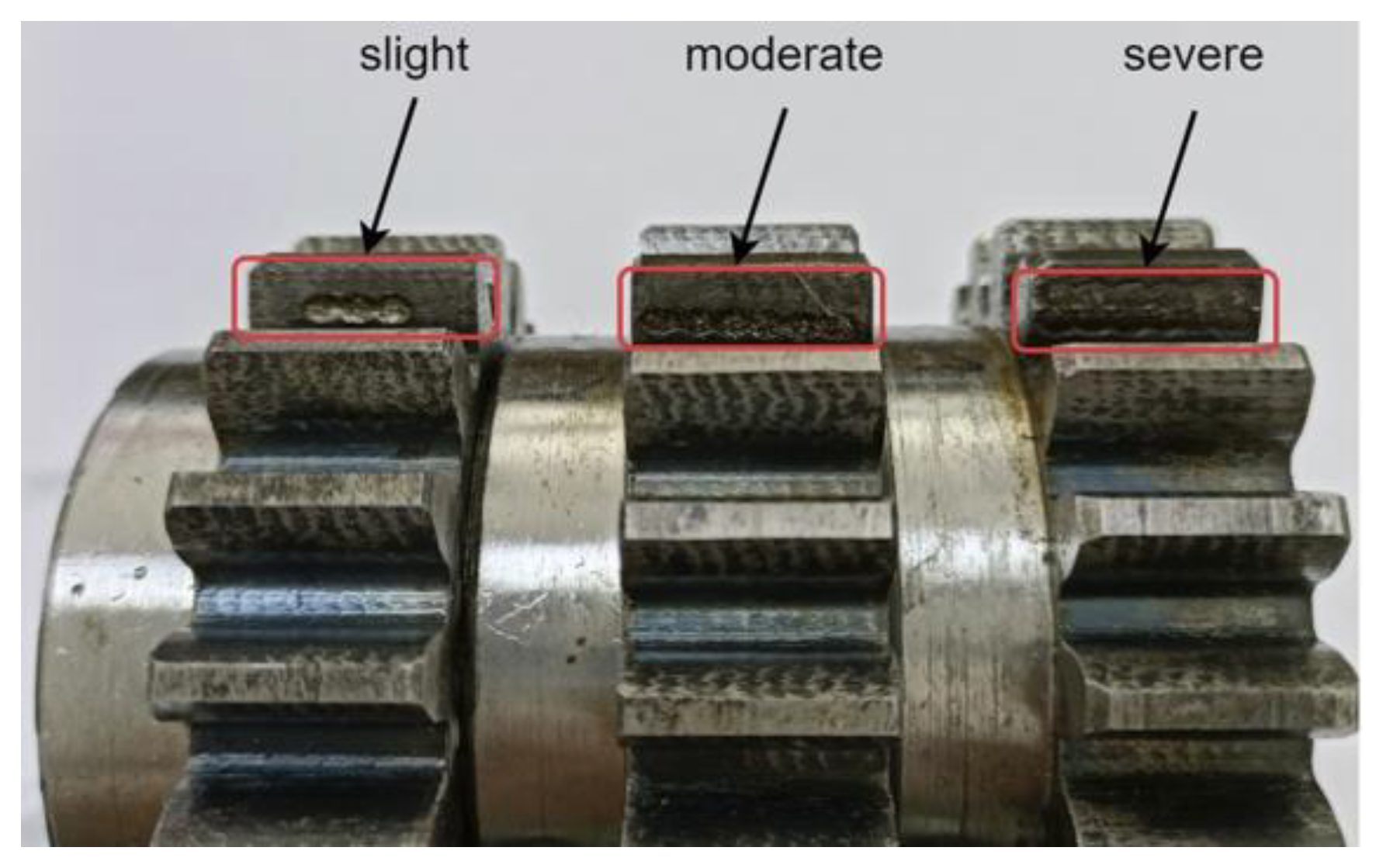
The overlap between different pitting is considered. The slight pitting model is established as the union of nine elliptic cylinders centered on the tooth pitch line. The moderate pitting is the union of 18 elliptic cylinders. The case for severe pitting, in addition to the union of 18 elliptic cylinders centered on the tooth pitch line, also includes the union of 18 elliptic cylinders centered on the tooth addendum. The new pitting model overcomes the problem of ignoring the overlap between different pits and is more consistent with the actual situation.
(2)
The presence of tooth pitting reduces the TVMS, and the more serious the pitting is, the more the TVMS decreases. The increase of the length of the major axis reduces the effective contact tooth width and eventually leads to the increase of the reduction of TVMS. The size of pitting perpendicular to the tooth width increases due to the increase of the length of the minor axis, which causes the increase of the region width of the reduction of TVMS.
(3)
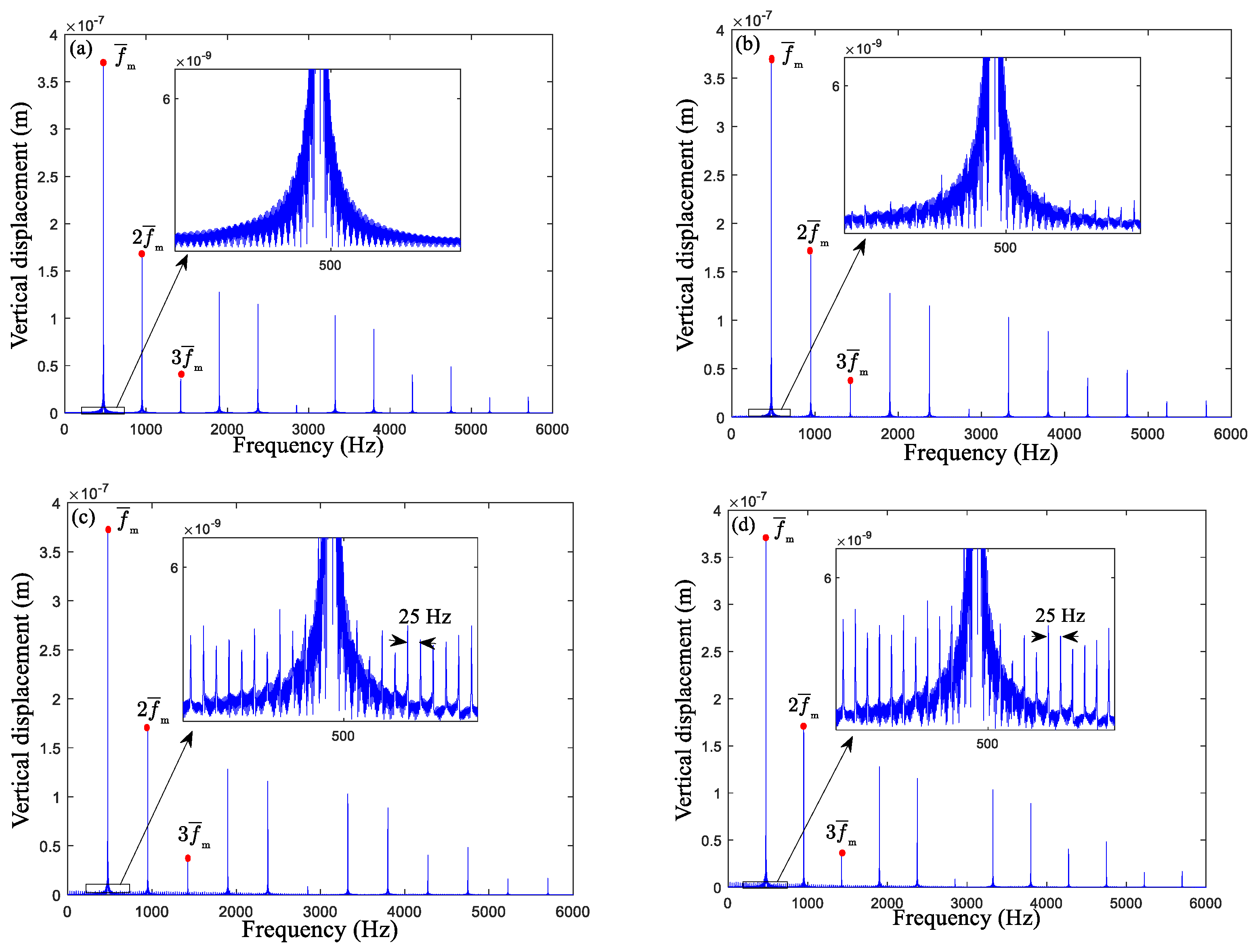
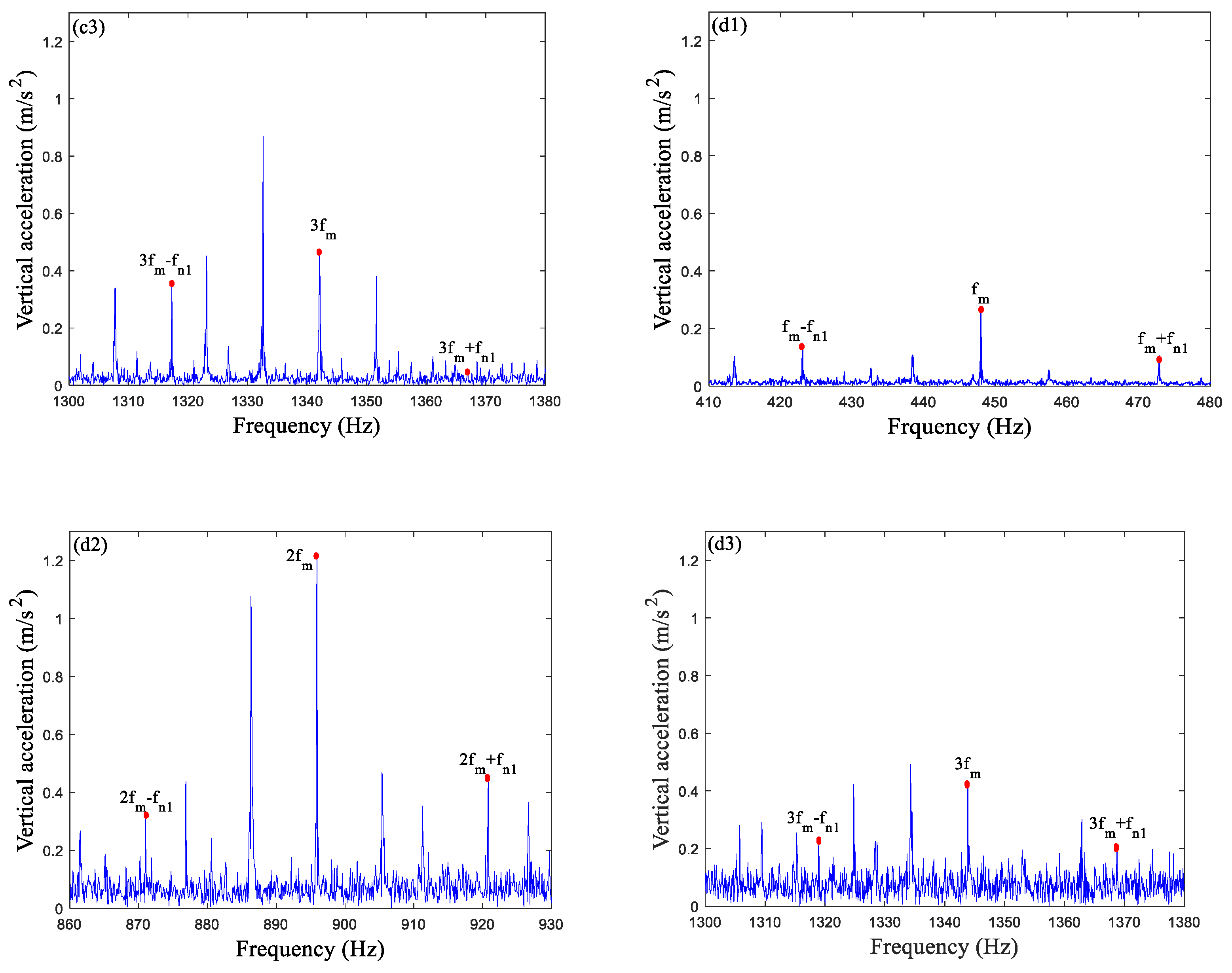
For a single-stage spur gear reducer with different levels of tooth pitting, the simulation results show that the complex sidebands appear near the gear mesh frequency and its harmonics, and their amplitudes increase with the increase of tooth pitting severity. The experimental signals with tooth pitting also show obvious fault feature, which qualitatively verifies the correctness of the simulation results.

Author Contributions

Conceptualization, J.H.; Funding acquisition, S.Y.; Methodology, J.H. and S.Y.; Supervision, Q.L. and Y.L.; Visualization, Q.L. and Y.L.; Writing—original draft, J.H.; Writing—review and editing, S.Y., Q.L. and Y.L. All authors have read and agreed to the published version of the manuscript.

Funding

The present work is supported by the National Natural Science Foundation of China (Nos. 11790282, 12032017, 11802184, 11902205, and 12002221), S&T Program of Hebei (20310803D), and Natural Science Foundation of Hebei Province (No A2020210028).

Institutional Review Board Statement

Not applicable.

Informed Consent Statement

Not applicable.

Data Availability Statement

Not applicable.

Conflicts of Interest

The authors declare no conflict of interest.

Nomenclature

z 1 Number of teeth of driving gear
z 2 Number of teeth of driven gear
R b Base radius
R f Root radius
θ d Angular displacement of the driving gear in the double-tooth engagement region
θ 1 Angular displacement of the driving gear
G Shear modulus
u Distance from the base circle to the pitch line
h Distance between the contact point and the gear center line
F Contact force
( x 0 , z 0 ) Center of the transition curve of driving gear
ρ Radius of the transition curve of driving gear
d Distance from the contact point to the base circle
h x Height of the section of which the distance to the base circle is x
h x 1 Height of the section of which the distance to the base circle is x 1
I x Area moment of inertia of the section of gear without fault, where the distance to the base circle is x
I x 1 Area moment of inertia of the section of gear without fault, where the distance to the base circle is x 1
A x Area of the section of gear without fault, where the distance to the base circle is x
A x 1 Area of the section of gear without fault, where the distance to the base circle is x 1
Δ L pit i   ( i = 1 ,   2 ,   3 ,   4 ) Reduction of tooth width for Case i   ( i = 1 ,   2 ,   3 ,   4 )
Δ A x _ pit i   ( i = 1 ,   2 ,   3 ,   4 ) Reduction of area of inertia of the tooth section for Case i   ( i = 1 ,   2 ,   3 ,   4 )
Δ I x _ pit i   ( i = 1 ,   2 ,   3 ,   4 ) Reduction of area moment of inertia of the tooth section for Case i   ( i = 1 ,   2 ,   3 ,   4 )
Δ L pit i   ( i = 5 ,   6 ) Reduction of tooth width for Case i   ( i = 7 ,   8 )
Δ A x _ pit i   ( i = 5 ,   6 ) Reduction of area of inertia of the tooth section for Case i   ( i = 7 ,   8 )
Δ I x _ pit i   ( i = 5 ,   6 ) Reduction of area moment of inertia of the tooth section for Case i   ( i = 7 ,   8 )

Appendix A

For slight pitting:
1 k h = { 4 ( 1 v 2 ) π E L ,   0 x < u b   o r   x u b 4 ( 1 v 2 ) π E ( L Δ L pit 1 ) ,   u b < x < u 3 2 b   o r   u + 3 2 b x < u + b 4 ( 1 v 2 ) π E ( L Δ L pit 2 ) ,   u 3 2 b x < u + 3 2 b ,
1 k b = { A ¯ 1 + 2 F 2 0 d [ F b ( d x ) F a h ] 2 2 E I x d x ,   0 x < u b A ¯ 2 + 2 F 2 u b d [ F b ( d x ) F a h ] 2 2 E ( I x Δ I x _ pit 1 ) d x ,   u b x < u 3 2 b A ¯ 3 + 2 F 2 u 3 2 b d [ F b ( d x ) F a h ] 2 2 E ( I x Δ I x _ pit 2 ) d x ,   u 3 2 b x < u + 3 2 b A ¯ 4 + 2 F 2 u + 3 2 b d [ F b ( d x ) F a h ] 2 2 E ( I x Δ I x _ pit 1 ) d x ,   u + 3 2 b x < u + b A ¯ 5 + 2 F 2 u + b d [ F b ( d x ) F a h ] 2 2 E I x d x ,   x u + b ,
1 k s = { B ¯ 1 + 2 F 2 0 d 1.2 F b 2 2 G A x d x ,   0 x < u b B ¯ 2 + 2 F 2 u b d 1.2 F b 2 2 G ( A x Δ A x _ pit 1 ) d x ,   u b x < u 3 2 b B ¯ 3 + 2 F 2 u 3 2 b d 1.2 F b 2 2 G ( A x Δ A x _ pit 2 ) d x ,   u 3 2 b x < u + 3 2 b B ¯ 4 + 2 F 2 u + 3 2 b d 1.2 F b 2 2 G ( A x Δ A x _ pit 1 ) d x ,   u + 3 2 b x < u + b B ¯ 5 + 2 F 2 u + b d 1.2 F b 2 2 G A x d x ,   x   u + b ,
1 k a = { C ¯ 1 + 2 F 2 0 d F a 2 2 E A x d x ,   0 x < u b C ¯ 2 + 2 F 2 u b d F a 2 2 E ( A x Δ A x _ pit 1 ) d x ,   u b x < u 3 2 b C ¯ 3 + 2 F 2 u 3 2 b d F a 2 2 E ( A x Δ A x _ pit 2 ) d x ,   u 3 2 b x < u + 3 2 b C ¯ 4 + 2 F 2 u + 3 2 b d F a 2 2 E ( A x Δ A x _ pit 1 ) d x ,   u + 3 2 b x < u + b C ¯ 5 + 2 F 2 u + b d F a 2 2 E A x d x ,   x u + b ,
where
A ¯ 1 = 2 F 2 0 x b x r [ F b ( d + x 1 ) F a h ] 2 2 E I x 1 d x 1 ,
A ¯ 2 = A ¯ 1 + 2 F 2 0 u b [ F b ( d x ) F a h ] 2 2 E I x d x ,
A ¯ 3 = A ¯ 2 + 2 F 2 u b u 3 2 b [ F b ( d x ) F a h ] 2 2 E ( I x Δ I x _ pit 1 ) d x ,
A ¯ 4 = A ¯ 3 + 2 F 2 u 3 2 b u + 3 2 b [ F b ( d x ) F a h ] 2 2 E ( I x Δ I x _ pit 2 ) d x ,
A ¯ 5 = A ¯ 4 + 2 F 2 u + 3 2 b u + b [ F b ( d x ) F a h ] 2 2 E ( I x Δ I x _ pit 1 ) d x ,
B ¯ 1 = 2 F 2 0 x b x r 1.2 F b 2 2 G A x 1 d x 1 ,
B ¯ 2 = B ¯ 1 + 2 F 2 0 u b 1.2 F b 2 2 G A x d x ,
B ¯ 3 = B ¯ 2 + 2 F 2 u b u 3 2 b 1.2 F b 2 2 G ( A x Δ A x _ pit 1 ) d x ,
B ¯ 4 = B ¯ 3 + 2 F 2 u 3 2 b u + 3 2 b 1.2 F b 2 2 G ( A x Δ A x _ pit 2 ) d x ,
B ¯ 5 = B ¯ 4 + 2 F 2 u + 3 2 b u + b 1.2 F b 2 2 G ( A x Δ A x _ pit 1 ) d x ,
C ¯ 1 = 2 F 2 0 x b x r F a 2 2 E A x 1 d x 1 ,
C ¯ 2 = C ¯ 1 + 2 F 2 0 u b F a 2 2 E A x d x ,
C ¯ 3 = C ¯ 2 + 2 F 2 u b u 3 2 b F a 2 2 E ( A x Δ A x _ pit 1 ) d x ,
C ¯ 4 = C ¯ 3 + 2 F 2 u 3 2 b u + 3 2 b F a 2 2 E ( A x Δ A x _ pit 2 ) d x ,
C ¯ 5 = C ¯ 4 + 2 F 2 u + 3 2 b u + b F a 2 2 E ( A x Δ A x _ pit 1 ) d x .
For moderate pitting:
1 k h = { 4 ( 1 v 2 ) π E L ,   0 x < u b   o r   x u b 4 ( 1 v 2 ) π E ( L Δ L pit 3 ) ,   u b < x < u 3 2 b   o r   u + 3 2 b x < u + b 4 ( 1 v 2 ) π E ( L Δ L pit 4 ) ,   u 3 2 b x < u + 3 2 b ,
1 k b = { A ¯ 1 + 2 F 2 0 d [ F b ( d x ) F a h ] 2 2 E I x d x ,   0 x < u b A ¯ 2 + 2 F 2 u b d [ F b ( d x ) F a h ] 2 2 E ( I x Δ I x _ pit 3 ) d x ,   u b x < u 3 2 b D ¯ 1 + 2 F 2 u 3 2 b d [ F b ( d x ) F a h ] 2 2 E ( I x Δ I x _ pit 4 ) d x ,   u 3 2 b x < u + 3 2 b D ¯ 2 + 2 F 2 u + 3 2 b d [ F b ( d x ) F a h ] 2 2 E ( I x Δ I x _ pit 3 ) d x ,   u + 3 2 b x < u + b D ¯ 3 + 2 F 2 u + b d [ F b ( d x ) F a h ] 2 2 E I x d x ,   x u + b ,
1 k s = { B ¯ 1 + 2 F 2 0 d 1.2 F b 2 2 G A x d x ,   0 x < u b B ¯ 2 + 2 F 2 u b d 1.2 F b 2 2 G ( A x Δ A x _ pit 3 ) d x ,   u b x < u 3 2 b E ¯ 1 + 2 F 2 u 3 2 b d 1.2 F b 2 2 G ( A x Δ A x _ pit 4 ) d x ,   u 3 2 b x < u + 3 2 b E ¯ 2 + 2 F 2 u + 3 2 b d 1.2 F b 2 2 G ( A x Δ A x _ pit 3 ) d x ,   u + 3 2 b x < u + b E ¯ 3 + 2 F 2 u + b d 1.2 F b 2 2 G A x d x ,   x   u + b ,
1 k a = { C ¯ 1 + 2 F 2 0 d F a 2 2 E A x d x ,   0 x < u b C ¯ 2 + 2 F 2 u b d F a 2 2 E ( A x Δ A x _ pit 3 ) d x ,   u b x < u 3 2 b F ¯ 1 + 2 F 2 u 3 2 b d F a 2 2 E ( A x Δ A x _ pit 4 ) d x ,   u 3 2 b x < u + 3 2 b F ¯ 2 + 2 F 2 u + 3 2 b d F a 2 2 E ( A x Δ A x _ pit 3 ) d x ,   u + 3 2 b x < u + b F ¯ 3 + 2 F 2 u + b d F a 2 2 E A x d x ,   x u + b ,
where
D ¯ 1 = A ¯ 2 + 2 F 2 u b u 3 2 b [ F b ( d x ) F a h ] 2 2 E ( I x Δ I x _ pit 3 ) d x ,
D ¯ 2 = D ¯ 1 + 2 F 2 u 3 2 b u + 3 2 b [ F b ( d x ) F a h ] 2 2 E ( I x Δ I x _ pit 4 ) d x ,
D ¯ 3 = D ¯ 2 + 2 F 2 u + 3 2 b u + b [ F b ( d x ) F a h ] 2 2 E ( I x Δ I x _ pit 3 ) d x ,
E ¯ 1 = B ¯ 2 + 2 F 2 u b u 3 2 b 1.2 F b 2 2 G ( A x Δ A x _ pit 3 ) d x ,
E ¯ 2 = E ¯ 1 + 2 F 2 u 3 2 b u + 3 2 b 1.2 F b 2 2 G ( A x Δ A x _ pit 4 ) d x ,
E ¯ 3 = E ¯ 2 + 2 F 2 u + 3 2 b u + b 1.2 F b 2 2 G ( A x Δ A x _ pit 3 ) d x ,
F ¯ 1 = C ¯ 2 + 2 F 2 u b u 3 2 b F a 2 2 E ( A x Δ A x _ pit 3 ) d x ,
F ¯ 2 = F ¯ 1 + 2 F 2 u 3 2 b u + 3 2 b F a 2 2 E ( A x Δ A x _ pit 4 ) d x ,
F ¯ 3 = F ¯ 2 + 2 F 2 u + 3 2 b u + b F a 2 2 E ( A x Δ A x _ pit 3 ) d x .
For severe pitting:
1 k h = { 4 ( 1 v 2 ) π E L , 0 x < u b   o r   x u + 3 b 4 ( 1 v 2 ) π E ( L Δ L pit 3 ) , u b < x < u 3 2 b   o r   u + 3 2 b x < u + b 4 ( 1 v 2 ) π E ( L Δ L pit 4 ) , u 3 2 b x < u + 3 2 b   4 ( 1 v 2 ) π E ( L Δ L pit 5 ) ,   u + b x < ( u + 2 b ) 3 2 b   o r   ( u + 2 b ) 3 2 b x < u + 3 b 4 ( 1 v 2 ) π E ( L Δ L pit 6 ) ,   ( u + 2 b ) 3 2 b x < ( u + 2 b ) + 3 2 b ,
1 k b = { A ¯ 1 + 2 F 2 0 d [ F b ( d x ) F a h ] 2 2 E I x d x ,   0 x < u b A ¯ 2 + 2 F 2 u b d [ F b ( d x ) F a h ] 2 2 E ( I x Δ I x _ pit 3 ) d x ,   u b x < u 3 2 b D ¯ 1 + 2 F 2 u 3 2 b d [ F b ( d x ) F a h ] 2 2 E ( I x Δ I x _ pit 4 ) d x ,   u 3 2 b x < u + 3 2 b D ¯ 2 + 2 F 2 u + 3 2 b d [ F b ( d x ) F a h ] 2 2 E ( I x Δ I x _ pit 3 ) d x ,   u + 3 2 b x < u + b D ¯ 3 + 2 F 2 u + b d [ F b ( d x ) F a h ] 2 2 E ( I x Δ I x _ pit 5 ) d x ,   u + b x < ( u + 2 b ) 3 2 b G ¯ 1 + 2 F 2 ( u + 2 b ) 3 2 b d [ F b ( d x ) F a h ] 2 2 E ( I x Δ I x _ pit 6 ) d x ,   ( u + 2 b ) 3 2 b x < ( u + 2 b ) + 3 2 b G ¯ 2 + 2 F 2 ( u + 2 b ) + 3 2 b d [ F b ( d x ) F a h ] 2 2 E ( I x Δ I x _ pit 5 ) d x ,   ( u + 2 b ) + 3 2 b x < ( u + 2 b ) + b G ¯ 3 + 2 F 2 u + 3 b d [ F b ( d x ) F a h ] 2 2 E I x d x ,   x ( u + 2 b ) + b ,
1 k s = { B ¯ 1 + 2 F 2 0 d 1.2 F b 2 2 G A x d x ,   0 x < u b B ¯ 2 + 2 F 2 u b d 1.2 F b 2 2 G ( A x Δ A x _ pit 3 ) d x ,   u b x < u 3 2 b E ¯ 1 + 2 F 2 u 3 2 b d 1.2 F b 2 2 G ( A x Δ A x _ pit 4 ) d x ,   u 3 2 b x < u + 3 2 b E ¯ 2 + 2 F 2 u + 3 2 b d 1.2 F b 2 2 G ( A x Δ A x _ pit 3 ) d x ,   u + 3 2 b x < u + b E ¯ 3 + 2 F 2 u + b d 1.2 F b 2 2 G ( A x Δ A x _ pit 5 ) d x ,   u + b x < ( u + 2 b ) 3 2 b H ¯ 1 + 2 F 2 ( u + 2 b ) 3 2 b d 1.2 F b 2 2 G ( A x Δ A x _ pit 6 ) d x ,   ( u + 2 b ) 3 2 b x < ( u + 2 b ) + 3 2 b H ¯ 2 + 2 F 2 ( u + 2 b ) + 3 2 b d 1.2 F b 2 2 G ( A x Δ A x _ pit 5 ) d x ,   ( u + 2 b ) + 3 2 b x < ( u + 2 b ) + b H ¯ 3 + 2 F 2 u + 3 b d 1.2 F b 2 2 G A x d x , x ( u + 2 b ) + b
1 k a = { C ¯ 1 + 2 F 2 0 d F a 2 2 E A x d x ,   0 x < u b C ¯ 2 + 2 F 2 u b d F a 2 2 E ( A x Δ A x _ pit 3 ) d x ,   u b x < u 3 2 b F ¯ 1 + 2 F 2 u 3 2 b d F a 2 2 E ( A x Δ A x _ pit 4 ) d x ,   u 3 2 b x < u + 3 2 b F ¯ 2 + 2 F 2 u + 3 2 b d F a 2 2 E ( A x Δ A x _ pit 3 ) d x ,   u + 3 2 b x < u + b F ¯ 3 + 2 F 2 u + b d F a 2 2 E ( A x Δ A x _ pit 5 ) d x ,   u + b x < ( u + 2 b ) 3 2 b I ¯ 1 + 2 F 2 ( u + 2 b ) 3 2 b d F a 2 2 E ( A x Δ A x _ pit 6 ) d x ,   ( u + 2 b ) 3 2 b x < ( u + 2 b ) + 3 2 b I ¯ 2 + 2 F 2 ( u + 2 b ) + 3 2 b d F a 2 2 E ( A x Δ A x _ pit 5 ) d x ,   ( u + 2 b ) + 3 2 b x < ( u + 2 b ) + b I ¯ 3 + 2 F 2 u + 3 b d F a 2 2 E A x d x ,   x ( u + 2 b ) + b ,
where
G ¯ 1 = D ¯ 3 + 2 F 2 u + b ( u + 2 b ) 3 2 b [ F b ( d x ) F a h ] 2 2 E ( I x Δ I x _ pit 5 ) d x ,
G ¯ 2 = G ¯ 1 + 2 F 2 ( u + 2 b ) 3 2 b ( u + 2 b ) + 3 2 b [ F b ( d x ) F a h ] 2 2 E ( I x Δ I x _ pit 6 ) d x ,
G ¯ 3 = G ¯ 2 + 2 F 2 ( u + 2 b ) + 3 2 b u + 3 b [ F b ( d x ) F a h ] 2 2 E ( I x Δ I x _ pit 5 ) d x ,
H ¯ 1 = E ¯ 3 + 2 F 2 u + b ( u + 2 b ) 3 2 b 1.2 F b 2 2 G ( A x Δ A x _ pit 5 ) d x ,
H ¯ 2 = H ¯ 1 + 2 F 2 ( u + 2 b ) 3 2 b ( u + 2 b ) + 3 2 b 1.2 F b 2 2 G ( A x Δ A x _ pit 6 ) d x ,
H ¯ 3 = H ¯ 2 + 2 F 2 ( u + 2 b ) + 3 2 b u + 3 b 1.2 F b 2 2 G ( A x Δ A x _ pit 5 ) d x ,
I ¯ 1 = F ¯ 3 + 2 F 2 u + b ( u + 2 b ) 3 2 b F a 2 2 E ( A x Δ A x _ pit 5 ) d x ,
I ¯ 2 = I ¯ 1 + 2 F 2 ( u + 2 b ) 3 2 b ( u + 2 b ) + 3 2 b F a 2 2 E ( A x Δ A x _ pit 6 ) d x ,
I ¯ 3 = I ¯ 2 + 2 F 2 ( u + 2 b ) + 3 2 b u + 3 b F a 2 2 E ( A x Δ A x _ pit 5 ) d x .

References

  1. Wei, S.; Chu, F.L.; Ding, H.; Chen, L.Q. Dynamic analysis of uncertain spur gear systems. Mech. Syst. Signal Process. 2021, 150, 107280. [Google Scholar] [CrossRef]
  2. Jiang, J.Z.; Chen, Z.G.; Zhai, W.M.; Zhang, T.; Li, Y.F. Vibration characteristics of railway locomotive induced by gear tooth root crack fault under transient conditions. Eng. Fail. Anal. 2019, 108, 104285. [Google Scholar] [CrossRef]
  3. Chen, Z.G.; Zhai, W.M.; Wang, K.Y. Dynamic investigation of a locomotive with effect of gear transmissions under tractive conditions. J. Sound Vib. 2017, 408, 220–233. [Google Scholar] [CrossRef]
  4. Yang, L.; Yang, S.P.; Yang, Y.T. Dynamic behavior of a locomotive nonlinear rotor system. J. Vib. Shock 2018, 37, 33–42. [Google Scholar] [CrossRef]
  5. Liu, Y.H.; Shi, Z.Q.; Shen, G.J.; Zhen, D.; Wang, F.Y. Evaluation model of mesh stiffness for spur gear with tooth tip chipping fault. Mech. Mach. Theory 2021, 158, 104238. [Google Scholar] [CrossRef]
  6. Chen, Z.G.; Shao, Y.M. Mesh stiffness calculation of a spur gear pair with tooth profile modification and tooth root crack. Mech. Mach. Theory 2013, 62, 63–74. [Google Scholar] [CrossRef]
  7. Yang, S.P.; Liu, Y.Q. Development of railway vehicle dynamics and control. J. Dyn. Control. 2020, 18, 1–4. [Google Scholar] [CrossRef]
  8. Qin, Y.; Mao, Y.F.; Tang, B.P.; Wang, Y.; Chen, H.Z. M-band flexible wavelet transform and its application to the fault diagnosis of planetary gear transmission systems. Mech. Syst. Signal Process. 2019, 134, 106298.1–106298.26. [Google Scholar] [CrossRef]
  9. Feng, K.; Smith, W.A.; Randall, R.B.; Wu, H.K.; Peng, Z.X. Vibration-based monitoring and prediction of surface profile change and pitting density in a spur gear wear process. Mech. Syst. Signal Process. 2022, 165, 108319. [Google Scholar] [CrossRef]
  10. Jia, S.X.; Howard, I. Comparison of localised spalling and crack damage from dynamic modelling of spur gear vibrations. Mech. Syst. Signal Process. 2006, 20, 332–349. [Google Scholar] [CrossRef]
  11. Cooley, C.G.; Parker, R.G.; Vijayakar, S.M. A frequency domain finite element approach for three-dimensional gear dynamics. J. Vib. Acoust. 2011, 133, 041004. [Google Scholar] [CrossRef]
  12. Rincon, A.F.; Viadero, F.; Iglesias, M.; de-Juan, A.; Garcia, P.; Sancibrian, R. Effect of cracks and pitting defects on gear meshing. Proc. Inst. Mech. Eng. Part C J. Mech. Eng. Sci. 2012, 226, 2805–2815. [Google Scholar] [CrossRef]
  13. Yang, D.C.H.; Lin, J.Y. Hertzian damping, tooth friction and bending elasticity in gear impact dynamics. J. Mech. Transm. Autom. Des. 1987, 109, 189–196. [Google Scholar] [CrossRef]
  14. Tian, X.H. Dynamic Simulation for System Response of Gearbox Including Localized Gear Faults. Ph.D. Thesis, University of Alberta, Edmonton, AB, Canada, 2004. [Google Scholar]
  15. Sainsot, P.; Velex, P.; Duverger, O. Contribution of gear body to tooth deflections-a new bidimensional analytical formula. J. Mech. Des. 2004, 126, 748–752. [Google Scholar] [CrossRef]
  16. Sánchez, M.B.; Pleguezuelos, M.; Pedrero, J.I. Approximate equations for the meshing stiffness and the load sharing ratio of spur gears including hertzian effects. Mech. Mach. Theory 2017, 109, 231–249. [Google Scholar] [CrossRef]
  17. Xiong, Y.S.; Huang, K.; Xu, F.W.; Yi, Y.; Sang, M.; Zhai, H. Research on the influence of backlash on mesh stiffness and the nonlinear dynamics of spur gears. Appl. Sci. 2019, 9, 1029. [Google Scholar] [CrossRef] [Green Version]
  18. Del Rincon, A.F.; Viadero, F.; Iglesias, M.; Garcia, P.; De-Juan, A.; Sancibrian, R. A model for the study of meshing stiffness in spur gear transmissions. Mech. Mach. Theory 2013, 61, 30–58. [Google Scholar] [CrossRef]
  19. Ma, H.; Pang, X.; Zeng, J.; Wang, Q.B.; Wen, B.C. Effects of gear crack propagation paths on vibration responses of the perforated gear system. Mech. Syst. Signal Process. 2015, 62–63, 113–128. [Google Scholar] [CrossRef]
  20. Wu, S.Y.; Zuo, M.J.; Parey, A. Simulation of spur gear dynamics and estimation of fault growth. J. Sound Vib. 2008, 317, 608–624. [Google Scholar] [CrossRef]
  21. Liang, X.H.; Zuo, M.J.; Pandey, M. Analytically evaluating the influence of crack on the mesh stiffness of a planetary gear set. Mech. Mach. Theory 2014, 76, 20–38. [Google Scholar] [CrossRef]
  22. Jiang, F.; Ding, K.; He, G.L.; Sun, Y.L.; Wang, L.H. Vibration fault features of planetary gear train with cracks under time-varying flexible transfer functions. Mech. Mach. Theory 2021, 158, 104237. [Google Scholar] [CrossRef]
  23. Meng, Z. Vibration response and fault characteristics analysis of gear based on time-varying mesh stiffness. Mech. Mach. Theory 2020, 148, 103786. [Google Scholar] [CrossRef]
  24. Pandya, Y.; Parey, A. Experimental investigation of spur gear tooth mesh stiffness in the presence of crack using photoelasticity technique. Eng. Fail. Anal. 2013, 34, 488–500. [Google Scholar] [CrossRef]
  25. Chen, Z.G.; Shao, Y.M. Dynamic simulation of spur gear with tooth root crack propagating along tooth width and crack depth. Eng. Fail. Anal. 2011, 18, 2149–2164. [Google Scholar] [CrossRef]
  26. Chaari, F.; Baccar, W.; Abbes, M.S.; Haddar, M. Effect of spalling or tooth breakage on gearmesh stiffness and dynamic response of a one-stage spur gear transmission. Eur. J. Mech.-A/Solids 2008, 27, 691–705. [Google Scholar] [CrossRef]
  27. Abouel-seoud, S.A.; Dyab, E.S.; Elmorsy, M.S. Influence of tooth pitting and cracking on gear meshing stiffness and dynamic response of wind turbine gearbox. Int. J. Sci. Adv. Technol. 2012, 2, 151–165. [Google Scholar]
  28. Ma, H.; Li, Z.W.; Feng, M.J.; Feng, R.J.; Wen, B.C. Time-varying mesh stiffness calculation of spur gears with spalling defect. Eng. Fail. Anal. 2016, 66, 166–176. [Google Scholar] [CrossRef]
  29. Jiang, H.J.; Shao, Y.M.; Mechefske, C.K. Dynamic characteristics of helical gears under sliding friction with spalling defect. Eng. Fail. Anal. 2014, 39, 92–107. [Google Scholar] [CrossRef]
  30. Liang, X.H.; Liu, Z.L.; Pan, J.; Zuo, M.J. Spur gear tooth pitting propagation assessment using model-based analysis. Chin. J. Mech. Eng. 2017, 30, 1369–1382. [Google Scholar] [CrossRef] [Green Version]
  31. Liang, X.H.; Zhang, H.S.; Liu, L.B.; Zuo, M.J. The influence of tooth pitting on the mesh stiffness of a pair of external spur gears. Mech. Mach. Theory 2016, 106, 1–15. [Google Scholar] [CrossRef]
  32. Lei, Y.G.; Liu, Z.Y.; Wang, D.L.; Yang, X.; Liu, H.; Lin, J. A probability distribution model of tooth pits for evaluating time-varying mesh stiffness of pitting gears. Mech. Syst. Signal Process. 2018, 106, 355–366. [Google Scholar] [CrossRef]
  33. Chen, T.Y.; Wang, Y.X.; Chen, Z.G. A novel distribution model of multiple teeth pits for evaluating time-varying mesh stiffness of external spur gears. Mech. Syst. Signal Process. 2019, 129, 479–501. [Google Scholar] [CrossRef]
  34. Luo, Y.; Baddour, N.; Liang, M. Dynamical modeling and experimental validation for tooth pitting and spalling in spur gears. Mech. Syst. Signal Process. 2018, 119, 155–181. [Google Scholar] [CrossRef]
  35. Luo, Y.; Baddour, N.; Han, G.S.; Jiang, F.; Liang, M. Evaluation of the time-varying mesh stiffness for gears with tooth spalls with curved-bottom features. Eng. Fail. Anal. 2018, 92, 430–442. [Google Scholar] [CrossRef]
  36. Luo, Y.; Baddour, N.; Liang, M. A shape-independent approach to modelling gear tooth spalls for time varying mesh stiffness evaluation of a spur gear pair. Mech. Syst. Signal Process. 2019, 120, 836–852. [Google Scholar] [CrossRef]
  37. Meng, Z.; Wang, F.L.; Shi, G.X. A novel evolution model of pitting failure and effect on time-varying meshing stiffness of spur gears. Eng. Fail. Anal. 2021, 120, 105068. [Google Scholar] [CrossRef]
  38. Anderson, A.E. Friction, lubrication and wear technology. In ASM Handbook; ASM international: Almere, The Netherlands, 1992. [Google Scholar]
  39. Tan, C.K.; Irving, P.; Mba, D. A comparative experimental study on the diagnostic and prognostic capabilities of acoustics emission, vibration and spectrometric oil analysis for spur gears. Mech. Syst. Signal Process. 2007, 21, 208–233. [Google Scholar] [CrossRef] [Green Version]
  40. Feng, K.; Smith, W.A.; Borghesani, P.; Randall, R.B.; Peng, Z. Use of cyclostationary properties of vibration signals to identify gear wear mechanisms and track wear evolution. Mech. Syst. Signal Process. 2020, 150, 107258. [Google Scholar] [CrossRef]
  41. Wang, J.J. Calculation Method of Time-Varying Mesh Stiffness with Faults and Dynamic Modelling and Simulation of Gear System. Master’s Thesis, Shijiazhaung Tiedao University, Shijiazhuang, China, 2015. [Google Scholar]
  42. Hou, J.Y.; Yang, S.P.; Li, Q.; Liu, Y.Q.; Wang, J.J. Mesh stiffness calculation and vibration analysis of spur gear pair with tooth crack considering the misalignment between base circle and root circle. Int. J. Mech. Syst. Dyn. 2021, 1, 143–156. [Google Scholar] [CrossRef]
  43. Li, Y.Z.; Ding, K.; He, G.L.; Lin, H.B. Vibration mechanisms of spur gear pair in healthy and fault states. Mech. Syst. Signal Process. 2016, 81, 183–201. [Google Scholar] [CrossRef]
  44. Ma, R.; Chen, Y.S. Research on the dynamic mechanism of the gear system with local crack and spalling failure. Eng. Fail. Anal. 2012, 26, 12–20. [Google Scholar] [CrossRef]
Figure 1. Pitting distribution on gear teeth: (a) slight pitting; (b) zoomed-in picture of (a); (c) moderate pitting; (d) severe pitting.
Mathematics 10 00471 g001aMathematics 10 00471 g001b
Figure 2. Beam model of driving gear with pitting: (a) slight/moderate pitting; (b) severe pitting.
Mathematics 10 00471 g002
Figure 3. Beam model of driven gear.
Mathematics 10 00471 g003
Figure 4. The contact and distribution information of severe pitting on gear tooth.
Mathematics 10 00471 g004
Figure 5. Effect of tooth pitting on TVMS: (a) TVMS in four pitting degrees; (b) zoomed-in picture of Part A; (c) zoomed-in picture of Part B.
Mathematics 10 00471 g005
Figure 6. Effect of pitting size (the length of the major axis) on TVMS: (a) slight pitting; (b) moderate pitting; (c) severe pitting.
Mathematics 10 00471 g006
Figure 7. Effect of pitting size (the length of the minor axis) on TVMS: (a) slight pitting; (b) moderate pitting; (c) severe pitting.
Mathematics 10 00471 g007aMathematics 10 00471 g007b
Figure 8. The spur gear pair model.
Mathematics 10 00471 g008
Figure 9. Frequency spectrum (simulation): (a) healthy; (b) slight pitting; (c) moderate pitting; (d) severe pitting.
Mathematics 10 00471 g009
Figure 10. Drivetrain Dynamics Simulator: 1—motor speed controller, 2—motor, 3—torque sensor, 4—one stage fixed shaft gearbox, 5—radial load of bearing, and 6—brake.
Mathematics 10 00471 g010
Figure 11. The location and direction of acceleration sensor.
Mathematics 10 00471 g011
Figure 12. A sketch map of one-stage fixed-axis gearbox.
Mathematics 10 00471 g012
Figure 13. Data-collecting device.
Mathematics 10 00471 g013
Figure 14. Gears with different levels of tooth pitting damages in experiment.
Mathematics 10 00471 g014
Figure 15. Frequency spectrum (experiment): (a1a3) normal, (b1b3) slight pitting, (c1c3) moderate pitting, and (d1d3) severe pitting.
Mathematics 10 00471 g015aMathematics 10 00471 g015b
Table 1. Eight cases for different ranges of x .
Range   of   x SlightModerateSevere
( u b ,   u 3 b / 2 ) [ u + 3 b / 2 ,   u + b ) Case 1Case 3Case 5
[ u 3 b / 2 ,   u + 3 b / 2 ) Case 2Case 4Case 6
( u + b ,   u + ( 2 3 / 2 ) b ] [ u + ( 2 + 3 / 2 ) b ,   u + 3 b ) --Case 7
[ u + ( 2 3 / 2 ) b ,   u + ( 2 + 3 / 2 ) b ] --Case 8
Table 2. Basic parameters.
ParametersPinionGear
Number of teeth z 1948
Young’s modulus E / GPa 206.8206.8
Poisson’s ratio v 0.30.3
Module m / mm 3.23.2
Addendum coefficient h a * 11
Tip clearance coefficient c * 0.250.25
Tooth width L / mm 1616
Pressure angle α 0 / 2020
Table 3. Comparison of amplitudes under different health conditions (simulation results).
FrequencyNormalSlightModerateSevere
f ¯ m f ¯ n 1 5.743 × 10 9 6.119 × 10 9 7.473 × 10 9 8.493 × 10 9
f ¯ m 3.694 × 10 7 3.702 × 10 7 3.721 × 10 7 3.722 × 10 7
f ¯ m + f ¯ n 1 9.724 × 10 10 4.999 × 10 9 4.847 × 10 9 6.288 × 10 9
2 f ¯ m f ¯ n 1 2.39 × 10 9 2.357 × 10 9 3.885 × 10 9 4.008 × 10 9
2 f ¯ m 1.667 × 10 7 1.673 × 10 7 1.686 × 10 7 1.678 × 10 7
2 f ¯ m + f ¯ n 1 2.326 × 10 9 1.969 × 10 9 2.785 × 10 9 2.743 × 10 9
3 f ¯ m f ¯ n 1 4.168 × 10 10 5.521 × 10 10 2.558 × 10 9 1.825 × 10 9
3 f ¯ m 3.587 × 10 8 3.577 × 10 8 3.566 × 10 8 3.596 × 10 8
3 f ¯ m + f ¯ n 1 3.454 × 10 10 1.075 × 10 9 2.764 × 10 9 2.121 × 10 9
Table 4. Comparison of amplitudes under different health conditions (experimental results).
FrequencyNormalSlightModerateSevere
f m f n 1 9.261 × 10 3 1 . 3 × 10 2 2 . 871 × 10 2 1 . 498 × 10 1
f m 6 . 619 × 10 3 5 . 543 × 10 2 1 . 295 × 10 1 2 . 737 × 10 1
f m + f n 1 1 . 651 × 10 2 7 . 279 × 10 2 4.309 × 10 2 1.048 × 10 1
2 f m f n 1 3.603 × 10 2 1 . 364 × 10 1 4 . 383 × 10 1 3 . 355 × 10 1
2 f m 1 . 247 × 10 1 2 . 465 × 10 1 5 . 717 × 10 1 1.226
2 f m + f n 1 5 . 617 × 10 2 2 . 123 × 10 1 3 . 114 × 10 1 4 . 458 × 10 1
3 f m f n 1 1 . 241 × 10 1 1 . 758 × 10 1 3 . 667 × 10 1 2 . 286 × 10 1
3 f m 1 . 284 × 10 1 4.091 × 10 1 4 . 666 × 10 1 4 . 349 × 10 1
3 f m + f n 1 6 . 197 × 10 2 6.099 × 10 2 5.011 × 10 2 2.089 × 10 1
Publisher’s Note: MDPI stays neutral with regard to jurisdictional claims in published maps and institutional affiliations.

