Article

Continuous Hybrid BCI Control for Robotic Arm Using Noninvasive Electroencephalogram, Computer Vision, and Eye Tracking

1
The State Key Laboratory of Bioelectronics, Jiangsu Key Laboratory of Remote Measurement and Control, School of Instrument Science and Engineering, Southeast University, Nanjing 210096, China
2
School of Information Engineering, Huzhou University, Huzhou 313000, China
3
School of Automation and Artificial Intelligence, Nanjing University of Posts and Telecommunications, Nanjing 210003, China
*
Author to whom correspondence should be addressed.
Mathematics 2022, 10(4), 618; https://doi.org/10.3390/math10040618
Submission received: 4 January 2022 / Revised: 10 February 2022 / Accepted: 15 February 2022 / Published: 17 February 2022
(This article belongs to the Special Issue From Brain Science to Artificial Intelligence)

Abstract

:
The controlling of robotic arms based on brain–computer interface (BCI) can revolutionize the quality of life and living conditions for individuals with physical disabilities. Invasive electroencephalography (EEG)-based BCI has been able to control multiple degrees of freedom (DOFs) robotic arms in three dimensions. However, it is still hard to control a multi-DOF robotic arm to reach and grasp the desired target accurately in complex three-dimensional (3D) space by a noninvasive system mainly due to the limitation of EEG decoding performance. In this study, we propose a noninvasive EEG-based BCI for a robotic arm control system that enables users to complete multitarget reach and grasp tasks and avoid obstacles by hybrid control. The results obtained from seven subjects demonstrated that motor imagery (MI) training could modulate brain rhythms, and six of them completed the online tasks using the hybrid-control-based robotic arm system. The proposed system shows effective performance due to the combination of MI-based EEG, computer vision, gaze detection, and partially autonomous guidance, which drastically improve the accuracy of online tasks and reduce the brain burden caused by long-term mental activities.

1. Introduction

Millions of people in the world suffer from neurological disorders, such as muscular dystrophy, amyotrophic lateral sclerosis (ALS), and cerebral palsy, and lose the ability to control their limbs. These diseases disrupt the communication between the brain and body, which adversely affects a person’s general quality of life. Nevertheless, most of these persons’ brains still retain the function to produce motor-related neural activities like nondisabled [1]. Brain–computer interface (BCI) technology provides alternatives for individuals to interact with the surrounding environment and can offer daily assistance for neurological disorders patients [2,3,4]. At present, there is a growing variety of external devices that humans can control with BCI technology, especially in controlling virtual cursors [5,6,7], quadcopters [8], wheelchairs [9,10], and exoskeleton robots [11,12]. Furthermore, some researchers use BCI to help people with neurological disorders control robotic arms to grasp objects [13,14,15,16]. However, due to the high number of degrees of freedom (DOFs) of the robotic arm, grasping multiple objects in 3D space in a continuous and effective way using BCI is still a hard problem.
Researchers have tried various methods to record neurophysiological signals from the brain, and these methods can be broadly divided into invasive and noninvasive BCI [17,18]. Invasive BCI systems use an implanted microelectrode array in the cortex to collect the neuronal action potentials directly, so the neurophysiological signals have higher spatial resolution and signal-to-noise rate than noninvasive BCI. However, these implants increase clinical risks of infection and brain tissue damage, so the invasive BCI is mostly applied to animal research [19,20]. Compared with the invasive BCI, the noninvasive BCI is more convenient, economical, and safe. Therefore, it is widely used to record neurophysiological signals. Electroencephalography (EEG) is a very popular noninvasive BCI for recording brain activity by placing electrodes on the scalp. EEG has been widely used in the study of BCI since the University of California started to research it [21].
For decades, multiple patterns of EEG signals collected from different scalp areas have been a basis of BCI systems, including steady-state visual evoked potential (SSVEP) [17,22], sensorimotor rhythms [23,24,25,26], P300 potentials [27], and hybrid systems [12,13]. These kinds of evoked BCI systems like SSVEP and P300 potentials do not need to train for a long time, but subjects have to keep their eyes on the screen to receive external stimuli during the online control, which makes them unable to detect changes in the external environment effectively. Moreover, staring at the stimulating screen for a long time also leads to vision problems [28]. The sensorimotor potentials occur in sensorimotor areas, directly related to motion, and do not depend on visual or auditory stimulation. McFarland et al. indicated that motor imagery (MI) could be an effective way to control sensorimotor rhythm amplitude like movement [29]. Therefore, it is a good method to control the robotic arm by event-related desynchronization (ERD) and event-related synchronization (ERS) which are evoked by the motor imagery (MI) of the subjects [30]. In most previous MI-based robotic arm control systems [12,31,32], the modulated EEG was classified and mapped into multiple discrete control instructions to trigger predetermined actions in a workspace. Nevertheless, these systems typically lack continuous and efficient operations. Some studies have been able to control a robotic arm for continuous random target tracking [33], but it has not been applied to the multitarget grasping experiment with obstacles.
It is still a challenge to control a multi-DOF robotic arm continuously to achieve grab tasks with the noninvasive EEG, especially if there are obstacles in the workspace. Integrating EEG signals with additional biological signals containing the intentions of the users, such as electrooculography, electromyography, and gaze information, provides a new way to increase the degree of control flexibility. Compared with other signals, eye tracking can easily obtain the position of the user’s gaze in real time. Some studies obtained the position of the target that the users intended to obtain by detecting the gaze point of their eyes, and then the EEG signals were used to trigger the robot to automatically perform grasp tasks [14,34]. However, recent studies have shown that users prefer to be participants rather than bystanders when they use assistive devices to complete tasks [35]. It is obvious that fully automatic control systems reduce users’ participation and cannot fully explore their motor initiatives. Hybrid control systems can be a good approach to balance these two aspects. In such a system, human subjects and intelligent devices work together to achieve a common goal [32]. Subjects are responsible for high-level decisions and some simple tasks are completed by intelligent devices, reducing the fatigue caused by long-term mental activities and increasing subjects’ participation. Such hybrid control methods also performed well in EEG-based BCI systems [36,37,38].
In this paper, we propose a noninvasive EEG-based hybrid control system for reaching and grasping targets with a robotic arm in a 3D environment with obstacles. The entire grasp process consisted of three stages. Firstly, a two-dimensional (2D) continuous signal generated by MI controlled the end effector to approach the target. Secondly, the target was detected by computer vision technology and selected by the subject’s gaze point. Finally, the robotic arm reached and grasped the target automatically. We decoded the subjects’ MI-based EEG in real time to output 2D continuous control signals. Obstacles were added to the workspace to simulate a more realistic environment, and a red, green, blue, and depth (RGBD) camera was used to capture the depth information of the scene. The eye-tracker and USB camera were utilized to assist the subjects in selecting the intended target by capturing his/her intention of eyes. Subjects were invited to take part in a group of experiments with increasing levels of difficulty. In online experiments, all the subjects were able to complete the grabbing operation through the robotic arm hybrid control system in a 3D environment with obstacles. The experimental results showed a potential application of the hybrid control BCI system in complicated tasks. The control strategy indicated the efficiency and feasibility of the proposed system due to the combination of MI-based EEG, gaze detection, and computer vision technology.

2. Methods and Experiments

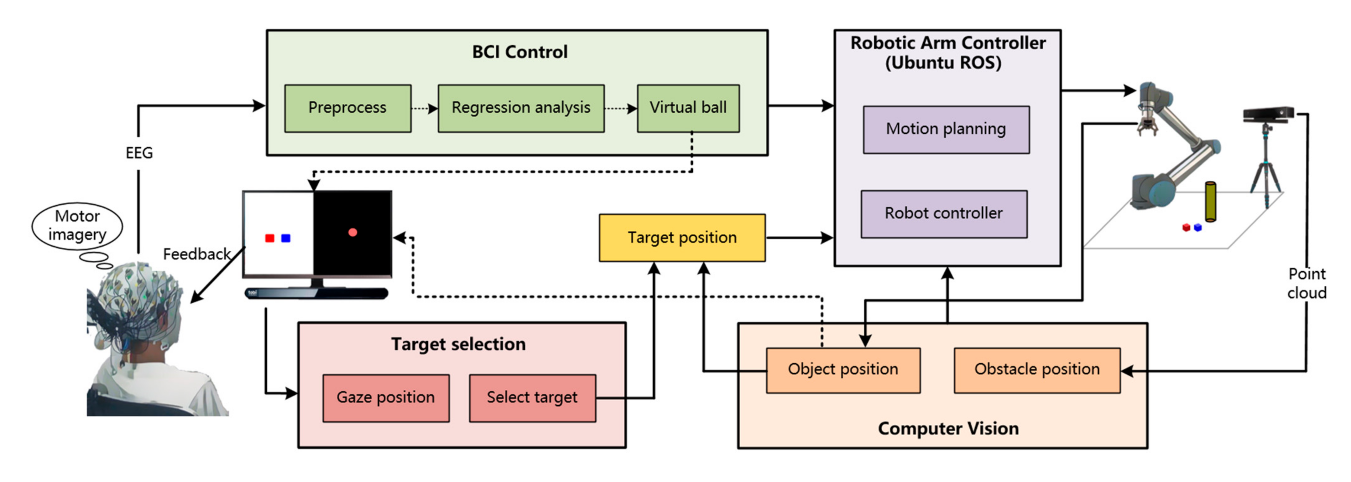
2.1. System Architecture
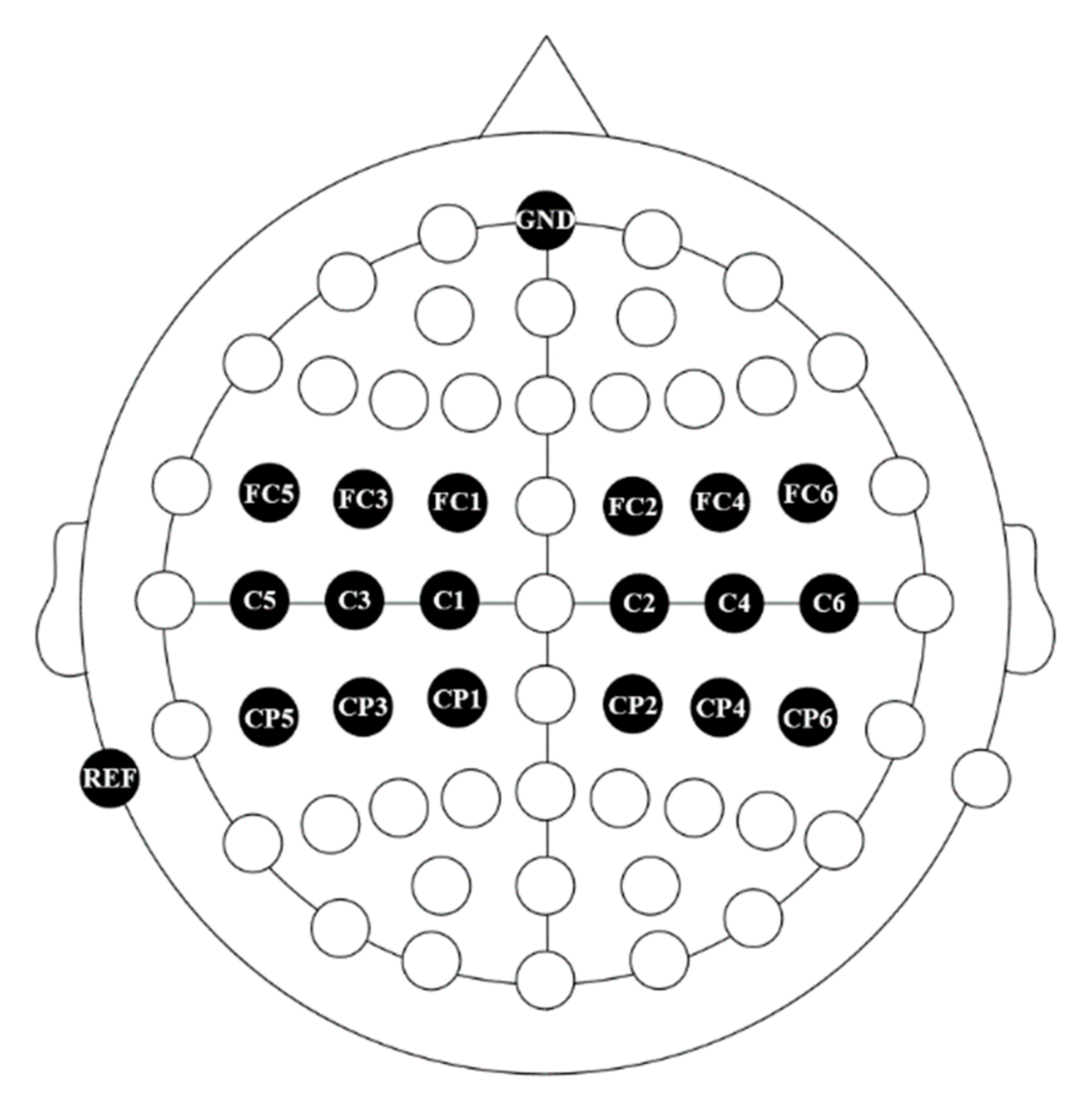
The architecture of the experimental setup is given in Figure 1, which demonstrates how the subject can control the robotic arm based on our proposed system. The whole system mainly consists of the following components: an EEG record device, an eye-tracker, a UR5 robotic arm, a USB camera, Kinect, and two computers. To settle the difficulty of multitarget grasping with obstacles that might be faced in daily life applications, we divided the reach and grasp process into three stages.
In the first stage, the subjects imagined different types of movement of their hands (right-hand movement, left-hand movement, both-hand movement, and relaxing), and the EEG signals of the subject were recorded by the BCI system. The signals were decoded to control the virtual ball, which was in front of the subject and moved continuously on a 2D plane. The position of the virtual ball would be transmitted in real time to the robotic arm controller installed on the robot operating system (ROS), which controlled the robotic arm to move. When the virtual ball stopped moving, so did the robotic arm. In the second stage, a scene camera mounted on the end effector of the UR5 robot would obtain videos of the workspace and identified the potential targets, which would be selected with a rectangle and displayed on the screen in front of the subject. An eye tracker fixed under the monitor detected the position of subjects’ gaze and controlled the movement of the mouse, assisting subjects in selecting the target. Once the target was chosen, the position would be sent to the robotic arm controller. In the third stage, the target would be grasped automatically after the robot controller obtained the detailed position. Moreover, a depth camera was used to locate the position of obstacles in the workspace, and the robotic arm would avoid the obstacle during motion planning.

2.1.1. BCI System

EEG signals were recorded by the Neuroscan SynAmps2 amplifier with a sampling frequency of 500 Hz. In this research, we selected 20 electrodes from an elastic ActiCap (Brain Products, Gilching, Germany) that attached standard Ag/AgCl 64 electrodes with the international 10–20 system [39], as shown in Figure 2. The left mastoid was adopted as the reference channel while the ground channel was located on the forehead. EEG data were acquired by keeping electrode impedances below 10 kΩ at the beginning of the experiment, and the electrode impedance would be checked again in the middle of each session to remain below 10 kΩ.
During EEG recording, a quiet environment was provided to keep the subjects’ attention focused. Participants were seated in a comfortable chair in front of an LCD screen at a distance of about 80 cm. They were asked to keep all muscles relaxed and avoid eye movements, blinks, swallowing, body adjustments, or other movements during the experiment. Following the signal acquisition, a notch filter at 50 Hz and common average reference (CAR) filter [40], as shown in Equation (1), were utilized to preprocess the raw EEG signals:
V i C A R ( t ) = V i ( t ) 1 n j = 1 n V j ( t ) ,
where Vi(t) is the potential between the reference and the ith electrode at time t, and n is the number of electrodes used in this study.
To evaluate the amplitudes in the mu frequency band for each user, an autoregressive (AR) model was built in the experiment as follows:
x t = i = 1 p a i x t i + ε ,
where xt is the estimated signal at time t, p is the order of the AR model, ε is a zero-mean white noise, and ai is the weight coefficient. The value of ai is estimated by the least squares criterion. The least squares criterion is used to adjust the weights to minimize the difference between the actual signal and the estimated signal predicted by Equation (2).
The sensorimotor rhythm amplitude of each subject is used to move the virtual ball and robotic arm in the current study. The movement of the virtual ball in the vertical direction is determined by the parameter KV, which is evaluated by [5]:
K V = w R V R V + w L V L V + d V ,
where dV is the offset. RV and LV are the amplitude on the right side and the left side, respectively. The initial values of wRV and wLV were both +1.0, and dV is 0.0. When the value of KV is negative or positive, the virtual ball is moved up or down, respectively.
The movement of the virtual ball in the horizontal direction is determined by the parameter KH, as follows [5]:
K H = w R H R H + w L H L H + d H ,
where dH is the offset. RH and LH are the amplitude on the right side and the left side, respectively. The initial values of wRH, wLH, and dH were +1.0, −1.0, and 0.0, respectively. When the value of KH is negative or positive, the virtual ball is moved left or right, respectively.
Previous research on ERD/ERS has shown that when the subjects perform unilateral hand motor imagination, the EEG amplitude of the ipsilateral sensorimotor area will increase, and the contralateral side will be inhibited. The virtual ball movement in the vertical direction was initially controlled by the sum of the amplitudes on both sides. Therefore, if the participants imagined both-hand movement, both RV and LV would decrease, the virtual ball was moved upwards. In contrast, when the subjects imagined both hands relaxing, the amplitude on the left side (LV) and right side (RV) would increase, and the virtual ball was controlled to move downward. The virtual ball movement in the horizontal direction was initially determined based on the difference between RH and LH. The control principle in the horizontal direction was the same as that in the vertical direction.
The weights and offsets in Equations (3) and (4) were not fixed values, and they would automatically adjust according to the least-mean-square (LMS) algorithm according to the previous trials. The adjusted parameters would minimize the difference between the real target location and the predicted target location, thereby making the subsequent EEG-based virtual ball control more accurate [5,41].

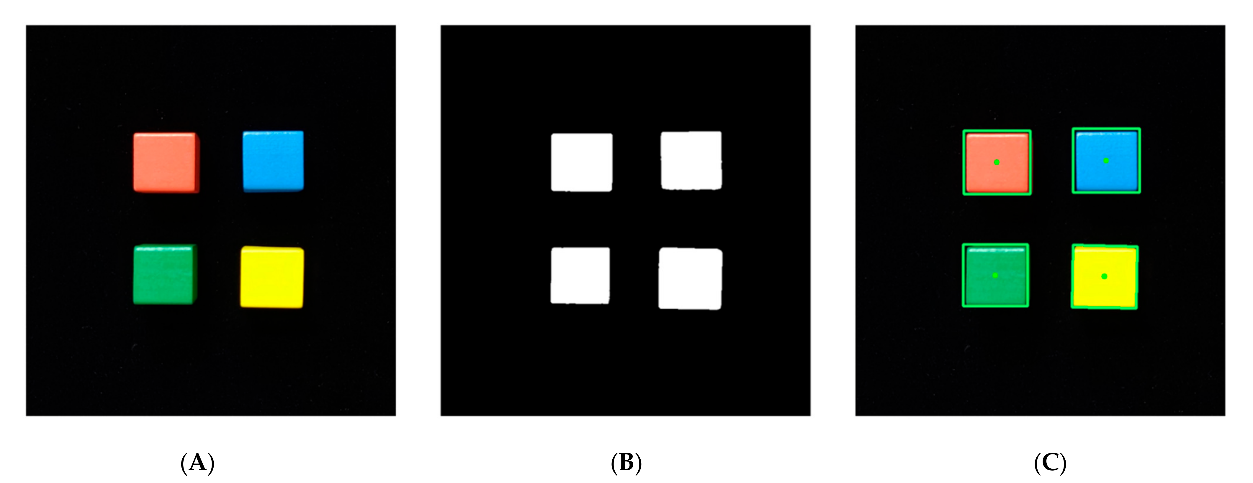
2.1.2. Object Identification and Target Selection

In this study, computer vision was utilized for object identification, and gaze tracking was chosen for target selection in the online task. For the object identification, a USB camera (1280 × 720 pixels) mounted on the gripper was employed to obtain the information of the workspace. The captured video was transmitted to the computer by USB3.0 port and presented on the monitor in front of the subjects. For the target selection, a low-cost desktop eye-tracker, Tobii eye-tracker 4C (Tobii Tech, Stockholm, Sweden), was mounted on the screen to detect the subject’s gaze position and map it to the computer to control the mouse cursor on the monitor in front of the subject. The gaze data were sent to the computer through the USB3.0 port in real time. Moreover, it was necessary to calibrate the eye tracker for each subject before the experiment.
Four kinds of cube blocks (30 × 30 × 30 mm) with different colors were used as target blocks in this study. The target blocks in the workspace were detected by the background subtraction algorithm based on their color. The object identification sample was demonstrated in Figure 3. The raw image was in red, green, blue (RGB) color space. Firstly, in order to relieve the influence of illumination change on object identification, the raw image was converted to the hue, saturation, value (HSV) color space. Secondly, the target blocks in the image would be identified based on the difference between colors and the threshold (Figure 3B). At last, all the blocks would be successfully identified through background subtraction, and the blocks would be outlined on the screen as potential targets by a green rectangle (Figure 3C). Once a left-click was taken in a potential target’s green rectangle, the target would be selected, and visual feedback would be offered by changing the color of the rectangle surrounding the selected target to red. The mouse cursor was controlled to move on the monitor based on the subjects’ gazed position. When the subjects moved the gaze-controlled mouse cursor into the green rectangle surrounding the desired target and held the cursor in the rectangle for more than 2 s, the left-click would be triggered and the detailed position of the selected target would be sent to the ROS system.

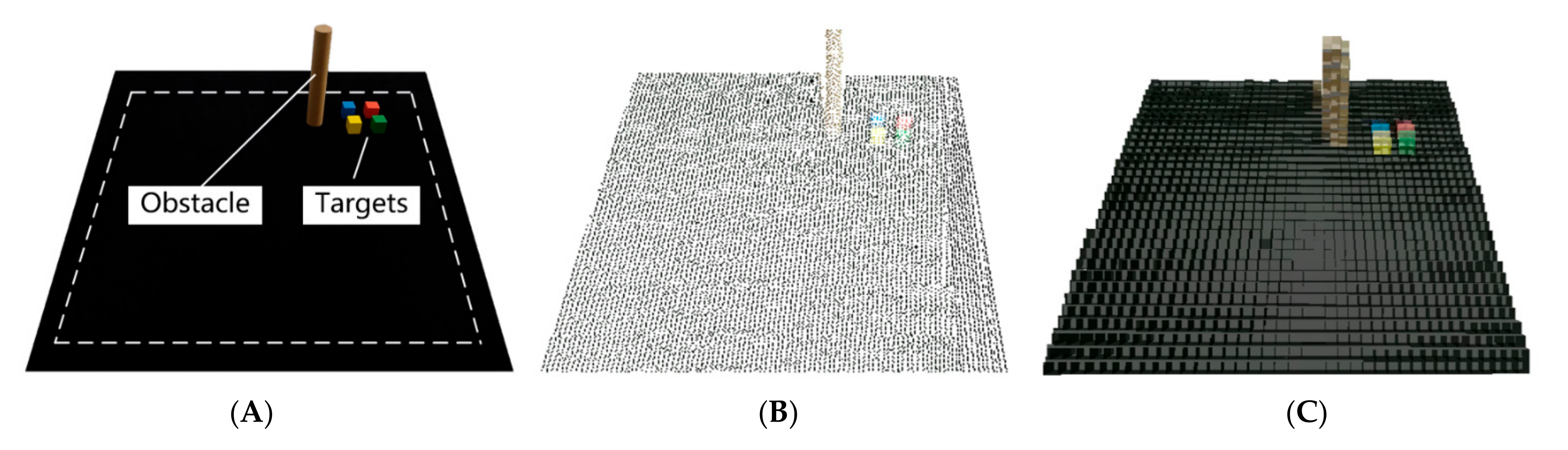
2.1.3. Robotic Arm Control and Obstacle Avoidance

A robotic arm with six DOFs, UR5 (Universal Robots, Odense, Denmark), was used in this research. The maximum working radius of the robotic arm was 0.85 m, and the moving range was limited within the workspace to avoid collisions with objects and subjects outside the workspace. The gripper equipped at the end of the UR5 was nGripper90 (NONEAD Corporation, Suzhou, China) with two fingers. The robotic arm was driven by ROS running on the Ubuntu operating system. The inverse kinematics solver on ROS could convert the position and orientation of the end effector to the corresponding joint positions. Consequently, we could directly provide the robotic arm control system with the endpoint information, and the solver would calculate the inverse kinematic solution and plan the route to the target location. The solver used in this experiment was TRAC-IK [42]. Compared with the traditional solver, it is faster and more reliable.
To simulate a more realistic scene of disabled people’s daily life in this study, we added obstacles to the experimental workspace, which made the task more difficult to finish. If the robotic arm was directly controlled by the EEG to avoid the obstacle, the success rate of online tasks would be possibly low; also, the subject’s mental burden would be huge. In order to overcome the above difficulties, a depth camera, Kinect v2 (Microsoft, Redmond, WA, USA), was employed to collect the cloud point information of the workspace, so that the position of the obstacle would be detected and sent to the robotic arm controller.
The Kinect, mounted on the tripod, was placed on the left side of the workspace, 0.6 m high from the table. Point clouds collected by Kinect outside the workspace were deleted using a passthrough filter to reduce the interference. A voxel grid filter was then applied for downsampling in order to cut down the amount of calculation while not destroying the geometric structure of the point clouds. To remove some outliers, the RadiusOutlierRemoval filter was then utilized in this study. After the preprocessing, the filtered point clouds (Figure 4B) were converted into Octomap (Figure 4C) [43] in ROS and added to its workspace. Therefore, the obstacle could be avoided by the robotic arm during motion planning on ROS. For Octomap, the probability that for each leaf node m could be calculated based on measurements z1:t:
P ( m | z 1 : t ) = [ 1 + 1 P ( m | z t ) P ( m | z t ) 1 P ( m | z 1 : t 1 ) P ( m | z 1 : t 1 ) P ( m ) 1 P ( m ) ] 1 ,
where zt is current measurement at time t, P(m) is prior probability, and P(m|z1:t−1) denotes the previous estimation. P(m|zt) represents the probability that voxel m is occupied at time t.

2.2. Experimental Paradigm

2.2.1. Subjects

Seven right-handed subjects (average age: 23.1 ± 0.6 years, four males) were recruited from the campus to participate in this study. All of them were naïve for BCI experiment and without any history of neurological disease [5,29,33]. Each subject was informed of the method and research activities of this study, and the informed consent was signed before they participated in the experiment. All procedures and protocols were in accordance with the Helsinki Declaration and were approved by the Ethics Committee of Southeast University.

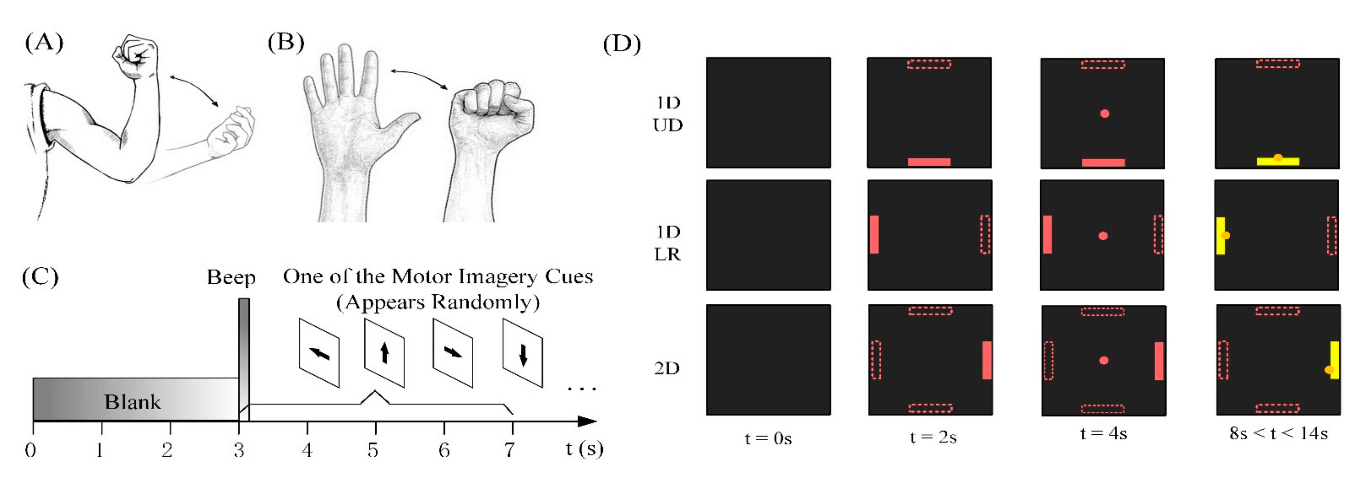
2.2.2. MI without Feedback

The ERD/ERS phenomenon were identical for everyone. Therefore, it is necessary to obtain the EEG data during MI without feedback experiments before the training experiments for all the subjects. The EEG data in this stage were used to obtain the optimal frequencies, spatial channels, and the action of MI, maximizing the distinction between different MI tasks. These features would be used in the training experiments.
There were two sessions in this stage, and each session was divided into nine runs. In the MI without feedback experiments, the subjects were asked to imagine three different actions. From run 1 to run 3, the MI action was the flexion and extension of the forearm (Figure 5A, action 1). The opening and closing of the hand were imagined from run 4 to run 6 (Figure 5B, action 2). In the last three runs, the subjects were asked to imagine an action they are conversant with. Each run consisted of thirty consecutive trials separated from each other by 3 s. The timing scheme of an individual trial is given in Figure 5C. The screen was black at the beginning of a trial (t = 0 s), and the subject was instructed to stay relaxed and still. After three seconds (t = 3 s), a black arrow, which pointed to one of the four directions (left, right, up, or down, corresponding to movement imagination of left hand, right hand, both hands, or relaxing, respectively) randomly, was shown in the middle of the black screen, together with a 0.2 s auditory beep to prompt the subject to start MI. The cue was held for 4 s and the subjects were instructed to start MI according to the cue. After four seconds (t = 6 s), the screen would return to black and the subjects had three seconds to relax before the next trial.

2.2.3. Virtual Ball Movement Control Training

To improve the ability to control the robotic arm continuously based on MI, the subjects were asked to perform the virtual ball control training by MI. We designed the training experiments with progressively increasing difficulty, and each subject’s MI action, frequency, and main electrodes were all set according to the results of the MI without feedback experiments.
As shown in Figure 5D, the training experiments were divided into three stages. In the first stage, the subjects were instructed to control the virtual ball move upward or downward in one dimension (1D, UD) by MI. In the second stage, the virtual ball was moved left or right (1D, LR). In the third stage, the virtual ball was moved in two dimensions (2D). The subjects were instructed to imagine right-hand movement, left-hand movement, both-hand movement, or relaxing to control the virtual ball movement to the right, left, up, or down, respectively. Each session consisted of 6 runs, and there were 44 trials of virtual ball movement in each run. In the 1D virtual ball training stage, only when the average correct rate in three consecutive runs for one session reached 90% could subjects start the next training stage. The condition for completing the 2D virtual ball control training of each subject was that the average correct rate in three consecutive runs exceeds 80%. At the beginning of each trial (t = 0), there was a 2 s preparation period with a black screen for the subject. When t = 2 s, the pink target block randomly appeared at different fixed locations on the screen. After 2 s (t = 4 s), the pink virtual ball appeared on the center of the screen and began to move according to the subject’s MI-based EEG. Each subject was given up to 10 s in each trial to move the virtual ball to hit the target block. Once the virtual ball hit the target, the color of the virtual ball and target would change from pink to yellow. There would be a 3 s break before the next trial.
Due to the individual differences, each person’s training time was different, depending on their ability and performance, but there were no more than 7 sessions for each stage. Each subject was not trained on the same day, and the average interval between sessions was 5.16 ± 2.47 days. All seven subjects participated in the first and second stages of the training experiments, but subject 7 dropped out of the third stage of training and the rest of the experiments due to scheduling conflicts. Extra sessions were designed to estimate the chance performance for each training stage; to be more specific, there were 528 trials for each training stage. The experimental paradigm was the same with 1D and 2D training experiments. However, the virtual ball was controlled by random EEG signals. All the virtual ball control experiments in this study were presented by an official stable version of BCI2000 software [44].

2.2.4. Online Robotic Arm Control Experiments

The experimental environment of the online experiment is displayed in Figure 6A. The monitor was divided into the virtual ball movement area and the USB camera display area. The online experiments consisted of three tasks with increasing difficulty, and the experiment time of each task was less than two and a half hours, including the rest time. A square area (60 cm × 60 cm) was defined on the table as the workspace to place the targets and obstacles in this experiment, as illustrated in Figure 6B. For each trial, the initial position of the robotic arm end-effector was in the center of the workspace. When the experiment started, the subject had a waiting time of 3 s to calm down and prepare for MI. The virtual ball movement area on the monitor was blank. After 3 s, the virtual ball appeared at the center of the virtual ball movement area and began to move based on participants’ MI-based EEG.
Meanwhile, the position of the virtual ball was sent to ROS in real time to drive the robotic arm to move. When the virtual ball hit the area boundary or the movement reached 10 s, the virtual ball would stop moving. Consequently, the robotic arm would temporarily stop moving. Next, the subject needed to use the eye tracker to drive the mouse movement on the screen, and select the target on the screen. Once the target was chosen, its position would be transmitted to the robot arm control system immediately to drive the robotic arm to grasp the target automatically. During the entire process of the experiment, the robotic arm control system would detect the position of the obstacle through the depth camera and direct the robotic arm to bypass the obstacle.
In task A, the experiment was one target without an obstacle. Subjects were asked to complete only one target-grabbing task without any obstacles in the workspace. Eighty random locations were selected in the workspace to place the target block, and only one block was placed on the workspace in each trial. Therefore, there were 80 single trials for each subject to complete in this task. When the movement of the robotic arm was temporarily stopped due to the end of EEG control, it would be regarded as a failure trial if there was no target in the view of the camera. Apart from this, if the grasp failed due to the error of visual guidance or the robotic controller, the trial also would be defined as a failure.
In task B, there was one target with an obstacle. A cylindrical obstacle with a radius of 2.5 cm and a height of 25 cm was placed in the workspace. Only one target was placed in the workspace in each trial. Moreover, the cylindrical obstacle was placed at a position between the initial position of the robotic arm end-effector and the target block to ensure that the robotic arm needed to avoid the obstacle during movement. This task included the same target location and experiment sequence as task A. The definition of failure trial was the same as in the first task.
In task C, the experiment of four targets with an obstacle was performed. Compared with task B, three additional blocks were placed around the target, and the distance between two target blocks was less than 3 cm. In order to distinguish which one was the target, only one green block was placed as the target, and the other three blocks were other colors. In each trial, subjects were asked to grasp the green block. The obstacle was placed the same as that in task B.

3. Results

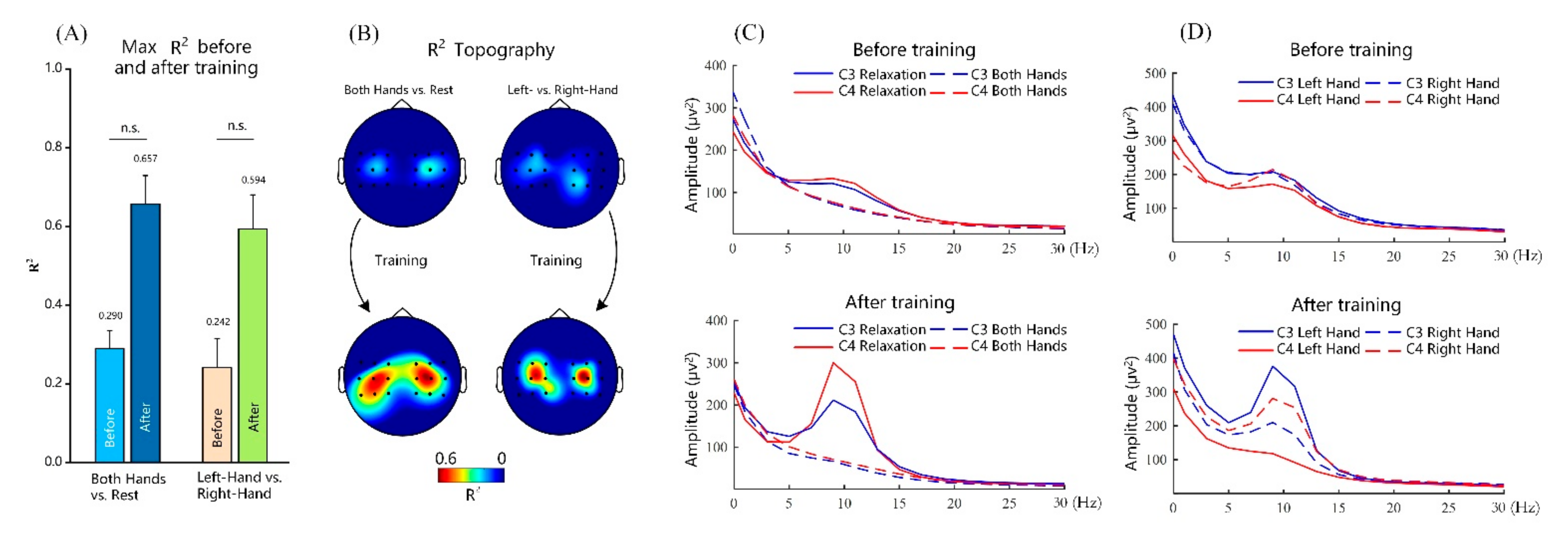
3.1. Performance of MI without Feedback

After the motor imagery without feedback experiments, the best placement of the electrodes, MI action, and frequency for each subject were selected and are reported in Table 1, according to the highest R2 value under different MI actions. It can be found that the best features of different subjects vary from person to person. The best feature was obtained from a frequency band which can be uniquely identified by a center frequency and a bandwidth of 3 Hz. The best electrode on the left is C3 or CP3, and the best electrode on the right is C4 or CP4. As is shown in Table 1, all of the frequency bands were chosen from the mu rhythm.

3.2. Performance of Virtual Ball Control Training

All seven subjects participated in the 1D virtual ball control training. In the 2D training stage, subject G withdrew from the experiment due to scheduling conflicts. The average success rates of each subject for virtual ball movement control before and after training were calculated. Suppose that Ts is the number of the success target hit trials and TAll is the total number of the trials. The average success rate was defined as follows:
R = T S T A l l ,
which is different from another study [13]. They defined an indicator excluding those trials when neither the correct target nor an incorrect target was hit. Moreover, we defined the failed trials corresponding to those tasks when the virtual ball hit the wrong target or failed to hit any target within the limited time. Meanwhile, the completion time of all the trials was recorded, which was defined as the duration from when the virtual ball started to move to when it hit the target.
The average success rates of each subject in 1D UD, 1D LR, and 2D virtual ball movement control are displayed in Figure 7A–C. In the first session of 1D UD virtual ball control training, the average success rate for all the subjects was 41.7% ± 14.8% and rose to 89.1% ± 5.4% at the last training session. The average success rate increased by nearly 115% for 1D UD training. The average success rate increased from 45.9% ± 17.3% in the first session to 88.2% ± 5.3% in the last session and had a more than 90% increase in the 1D LR virtual ball control training. The 1D control training was shown to be helpful to subjects’ performance in 2D control training. The average success rate at the first session for 2D virtual ball movement control (49.9% ± 9.2%) was higher than that at 1D virtual ball movement control. In the last session of 2D virtual ball control training, the average success rate improved by over 60% compared to the first session.
Due to the differences between individuals, the number of training sessions needed for each participant to achieve the goal of each training stage was different. Among all the subjects, subject B participated in 17 sessions for virtual ball control training and had the maximum participation rate. On the contrary, subject E had the least total number of training sessions, with only 11 sessions. The chance level performance is 22.1% for 1D virtual ball control and 15.2% for 2D virtual ball control, which is indicated by red dotted lines in the figure. After training, the average success rate of the virtual ball control for all the subjects is much higher than the chance level. The three graphs in Figure 7D from top to bottom show the average completion time in success trails for virtual ball control training in 1D UD, 1D LR, and 2D, respectively. The average completion time for 1D UP virtual control training for all the subjects in the first session was 6.7 ± 0.4 s, which was reduced to 5.5 ± 0.2 s in the last session. Similarly, as the training continued, there was a gradual reduction in the average completion time for the 1D LR and 2D virtual ball control training, reaching 5.3 ± 0.2 s and 5.4 ± 0.1 s, respectively.
Figure 8A provides the changes in the maximum sensorimotor R2 values before and after the virtual ball control training. The maximum sensorimotor R2 values were evaluated as the regression output between the task conditions and the EEG power. Before the training, the average maximum R2 value of the subjects between the MI of both hands and relaxation was 0.290. The R2 value between the MI of the left hand and right hand was 0.242. After a series of training sessions, the average maximum R2 values increased to 0.657 and 0.594, separately. The statistical results revealed that the virtual ball training could significantly improve the correlation between EEG and different MI labels. The R2 topographies for subjects at 12 Hz before and after the virtual ball control training are shown in Figure 8B. The areas with larger R2 values were concentrated near the electrodes of C3 and C4, which were the same as the sensorimotor area stimulated by MI. After the training, the R2 values increased significantly, but the area where the maximum R2 values were located did not change.
Figure 8C,D shows the group-level average voltage spectra across all the subjects and sessions at the C3 and C4 electrodes before and after virtual ball control training. It should be noted that the amplitude difference between different mental states (MI of both-hand movement versus relaxing and left-hand movement versus right-hand movement) is focused at mu rhythm. From Figure 8C, we can observe that the amplitudes at C3 and C4 electrodes are smaller during the subjects imagining both their hands moving than during the subjects imagining relaxing, which represented the ERD phenomenon. After the virtual ball control training, the difference in EEG amplitude between the imagination of both hands and relaxation increased significantly at the mu rhythm. As can be seen from Figure 8D, before training, it is difficult to distinguish the EEG amplitude at C3 and C4 electrodes between the imagination of the left hand and right hand. After training, on both sides of the sensorimotor cortex, the difference in EEG amplitude becomes higher than before training.
In this study, we further analyzed the changes of EEG topography on the subject’s sensorimotor cortex in the different training stages. Figure 9 demonstrates ERD/ERS topographical map in the mu frequencies of subject D during the three stages of virtual ball control training. From the last session, the contralateral ERD and ipsilateral ERS were clearly observed from the topographical map when the subject imagined unilateral hand movement, and the power of the contralateral motor cortex was suppressed compared with the relaxation status. When the subject imagined both-hand movement, the bilateral ERD also could be clearly observed in the last session. However, this ERD/ERS phenomenon was not obvious in the first session, and the situation improved in the middle session. As the training continued, the energy of the sensorimotor cortex on both sides of the brain in the mu rhythm increased when the subject was in the relaxed status, and the contralateral ERD and ipsilateral ERS became more obvious in the movement imagination. Combined with the changes of R2 values and voltage spectra, these changes provided convincing evidence that the enhanced behavioral improvement shown in the virtual ball control training was accompanied by coincident neural changes in sensorimotor modulation.

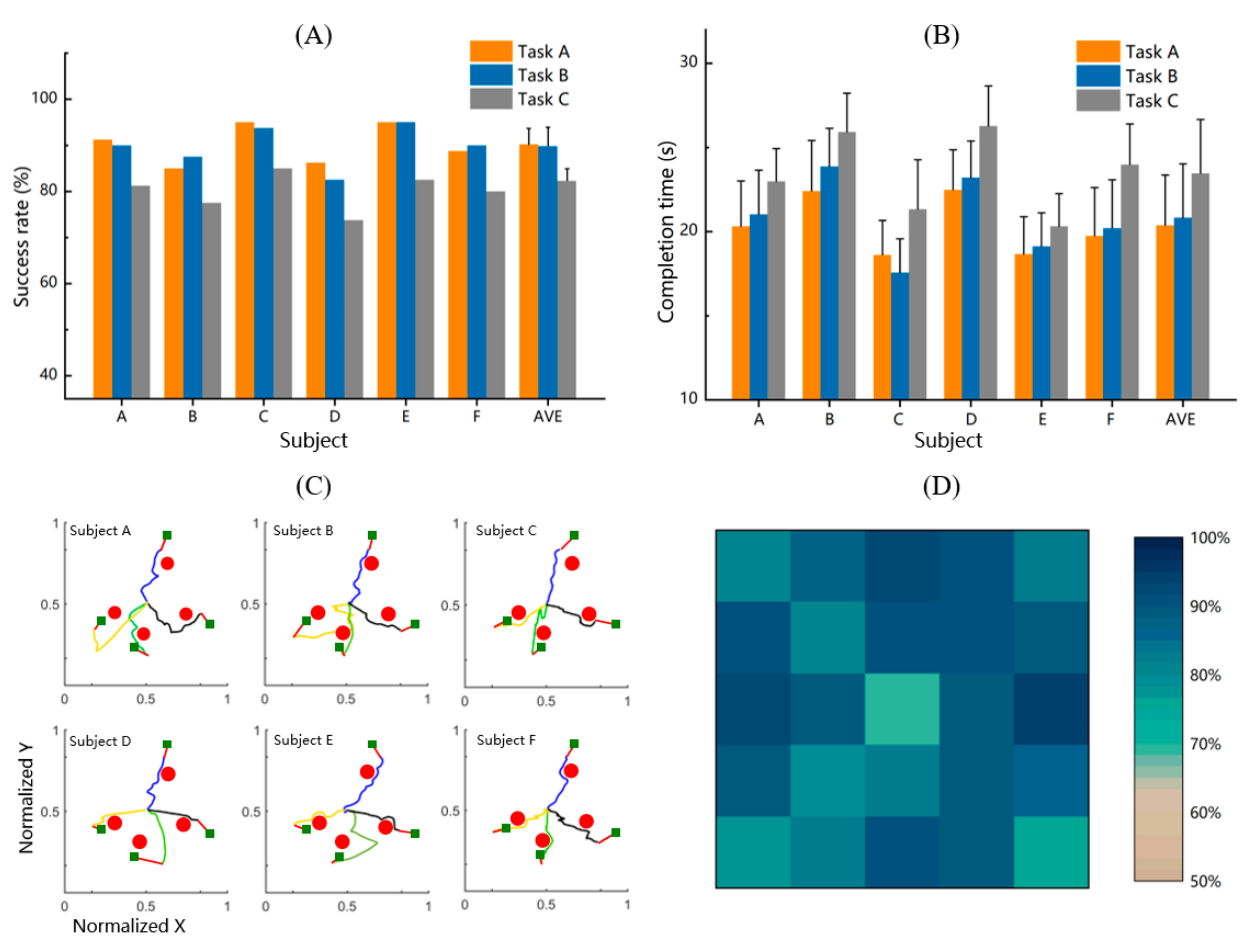
3.3. Performance of Online Experiments

Figure 10 displays the performance of online experiments, where the subjects were instructed to grasp the target via the robotic arm. It should be noted that there were three steps for the subjects to complete in the online task using our hybrid control system. In the first step, the movement of the robotic arm was accompanied by the EEG-controlled virtual ball movement (the robotic arm was continuously controlled to move to the surrounding area above the target on a 2D plane). In a subsequent step, the target was detected by computer vision and selected by the subject’s gaze point. In the last step, the robotic arm reached and grasped the target automatically. The average success rates of the three tasks in the online experiment were 90.2%, 89.2%, and 82.3%, respectively, as shown in Figure 10A. All the unsuccessful trials in the online experiments were due to the error of EEG control or the wrong target being selected through the eye-tracker. There was only one target in task A and task B, and the only difference was that there was an obstacle in the workspace in task B. The average success rate and the average completion time of successful trials for all the subjects in task A and task B were close, and the main reason was that both tasks had only one target in each trial and the robotic arm could always avoid obstacles successfully. The success rate was reduced to 82.3% and the average completion time of successful trials increased to 23.5 ± 3.2 s in task C mainly because the subjects had to select the correct target from four crowded blocks on the screen. Subject C and subject E had a higher success rate than other subjects in the online experiment and spent less time than other subjects to complete the task.
The trajectory samples of the robotic arm for the online experiments of one target with an obstacle are displayed in Figure 10C for all six subjects. The red circle in the figure represents the position of the obstacle, and different colors are used to distinguish the trajectories of different targets. The red line indicates that the robotic arm grasped the target automatically. Some EEG-controlled trajectories closed to the target directly while others had redundancy. Once the target was selected via the user’s gaze point, there was no more redundancy in the remaining trajectory. The workspace was divided into 25 regions of equal size, and the success rate distribution for each region of the workspace across all subjects and all online experiment tasks is shown in Figure 10D. The middle of the workspace had a lower success rate of 69.4%. The four regions with the highest success rate were in the middle of the four edges of the workspace, mainly due to the fact that these regions were similar to the positions where the target appeared in the 2D virtual ball control training.
The EEG signals of all subjects and all tasks were recorded to demonstrate more details in the online experiments. We analyzed the EEG signals of the C3 electrode over the left hemisphere and the C4 electrode over the right sensorimotor cortex from these trials, as shown in the trajectory sample in Figure 10C. Figure 11 shows the time–frequency spectral changes for these trials from −2 to 6 s, and the movement of the robotic arm is guided by EEG during these periods. The vertical dotted black line at 0 s indicates the time when the virtual ball appears on the screen, and the virtual ball and robotic arm begin to move at 1 s. The baseline spectra were estimated from the EEG signal selected from −2 to 0 s during which the subject remained in a holding state. Note that the ERD (blue color) and ERS (red color) patterns can be observed from around 0.3 to 0.5 s after the virtual ball appears. Strong ERD/ERS can be seen in mu bands. Moreover, weak ERD in the beta band also existed.

4. Discussion

In the previous studies on the control of assistive manipulators based on BCI to assist patients suffering from motor impairment, the invasive BCI approaches have shown that control of the multi-DOF robotic devices to complete daily activities in a laboratory setting is possible [3,11,12]. Nevertheless, such BCI systems driven by invasive technology are limited by the medical risks associated with surgery and implantation of the microelectrode array in the cortex. Currently, the EEG signals recorded via noninvasive BCI technology have a low signal-to-noise rate. Therefore, the control of robotic arms with many degrees of freedom is still difficult, especially in a complex environment with obstacles, which restricts the practical application of noninvasive BCI in the control of robotic arms. Some studies have come up with another method based on hybrid BCI, which combines MI with evoked BCIs to control the robotic arm. However, the evoked BCIs will cause distraction and brain burden. Additionally, EEG was combined with electromyography (EMG) to control external devices in previous research [18,23].
In this study, a group of healthy subjects started from the simplest MI without feedback experiment and gradually mastered the control of a virtual ball’s movement in the 2D plane through MI after a series of virtual ball control training experiments with progressively increasing task difficulty. Due to the relatively lower control accuracy of the robotic arm using MI independently, the users only need to move the robotic arm to the approximate area above the target through BCI and then select the target through the gaze point to obtain the accurate position of the target. Finally, the robotic arm performs automatic grasping. The online control implemented in this study is quite similar to that required in daily activities, where there are obstacles in the workspace with the target surrounded by other objects. The experimental results have demonstrated that all the subjects can control a robotic arm to finish the online tasks using noninvasive BCI combined with computer vision technology in complex environments.
The results of the MI without feedback for all the subjects show that EEG is different when subjects imagined different actions, which is consistent with the previous research [45]. The MI without feedback experiments are conducted to select the best placement of the electrode, MI action, and frequency for each subject. In this way, the control performance of the robotic arm for the participants is greatly improved.
ERS and ERD have been considered to be the product of specific cognitive processes, which are associated with the motor nervous system [46]. The modulation of the mu rhythm is quantified by the R2 values and the topographic map (Figure 8A and Figure 9). As the training continued, we found that users’ ability to control the virtual ball gradually improved. Moreover, the ERD/ERS was more obvious over time, indicating that the MI training with feedback could regulate the movement rhythm of subjects. This further validated that MI training could promote cognitive processes and might be essential for BCI control [47].
Throughout the virtual ball control training experiments, we observed that there were significant differences in the ability of different subjects to control the virtual ball. The success rate of subject G after five training sessions in 1D UD was 62.5 ± 13.2%, while the success rate of subject C training for the first time reached 62.5 ± 9.2%. We also found that the performance of the online experiment was directly affected by the virtual ball control training performance. The success rate of subject E in online experiment task A was up to 95.0%, and the average success rate for 2D virtual ball was 87.1%. The subject also reported that it was easier for her to control the virtual ball and the robotic arm. We noticed that the experiment performance was also related to the state of the subjects during the experiment. The success rate of the subjects in the bad state (an inattentive or distracted state) in the virtual ball control training and online experiment would decrease compared with the previous session.
Several former typical hybrid BCI studies focused on decoding EEG signals to discrete commands [14,32]. It is a challenge to generate a continuous control signal [48]. Our system was based on an online regression model of MI-EEG, providing natural, continuous, and efficient operations. The use of computer vision and eye-tracker can also reduce the brain burden caused by long-term mental activities. To sum up, the proposed continuous hybrid BCI system showed potential in complex reach and grasp tasks with obstacles.

5. Limitations and Future Work

The proposed system was designed to be user-friendly for potential users, including healthy people and the disabled. The aim of our work is to investigate the potential application of the proposed continuous hybrid BCI system. Due to the MI-based BCI systems’ certain requirement for users to master motor imagination, the MI without feedback stage (Section 2.2.2) and the virtual ball movement control training stage (Section 2.2.3) were designed to obtain the optimal frequency-channel parameters of the proposed system and make naïve subjects master the MI paradigm. This method was verified and performed well for both naïve healthy subjects and real patients to master 1D and 2D MI control in previous studies [5,49,50,51].
The proposed system still has several limitations to be settled for practical applications. On the one hand, real patients were not recruited for the experiment. For the present, the subjects in our experiments were all healthy people with functional limbs. Several former works have also designed different kinds of BCI control strategies and verified the performance of their methods on healthy subjects [13,15,33,37]. Even though the MI-based training method was verified and performed well for both naïve healthy subjects and real patients, it would be better to further verify whether the proposed hybrid BCI system is effective for real patients. On the other hand, the targets grasped in online experiments are simple at present, but the shapes of the targets that the users intend to grab are various in reality. Moreover, the robotic arm is fixed on the desktop to finish the tasks in a local field, but it cannot grab a target outside the workspace.
We are also trying to make some additional effort to enhance this system and expand the continuous hybrid control strategy to more complex scenarios in the future. Practical functional modules (e.g., a mobile platform or a wheelchair) could be integrated into the BCI system to extend the system to broader scenarios in daily lives. In addition to expanding the function of such BCI systems, it is necessary to recruit real patients to participate in the following research. After all, healthy and disabled subjects are both the end-users of the proposed system.

6. Conclusions

In this study, we have proposed a noninvasive EEG-based hybrid BCI control system for a robotic arm. Such a system enables subjects to complete reach and grasp tasks in a 3D environment with obstacles. After a period of MI training with feedback, all the subjects mastered the ability to control the virtual ball on a two-dimensional plane via BCI. With the assistance of gaze tracking and obstacle detection, the subject can control the robotic arm to pick up a target and avoid obstacles accurately. The subject only needs to control the robotic arm to continuously move to the approximate area above the target on a 2D plane through MI, which will reduce the user’s brain burden and improve the accuracy of the task. The experimental results demonstrate that all subjects can complete the online tasks with a high success rate through the proposed robotic arm control system. Moreover, we also find that the motor imagery can promote cognitive processes, which may be of great significance for patients’ neural rehabilitation training in the future. The proposed system combining BCI with computer vision, gaze detection, and semiautonomous guidance drastically improves the accuracy of reach and grasp tasks and reduces the brain burden caused by long-term mental activities.

Author Contributions

Conceptualization, B.X. and W.L.; methodology, W.L. and D.L.; validation, W.L. and B.X.; formal analysis, D.L. and K.Z.; investigation, D.L. and M.M.; resources, W.L.; data curation, W.L. and B.X.; writing—original draft preparation, W.L.; writing—review and editing, W.L. and B.X.; visualization, G.X. and A.S.; supervision, M.M. and G.X.; funding acquisition, B.X. All authors have read and agreed to the published version of the manuscript.

Funding

This work was partially supported by grants from the Basic Research Project of Leading Technology of Jiangsu Province (No. BK20192004) and the National Natural Science Foundation of China (No. 62173088, No. 62173089, and No. 62101189).

Institutional Review Board Statement

Not applicable.

Informed Consent Statement

Not applicable.

Data Availability Statement

The raw data supporting the conclusions of this article are available on request to the corresponding author.

Acknowledgments

The authors would like to thank all the volunteers who participated in the experiments.

Conflicts of Interest

The authors declare that the research was conducted in the absence of any commercial or financial relationship that could be construed as a potential conflict of interest.

References

  1. McFarland, D.J.; Wolpaw, J.R. Brain-Computer Interfaces for Communication and Control. Commun. ACM 2011, 54, 60–66. [Google Scholar] [CrossRef] [PubMed] [Green Version]
  2. Zhu, Y.; Li, J. A Hybrid BCI Based on SSVEP and EOG for Robotic Arm Control. Front. Neurorob. 2020, 14, 583641. [Google Scholar] [CrossRef] [PubMed]
  3. Hochberg, L.R. Reach and grasp by people with tetraplegia using a neurally controlled robotic arm. Nature 2012, 485, 372–375. [Google Scholar] [CrossRef] [PubMed] [Green Version]
  4. Allison, B.Z.; Brunner, C.; Kaiser, V.; Müller-Putz, G.R.; Neuper, C.; Pfurtscheller, G. Toward a hybrid brain-computer interface based on imagined movement and visual attention. J. Neural Eng. 2010, 7, 26007. [Google Scholar] [CrossRef] [PubMed]
  5. Wolpaw, J.R.; McFarland, D.J. Control of a two-dimensional movement signal by a noninvasive brain-computer interface in humans. Proc. Natl. Acad. Sci. USA 2004, 101, 17849–17854. [Google Scholar] [CrossRef] [PubMed] [Green Version]
  6. McFarland, D.J.; Sarnacki, W.A.; Wolpaw, J.R. Electroencephalographic (EEG) control of three-dimensional movement. J. Neural Eng. 2010, 7, 36007. [Google Scholar] [CrossRef] [Green Version]
  7. Meng, J.; Streitz, T.; Gulachek, N.; Suma, D.; He, B. Three-Dimensional Brain-Computer Interface Control Through Simultaneous Overt Spatial Attentional and Motor Imagery Tasks. IEEE Trans. Biomed. Eng. 2018, 65, 2417–2427. [Google Scholar] [CrossRef]
  8. Duan, X.; Xie, X.; Xie, X.; Meng, Y.; Xu, Z. Quadcopter Flight Control Using a Non-invasive Multi-Modal Brain Computer Interface. Front. Neurorobot. 2019, 13, 23. [Google Scholar] [CrossRef]
  9. Huang, Q.; Zhang, Z.; Yu, T.; He, S.; Li, Y. An EEG-/EOG-Based Hybrid Brain-Computer Interface: Application on Controlling an Integrated Wheelchair Robotic Arm System. Front. Neurosci. 2019, 13, 1243. [Google Scholar] [CrossRef] [Green Version]
  10. Utama, J.; Saputra, M.D. Design of electric wheelchair controller based on brainwaves spectrum EEG sensor. IOP Conf. Ser. Mater. Sci. Eng. 2018, 407, 12080. [Google Scholar] [CrossRef] [Green Version]
  11. Chowdhury, A.; Meena, Y.; Raza, H.; Bhushan, B.; Uttam, A.; Pandey, N.; Hashmi, A. Active Physical Practice Followed by Mental Practice Using BCI-Driven Hand Exoskeleton: A Pilot Trial for Clinical Effectiveness and Usability. IEEE J. Biomed. Health Inf. 2018, 22, 1786–1795. [Google Scholar] [CrossRef]
  12. López-Larraz, E.; Trincado-Alonso, F.; Rajasekaran, V.; Perez-Nombela, S.; del-Ama, A.; Aranda, J.; Minguez, J. Control of an Ambulatory Exoskeleton with a Brain–Machine Interface for Spinal Cord Injury Gait Rehabilitation. Front. Neurorobot. 2016, 10, 359. [Google Scholar] [CrossRef] [PubMed]
  13. Meng, J.; Zhang, A.; Bekyo, A.; Olsoe, J.; Baxter, B.; He, B. Noninvasive Electroencephalogram Based Control of a Robotic Arm for Reach and Grasp Tasks. Sci. Rep. 2016, 6, 38565. [Google Scholar] [CrossRef] [PubMed] [Green Version]
  14. McMullen, D.; Hotson, G.; Katyal, K.; Wester, B.; Fifer, M.; McGee, T.; Harris, A. Demonstration of a Semi-Autonomous Hybrid Brain-Machine Interface Using Human Intracranial EEG, Eye Tracking, and Computer Vision to Control a Robotic Upper Limb Prosthetic. IEEE Trans. Neural Syst. 2014, 22, 784–796. [Google Scholar] [CrossRef] [PubMed] [Green Version]
  15. Xu, Y.; Ding, C.; Shu, X.; Gui, K.; Bezsudnova, Y.; Sheng, X.; Zhang, D. Shared control of a robotic arm using non-invasive brain–computer interface and computer vision guidance. Rob. Auton. Syst. 2019, 115, 121–129. [Google Scholar] [CrossRef]
  16. Mondini, V.; Kobler, R.J.; Sburlea, A.I.; Müller-Putz, G.R. Continuous low-frequency EEG decoding of arm movement for closed-loop, natural control of a robotic arm. J. Neural Eng. 2020, 17, 46031. [Google Scholar] [CrossRef]
  17. Chen, X.; Zhao, Y.; Wang, Y.; Xu, S.; Gao, X. Control of a 7-DOF Robotic Arm System With an SSVEP-Based BCI. Int. J. Neural Syst. 2018, 28, 1850018. [Google Scholar] [CrossRef] [PubMed]
  18. Lebedev, M.A.; Nicolelis, M.A.L. Brain-machine interfaces: Past, present and future. Trends Neurosci. 2006, 29, 536–546. [Google Scholar] [CrossRef]
  19. Nicolelis, M.A.L. Brain-machine interfaces to restore motor function and probe neural circuits. Nat. Rev. Neurosci. 2003, 4, 417–422. [Google Scholar] [CrossRef]
  20. Clancy, K.B.; Mrsic-Flogel, T.D. The sensory representation of causally controlled objects. Neuron 2021, 109, 677–689. [Google Scholar] [CrossRef]
  21. Vidal, J.J. Real-time detection of brain events in EEG. Proc. IEEE 1977, 65, 633–641. [Google Scholar] [CrossRef]
  22. Ahn, S.; Kim, K.; Jun, S.C. Steady-State Somatosensory Evoked Potential for Brain-Computer Interface-Present and Future. Front. Hum. Neurosci. 2015, 9, 716. [Google Scholar] [CrossRef] [PubMed] [Green Version]
  23. Müller-Putz, G.; Leeb, R.; Tangermann, M.; Höhne, J.; Kübler, A.; Cincotti, F.; Mattia, D.; Rupp, R.; Müller, K.-R.; Millán, J.d.R. Towards Noninvasive Hybrid Brain–Computer Interfaces: Framework, Practice, Clinical Application, and Beyond. Proc. IEEE 2015, 9, 716. [Google Scholar] [CrossRef]
  24. Nierhaus, T.; Vidaurre, C.; Sannelli, C.; Mueller, K.-R.; Villringer, A. Immediate brain plasticity after one hour of brain-computer interface (BCI). J. Physiol. 2021, 599, 2435–2451. [Google Scholar] [CrossRef] [PubMed] [Green Version]
  25. Sannelli, C.; Vidaurre, C.; Müller, K.-R.; Blankertz, B. A large scale screening study with a SMR-based BCI: Categorization of BCI users and differences in their SMR activity. PLoS ONE 2019, 14, e0207351. [Google Scholar] [CrossRef] [Green Version]
  26. Suma, D.; Meng, J.; Edelman, B.; He, B. Spatial-temporal aspects of continuous EEG-based neurorobotic control. J. Neural Eng. 2020, 17, 066006. [Google Scholar] [CrossRef]
  27. Xu, M.; Han, J.; Wang, Y.; Ming, D. Control of a 9-DoF Wheelchair-mounted robotic arm system using a P300 Brain Computer Interface: Initial experiments. In Proceedings of the 2008 IEEE International Conference on Robotics and Biomimetics (ROBIO), Bangkok, Thailand, 22–25 February 2009. [Google Scholar]
  28. Xu, M.; Han, J.; Wang, Y.; Ming, D. Optimizing visual comfort and classification accuracy for a hybrid P300-SSVEP brain-computer interface. In Proceedings of the 2017 8th International IEEE/EMBS Conference on Neural Engineering (NER), Shanghai, China, 25–28 May 2017. [Google Scholar]
  29. McFarland, D.J.; Miner, L.A.; Vaughan, T.M.; Wolpaw, J.R. Mu and beta rhythm topographies during motor imagery and actual movements. Brain Topogr. 2000, 12, 177–186. [Google Scholar] [CrossRef]
  30. Pfurtscheller, G.; Da Lopes Silva, F.H. Event-related EEG/MEG synchronization and desynchronization: Basic principles. Clin. Neurophysiol. 1999, 110, 1842–1857. [Google Scholar] [CrossRef]
  31. Hortal, E.; Planelles, D.; Costa, A.; Iáñez, E.; Úbeda, A.; Azorín, J.M.; Fernández, E. SVM-based Brain–Machine Interface for controlling a robot arm through four mental tasks. Neurocomputing 2015, 151, 116–121. [Google Scholar] [CrossRef]
  32. Zeng, H.; Wang, Y.; Wu, C.; Song, A.; Wen, P. Closed-Loop Hybrid Gaze Brain-Machine Interface Based Robotic Arm Control with Augmented Reality Feedback. Front. Neurorobot. 2017, 11, 60. [Google Scholar] [CrossRef] [Green Version]
  33. Edelman, B.J.; Meng, J.; Suma, D.; Zurn, C.; Nagarajan, E.; Baxter, B.S.; Cline, C.C.; He, B. Noninvasive neuroimaging enhances continuous neural tracking for robotic device control. Sci. Robot. 2019, 4, eaaw6844. [Google Scholar] [CrossRef] [PubMed]
  34. Frisoli, A.; Loconsole, C.; Leonardis, D.; Banno, F.; Barsotti, M.; Chisari, C.; Bergamasco, M. A New Gaze-BCI-Driven Control of an Upper Limb Exoskeleton for Rehabilitation in Real-World Tasks. IEEE Trans. Syst. Man Cybern. Part C 2012, 42, 1169–1179. [Google Scholar] [CrossRef]
  35. Kim, Y.J.; Park, S.W.; Yeom, H.G.; Bang, M.S.; Kim, J.S.; Chung, C.K.; Kim, S. A study on a robot arm driven by three-dimensional trajectories predicted from non-invasive neural signals. Biomed. Eng. Online 2015, 14, 81. [Google Scholar] [CrossRef] [PubMed] [Green Version]
  36. Iturrate, I.; Montesano, L.; Minguez, J. Shared-control brain-computer interface for a two dimensional reaching task using EEG error-related potentials. In Proceedings of the 2013 35th Annual International Conference of the IEEE Engineering in Medicine and Biology Society (EMBC), Osaka, Japan, 3–7 July 2013. [Google Scholar]
  37. Xu, Y.; Zhang, H.; Cao, L.; Shu, X.; Zhang, D. A Shared Control Strategy for Reach and Grasp of Multiple Objects Using Robot Vision and Noninvasive Brain-Computer Interface. IEEE Trans. Automat. Sci. Eng. 2020, 19, 360–372. [Google Scholar] [CrossRef]
  38. Wang, H.; Dong, X.; Chen, Z.; Shi, B.E. Hybrid gaze/EEG brain computer interface for robot arm control on a pick and place task. In Proceedings of the 2015 37th Annual International Conference of the IEEE Engineering in Medicine and Biology Society (EMBC), Milan, Italy, 25–29 August 2015. [Google Scholar]
  39. Sharbrough, F.; Chatrian, G.E.; Lesser, R.P.; Luders, H.; Picton, T.W. American Electroencephalographic Society guidelines for standard electrode position nomenclature. Clin. Neurophysiol. 1991, 8, 200–202. [Google Scholar]
  40. McFarland, D.J.; McCane, L.M.; David, S.V.; Wolpaw, J.R. Spatial filter selection for EEG-based communication. Electroencephalogr. Clin. Neurophysiol. 1997, 103, 386–394. [Google Scholar] [CrossRef]
  41. Xu, B.; Li, W.; He, X.; Wei, Z.; Song, A. Motor Imagery Based Continuous Teleoperation Robot Control with Tactile Feedback. Electronics 2020, 9, 174. [Google Scholar] [CrossRef] [Green Version]
  42. Beeson, P.; Ames, B. TRAC-IK: An open-source library for improved solving of generic inverse kinematics. In Proceedings of the 2015 IEEE-RAS 15th International Conference on Humanoid Robots (Humanoids), Seoul, Korea, 3–5 November 2015. [Google Scholar]
  43. Hornung, A.; Wurm, K.M. OctoMap: An efficient probabilistic 3D mapping framework based on octrees. Auton. Robots 2013, 34, 189–206. [Google Scholar] [CrossRef] [Green Version]
  44. Schalk, G.; McFarland, D.J.; Hinterberger, T.; Birbaumer, N.; Wolpaw, J.R. BCI2000: A general-purpose brain-computer interface (BCI) system. IEEE Trans. Biomed. Eng. 2004, 51, 1034–1043. [Google Scholar] [CrossRef]
  45. Xu, B.; Wei, Z.; Song, A.; Zeng, H. Phase Synchronization Information for Classifying Motor Imagery EEG From the Same Limb. IEEE Access 2019, 7, 153842–153852. [Google Scholar] [CrossRef]
  46. Neuper, C.; Wörtz, M.; Pfurtscheller, G. ERD/ERS patterns reflecting sensorimotor activation and deactivation. Prog. Brain Res. 2006, 159, 211–222. [Google Scholar] [PubMed]
  47. Miller, K.J.; Schalk, G.; Fetz, E.E.; den Nijs, M.; Ojemann, J.G.; Rao, R.P.N. Cortical activity during motor execution, motor imagery, and imagery-based online feedback. Proc. Natl. Acad. Sci. USA 2010, 107, 4430–4435. [Google Scholar] [CrossRef] [PubMed] [Green Version]
  48. Tonin, L.; Bauer, F.C.; Millan, J.; Del, R. The Role of the Control Framework for Continuous Teleoperation of a Brain–Machine Interface-Driven Mobile Robot. IEEE Trans. Robot. 2020, 36, 78–91. [Google Scholar] [CrossRef]
  49. McFarland, D.J.; Lefkowicz, A.T.; Wolpaw, J.R. Design and operation of an EEG-based brain-computer interface with digital signal processing technology. Behav. Res. Methods Instrum. Comput. 1997, 29, 337–345. [Google Scholar] [CrossRef] [Green Version]
  50. McFarland, D.J.; Wolpaw, J.R. EEG-Based Communication and Control Speed-Accuracy Relationships. Appl. Psychophysiol. Biofeedback 2003, 28, 217–231. [Google Scholar] [CrossRef]
  51. McFarland, D.J.; Wolpaw, J.R. Sensorimotor Rhythm-Based Brain-Computer Interface (BCI): Feature Selection by Regression Improves Performance. IEEE Trans. Neural Syst. Rehabil. Eng. 2005, 13, 372–379. [Google Scholar] [CrossRef]
Figure 1. Architecture of the experimental setup in this study.
Mathematics 10 00618 g001
Figure 2. The position of electrodes adopted in this study for the acquisition of EEG data.
Mathematics 10 00618 g002
Figure 3. Objects identification of the targets. (A) The raw image where the target blocks were placed on the workspace. (B) The blocks in the image were identified by different colors. (C) The object identification result.
Mathematics 10 00618 g003
Figure 4. Point clouds and Octomap of the targets and the obstacle on the workspace. (A) Target blocks and obstacle were placed on the workspace. (B) The filtered point clouds of the workspace. (C) The point clouds were converted into Octomap in ROS.
Mathematics 10 00618 g004
Figure 5. Motor imagery actions and time sequence. (A) MI action 1, flexion and extension of the forearm. (B) MI action 2, opening and closing of the hand. (C) The time sequence of MI without feedback experiment. One of four arrow cues appeared randomly in a trial. (D) The time sequence of virtual control training experiment.
Mathematics 10 00618 g005
Figure 6. Overview of the online experimental setup. (A) Experimental environment of the online task. The subject was instructed to complete the online tasks. (B) Principle of the system. (I) Overview of the online experimental environment. (II) Top view of the workspace. (III) The view of the subject’s monitor. In the initial setup, both the center of the virtual ball and the center of the camera’s view were located in the middle of the subject’s workspace. After decoding the subject’s EEG signals, the system mapped the virtual ball to the end effector of the robotic arm, which completed the BCI robotic control. Once the virtual ball stopped moving, the subject made a selection using eye gaze and computer vision. Then, the robotic arm reached and grasped the target automatically.
Mathematics 10 00618 g006
Figure 7. The virtual ball control training performance. Detailed statistical analysis can be seen in Section 3.2. (A) The average success rate of each subject in each session in the 1D UD virtual ball control training. “S1” represents session 1. (B) The average success rate in the 1D LR virtual ball control training. (C) The average success rate in the 2D virtual ball control training. (D) The average completion time for virtual ball control training in 1D UD, 1D LR, and 2D, respectively.
Mathematics 10 00618 g007
Figure 8. The R2 values and voltage spectra changes before and after the virtual ball control training. (A) Maximum sensorimotor R2 values for virtual ball control training. (B) R2 topographies for virtual ball control training. (C) Voltage spectra for MI of both-hand movement vs. relaxation before and after the virtual ball control training. (D) Voltage spectra for MI of left-hand movement vs. right-hand movement before and after the virtual ball control training.
Mathematics 10 00618 g008
Figure 9. The ERD/ERS topographical view of the Mu frequencies in different stages of training. The first and second rows are the topographic maps of the first and third training sessions in 1D UD and 1D LR virtual ball control training, respectively. The third row is the topographic maps of the last training session in 2D virtual ball control training.
Mathematics 10 00618 g009
Figure 10. Performance of online experiments. (A) The average success rate of the three tasks in online experiment. (B) The average completion time of successful trials. (C) Trajectory samples of the six subjects for task B. The red circle indicates the position of the obstacle, and four colors (blue, black, yellow, green) are used to distinguish the trajectories of different targets in the EEG-control stage. The red line indicates that the robotic arm grasped the target automatically. (D) The success rate distribution within the workspace.
Mathematics 10 00618 g010
Figure 11. Dynamic time–frequency spectral changes at C3/C4 during MI in the online experiment for subject C. Time–frequency spectral maps of four different targets in Figure 10C: (A) left target, (B) right target, (C) up target, and (D) down target. Blue color indicates ERD and red color stands for ERS. The virtual ball appeared on the screen at 0 s; virtual ball and robotic arm started to move at 1 s. The baseline spectra were estimated from the EEG signal selected from −2 to 0 s during which the subject remained in a holding state.
Mathematics 10 00618 g011
Table 1. The best features of all the subjects in the experiment.
Subject IDMain ElectrodeActions of HandsFrequency (Hz)
AC3, C4Action 29
BCP3, CP4Action 29
CC3, C4Action 112
DC3, C4Action 110
EC3, C4Other action9
FCP3, CP4Other action12
GC3, C4Other action12
Publisher’s Note: MDPI stays neutral with regard to jurisdictional claims in published maps and institutional affiliations.

