Article

Extreme Multistability and Its Incremental Integral Reconstruction in a Non-Autonomous Memcapacitive Oscillator

School of Microelectronics and Control Engineering, Changzhou University, Changzhou 213164, China
*
Author to whom correspondence should be addressed.
Mathematics 2022, 10(5), 754; https://doi.org/10.3390/math10050754
Submission received: 29 January 2022 / Revised: 21 February 2022 / Accepted: 24 February 2022 / Published: 26 February 2022
(This article belongs to the Special Issue Chaotic Systems: From Mathematics to Real-World Applications)

Abstract

:
Extreme multistability has frequently been reported in autonomous circuits involving memory-circuit elements, since these circuits possess line/plane equilibrium sets. However, this special phenomenon has rarely been discovered in non-autonomous circuits. Luckily, extreme multistability is found in a simple non-autonomous memcapacitive oscillator in this paper. The oscillator only contains a memcapacitor, a linear resistor, a linear inductor, and a sinusoidal voltage source, which are connected in series. The memcapacitive system model is firstly built for further study. The equilibrium points of the memcapacitive system evolve between a no equilibrium point and a line equilibrium set with the change in time. This gives rise to the emergence of extreme multistability, but the forming mechanism is not clear. Thus, the incremental integral method is employed to reconstruct the memcapacitive system. In the newly reconstructed system, the number and stability of the equilibrium points have complex time-varying characteristics due to the presence of fold bifurcation. Furthermore, the forming mechanism of the extreme multistability is further explained. Note that the initial conditions of the original memcapacitive system are mapped onto the controlling parameters of the newly reconstructed system. This makes it possible to achieve precise control of the extreme multistability. Furthermore, an analog circuit is designed for the reconstructed system, and then PSIM circuit simulations are performed to verify the numerical results.

1. Introduction

Memory-circuit elements can be traced back to the 1971 [1], but the field gained considerable momentum after the first physical realization of a memristive device, which was implemented by Struckov et al. at Hewlett-Packard [2]. Since then, several different types of memristive devices have been fabricated according to different material systems and mechanisms, i.e., redox-based memristors [3], spintronic and magnetic memristors [4], phase change memristors [5], and ferroelectric memristors [6]. Meanwhile, the concept of the memristor has been extended to the memcapacitor and meminductor, whose properties depend on the system state and history [7]. Memcapacitors are similar to memristors, but are based on a capacitive principle, and could potentially provide lower static power consumption than memristors [8]. Driven by the potential advantages of the memcapacitor, scientists have carried out studies on their practical implementation [8,9,10]. Memcapacitive devices can be realized through the implementation of a variable plate distance and surface area [9], and a metal-insulator transition material in series with a dielectric layer [10]. These physical implementations have greatly promoted the research on the applications of memcapacitor elements [11,12,13]. A memcapacitor-based oscillator can be established by introducing a memcapacitor into an existing oscillating circuit or combining it with other circuit elements [14,15,16,17,18,19]. For example, Zhou et al. introduced a logarithmic memcapacitor into a Chua’s chaotic circuit to establish a hyperchaotic oscillator. The memcapacitive circuit can trigger complex coexisting attractors, depending on various initial conditions, i.e., coexisting chaotic, hyperchaotic, and periodic attractors [20]. Ma et al. built a novel simple chaotic circuit with a memristor, a memcapacitor, and an inductor in parallel and revealed rich dynamical behaviors, such as state transition, chaotic degradation, and multiple coexisting attractors [21].
Multistability is a universal dynamic phenomenon, which means the coexistence of more than two kinds of long-term stable states for a set of fixed system parameters [22]. That is to say, the long-term stable states are sensitive to the initial conditions. As an unusual kind of multistability, extreme multistability manifests the coexistence of infinitely many attractors for a given set of parameters [23]. In recent years, extreme multistability with the coexistence of infinitely many attractors [24,25,26,27,28] has attracted scientists’ attention. This special phenomenon is frequently discovered in autonomous circuits and systems involving memory-circuit elements, since these circuits and systems have line or plane equilibrium sets [14,29,30,31,32]. The stabilities of the equilibrium sets are determined by the initial conditions of memory-circuit elements, which induces the coexistence of infinitely many attractors. This is the main reason that extreme multistability is often discovered in some circuits and systems involving memory-circuit elements. Intriguingly, extreme multistability has also been discovered in some non-autonomous memristive circuits and systems that have time-varying equilibria [33,34,35,36]. For example, a non-autonomous memristive FitzHugh−Nagumo circuit with its equilibrium points transitioning between no equilibrium point and a line equilibrium set was built, and hidden extreme mulitstability was disclosed [34]. This reminds us that extreme multistability can also be discovered in non-autonomous memristive circuits and systems. Our query is that whether non-autonomous memcapacitive circuits and systems could generate extreme multistability. However, there is no literature about the emergence of extreme multistability in non-autonomous memcapacitive circuits and systems, to the best of our knowledge. Inspired by these, a non-autonomous memcapacitive oscillator was built comprising a memcapacitor, a linear resistor, a linear inductor, and a sinusoidal voltage source in series. Then, extreme multistability was explored.
The layout of this paper is as follows. Section 2 constructs the simple non-autonomous memcapacitive oscillator and exhibits infinitely many coexisting attractors in theoretical and numerical surveys. In Section 3, the reconstructed system is derived, and the forming mechanism of extreme multistability is then revealed. In Section 4, the PSIM circuit simulations are executed to confirm the numerical simulations. Finally, conclusions are drawn in the last section.

2. Non-Autonomous Memcapacitive Oscillator and Its Extreme Multistability

2.1. Non-Autonomous Memcapacitive Oscillator

A memcapacitor is a special nonlinear memory-circuit element with an internal state variable. Usually, ideal memcapacitors possess initial-condition-dependent fingerprint characteristics. By introducing an ideal memcapacitor [14], a novel non-autonomous memcapacitive oscillator is built, as shown in Figure 1. This simple circuit is only composed of one resistor, one inductor, one ideal memcapacitor, and one sinusoidal voltage source. The sinusoidal voltage stimulus is set to vs = V0sin(ωt), where ω is the angular frequency and V0 is the voltage amplitude.
The current i through the series circuit, the charge q on the memcapacitor, and the integral of charge σ are the three state variables of this circuit. On the basis of hybrid modeling in the voltage−current and flux−charge domains, the circuit state equations can be depicted as
d i d t = 1 L ( a + b cos σ ) q R L i + V 0 L sin ( ω t ) , d q d t = i , d σ d t = q .
To obtain the dimensionless system equations, we define
x = R i E , y = q C E , z = σ R C 2 E , τ = t R C , α = C a , β = C b , η = R C 2 E , k = R 2 C L , ϖ = R C ω , A = V 0 E .
Here, E and C are a reference voltage and a reference capacitor which are defined to remove the units of the circuit state variables. Additionally, the circuit parameters in (2) are determined as L = 0.13 H, R = 0.2 Ω, a = 0.18 F−1, and b = 0.8 F−1⋅C–1⋅s−1, E = 2 V, C = 3.6 F, V0 = 2 V, and ω = 1.67 rad/s. Then, the dimensionless state equations can be derived as
x ˙ = k x k [ α + β cos ( η z ) ] y + k A sin ( ϖ τ ) , y ˙ = x , z ˙ = y ,
where = dx/dτ, = dy/dτ, and ż = dz/dτ. Equation (3) is a non-autonomous three-dimensional (3D) dynamical system. According to the above circuit parameters, the controlling parameters in System (3) can be calculated by (2):
α = 0.648 , β = 2.880 , η = 5.184 , k = 1.108 , A = 1 , ϖ = 1.2 .
It is noted that the dimensionless parameters in (4) remain unchanged in the following research.
When sin(ϖτ) ≠ 0, it is obvious that there is no equilibrium point for System (3). While sin(ϖτ) = 0, i.e., τ = nπ/ϖ and n is an arbitrary integer, System (3) has a line equilibrium set, which is expressed by
S = { ( x , y , z ) | x = y = 0 , z = c } .
Here, c is a random number located in the coordinate axis of memcapacitor’s state variable. This indicates that the equilibrium points of System (3) evolve with time between no equilibrium point and a line equilibrium set.
The Jacobian matrix J for System (3) at the line equilibrium set S is derived as
J = [ k k [ α + β cos ( η c ) ] 0 1 0 0 0 1 0 ] .
The corresponding eigenpolynomial is deduced as
det ( I λ J ) = λ ( λ 2 + a 1 λ + a 2 ) = 0 ,
where
a 1 = k , a 2 = k α + k β cos ( η c ) .
The eigenvalues of the Jacobian matrix J are solved as
λ 1 = 0 , λ 2 = 0.5 a 1 + 0.5 a 1 2 4 a 2 , λ 3 = 0.5 a 1 0.5 a 1 2 4 a 2 .
It is clear that the Jacobian matrix J has one zero root and two non-zero roots. Because of the existence of the zero root, the stability of the linear equilibrium set S cannot be characterized by classical linear stability theory. However, it can be inferred from the expression of a1 and a2 that the stability of System (3) strongly depends on the initial conditions of the memcapacitor.

2.2. Initial-Condition-Dependent Extreme Multistability

To describe the extreme multistability caused by the initial conditions of System (3), the local attraction basin is plotted in Figure 2a. The local attraction basin is obtained through sweeping initial conditions in the x(0)−z(0) initial condition plane with y(0) = 0. In Figure 2a, the yellow regions marked CH represent chaotic attractors, the red regions marked MP represent multi-periodical limit cycles whose periodicities are greater than ten, and other colored regions marked P03~P07, P09~P10 represent Period-3~Period-7 and Period-9~Period-10. The shape of the local attraction basin shows a periodic water ripple manifold with the change of x(0) and z(0). This indicates that the attraction basin periodically evolves along the coordinates of the initial conditions of System (3). Here, in order to present the existence of multi-periodical limit cycles, Figure 2b shows the phase trajectory and the time-domain waveform of a Period-11 limit cycle for the initial condition (−2, 0, −1.025). This local attraction basin exhibits band distributions and has clear boundaries, which can lead to the coexistence of infinitely many attractors in the non-autonomous memcapacitive system.
To further demonstrate the extreme multistability in System (3), we proceed by fixing two of initial conditions and varying the remaining one, i.e., (x(0), 0, 0) or (0, 0, z(0)). A wide variety of dynamics is shown in Figure 3. In Figure 3a (top), the initial conditions are set to (x(0), 0, 0), with x(0) ∈ [−2, 2]. The bifurcations in Figure 3a (top) induced by the varying of the initial condition x(0) for fixed parameters of System (3) can be called bifurcations without parameters [37]. In Figure 3a (top), four whole cycles are plotted with the cyclic width 0.87. With the change of x(0), the dynamics of state variable x switches between period-3, period-5, period-6, period-7, period-10, and chaos. The numerical results reflect that the coexistence of infinitely many attractors is triggered by initial condition x(0). The corresponding first Lyapunov exponent spectrum in Figure 3a (bottom) reveals the same dynamical behaviors as the bifurcations without parameters do. In Figure 3b, the initial conditions x(0) and y(0) are set to 0, and the initial condition z(0) is varied in the region [−2, 2]. The bifurcations without parameters and the first Lyapunov exponent spectrum in Figure 3b have the same transformation law as that declared in Figure 3a. However, differently, the cyclic width is 1.21 and three whole cycles are shown in the range of z(0) ∈ [−2, 2]. Obviously, the bifurcations without parameters and the first Lyapunov exponent spectra in Figure 3 illustrate the generation of extreme multistability in the non-autonomous memcapacitive oscillator.
Corresponding to the bifurcations without parameters and the first Lyapunov exponent spectrum in Figure 3a, the phase trajectory diagrams for different values of initial condition x(0) are shown in Figure 4. Figure 4 exhibits multiple attractors that have different periodicities and topologies. In Figure 4a, four limit cycles with period-3, period-5, period-7 and period-10 for different initial conditions (0, 0, 0), (−0.06, 0, 0), (0.19, 0, 0), and (0.48, 0, 0) are plotted. The phase portraits of the coexisting chaotic attractors are depicted in Figure 4b. The green trajectory for the initial condition (0.22, 0, 0) and purple ones for the initial condition (0.54, 0, 0) are a pair of symmetrical chaotic attractors, the orange one is a double-scroll chaotic attractor for the initial condition (0.39, 0, 0). Obviously, multiple attractors with different periodicities and topologies can be triggered by different initial conditions in System (3).
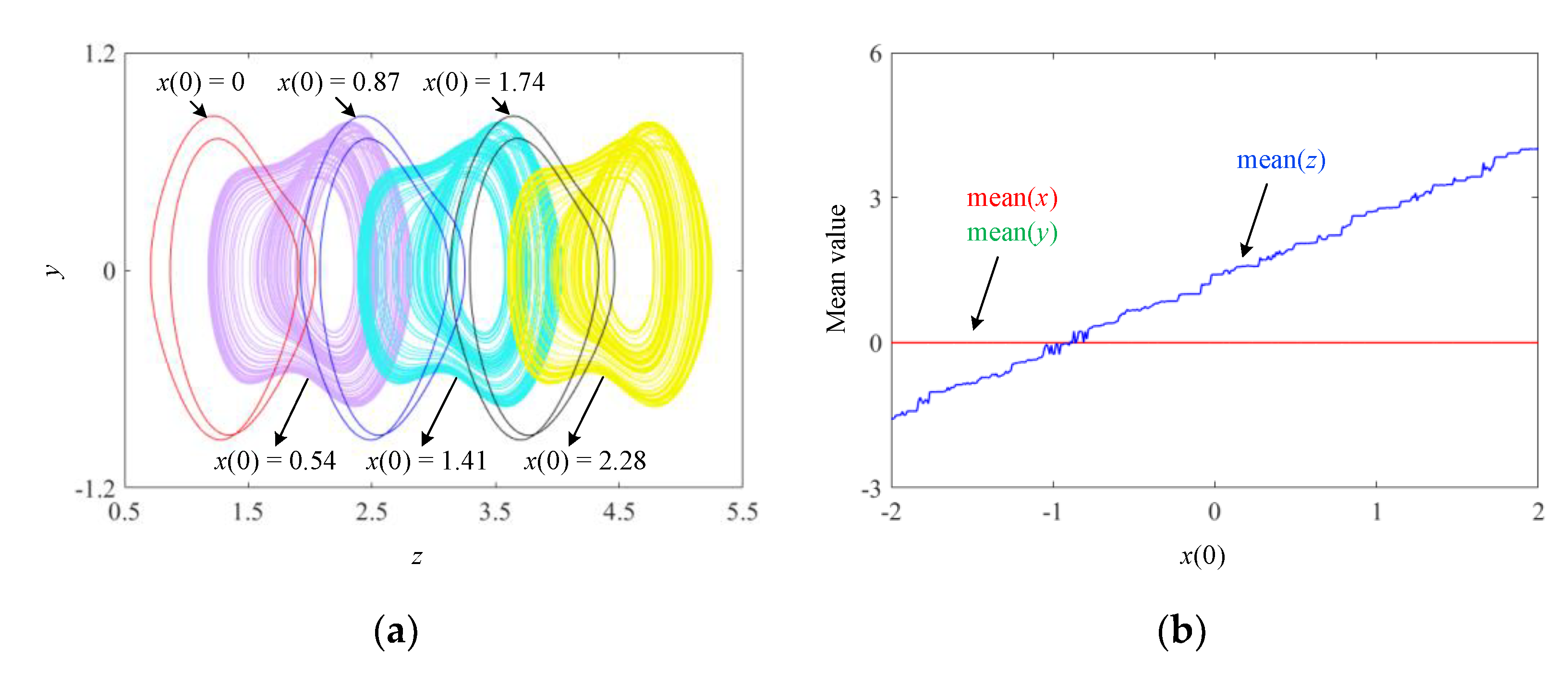
Additionally, initial-condition-dependent boosting behavior is also discovered in System (3). Figure 5 depicts the periodically boosted phase portraits and the mean values of the three state variables with fixed initial conditions y(0) = z(0) = 0. The phase portraits of the coexisting chaotic attractors and periodic limit cycles in three adjacent periods are plotted in Figure 5a. The chaotic attractors for initial condition (0.54, 0, 0), (1.41, 0, 0), and (2.28. 0, 0) are periodically boosted along the z coordinate. Similarly, the periodic limit cycle for the initial condition (0, 0, 0) and its periodically boosted limit cycles along the z coordinate are also illustrated in Figure 5a. The mean values of state variables x, y, and z related to the initial condition (x(0), 0, 0) are depicted in Figure 5b. Mean(x) and mean(y) are equal to 0, while mean(z) increases linearly. Figure 5 shows that the attractors move along the positive direction of the z coordinate as the initial conditions change, indicating that System (3) can trigger the phenomenon of extreme multistability.

3. Dimensionality Reduction Analysis of the Non-Autonomous Memcapacitive System

Because the Jacobian matrix in (6) has one zero root, the stability of the line equilibrium set S cannot be analyzed by the classical linear stability theory. Therefore, the incremental integral method is employed to reconstruct the memcapacitive system. In the reconstructed system, the time evolution of the number and stability of the equilibrium points are figured out. Furthermore, the initial conditions of the original memcapacitive system are mapped onto controlling parameters of the newly reconstructed system. Then, the forming mechanism of the extreme multistability is declared.

3.1. Non-Autonomous Dimensionality Reduction Model and Stability Analysis

The incremental integral method is the extension of incremental integral flux-charge method [38]. Any practical application of a circuit or system actually starts at a finite time instant t0 which represents the instant when switches are turned on or off. Here, we define the time instant t0 = 0. By integrating the equations of the system model from 0 to t, a new dimensionality reduction system can be built. The main advantage of this method is that it makes it possible to simplify the investigation of nonlinear dynamics and bifurcation phenomenon. Furthermore, this method can make clear the influence of initial conditions.
To derive the new dimensionality reduction model of System (3), two variables and three initial-condition-related parameters are defined as
X = 0 t x d τ , Y = 0 t y d τ ,
and
η 1 = x ( 0 ) , η 2 = y ( 0 ) , η 3 = z ( 0 ) .
Here,
X ( 0 ) = 0 0 x d τ = 0 , Y ( 0 ) = 0 0 y d τ = 0 .
Integrating the state equations of System (3) from 0 to t, one gets
0 t x ˙ d τ = k 0 t x d τ k 0 t [ α + β cos ( η z ) ] y d τ + k A 0 t sin ( ϖ τ ) d τ , 0 t y ˙ d τ = 0 t x d τ , 0 t z ˙ d τ = 0 t y d τ .
From the last Equation of (12), we can obtain
z = Y + η 3 .
By substituting (13) into (12), (12) can be rewritten as
x η 1 = k X k 0 t [ α + β cos ( η Y + η η 3 ) ] d Y + k A ϖ k A ϖ cos ( ϖ t ) , y η 2 = X .
Because
0 t cos ( η Y + η η 3 ) d Y = 1 η 0 t cos ( η Y + η η 3 ) d ( η Y + η η 3 ) = 1 η sin ( η Y + η η 3 ) | 0 t = 1 η sin ( η Y + η η 3 ) 1 η sin ( η η 3 ) .
Then, System (3) can be deduced as
X ˙ = k X k α Y k β η sin ( η Y + η η 3 ) k A ϖ cos ( ϖ t ) + k A ϖ + k β η sin ( η η 3 ) + η 1 , Y ˙ = X + η 2 .
The reconstructed System (15) is a two-dimensional (2D) non-autonomous system. The initial conditions of System (3) are explicitly expressed by the initial-condition-related parameters η1, η2, and η3 in System (15). According to (11), the initial conditions of System (15) are all equal to 0. In this case, the reconstructed system can maintain the same dynamics as System (3).
For the reconstructed System (15), the equilibrium state is determined as
E = ( η 2 , Y ˜ ) ,
where is the solution of the following equation
k α Y ˜ k β η sin ( η Y ˜ + η η 3 ) + k β η sin ( η η 3 ) k A ϖ cos ( ϖ t ) + k A ϖ + η 1 + k η 2 = 0 .
It is clear that the roots of Equation (17) keep changing with time and they are related to η1, η2, and η3. The Jacobian matrix JS for System (15) at the equilibrium E is derived as
J S = [ k k α k β cos ( η Y ˜ + η η 3 ) 1 0 ] .
The corresponding eigenpolynomial is deduced as
det ( I λ J ) = λ 2 + a 3 λ + a 4 = 0 ,
where
a 3 = k , a 4 = k α + k β cos ( η Y ˜ + η η 3 ) .
The eigenvalues of Equation (19) depend strongly on the variation of . The variation curves of with time t for different initial-condition-related parameters are plotted in Figure 6a,b. Meanwhile, the stability characteristics of each equilibrium point at the corresponding values are marked by different colors [39]. The curves in blue, magenta, and green represent unstable node-focus (UNF), unstable saddle point (USP), and stable node point (SNP), respectively. The mark “*” denotes the fold bifurcation point (FBP). Assume time t is changing from 0 to 4π/ϖ, i.e., two complete excitation signal cycles. The number of equilibrium points changes between 1 and 3 with variation in time. Meanwhile, the equilibrium stability transmits between stable and unstable points via some fold bifurcation points in one full periodic cycle. For the initial conditions (X(0), Y(0)) = (0, 0), Figure 6c,d show the stability distribution of the equilibrium points and triggered attractors for different initial-condition-related parameters (η1 = 0, η2 = 0, η3 = 0) and (η1 = 0.39, η2 = 0, η3 = 0) in the X−Y plane. These two attractors are constrained around the line segment of the equilibrium points in Figure 6c,d. It is noted that the zero eigenvalue in Equation (7) disappears in Equation (19). This further illustrates that the stability analysis of the non-autonomous memcapacitive oscillator becomes clearer by using the dimensionality reduction model.

3.2. Bifurcation Behaviors Induced by Initial-Condition-Related Parameters

In the reconstructed System (15), the three initial-condition-related parameters η1, η2 and η3 correspond to the three initial conditions x(0), y(0) and z(0) in the original memcapacitive System (3), respectively. With the initial-condition-related parameters η1 and η3 as bifurcation parameters, Figure 7 presents the 1D bifurcation diagrams of state variable X and the first Lyapunov exponent spectrum. Comparing Figure 3 and Figure 7, the reconstructed System (15) reveals the same bifurcation behaviors as System (3) does.
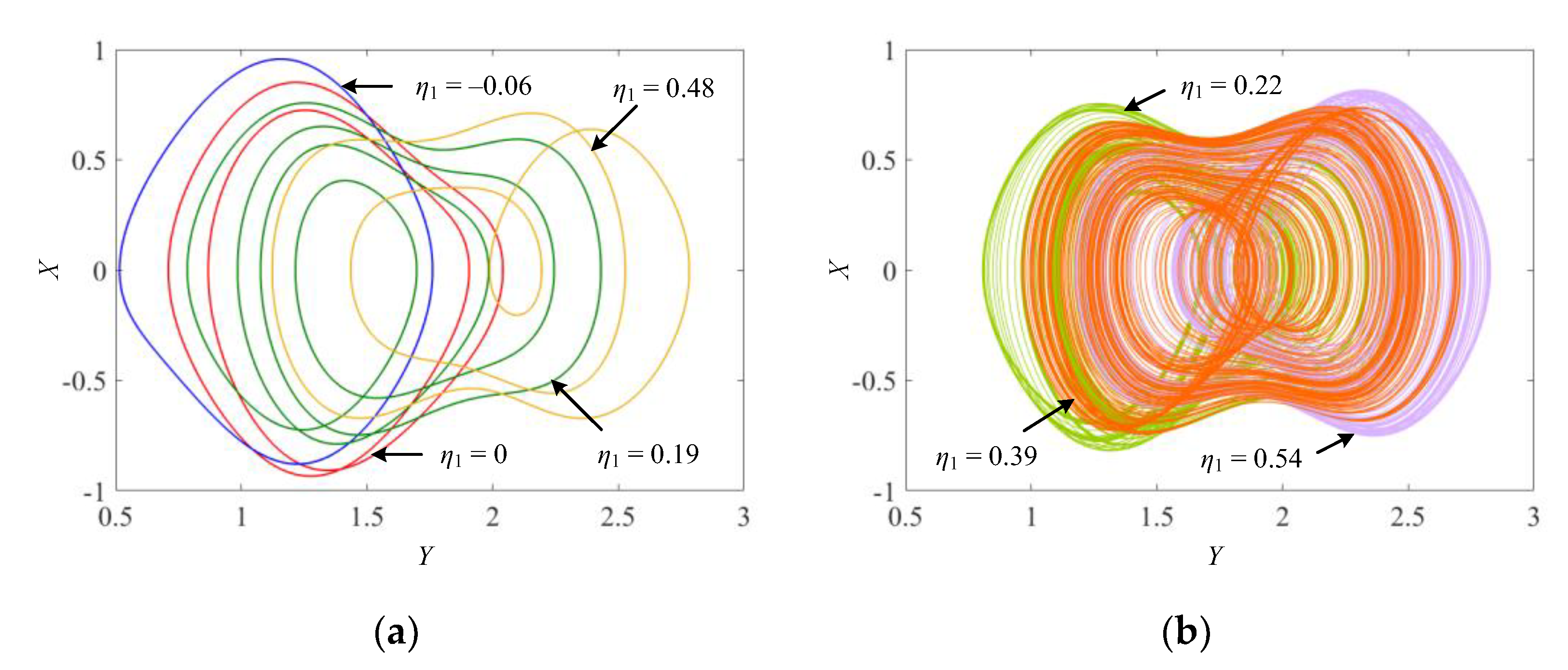
When the values η2 = η3 = 0 are assigned, the reconstructed periodic and chaotic attractors of System (15) are shown in Figure 8. According to the initial conditions employed in Figure 4a, Figure 8a shows four reconstructed periodic limit cycles for η1 = −0.06, 0, 0.19, and 0.48. Meanwhile, corresponding to the chaotic coexisting attractors depicted in Figure 4b, a pair of reconstructed symmetrical chaotic attractors for η1 = 0.22 and 0.54, and a reconstructed double-scroll chaotic attractor for η1 = 0.39 are plotted in Figure 8b. The numerical simulation results in Figure 7 and Figure 8 indicate that the reconstructed System (15) has consistent dynamics with those described in Figure 3 and Figure 4.
The veil of the extreme multistability induced by initial conditions x(0), y(0), and z(0) in the original memcapacitive System (3) can be uncovered in the reconstructed System (15). By the incremental integral transformation, the initial conditions of the original memcapacitive system are mapped onto initial-condition-related parameters η1, η2 and η3 in the newly reconstructed System (15). Thus, the forming mechanism of the extreme multistability is declared and explained by analyzing the dynamics associated with the initial-condition-related parameters.

4. Circuit Simulation for the Reconstructed System

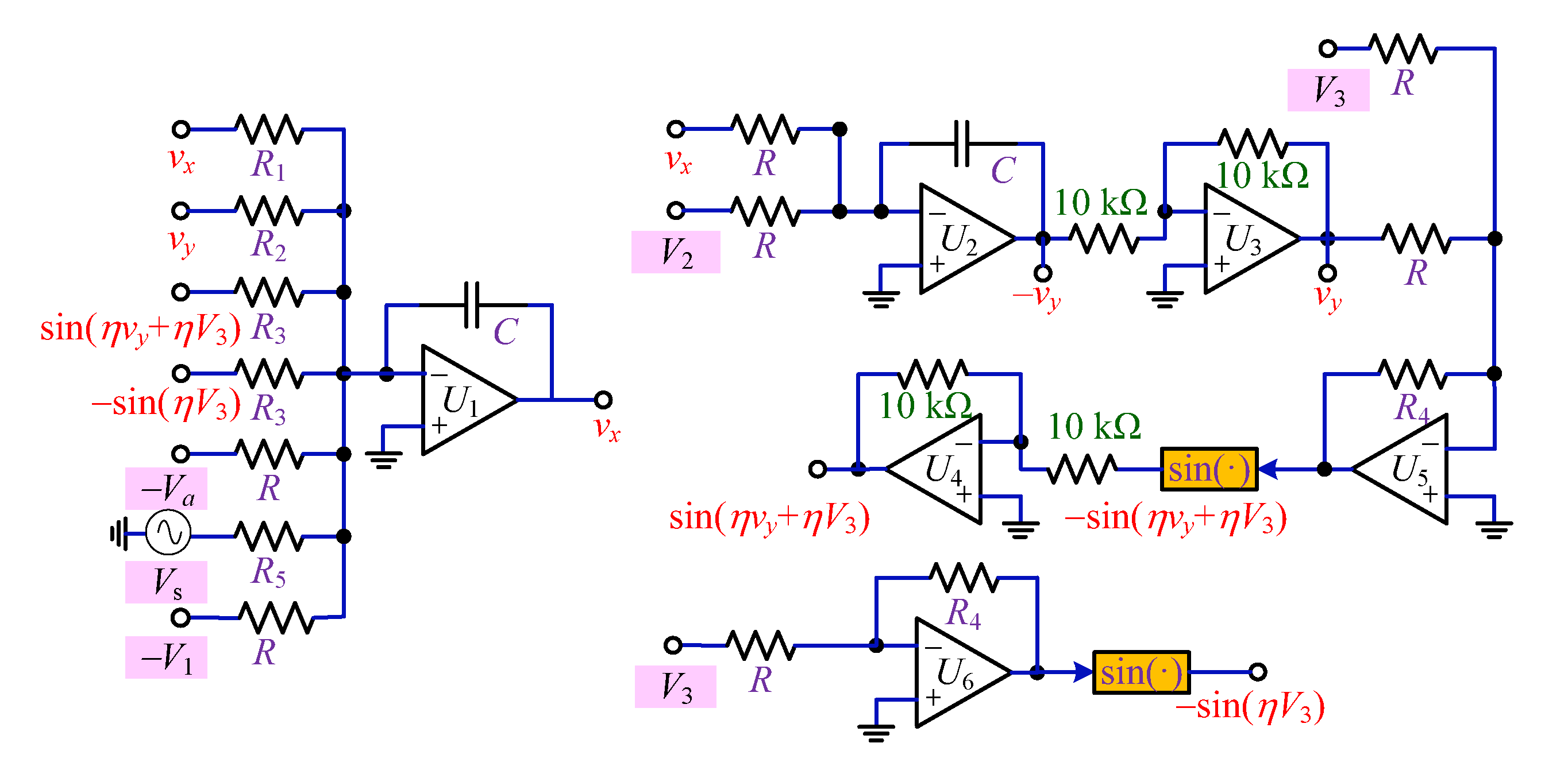
PSIM (power simulation) circuit simulation is a common method to verify numerical analyses [40,41,42]. The implementation circuit of the reconstructed System (15) is presented in Figure 9. This analog circuit is composed of operational amplifiers, trigonometric function converters, resistors, capacitors, DC voltage sources, and a sinusoidal voltage source. Here, the voltage supplies of the operational amplifiers and trigonometric functions converters are ±15 V. The time constant of this circuit is defined as τ = RC = 10 Kω × 100 nF = 1 ms. Then, the other resistors are calculated as R1 = R/k = 9.03 kΩ, R2 = R/() = 13.93 kΩ, R3 = ηR/() = 16.25 kΩ, R4 = ηR = 51.84 kΩ and R5 = /kA = 10.83 kΩ.
Following the implementation circuit in Figure 9, the circuit equations of the reconstructed System (15) are expressed as
R C d v x d t = R R 1 v x R R 2 v y R R 3 sin ( R 4 R v y + R 4 R V 3 ) + R R 3 sin ( R 4 R V 3 ) + R R 5 cos ( ϖ t ) + V 1 + V a , R C d v y d t = v x + V 2 .
Here, vx and vy are two circuit variables corresponding to the state variables X and Y of System (15), three DC voltage biases V1~V3 correspond to the initial-condition-related parameters η1~η3, and a DC voltage bias Va = kA/ϖ is employed. A sinusoidal voltage source Vs = (R/R5)cos(ϖt/RC) V is employed.
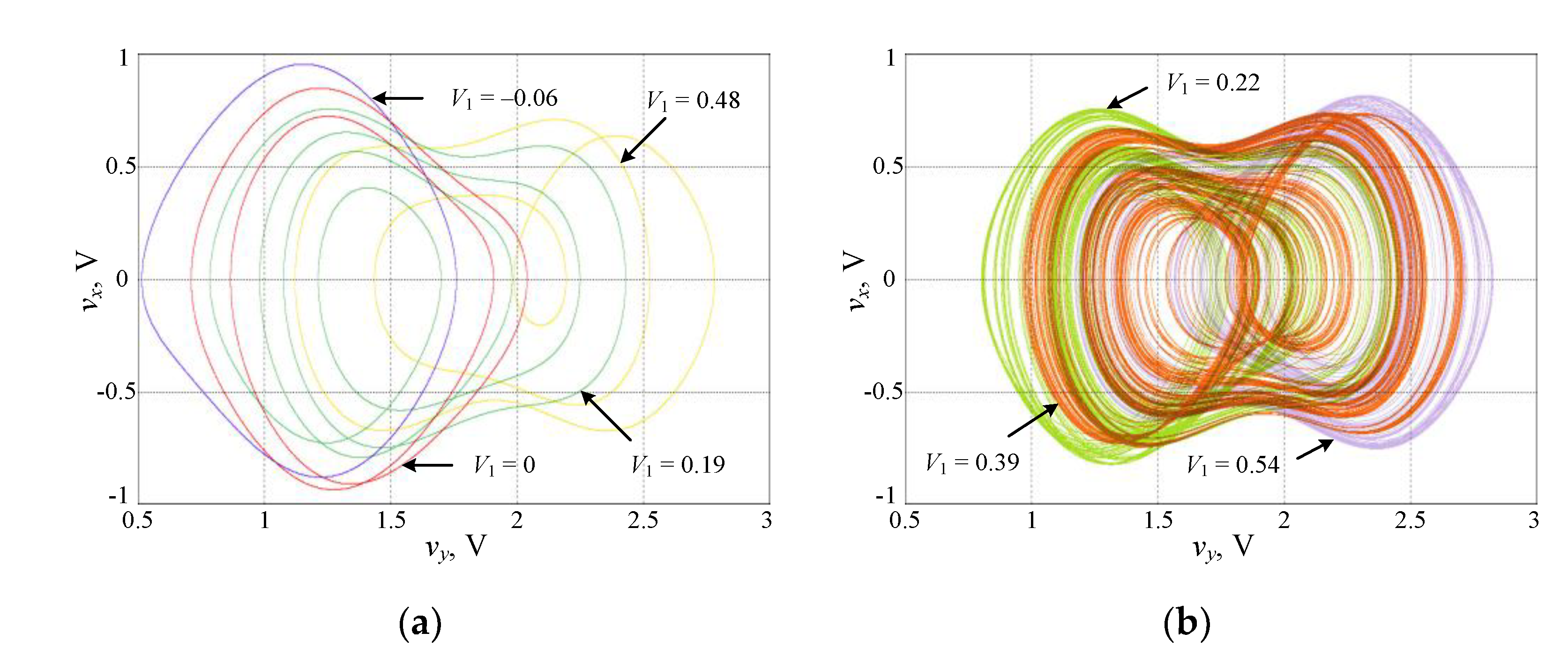
Let V2 = V3 = 0 V, Va = 0.92 V. When the voltage of V1 is set to −0.06 V, 0 V, 0.19 V, and 0.48 V, respectively, the limit cycles with different periodicities are captured in Figure 9a. Then, a pair of symmetrical chaotic attractors and a double-scroll chaotic attractor for V1 = 0.22 V, 0.54 V, and 0.39 V are captured in Figure 10b. The PSIM circuit simulations match well with the MATLAB numerical simulations in Figure 8. These PSIM results for different voltage values of V1~V3 can further confirm the coexistence of infinitely many attractors.

5. Conclusions

In this paper, a simple non-autonomous memcapacitive oscillator was built consisting only of a memcapacitor, a linear resistor, a linear inductor, and a sinusoidal voltage source in series. Intriguingly, the special phenomenon of extreme multistability occurred in this simple memcapacitive circuit. Extreme multistability with the coexistence of infinitely many periodic limit cycles and chaotic attractors was generated in this memcapacitive oscillator, possessing time-varying equilibrium points. The equilibrium points evolved with time between the no equilibrium point and a line equilibrium set. Because of the presence of zero root caused by the line equilibrium set, the equilibrium stability of the memcapacitive system cannot be effectively explained by classical linear stability theory. Thus, a reconstructed system was obtained by the incremental integral method to analyze the stability of the memcapacitive oscillator. The number of its equilibrium points varied with time, and the equilibrium stability changes between stable and unstable via fold bifurcation. Meanwhile, the initial conditions of the original system are explicitly expressed by the initial-condition-related parameters of the reconstructed system. The forming mechanism of initial-condition-dependent extreme multistability was clarified on the basis of an analysis of the dynamical behaviors associated with the initial-condition-related parameters. Circuits or systems that exhibit extreme multistability are usually sensible to noise. In future work, we will analyze the noise effect.

Author Contributions

Conceptualization, B.C. and X.C.; methodology, B.C. and M.C.; software, X.C. and H.B.; validation, M.C. and Q.X.; investigation, B.C. and X.C.; writing—original draft preparation, B.C.; writing—review and editing, Q.X.; supervision, H.B. All authors have read and agreed to the published version of the manuscript.

Funding

This research was funded by the National Natural Science Foundation of China, grant numbers 12172066 and 51777016, the Natural Science Foundation of Jiangsu Province, China, grant numbers BK20210850 and BK20191451, the open research fund of Key Laboratory of MEMS of Ministry of Education, Southeast University, and the Fundamental Research Funds for the Central Universities, under 2242020k30039.

Institutional Review Board Statement

Not applicable.

Informed Consent Statement

Not applicable.

Data Availability Statement

Data generated during the current study will be made available at reasonable request.

Conflicts of Interest

The authors declare no conflict of interest.

References

  1. Chua, L.O. Memristor-The missing circuit element. IEEE Trans. Circuit Theory 1971, 18, 507–519. [Google Scholar] [CrossRef]
  2. Strukov, D.B.; Snider, G.S.; Stewart, D.R.; Williams, R.S. The missing memristor found. Nature 2008, 453, 80–83. [Google Scholar] [CrossRef]
  3. Ya, X.B.; Zhao, J.H.; Sen, L.; Zhou, Z.Y.; Liu, Q.; Chen, J.S.; Liu, X.Y. Memristor with Ag-cluster-doped TiO2 films as artificial synapse for neuroinspired computing. Adv. Func. Mater. 2018, 28, 1705320. [Google Scholar]
  4. Zhang, S.; Luo, S.J.; Xu, N.; Zou, Q.M.; Song, M.; Yun, J.J.; Luo, Q.; Guo, Z.; Li, R.F.; Tian, W.C.; et al. A spin-orbit-torque memristive device. Adv. Electron. Mater. 2019, 5, 1800782. [Google Scholar] [CrossRef]
  5. Zhang, W.; Mazzarello, R.; Wuttig, M.; Ma, E. Designing crystallization in phase-change materials for universal memory and neuro-inspired computing. Nat. Rev. Mater. 2019, 4, 150–168. [Google Scholar] [CrossRef]
  6. Chanthbouala, A.; Garcia, V.; Cherifi, R.O.; Bouzehouane, K.; Fusil, S.; Moya, X.; Xavier, X.; Yamada, H.; Deranlot, C.; Mathur, N.D.; et al. A ferroelectric memristor. Nat. Mater. 2012, 11, 860–864. [Google Scholar] [CrossRef]
  7. Ventra, M.D.; Pershin, Y.V.; Chua, L.O. Circuit elements with memory: Memristors, memcapacitors, and meminductors. Proc. IEEE 2009, 97, 1717–1724. [Google Scholar] [CrossRef] [Green Version]
  8. Demasius, K.; Kirschen, A.; Parkin, S. Energy-efficient memcapacitor devices for neuromorphic computing. Nat. Electron. 2021, 4, 748–756. [Google Scholar] [CrossRef]
  9. Najem, J.S.; Hasan, M.S.; Williams, R.S.; Weiss, R.J.; Rose, G.S.; Taylor, G.J.; Sarles, S.A.; Collier, C.P. Dynamical nonlinear memory capacitance in biomimetic membranes. Nat. Commun. 2019, 10, 3239. [Google Scholar] [CrossRef] [Green Version]
  10. Khan, A.K.; Lee, B.H. Monolayer MoS2 metal insulator transition based memcapacitor modeling with extension to a ternary device. AIP Adv. 2016, 6, 095022. [Google Scholar] [CrossRef] [Green Version]
  11. Kimura, M.; Ishisaki, Y.; Miyabe, Y.; Yoshida, H.; Ogawa, I.; Yokoyama, T.; Haga, K.I.; Tokumitsu, E.; Nakashima, Y. Neuromorphic system using memcapacitors and autonomous local learning. IEEE Trans. Neural Netw. Learn. Syst. 2021. [Google Scholar] [CrossRef]
  12. Sun, J.W.; Han, G.Y.; Wang, Y.F. Dynamical analysis of memcapacitor chaotic system and its image encryption application. Int. J. Control Autom. Syst. 2020, 18, 1242–1249. [Google Scholar] [CrossRef]
  13. Guo, M.; Yang, R.; Zhang, M.; Liu, R.Y.; Zhu, Y.L.; Dou, G. A novel memcapacitor and its application in a chaotic circuit. Nonlinear Dyn. 2021, 105, 877–886. [Google Scholar] [CrossRef]
  14. Chen, B.; Xu, Q.; Chen, M.; Wu, H.G.; Bao, B.C. Initial-condition-switched boosting extreme multistability and mechanism analysis in a memcapacitive oscillator. Front. Inform. Technol. Electron. Eng. 2021, 22, 1517–1531. [Google Scholar] [CrossRef]
  15. Yuan, F.; Li, Y.X. A chaotic circuit constructed by a memristor, a memcapacitor and a meminductor. Chaos 2019, 29, 101101. [Google Scholar] [CrossRef] [PubMed]
  16. Wang, X.Y.; Yu, J.; Jin, C.X.; Iu, H.H.C.; Yu, S.M. Chaotic oscillator based on memcapacitor and meminductor. Nonlinear Dyn. 2019, 96, 161–173. [Google Scholar] [CrossRef]
  17. Zhao, Q.; Wang, C.H.; Zhang, X. A universal emulator for memristor, memcapacitor, and meminductor and its chaotic circuit. Chaos 2019, 29, 013141. [Google Scholar] [CrossRef] [PubMed]
  18. Rajagopal, K.; Jafari, S.; Karthikeyan, A.; Srinivasan, A.; Ayele, B. Hyperchaoticmemcapacitor oscillator with infinite equilibria and coexisting attractors. Circuits Syst. Signal Process. 2018, 37, 3702–3724. [Google Scholar] [CrossRef]
  19. Rajagopal, K.; Karthikeyan, A.; Srinivasan, A. Dynamical analysis and FPGA implementation of a chaotic oscillator with fractional-order memristor components. Nonlinear Dyn. 2018, 91, 1491–1512. [Google Scholar] [CrossRef]
  20. Zhou, W.; Wang, G.Y.; Iu, H.H.C.; Shen, Y.R.; Liang, Y. Complex dynamics of a non-volatile memcapacitor-aided hyperchaotic oscillator. Nonlinear Dyn. 2020, 100, 3937–3957. [Google Scholar] [CrossRef]
  21. Ma, X.J.; Mou, J.; Liu, J.; Ma, C.G.; Yang, F.F.; Zhao, X. A novel simple chaotic circuit based on memristor-memcapacitor. Nonlinear Dyn. 2020, 100, 2859–2876. [Google Scholar] [CrossRef]
  22. Ngonghala, C.N.; Feudel, U.; Showalter, K. Extreme multistability in a chemical model system. Phys. Rev. E 2011, 83, 056206. [Google Scholar] [CrossRef] [PubMed] [Green Version]
  23. Bao, B.C.; Xu, Q.; Bao, H.; Chen, M. Extreme multistability in a memristive circuit. Electron. Lett. 2016, 52, 1008–1009. [Google Scholar] [CrossRef]
  24. Chen, M.; Sun, M.X.; Bao, H.; Hu, Y.H.; Bao, B.C. Flux-charge analysis of two-memristor-based Chua’s circuit: Dimensionality decreasing model for detecting extreme multistability. IEEE Trans. Ind. Electron. 2020, 67, 2197–2206. [Google Scholar] [CrossRef]
  25. Zhang, H.Y.; Sun, K.H.; He, S.B. A fractional-order ship power system with extreme multistability. Nonlinear Dyn. 2021, 106, 1027–1040. [Google Scholar] [CrossRef]
  26. Zhang, L.P.; Liu, Y.; Wei, Z.C.; Jiang, H.B.; Bi, Q.S. A novel class of two-dimensional chaotic maps with infinitely many coexisting attractors. Chin. Phys. B 2020, 29, 060501. [Google Scholar] [CrossRef]
  27. Wu, H.G.; Ye, Y.; Bao, B.C.; Chen, M.; Xu, Q. Memristor initial boosting behaviors in a two-memristor-based hyperchaotic system. Chaos Solit. Fract. 2019, 121, 178–185. [Google Scholar] [CrossRef]
  28. Li, C.B.; Peng, Y.X.; Tao, Z.; Sprott, J.C.; Jafari, S. Coexisting Infinite Equilibria and Chaos. Int. J. Bifurc. Chaos 2021, 31, 2130014. [Google Scholar] [CrossRef]
  29. Bao, H.; Ding, R.Y.; Wu, H.G.; Chen, B. Initial-condition effects on a two-memristor-based Jerk system. Mathematics 2022, 10, 411. [Google Scholar] [CrossRef]
  30. Bao, H.; Chen, M.; Wu, H.G.; Bao, B.C. Memristor initial-boosted coexisting plane bifurcations and its extreme multi-stability reconstitution in two-memristor-based dynamical system. Sci. China Tech. Sci. 2020, 63, 77–87. [Google Scholar] [CrossRef]
  31. Pham, V.T.; Volos, C.K.; Kapitaniak, T.; Jafari, S.; Wang, X. Dynamics and circuit of a chaotic system with a curve of equilibrium points. Int. J. Electron. 2018, 105, 385–397. [Google Scholar] [CrossRef]
  32. Akgul, A.; Kengne, J.; Rajagopal, K.; Pham, V.T.; Varan, M.; Karthikeyan, A.; Guleryuz, E.; Kutlu, M.C. Simulation and experimental implementations of memcapacitor based multi-stable chaotic oscillator and its dynamical analysis. Phys. Scr. 2021, 96, 015209. [Google Scholar] [CrossRef]
  33. Chen, B.; Cheng, X.X.; Wu, H.G.; Bao, B.C.; Xu, Q. Infinitely many necklace-shaped coexisting attractors in a nonautonomous memcapacitive oscillator. Int. J. Bifurc. Chaos 2022, 32, 2250028. [Google Scholar] [CrossRef]
  34. Bao, H.; Liu, W.B.; Chen, M. Hidden extreme multistability and dimensionality reduction analysis for an improved non-autonomous memristiveFitzHugh-Nagumo circuit. Nonlinear Dyn. 2019, 96, 1879–1894. [Google Scholar] [CrossRef]
  35. Chen, M.; Qi, J.W.; Xu, Q.; Bao, B.C. Quasi-period, periodic bursting and bifurcations in memristor-based FitzHugh-Nagumo circuit. Int. J. Electron. Commun. 2019, 110, 152840. [Google Scholar] [CrossRef]
  36. Xu, Q.; Liu, T.; Feng, C.T.; Bao, H.; Wu, H.G.; Bao, B.C. Continuous non-autonomous memristive Rulkov model with extreme multistability. Chin. Phys. B 2021, 30, 128702. [Google Scholar] [CrossRef]
  37. Corinto, F.; Forti, M. Memristor circuits: Bifurcations without parameters. IEEE Trans. Circuits Syst. I Reg. Pap. 2017, 64, 1540–1551. [Google Scholar] [CrossRef]
  38. Corinto, F.; Forti, M. Memristor Circuits: Flux-charge analysis method. IEEE Trans. Circuits Syst. I Reg. Pap. 2016, 63, 1997–2009. [Google Scholar] [CrossRef] [Green Version]
  39. Bao, B.C.; Zhu, Y.X.; Li, C.Q.; Bao, H.; Xu, Q. Global multistability and analog circuit implementation of an adapting synapse-based neuron model. Nonlinear Dyn. 2021, 101, 1105–1118. [Google Scholar] [CrossRef]
  40. Pham, V.T.; Vaidyanathan, S.; Volos, C.K.; Jafari, S.; Kuznetsov, N.V.; Hoang, T.M. A novel memristive time-delay chaotic system without equilibrium points. Eur. Phys. J. Spec. Top. 2016, 225, 127–136. [Google Scholar] [CrossRef]
  41. Xu, Q.; Ju, Z.T.; Ding, S.K.; Feng, C.T.; Chen, M.; Bao, B.C. Electromagnetic induction effects on electrical activity within a memristive Wilson neuron model. Cogn. Neurodyn. 2022. [Google Scholar] [CrossRef]
  42. Pham, V.T.; Jafari, S.; Vaidyanathan, S.; Volos, C.; Wang, X. A novel memristive neural network with hidden attractors and its circuitry implementation. Sci. China Tech. Sci. 2016, 59, 358–363. [Google Scholar] [CrossRef]
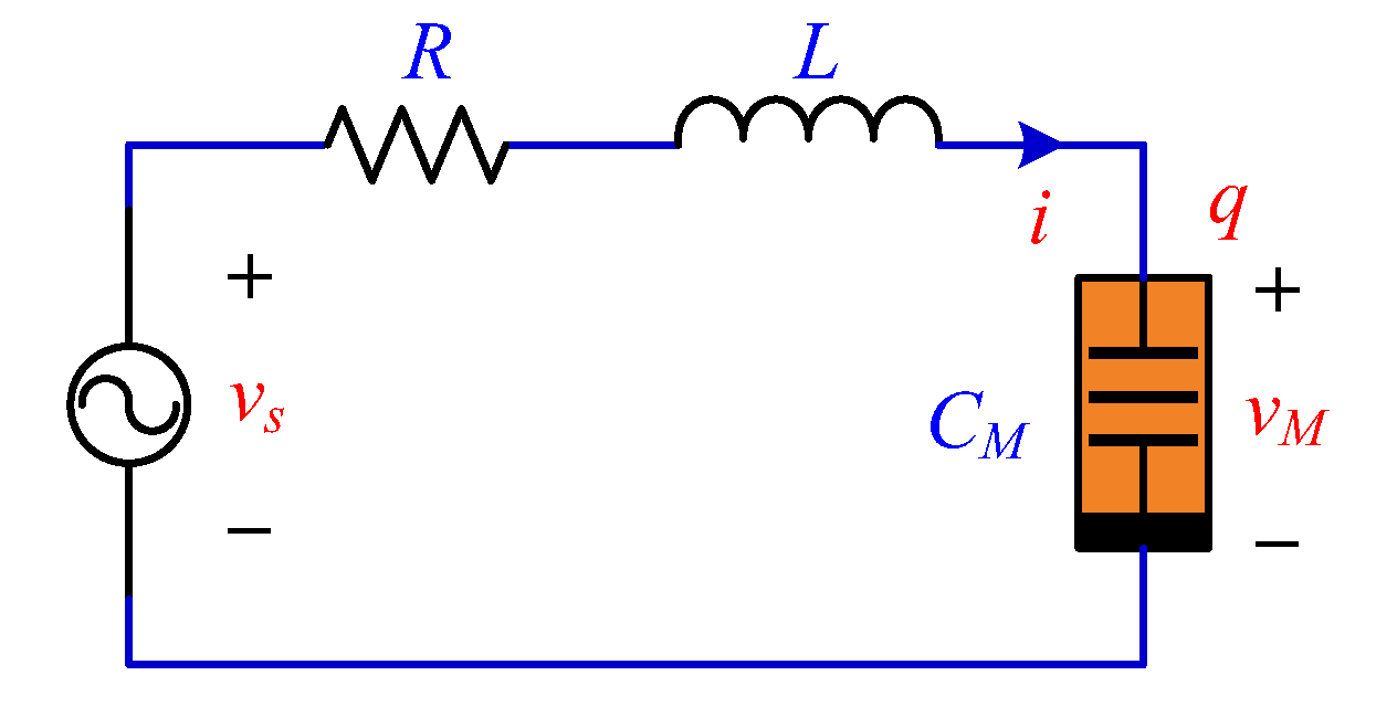
Figure 1. Circuit schematic of the non-autonomous memcapacitive oscillator.
Mathematics 10 00754 g001
Figure 2. Local attraction basin in the x(0)−z(0) initial condition plane and the Period-11 limit cycle: (a) the local attraction basin whose shape is a periodic water ripple pattern with the initial condition y(0) = 0; (b) the phase trajectory and time-domain waveform of a Period-11 limit cycle for the initial condition (−2, 0, −1.025).
Mathematics 10 00754 g002
Figure 3. Bifurcations without parameters and the first Lyapunov exponent spectra: (a) x(0)-related bifurcation and the first Lyapunov exponent spectrum with fixed y(0) = z(0) = 0; (b) z(0)-related bifurcation and the first Lyapunov exponent spectrum with fixed x(0) = y(0) = 0.
Mathematics 10 00754 g003
Figure 4. Initial-condition-dependent phase trajectory: (a) coexisting periodic limit cycles for different initial conditions (−0.06, 0, 0), (0, 0, 0), (0.19, 0, 0), and (0.48, 0, 0); (b) coexisting chaotic attractors for different initial conditions (0.22, 0, 0), (0.39, 0, 0), and (0.54, 0, 0).
Mathematics 10 00754 g004
Figure 5. Initial-condition-dependent boosting behaviors illustrated by periodically boosted phase portraits and the mean values of the three state variables with fixed y(0) = z(0) = 0: (a) chaotic attractors for x(0) = 0.54, 1.41, and 2.28 as well as periodical limit cycles for x(0) = 0, 0.87, 1.74; (b) mean(x) and mean(y) equal to 0, while mean(z) increases linearly with increasing x(0).
Mathematics 10 00754 g005
Figure 6. Evolutions of the distribution and the phase plane plots with the initial condition (X(0), Y(0)) = (0, 0): (a) η1 = 0, η2 = 0, η3 = 0; (b) η1 = 0.39, η2 = 0, η3 = 0; (c) phase plane plots for (η1, η2, η3) = (0, 0, 0); (d) phase plane plots for (η1, η2, η3) = (0.39, 0, 0).
Mathematics 10 00754 g006
Figure 7. Bifurcation diagrams of the state variable X and the first Lyapunov exponent spectra: (a) η1-related bifurcation diagram and the first Lyapunov exponent spectrum with fixed η2 = η3 = 0; (b) η3-related bifurcation diagram and the first Lyapunov exponent spectrum with fixed η1 = η2 =0.
Mathematics 10 00754 g007
Figure 8. Phase plots in Y−X phase plane for different initial-condition-related parameter η1, where η2 = 0 and η3 = 0: (a) four types of periodic limit cycles for η1 = −0.06, 0, 0.19, and 0.48; (b) three types of chaotic attractors for η1 = 0.22, 0.54, and 0.39.
Mathematics 10 00754 g008
Figure 9. Analog circuit implementation circuit for the reconstructed System (15).
Mathematics 10 00754 g009
Figure 10. PSIM results of phase plane plots in vyvx for different initial voltage V1, where V2 = 0 and V3 = 0: (a) four types of periodic limit cycles for V1 = −0.06 V, 0 V, 0.19 V, and 0.48 V; (b) three types of chaotic attractors for V1 = 0.22 V, 0.54 V, 0.39 V.
Mathematics 10 00754 g010
Publisher’s Note: MDPI stays neutral with regard to jurisdictional claims in published maps and institutional affiliations.