Article

Exact Analytical H-BER for Ad Hoc XOR H-Map Detector for Two Differentially Modulated BPSK Sources in H-MAC Channel

Department of Radio Engineering, Faculty of Electrical Engineering, Czech Technical University in Prague, Technicka 2, 166 27 Prague, Czech Republic
*
Author to whom correspondence should be addressed.
Mathematics 2022, 10(6), 903; https://doi.org/10.3390/math10060903
Submission received: 17 January 2022 / Revised: 8 March 2022 / Accepted: 9 March 2022 / Published: 11 March 2022

Abstract

:
In the article, we present an ad hoc (AH) detector for two differentially encoded BPSK sources in the Hierarchical MAC (H-MAC), i.e., for the case when the receiver sees the superposition of non-orthogonal signals from individual sources. (Prefix “H-” means Hierarchical, it emphasizes that the entity is related to the many-to-one principle.) The AH detector decodes the XOR H-map of the two BPSK streams—in other words, it decides whether the transmitted symbols from the two sources are the same or opposite. The BER of the detection in H-MAC is denoted as H-BER. The H-BER is compared with the other two differential detectors, with the coherent (Coh) detector, and with an approximate coherent (ApC) detector. The exact analytical H-BER formula is derived for the ad hoc and coherent detectors. The proposed ad hoc detector is very simple for evaluation, does not require the estimation of subchannel phases, does not depend on noise variance, and it is uniformly only roughly 3.5 dB worse than the coherent one.
MSC:
94A13

1. Introduction

The two-way relay channel (TWRC) with one relay and two BPSK/PSK sources is a well-studied network. In the standard four-phase communication protocol, the first source transmits to the relay, then the relay resends the data to the second source. The same occurs in the opposite direction—the second source sends its data to the relay, and the relay again retransmits its data to the first source. The four-phase protocol can be reduced to the three-phase protocol by the application of network coding [1]—the relay collects data from both sources, computes a network function, and broadcasts the output back to the sources. Each source can then compute the data of the other source. In the most simple case, the relay computes the XOR of the source messages. Wireless networks allow further reduction of the number of phases—a two-phase protocol can be established. Both sources can transmit simultaneously to the relay. There are two main relay strategies: (1) Amplify and Forward (AF)—the relay simply retransmits the signal it receives without decoding anything; (2) Hierarchical Decode and Forward (HDF)—the relay decodes the XOR of the source symbols directly from the non-orthogonal superposition of source signals, and forwards this “XOR frame”. HDF is also called Denoise and Forward by some authors. Network coding applied in wireless networks, specifically on their physical layer, is often called Physical Layer Network Coding (PLNC) or Wireless Physical Layer Network Coding (WPNC). Details on WPNC can be found in the book [2]. The key idea is to let sources transmit at the same frequency and time, and so save communication resources. Even though the relay cannot separate the interfering signals (by linear methods), it can decode the network function—the XOR of source symbols. The critical phase, when sources transmit at the same frequency and time to the relay, is called Hierarchical MAC (H-MAC). Our work focuses on the transmission and detection in H-MAC. The performance of coherent PLNC schemes is critically dependent on precise channel estimation. We use the differential modulation to compensate for the need to know subchannel phases, i.e., to know complete channel state information (CSI) at the relay node. We consider the detector at the relay to be “differential” to emphasize the fact that the sources are differentially encoded, i.e., that it uses two subsequent channel observations.

2. Related Works

The AF relay strategy is mainly analyzed in other works. In [3], Song et al. analyze differential BPSK in TWRC with the AF relay strategy in Rayleigh fading channels. The differential method is only 3 dB worse than the coherent method. The same scenario, but with multiple relays, is analyzed by Song et al. in [4]—again, the differential method is 3 dB worse than the coherent case. In [5], Xu et al. investigate both AF and HDF with differential modulation for TWRC with multiple relays and MIMO systems. Kanthimatchi and Amutha in [6] introduce generalized differential amplitude-phase modulation for TWRC, and the AF relay strategy is assumed.
In [7], Ju and Kim derived tight upper and lower bounds for H-BER, Huang and Yuan in [8] studied the TWRC with multiple antennas, both papers studied coherent detection with the HDF relay strategy. The HDF relay strategy with differential BPSK/PSK is studied in [9] by Guan and Liu. They derived the covariance matrix of the two-point observation where the mean is over subchannel phases and noise. Subsequently, they approximated the joint distribution of the two-point observation by the joint complex normal (JCN) distribution with this covariance matrix. The detector is used with energy harvesting schemes in [10]. The work of Guan and Liu is extended by Fan et al. in [11] to 4 and 8PSK alphabets, a bitwise-XOR H-map, but the error performance is poor. Another approach is used in [12], where the authors used the product of subsequent observations, as an analogy with one-to-one transmission and reception. In [13], Hron and Sykora derived a closed-form detector that does not need the knowledge of subchannel phases. The joint pdf of observation is marginalized by the maximum over subchannel phases (joint maximum likelihood, JML). The performance is only approximately 3 dB worse than the coherent case.
The paper is organized as follows. In Section 3, the system model for both coherent detection and differential detection in H-MAC is given. The ad hoc detector is presented. Moreover, the coherent detector and its high SNR approximation are given. In Section 4, we present analytical formulae for H-BER of the AH detector and coherent detectors, and we compare our differential AH detector with JML from [13] and JCN from [9]. Further, we present other numerical results such as decision regions and H-BER figures. In Section 5, we conclude the paper.
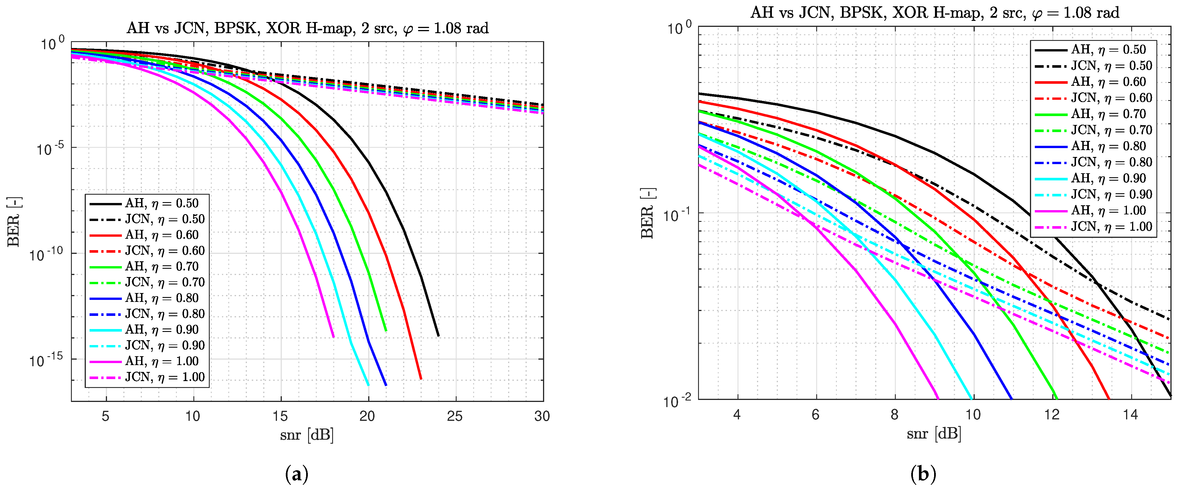
The key contribution of the paper is the proposition of the differential ad hoc (AH) detector of the XOR of source symbols. Sources use differential BPSK (DBPSK) modulation. The AH detector uses two subsequent observations together with the knowledge of the magnitudes of subchannel attenuations, i.e., the minimum of them. The loss of the proposed ad hoc (AH) detector in the error rate is 0.5 dB with regard to the JML and 3.5 dB with regard to the coherent detector. AH is slightly worse than JCN for low SNRs, where H-BER of both detectors is approximately 10 2 , but AH substantially outperforms JCN for higher SNRs.

3. Materials and Methods

The section starts with stating system models of reception in H-MAC. System models for both uncoded BPSK sources and differentially modulated/encoded BPSK sources are given. For H-MAC with uncoded BPSK sources, we recall the coherent detector (Coh) of the XOR H-map. Additionally, a very good approximation of the Coh detector is given—it is denoted as the approximate coherent (ApC) detector. Further, for H-MAC with differentially modulated BPSK sources, an ad hoc detector of the XOR H-map is derived. It uses two subsequent observations. Finally, a general expression for H-BER is shown.
The system model with uncoded BPSK sources is given as
y n = η 1 e j φ 1 d n ( 1 ) + η 2 e j φ 2 d n ( 2 ) + w n .
It is depicted in Figure 1.
In Equation (1), d n ( 1 ) , d n ( 2 ) are uncoded n-th BPSK symbols. η 1 , η 2 and φ 1 , φ 2 are magnitudes and phases of subchannel attenuations, respectively. Index 1 and 2 indicate the source. w n C N ( 0 , σ w 2 ) is the complex Gaussian noise with mean 0 and variance σ w 2 .
The H-MAC system model for the differentially encoded BPSK (DBPSK) sources is given as
y n = η 1 e j φ 1 q n ( 1 ) + η 2 e j φ 2 q n ( 2 ) + w n .
The communication system is illustrated in Figure 2.
Differential BPSK modulation is given as
q n ( i ) = q n 1 ( i ) d n ( i ) , q 0 ( i ) = 1 , i 1 , 2 .
d n ( 1 ) , d n ( 2 ) are uncoded BPSK symbols; q n ( 1 ) , q n ( 2 ) are differentially encoded BPSK symbols. Other variables in (2) are the same as in (1).
The ad hoc detector will use two subsequent observations of the H-MAC channel with DBPSK sources. The two-point observation is
y 0 = η 1 e j φ 1 q 0 ( 1 ) + η 2 e j φ 2 q 0 ( 2 ) + w 0 ,
y 1 = η 1 e j φ 1 q 0 ( 1 ) d 1 ( 1 ) + η 2 e j φ 2 q 0 ( 2 ) d 1 ( 2 ) + w 1 .
In the Equations (4) and (5), we will use the following substitutions:
u A = η 1 e j φ 1 q 0 ( 1 ) = η 1 e j φ 1 , α 1 = φ 1 + arg ( q 0 ( 1 ) ) .
u B = η 2 e j φ 2 q 0 ( 2 ) = η 2 e j φ 2 , α 2 = φ 2 + arg ( q 0 ( 2 ) ) .
However, for simplicity of notation, we will omit 1 index in d 1 ( 1 ) , d 1 ( 2 ) , and obtain
y 0 = u A + u B + w 0 , y 1 = u A d ( 1 ) + u B d ( 2 ) + w 1 .
Now, we recall the coherent detector. It uses one observation from H-MAC with uncoded BPSK (1). The channel likelihood function conditioned by the source BPSK symbols and the one conditioned by the H-symbol b is given as
p ( y | d ( 1 ) , d ( 2 ) ) = exp 1 σ w 2 | y u ( d ( 1 ) , d ( 2 ) ) | 2 ,
p ( y | b ) = 1 2 [ d ( 1 ) , d ( 2 ) ] : b = xor ( d ( 1 ) , d ( 2 ) ) p ( y | d ( 1 ) , d ( 2 ) ) ,
where (for notation simplicity, we have omitted lower time-index n) the useful signal u is
u ( d ( 1 ) , d ( 2 ) ) = η 1 e j φ 1 d ( 1 ) + η 2 e j φ 2 d ( 2 ) .
We recall that the H-symbol b is the output of the H-map. In our case, b = xor ( b ( 1 ) , b ( 2 ) ) xor ( d ( 1 ) , d ( 2 ) ) . The coherent detector of the XOR H-map is derived from the likelihood test
p ( y | b = 0 ) b ^ = 0 b = 1 p ( y | b = 1 ) ,
e 1 σ w 2 | y u ( 1 , 1 ) | 2 + e 1 σ w 2 | y u ( 1 , 1 ) | 2 b ^ = 0 b ^ = 1 e 1 σ w 2 | y u ( 1 , 1 ) | 2 + e 1 σ w 2 | y u ( 1 , 1 ) | 2 .
We obtain the coherent detector of the form
M Coh = cosh 2 σ w 2 { y * ( η 1 e j φ 1 + η 2 e j φ 2 ) } cosh 2 σ w 2 { y * ( η 1 e j φ 1 η 2 e j φ 2 ) } ,
M Coh b ^ = 0 b ^ = 1 exp 4 η 1 η 2 σ w 2 cos ( φ ) .
In the Equation (15), φ = φ 1 φ 2 . In addition, b ^ is the estimated H-symbol.
For the derivation of the approximate coherent detector, we use the following substitutions:
a = { y * ( η 1 e j φ 1 + η 2 e j φ 2 ) } ,
b = { y * ( η 1 e j φ 1 η 2 e j φ 2 ) } .
The derivation follows.
cosh 2 σ w 2 a cosh 2 σ w 2 b = e 2 σ w 2 | a | + e 2 σ w 2 | a | e 2 σ w 2 | b | + e 2 σ w 2 | b | = e 2 σ w 2 ( | a | | b | ) 1 + e 4 σ w 2 | a | 1 + e 4 σ w 2 | b | Q b ^ = 0 b ^ = 1 e 4 σ w 2 η 1 η 2 cos ( φ ) ,
| a | | b | + σ w 2 2 ln ( Q ) b ^ = 0 b ^ = 1 2 η 1 η 2 cos ( φ ) .
We obtain criterion (19) from (18) by applying 2 2 ln ( . ) to both sides of (18). In the expressions (18) and (19),
Q 1 2 , 2 ,
ln ( Q ) ( ln ( 2 ) , ln ( 2 ) ) ( 0.7 , 0.7 ) .
Finally, after resubstitution (16) and (17) to the (19), we obtain the approximate detector of the form
M ApC = | { y * ( η 1 e j φ 1 + η 2 e j φ 2 ) } | | { y * ( η 1 e j φ 1 η 2 e j φ 2 ) } | ,
M ApC b ^ = 0 b ^ = 1 2 η 1 η 2 cos ( φ ) .
The approximation is based on the omission of the expression σ w 2 2 ln ( Q ) from (19). It is close to zero for higher SNR.
Now, we derive an ad hoc differential detector. Assume the H-MAC channel with DBPSK sources, given by the channel model (2). In the derivation of the ad hoc detector, we take the two-point observation (8), and assume a no-noise case. Thus, y 0 = u A + u B , y 1 = u A d ( 1 ) + u B d ( 2 ) . We define two auxiliary sets, B 0 = { u A + u B , u A u B } and B 1 = { u A u B , u A + u B } . The sets are composed to correspond to H-symbols b = 0 and b = 1 , respectively. The detector has to decide whether y 1 B 0 or y 1 B 1 . It will choose the set ( B 0 or B 1 , i.e., the H-symbol b = 0 or b = 1 ) to which y 1 is closer. We use the Euclidean distance. The distance to the B 0 can be computed directly, because B 0 = { y 0 , y 0 } , and y 0 is known. Thus, the detector metric is
M AdH = min { | y 1 y 0 | , | y 1 + y 0 | } .
The decision threshold is selected to be the mid-value between the case y 1 B 0 , i.e., M AdH = 0 , and the case y 1 B 1 , i.e., M AdH = 2 min { | u A | , | u B | } = 2 min { η 1 , η 2 } , as can be seen from Table 1.
Thus,
M AdH b ^ = 1 b ^ = 0 min { η 1 , η 2 } .
In the criterion (25), we will use the shortcut η min = min { η 1 , η 2 } .
To gain insight into what other differential detectors look like, we will proceed as in [13]. The parts of two-point observation y 0 , y 1 are independent complex Gaussian distributed given η 1 , η 2 , φ 1 , φ 2 , d ( 1 ) , d ( 1 ) . We assign η = [ η 1 , η 2 ] , φ = [ φ 1 , φ 2 ] . Single and joint likelihood of observations is, respectively,
p ( y 0 | η , φ ) = 1 π σ w 2 exp 1 σ w 2 | y 0 ( η 1 e j φ 1 + η 1 e j φ 2 ) | 2 ,
p ( y 1 | d ( 1 ) , d ( 2 ) , η , φ ) = 1 π σ w 2 exp 1 σ w 2 | y 1 ( η 1 e j φ 1 d ( 1 ) + η 1 e j φ 2 d ( 2 ) ) | 2 ,
p ( y 0 , y 1 | d ( 1 ) , d ( 2 ) , η , φ ) = p ( y 0 | η , φ ) p ( y 1 | d ( 1 ) , d ( 2 ) , η , φ ) .
The joint pdf (Probability Density Function) of the two-point observation given H-symbol (Hierarchical symbol) b is
p ( y 0 , y 1 | b = 0 , η , φ ) = 1 2 p ( y 0 , y 1 | 1 , 1 , η , φ ) + p ( y 0 , y 1 | 1 , 1 , η , φ ) .
p ( y 0 , y 1 | b = 1 , η , φ ) = 1 2 p ( y 0 , y 1 | 1 , 1 , η , φ ) + p ( y 0 , y 1 | 1 , 1 , η , φ ) .
The detector decides according to the ML (maximum likelihood) criterion
p ( y 0 , y 1 | b = 0 , η , φ ) b ^ = 0 b ^ = 1 p ( y 0 , y 1 | b = 1 , η , φ ) .
The criterion (31) can be simplified to the form
exp 2 σ w 2 { ( η 1 e j φ 1 + η 2 e j φ 2 ) y + * } + exp 2 σ w 2 { ( η 1 e j φ 1 + η 2 e j φ 2 ) y * } · exp 4 σ w 2 η 1 η 2 cos ( φ 1 φ 2 ) [ exp 2 σ w 2 { η 1 e j φ 1 y + * + η 2 e j φ 2 y * } + exp 2 σ w 2 { η 1 e j φ 1 y * + η 2 e j φ 2 y + * } ] b ^ = 0 b ^ = 1 0 ,
where = y 0 + y 1 and = y 0 y 1 . Upper index * means a complex conjugate. We can marginalize the (32) criterion by taking the maximum over [ φ 1 , φ 2 ] ( 0 , 2 π ) 2 , as was done in [13], or by integration. However, in all types of marginalization over phases [ φ 1 , φ 2 ] , the resulting detector should be a function of the sum and the difference of subsequent observations. This is also true of our ad hoc case.

H-BER Formula Derivation

In this subsection, we derive a general expression for the H-BER of a detector of the XOR H-map of two BPSK sources. The detector metric will be called M—it is a function of observation(s). Denote by a the decision threshold. We assume the detector to be of the form
M b ^ = 0 b ^ = 1 a .
Next, the probability of the symbol error Pe = H-BER is derived.
P e = Pr { b ^ b } = Pr { b ^ = 0 , b = 1 } + Pr { b ^ = 1 , b = 0 } , = 1 2 [ Pr { b ^ = 0 | b = 1 } + Pr { b ^ = 1 | b = 0 } ] , = 1 4 [ Pr { b ^ = 0 | A 2 } + Pr { b ^ = 0 | A 3 } + Pr { b ^ = 1 | A 1 } + Pr { b ^ = 1 | A 4 } ] , = 1 4 2 + x a [ p M ( x | A 1 ) + p M ( x | A 4 ) ( p M ( x | A 2 ) + p M ( x | A 3 ) ) ] d x ,
where p M ( x | A i ) is the pdf (Probability Density Function) of M, given event A i . The events are defined in Table 1.

4. Results

In this section, we first show the derived H-BER formulae. The key is to derive the pdf of the detector metric, which is then submitted to Equation (34). Channel observations are taken as random variables (RVs) and detector metrics are functions of observations—functions of RVs. We use standard procedures from the book [14] to derive the pdf of the transformed RVs. Subsequently, we show H-BER of detectors in figures. Details of the derivation can be found in Appendix B. Gaussian RVs (random variables) are recalled in Appendix A. Other supplementary operations with RVs are in Appendix C.

4.1. Analytical H-BER Formula for Ad Hoc (AH) Differential Detector

p M AdH can be derived to be
p M ( x | A i ) = p | Y 0 + Y 1 | ( x | A i ) ( 1 F | Y 0 Y 1 | ( x | A i ) ) + p | Y 0 Y 1 | ( x | A i ) ( 1 F | Y 0 + Y 1 | ( x | A i ) ) ,
where p | Y 0 ± Y 1 | and F | Y 0 ± Y 1 | ( x | A i ) is the pdf and cdf (Cumulative Density Function) of Rice distribution, respectively,
p | Y 0 ± Y 1 | ( x | A i ) p ( x | ν , σ ) , = x σ 2 exp ( x 2 + ν 2 ) 2 σ 2 I 0 x ν σ 2 .
In the expression (36), ν = | u A ( 1 ± d ( 1 ) ) + u B ( 1 ± d ( 2 ) ) | , σ = σ w . Then,
P e = 1 2 + 1 4 0 η min [ p M AdH ( x | A 2 ) + p M AdH ( x | A 3 ) p M AdH ( x | A 1 ) p M AdH ( x | A 4 ) ] d x , = 1 2 + 1 2 0 η min [ p ( x | 2 η 1 , σ w ) Q 1 2 η 2 σ w , x σ w + p ( x | 2 η 2 , σ w ) Q 1 2 η 1 σ w , x σ w
[ p ( x | 2 | u A + u B | , σ w ) Q 1 0 , x σ w + p ( x | 0 , σ w ) Q 1 2 | u A + u B | σ w , x σ w ] ] d x ,
where Q 1 is the Marcum Q-function and
p ( x | 2 | u A + u B | , σ w ) = 1 2 p ( x | 2 | η 1 + η 2 e j φ | σ w , ) + p ( x | | η 1 η 2 e j φ | , σ w ) . Q 1 ( 2 | u A + u B | σ w , x σ w ) = 1 2 ( Q 1 2 | η 1 + η 2 e j φ | σ w , x σ w
+ Q 1 2 | η 1 η 2 e j φ | σ w , x σ w ) .
Again, we have used φ = φ 2 φ 1 .

4.2. Analytical H-BER Formula for Coherent Detector (Coh)

To express p M Coh (pdf of M given in (14)) it is useful to define some auxiliary variables. The detector’s decision-threshold is
a Coh = exp 4 η 1 η 2 cos ( φ ) σ w 2 .
Define (complex valued constant)
c = η 1 e j φ 1 η 2 e j φ 2 η 1 e j φ 1 + η 2 e j φ 2 , c re = { c } , c im = { c } .
Let a joint probability p U , V ( x re , y re ) , x re , y re be
p U , V ( x re , y re ) = 1 π σ 1 2 | c im | exp 1 σ 1 2 ( x re y re ) 2 + x re c re y re c im μ im 2 , for c im 0 .
p U , V ( x re , y re ) = 1 π σ 1 2 exp 1 σ 1 2 ( x re μ re ) 2 δ ( y re x re c re ) , for c im = 0 .
In Equations (43) and (44),
σ 1 2 = 4 σ w 2 | η 1 + η 2 e j φ | 2 ,
μ = ( η 1 d ( 1 ) + η 2 e j φ d ( 2 ) ) 2 σ w 2 ( η 1 + η 2 e j φ ) ,
and δ is the Dirac-delta function. Let the joint probability p W , X ( s , t ) , s , t 1 be
p W , X ( s , t ) = 1 s 2 1 t 2 1 [ p U , V ( + ln ( s + s 2 1 ) , + ln ( t + t 2 1 ) ) + + p U , V ( + ln ( s + s 2 1 ) , ln ( t + t 2 1 ) ) + p U , V ( ln ( s + s 2 1 ) , + ln ( t + t 2 1 ) ) + p U , V ( ln ( s + s 2 1 ) , ln ( t + t 2 1 ) ) ] .
Finally,
p M Coh ( z ) = max { 1 / z , 1 } q p W , X ( z q , q ) d q .
P e = 1 2 + 1 4 0 a Coh [ p M Coh ( z | A 1 ) + p M Coh ( z | A 4 ) p M Coh ( z | A 2 ) p M Coh ( z | A 3 ) ] d z .
In (48), we can use the substitution (50). The 2D integral is then more numerically stable.
Θ ( y x ) = ( cosh ( y ) cosh ( x ) cosh ( y ) ) = ( q z ) .

4.3. Analytical H-BER Formula for Approximate Coherent (ApC) Detector

Again, it is practical to define a few auxiliary definitions. The detector’s decision threshold is
a ApC = 2 η 1 η 2 cos ( φ ) .
The constant c is defined in the same way as in (42). p U , V is formally the same as p U , V in (43) and (44), but
σ 1 2 = | η 1 + η 2 e j φ | 2 σ w 2 ,
μ = ( η 1 d ( 1 ) + η 2 e j φ d ( 2 ) ) ( η 1 + η 2 e j φ ) .
We define the joint pdf p W , X as
p W , X ( x , y ) = p U , V ( x , y ) + p U , V ( x , y ) + p U , V ( x , y ) + p U , V ( x , y ) , x , y 0 .
Finally, p M ApC ( z ) and Pe are
p M ApC ( z ) = max { 0 , z } p W , X ( z + x , x ) d x ,
P e = 1 2 + 1 4 a ApC [ p M ApC ( y | A 1 ) + p M ApC ( y | A 4 ) p M ApC ( y | A 2 ) p M ApC ( y | A 3 ) ] d y .

4.4. Comparison of AH Differential Detector with Other Two Differential Detectors

In this subsection, we compare the H-BER performance of the ad hoc (AH) detector with the joint complex normal (JCN) detector from [9] and with the joint maximum likelihood (JML) detector from [13]. In the referenced figures, we use η = η 2 / η 1 = η min and φ = φ 2 φ 1 . In Figure 3, we see the H-BER of the AH and the JCN detector. The right-hand figure zooms into the lower SNRs. It is clearly visible that for low SNRs, JCN is slightly better than AH (the error rate is of order 10 2 for both detectors), but for high SNRs, AH is remarkably better. In Figure 4, we compare H-BER of the AH and JML detector. Again, the right-hand figure zooms into lower SNRs. Apparently, the loss of AH w.r.t. the JML is about 0.5 dB in H-BER.

4.5. Other Numerical Results

In this subsection, we present the following.
1.
Decision regions for coherent and differential detectors.
2.
Comparison of H-BER performance of coherent vs. approximate coherent detector and coherent vs. ad hoc detector.
3.
H-BER performance of the ad hoc differential detector vs. the approximate coherent detector for the Rayleigh channel.
In all the figures, η 1 = 1 , η 2 = η , φ = φ 2 φ 1 . SNR is given with regard to the first source. Rayleigh fading channel is of the form
y = h 1 q ( 1 ) + η h 2 q ( 2 ) + w ,
where h 1 , h 2 ( 0 , σ 2 ) . σ is chosen to be 2 / 2 so that E [ | h i | 2 ] = 1 . Moreover, the channel attenuation coefficients h 1 , h 2 are assumed to be the same for two consecutive observations. The channel parameter η is fixed for the whole frame and it is the only parameter known to the AH detector in the channel model (57).
Observations follow. In Figure 5a, we see that the boundaries of decision regions of the coherent and the approximate coherent detector for SNR = 0 dB are quite close to each other. For higher SNR, boundaries are closer to each other. That results in practically the same H-BER performance of the two detectors as can be seen in Figure 6a. We can notice that the boundaries of decision regions for the approximate coherent detector consist of 4 line segments.
Decision regions for the ad hoc differential detector are 4-D subsets of 4 . In Figure 5b, we have depicted decision regions for y 1 , given fixed y 0 . Decision regions of the JML detector are also shown. Here we have also shown the decision region for the detector that we get by marginalization of the criterion (32) by integration over [ φ 1 , φ 2 ] ( 0 , 2 π ) 2 . The differential detector is denoted as JML2.
From Figure 6b, we conclude that the H-BER loss of the ad hoc detector w.r.t. the Coh detector is about 3.5 dB.
H-BER does change with φ in Figure 3, Figure 4 and Figure 6a,b by just a fraction of dB.
In Figure 7, we compare the ApC and AH detector for the Rayleigh channel. The AH detector knows only the channel parameter η , as given in the system model (57). We see that the knowledge of the magnitudes of subchannel attenuations for the AH detector is crucial and its absence results in very poor error performance. The ApC detector uses full knowledge of the channel parameters h 1 and η h 2 .

5. Discussion

In this article, we have presented an AH differential detector of the XOR H-map, for two differentially encoded BPSK sources in the H-MAC. The proposed AH detector is very simple for evaluation, does not require the estimation of subchannel phases in the H-MAC channel, and the loss in its H-BER is only 3.5 dB with regard to the coherent detector. Moreover, we have derived the ApC detector, which has practically the same H-BER performance as the Coh detector. The analytical H-BER formula has been presented for the AH and coherent detectors. The AH differential detector has been compared to the other two differential detectors (JML and JCN). Additional results such as figures of H-BER and decision regions of detectors have been presented.

Author Contributions

Conceptualization, J.L. and J.S.; methodology, J.L.; software, J.L.; validation, J.L. and J.S.; formal analysis, J.S.; investigation, J.S.; resources, J.L.; data curation, J.L.; writing—original draft preparation, J.L.; writing—review and editing, J.S.; visualization, J.L.; supervision, J.S.; project administration, J.S.; funding acquisition, J.S. All authors have read and agreed to the published version of the manuscript.

Funding

This research was funded by the Czech Technical University in Prague, grant number SGS21/062/OHK3/1T/13.

Institutional Review Board Statement

Not applicable.

Informed Consent Statement

Not applicable.

Data Availability Statement

Matlab functions for computation of H-BER of detectors can be accessed at https://doi.org/10.17632/dn8cgnkfny.1 (accessed on 13 January 2022).

Conflicts of Interest

The authors declare no conflict of interest. The funders had no role in the design of the study; in the collection, analyses, or interpretation of data; in the writing of the manuscript, or in the decision to publish the results.

Abbreviations

The following abbreviations are used in this manuscript:
TWRCTwo-Way Relay Channel
BPSKBinary Phase Shift Keying
HDFHierarchical Decode and Forward
AFAmplify and Forward
PLNC/WPNC(Wireless) Physical Layer Network Coding
H-MACHierarchical Multiple Access Channel
H-BERHierarchical Bit Error Rate
CSIChannel State Information
DBPSKDifferential BPSK
SNRSignal to Noise Ratio
pdfProbability Density Function
cdfCumulative Density Function
JMLJoint Maximum Likelihood detector, maximum marginalized, from [13]
JML2Joint Maximum Likelihood detector, marginalized by integration
JCNJoint Complex-Normal differential detector from [9]
AH/AdHAd Hoc Differential Detector
CohCoherent Detector
ApCApproximate Coherent Detector
RVRandom Variable

Appendix A. Complex Normal and Normal Distributions

Let
A C 𝒩 ( μ A , σ A 2 ) , μ A ,
B 𝒩 ( μ B , σ B 2 ) , μ B .
Then (p denotes pdf)
p A ( x | μ A , σ A 2 ) = 1 π σ A 2 exp 1 σ A 2 | x μ A | 2 , x ,
p B ( x | μ B , σ B 2 ) = 1 2 π σ B 2 exp 1 2 σ B 2 ( x μ B ) 2 , x .
Some operations with complex normal and normal random variables follow:
A * C 𝒩 ( μ A * , σ A 2 ) ,
a A C 𝒩 ( a μ A , | a | 2 σ A 2 ) ,
{ A } 𝒩 { μ A } , σ A 2 2 .

Appendix B. Derivation of pdf of Detector Metrics

Appendix B.1. AH Differential Detector

The derivation of p follows
Y 0 C 𝒩 ( u A + u B , σ w 2 ) ,
Y 1 C 𝒩 ( u A d ( 1 ) + u B d ( 2 ) , σ w 2 ) ,
Y 0 ± Y 1 C 𝒩 ( u A ( 1 ± d ( 1 ) ) + u B ( 1 ± d ( 2 ) ) , 2 σ w 2 ) ,
| Y 0 ± Y 1 | Rice ( | u A ( 1 ± d ( 1 ) ) + u B ( 1 ± d ( 2 ) ) | , σ w 2 2 = σ w ) .
In the above relations, A ( ν , σ ) means
p A ( x ) = x σ 2 exp ( x 2 + ν 2 ) 2 σ 2 I 0 x ν σ 2 , x 0 ,
cdf A ( x ) F A ( x ) = 1 Q 1 ν σ , x σ , x 0 .
Q 1 is the Marcum Q-function. Further,
M AdH = min { | Y 0 Y 1 | , | Y 0 + Y 1 | } .
We derive p as given in (35) using Appendix C.4.

Appendix B.2. Coherent Detector

The derivation of pCoh follows. ( d ( 1 ) , d ( 2 ) are BPSK symbols, so d ( i ) * = d ( i ) ).
Y C 𝒩 ( η 1 e j φ 1 d ( 1 ) + η 2 e j φ 2 d ( 2 ) , σ w 2 ) ,
Y * C 𝒩 ( η 1 e j φ 1 d ( 1 ) + η 2 e j φ 2 d ( 2 ) , σ w 2 ) ,
X 2 , ± = Y * 2 σ w 2 η 1 e j φ 1 ± η 2 e j φ 2 C N ( η 1 e j φ 1 d ( 1 ) + η 2 e j φ 2 d ( 2 ) ·
· 2 σ w 2 η 1 e j φ 1 ± η 2 e j φ 2 ; 4 σ w 4 | η 1 e j φ 1 ± η 2 e j φ 2 | 2 σ w 2 ) ,
U = { X 2 , + } , V = { X 2 , + } ,
W = cosh ( U ) , X = cosh ( V ) ,
M Coh = W X .
RVs X 2 , + and X 2 , are dependent. X 2 , = c · X 2 , + . Constant c is defined in (42). Thus, the joint distribution of X 2 , + , X 2 , is
p X 2 , + , X 2 , ( x , y ) = p X 2 , + ( x ) δ ( y c x ) , x , y .
We obtain joint distributions of U and V by marginalization of (A21) over imaginary parts of x , y . Here, we need to distinguish two cases: (1) c im 0 and (2) c im = 0 . Derived p U , V is given in (43) and (44). We obtain the joint distribution of W , X and subsequently p M Coh from p U , V by applying the derivation in Appendix C.1.

Appendix B.3. Approximate Coherent Detector

Derivation of p M Apc follows.
X 2 , ± = Y * ( η 1 e j φ 1 ± η 2 e j φ 2 ) C N ( η 1 e j φ 1 d ( 1 ) + η 2 e j φ 2 d ( 2 ) · · η 1 e j φ 1 ± η 2 e j φ 2 ; | η 1 e j φ 1 ± η 2 e j φ 2 | 2 σ w 2 ) ,
U = { X 2 , + } , V = { X 2 , } ,
W = | U | , X = | V | ,
M ApC = W X .
Similarly as in the coherent case, X 2 , + and X 2 , are dependent. We define c as in (42). Then, the joint distribution of X 2 , + and X 2 , is
p X 2 , + , X 2 , ( x , y ) = p X 2 , + ( x ) δ ( y c x ) , x , y .
The joint distribution of U , V is computed by the marginalization of p X 2 , + , X 2 , over the imaginary parts of variables x, y. p W , X is computed according to Appendix C.2. Finally, we find p M ApC according to Appendix C.3.

Appendix C. Operations with Random Variables

Appendix C.1. Joint Distribution of cosh(U), cosh(V) and Their Ratio Distribution

For two RVs S , T , the ratio distribution Z = S / T is given as
p Z ( z ) = | q | p S , T ( q z , q ) d q .
For given p U , V and the transformation s = f ( u , v ) = cosh ( u ) , t = g ( u , v ) = cosh ( v ) , we want p S , T . The Jacobian of the transformation is
J ( u , v ) = sinh ( u ) 0 0 sinh ( v ) ,
= sinh ( u ) sinh ( v ) .
For given s , t , the solutions of s = cosh ( u ) , t = cosh ( v ) are u 1 , 2 = ± ln ( s + s 2 1 ) and v 1 , 2 = ± ln ( t + t 2 1 ) . For all pairs of solutions, the absolute value of the Jacobian is equal to s 2 1 t 2 1 . Thus,
p S , T ( s , t ) = 1 s 2 1 t 2 1 [ p U , V ( + ln ( s + s 2 1 ) , + ln ( t + t 2 1 ) ) + + p U , V ( + ln ( s + s 2 1 ) , ln ( t + t 2 1 ) ) + p U , V ( ln ( s + s 2 1 ) , + ln ( t + t 2 1 ) ) + p U , V ( ln ( s + s 2 1 ) , ln ( t + t 2 1 ) ) ] . s , t 1 .
For the ratio Z = S / T , we need to place a condition on the integration variable,
q 1 , ) , q z 1 , ) , z ( 0 , ) , q 1 z ,
Thus,
p Z ( z ) = max { 1 / z , 1 } q p S , T ( z q , q ) d x ,
= max { 1 / z , 1 } q 1 z 2 q 2 1 1 q 2 1 [ p U , V ( + ln ( z q + ( z q ) 2 1 ) , + ln ( q + q 2 1 ) ) + + p U , V ( + ln ( z q + ( z q ) 2 1 ) , ln ( q + q 2 1 ) ) + p U , V ( ln ( z q + ( z q ) 2 1 ) , + ln ( q + q 2 1 ) ) + p U , V ( ln ( z q + ( z q ) 2 1 ) , ln ( q + q 2 1 ) ) ] d x .

Appendix C.2. Joint Distribution of Absolute Values of U, V

Let
X = | U | = f ( U , V ) ,
Y = | V | = g ( U , V ) .
The Jacobian of the transformation is
J ( u , v ) = sign ( u ) 0 0 sign ( v ) , = sign ( u ) sign ( v ) .
For the given x , y , solutions of x = | u | , y = | v | are u 1 , 2 = ± x , v 1 , 2 = ± y . The absolute value of the Jacobian for all pairs of solutions is 1. Thus,
p X , Y ( x , y ) = 1 1 p U , V ( x , y ) + p U , V ( x , y ) + p U , V ( x , y ) + p U , V ( x , y ) , for x , y 0 .

Appendix C.3. Difference of Two Nonnegative RVs

Let
Y = X 1 X 2 .
Then
p Y ( y ) = p X 1 , X 2 ( y + x 2 , x 2 ) d x 2 .
For nonnegative X 1 , X 2 , we restrict x 2 to
x 2 0 ,
y + x 2 0 , x 2 y .
p Y ( y ) = x 2 = max { 0 , y } p X 1 , X 2 ( y + x 2 , x 2 ) d x 2 .

Appendix C.4. Minimum of Two Independent RVs

Let X , Y be two independent random variables. Define U = min ( X , Y ) . Then
F U ( u ) = F X ( u ) + F Y ( u ) F X ( u ) F Y ( u ) ,
f U ( u ) = F U ( u ) = f X ( u ) ( 1 F Y ( u ) ) + f Y ( u ) ( 1 F X ( u ) ) .

References

  1. Ahlswede, R.; Cai, N.; Li, S.Y.R.; Yeung, R.W. Network information flow. IEEE Trans. Inf. Theory 2000, 46, 1204–1216. [Google Scholar] [CrossRef]
  2. Sykora, J.; Burr, A. Wireless Physical Layer Network Coding; Cambridge University Press: Cambridge, UK, 2018. [Google Scholar] [CrossRef]
  3. Song, L.; Li, Y.; Huang, A.; Jiao, B.; Vasilakos, A.V. Differential modulation for bidirectional relaying with analog network coding. IEEE Trans. Signal Process. 2010, 58, 3933–3938. [Google Scholar] [CrossRef] [Green Version]
  4. Song, L.; Hong, G.; Jiao, B.; Debbah, M. Joint relay selection and analog network coding using differential modulation in two-way relay channels. IEEE Trans. Veh. Technol. 2010, 59, 2932–2939. [Google Scholar] [CrossRef] [Green Version]
  5. Xu, W.; Wang, Q.; Lin, M. Distributed space-time coding scheme with differential detection and power allocation for cooperative relay network. Telecommun. Syst. 2017, 66, 431–445. [Google Scholar] [CrossRef]
  6. Kanthimathi, M.; Amutha, R. Performance analysis of generalized differential modulation using DAPSK for bi-directional relay networks. In Proceedings of the 2017 2nd International Conference on Computing and Communications Technologies, ICCCT 2017, Chennai, India, 23–24 February 2017; Institute of Electrical and Electronics Engineers Inc.: Chennai, India, 2017; pp. 33–36. [Google Scholar] [CrossRef]
  7. Ju, M.; Kim, I.M. Error Performance Analysis of BPSK Modulation in Physical-Layer Network-Coded Bidirectional Relay Networks. IEEE Trans. Commun. 2010, 58, 2770–2775. [Google Scholar] [CrossRef]
  8. Huang, M.; Yuan, J. Error performance of physical-layer network coding in multiple-antenna TWRC. IEEE Trans. Veh. Technol. 2014, 63, 3750–3761. [Google Scholar] [CrossRef]
  9. Guan, W.; Liu, K.J. Performance analysis of two-way relaying with non-coherent differential modulation. IEEE Trans. Wirel. Commun. 2011, 10, 2004–2014. [Google Scholar] [CrossRef] [Green Version]
  10. Xu, W.; Yang, Z.; Ding, Z.; Wang, L.; Fan, P. Wireless information and power transfer in two-way relaying network with non-coherent differential modulation. Eurasip J. Wirel. Commun. Netw. 2015, 2015, 131. [Google Scholar] [CrossRef] [Green Version]
  11. Fan, J.; Li, L.; Bao, T.; Zhang, H. Two-way relaying with non-coherent differential MPSK modulation. In Proceedings of the 2015 IEEE International Conference on Signal Processing, Communications and Computing, ICSPCC 2015, Ningbo, China, 19–22 September 2015; Institute of Electrical and Electronics Engineers Inc.: Ningbo, China, 2015. [Google Scholar] [CrossRef]
  12. Zhu, K.; Burr, A.G. Two-way non-coherent Physical-Layer Network Coded differential distributed space-time block coding. In Proceedings of the IEEE Wireless Communications and Networking Conference, WCNC, Shanghai, China, 7–10 April 2013; pp. 2416–2421. [Google Scholar] [CrossRef]
  13. Hron, P.; Sykora, J. Closed-Form Differential Hierarchical Demodulator of 2-source Hierarchical-MAC Channel. IEEE Commun. Lett. 2021, 25, 3704–3708. [Google Scholar] [CrossRef]
  14. Papoulis, A. Probability & Statistics; Prentice Hall: Englewood Cliffs, NJ, USA, 1990; p. 454. [Google Scholar]
Figure 1. The system model for coherent detection.
Mathematics 10 00903 g001
Figure 2. The system model for differential detection.
Mathematics 10 00903 g002
Figure 3. H-BER of ad hoc (AH) vs. JCN detector for different ranges of SNR. (a) Ad hoc (AH) vs. JCN detector for SNR from 3 dB to 30 dB. (b) Ad hoc (AH) vs. JCN detector for SNR from 3 dB to 15 dB.
Mathematics 10 00903 g003
Figure 4. H-BER of ad hoc (AH) vs. JML detector for different ranges of SNR. (a) Ad hoc (AH) vs. JML detector for SNR from 3 dB to 24 dB. (b) Ad hoc (AH) vs. JML detector for SNR from 3 dB to 12 dB.
Mathematics 10 00903 g004
Figure 5. Decision regions of the coherent (a) and differential detectors (b). (a) Decision regions for coherent and approximate coherent detector. For SNR = 0 dB. η = 0.9 , φ 1 = 0.1 rad, φ 2 = 0.5 rad. (b) Decision regions for the differential ad hoc detector, JML detector (for two SNRs) and JML2 detector. Decision regions on y 1 for given y 0 . For η = 0.9 .
Mathematics 10 00903 g005
Figure 6. H-BER of the coherent (coh) vs. the approximate coherent (apCoh) detector (a) and the coherent vs. ad hoc (adH) detector (b). (a) H-BER of coherent vs. the approximate coherent detector. (b) H-BER of coherent vs. ad hoc differential detector.
Mathematics 10 00903 g006
Figure 7. H-BER of AH differential detector vs. ApC detector in Rayleigh fading channel.
Mathematics 10 00903 g007
Table 1. Values of y 0 + y 1 and y 0 y 1 for all tuples of [ d ( 1 ) , d ( 2 ) ] .
Event Name d ( 1 ) d ( 2 ) y 0 + y 1 y 0 y 1 b
A 1 11 2 ( u A + u B ) 00
A 2 1−1 2 u A 2 u B 1
A 3 −11 2 u B 2 u A 1
A 4 −1−10 2 ( u A + u B ) 0
Publisher’s Note: MDPI stays neutral with regard to jurisdictional claims in published maps and institutional affiliations.